陶氏超滤膜地运行与操作
- 格式:pdf
- 大小:1.18 MB
- 文档页数:21
专注水处理及流体分离技术
陶氏4英寸超滤膜的运行方式
陶氏4英寸超滤膜的运行方式可分为循环模式和死端模式两种,根据原水的水质情况选择不同的运行方式。
今天,小编就给大家介绍下陶氏4英寸超滤膜的运行方式吧。
1、死端过滤
原水以较低的错流流速进入膜管,浓缩水以一定比例从膜管另一侧排出,产水在膜管过滤液侧产出。
死端过滤的操作成本低,但回收率和系统的出水能力可能会受到限制,水回收率通常是90%~99%,由原水中微粒的浓度来决定,当原水悬浮物和胶体含量较低时选用死端过滤方式,例如水源为井水、自来水等,工业水系统很多按死端过滤模式设计。
2、循环过滤
当原水中悬浮物含量较高时,就需要通过减少回收率来保持纤维内部的高流速,这样就会造成大量的废水。
为了避免浪费,排出的浓水就会被重新加压后回到膜管内,这就称为循环模式。
这会降低膜管的回收率但整个系统的回收率仍然很高。
在循环模式中,进水连续的在膜表面循环,循环水的高流速阻止了微粒在膜表面的堆积,并增强了通量。
当原水悬浮物和胶体含量较高时选用循环过滤方式,如水源地为地表水。
上述就是陶氏4英寸超滤膜的运行方式,希望对大家有所帮助。
北京立川环保愿与您携手共同呵护环境。
陶氏反渗透膜安全操作及保养规程陶氏反渗透膜是一种用于水处理的重要设备,使用过程中需要注意安全操作及适当的保养,以延长设备寿命、提高水处理效果和保障工作人员的安全。
本文将从以下几个方面介绍陶氏反渗透膜的安全操作及保养规程。
1. 设备安全操作1.1 过滤系统的安装在安装过滤系统时,需要保证设备的安全稳定。
特别是在设备管道连接、膜组装等工作中,需要使用压力表和手动工具,而不是使用电动工具。
另外,需要注意电气安全,确保所有电气设备都符合规定的标准,并正确接地。
1.2 膜组装组装膜时,需要先检查膜的质量和尺寸是否符合要求。
组装前应做好准备工作,如清洁和消毒等。
在组装时,应遵循指定的过程和步骤,避免膜的划伤或损坏。
1.3 操作控制在操作过程中,需要严格遵守操作规程和操作标准,根据不同的水质和工况设置适当的操作参数。
在运行过程中及时监测系统运行情况,检查设备是否有异常声音或溢出、泄漏等情况,如有异常应及时停机、排查故障。
1.4 危险源处理在设备使用过程中,应定期对设备进行检查和维护,及时排除危险源,确保系统正常运行。
同时还应制定应急预案,在突发情况下能够快速应对。
2. 设备保养2.1 膜元件清洁反渗透膜在长时间使用后可能会出现膜污染、结垢等情况,需进行膜清洗。
清洗时应避免使用强酸、强碱或高压水等剂,以免损伤膜。
建议定期进行化学清洗、机械刷洗等操作。
2.2 系统保养定期对过滤系统进行检查,发现问题及时处理。
建议每月检查一次系统的流量、压力、膜元件污染情况等,根据情况调整操作参数或进行膜清洗等操作。
2.3 系统防护在使用过程中,应避免长时间停机、突然变化的温度或压力等情况,以免损坏膜。
同时要注意防护,避免化学物质、细菌等的侵入。
3. 操作人员培训为确保设备的安全运行,操作人员需要接受相关的培训和指导。
操作人员应了解设备的组成、原理、使用方法和常见故障的处理方式,并掌握设备的安全操作规程和应急预案。
4. 结语因其高效、节能、安全、环保等特点,反渗透技术在水处理领域得到广泛应用。
陶氏超滤膜切割分子量
【最新版】
目录
一、陶氏超滤膜的概述
二、超滤膜的切割分子量
三、陶氏超滤膜的应用范围
四、陶氏超滤膜的优点
五、结论
正文
一、陶氏超滤膜的概述
陶氏超滤膜是一种广泛应用于水处理、食品工业、生物制药等领域的高分子材料。
它是一种具有特定孔径和分子量截留特性的膜,可以对水中的微粒、细菌、病毒等进行有效过滤。
二、超滤膜的切割分子量
超滤膜的切割分子量是指超滤膜对通过溶液中的分子进行筛选,只能让小于设定分子量的分子通过,而大于设定分子量的分子则被截留。
陶氏超滤膜的切割分子量通常在 1000-10000Da 之间,可以满足不同应用场景的需求。
三、陶氏超滤膜的应用范围
陶氏超滤膜在水处理领域中,可以有效地去除水中的悬浮物、微生物和有机物,提高水质。
在食品工业中,可以用于果汁、酒类、乳制品等的澄清、浓缩和除菌。
在生物制药领域,可以用于药物的提纯、分离和浓缩。
四、陶氏超滤膜的优点
陶氏超滤膜具有过滤精度高、过滤速度快、耐污染性强、使用寿命长
等优点。
其过滤精度可以达到纳米级别,可以有效地去除水中的微粒和细菌。
同时,陶氏超滤膜的耐化学性强,可以应对各种复杂的水质环境。
五、结论
陶氏超滤膜是一种重要的水处理材料,其切割分子量的特性使其可以应用于各种领域的溶液过滤。
Dow Water & Process SolutionsIntegraPac™ Module andSkid Product ManualVersion 1May 2013This manual is confidential. It is the property of Dow Water & Process Solutions. The contents may not be reproduced, transferred or released to any third party without the written permission of Dow Water & Process Solutions.Table of Contents1. Introduction (1)2. Description of DOW™IntegraPac™ Ultrafiltration Module (2)2.1 IntegraPac™ Module and Skid Features (2)2.2 IntegraPac™ Module and Skid Specifications (5)2.3 IntegraPac™ Module and Skid Installation (8)3. Shipping and Storage (9)4. DOW IntegraPac™ Ultrafiltration Process Description (11)4.1 Process Operations (11)4.2 Pretreatment (16)4.3 Cleaning (17)Summary of Information (17)4.4 Fouling (17)5. Operating Information (18)5.1 Start Up (18)Pre-start checks (18)Start Up (18)Module rinsing (19)5.2 Integrity Testing procedures (19)Pressure hold/decay (19)Visual inspection test (19)5.3 Shut Down (20)Manual shut down (20)Equipment shut down during automatic operation (20)5.4 Operating and Cleaning Logs (20)ReferencesFigure 1: Material Size and Membrane Process Guide (1)Figure 2: Wall Cross Section of the Hollow Fiber (2)Figure 3: IntegraPac TM Module Photograph (3)Figure 4: IntegraPac™ Skid Components (4)Figure 5: Module Reference for Dimensions (5)Figure 6: IntegraPac™ Skid Reference for Dimensions (7)Figure 7: Installation™ Drawing of Module (8)Figure 8: Pallet of IntegraPac™ Modules for Shipping (9)Figure 9: Filtration Step for DOW UF Modules (12)Figure 10: Air Scour Step for DOW UF Modules (12)Figure 11: Air Scour Drain for DOW UF Modules (13)Figure 12: Top Backwash Step for DOW UF Modules (13)Figure 13: Bottom Backwash Step for DOW UF Modules (14)Figure 14: Forward Flush Step for DOW UF Modules (14)Figure 15: Chemically Enhanced Backwash "Top" Step for DOW UF Modules (15)Figure 16: Chemically Enhanced Backwash "Bottom" step for DOW UF Modules (15)Figure 17: Clean in Place Cleaning Step for DOW UF Modules (16)Figure 18: Pressure Hold Test Schematic (20)TablesTable 1: IntegraPac TM Module Connections (5)Table 2: IntegraPac™ Module Dimensions and Specifications (5)Table 3: IntegraPac™ IP-51 and IP-77 Skid Details (6)Table 4: Glycerin addition for Freezing Point Depression (11)Table 5: DOW Ultrafiltration IntegraPac™ Modules and Skids Operating Conditions (11)Table 6: Qualified Feed Water Quality Parameters (17)Table 7: Summary of Cleaning Processes (17)DOW™ IntegraPac TM Ultrafiltration Module and Skid Product Manual1. IntroductionUltrafiltration (UF) involves pressure-driven separation of materials from a feed solution. The technology achieves separation through sieving and is used to remove particulate and microbial contaminants, but does not remove ions or molecules of low molecular weight. The process typically operates with a feed pressure of 4 to 100 psig (0.28 to 6.9 bar). UF plants are automated and have low operational labor requirements. Depending on the feed water quality, these systems can require frequent cleaning. UF membranes generally may have a service life of five years or longer, depending on system operations. UF technology is commercially available in tubular, hollow-fiber, plate and frame, flat sheet, and spiral wound configurations.UF membranes reject solutes ranging in size from 0.005 microns and larger. Figure 1 provides a guide to the relationship between common material sizes, separation processes, and pore size measurements. The UF membrane process separates molecules in solution on the basis of size. The pore size and molecular weight cut-off (MWCO) are often used to characterize a membrane. The pore size is the nominal diameter of the openings or micropores in the membrane expressed in micron (micron meters µm). The MWCO is the molecular mass or weight of a solute that rejects greater than 90 percent. The unit of measurement for MWCO is the Dalton (D).Different membrane materials with the same nominal MWCO may have differing solute rejection. Pore size distribution and uniformity rather than the chemical nature of the membrane material may cause this effect. Because factors other than pore size or MWCO affect the performance of membranes, challenge studies are used to demonstrate membrane performance and benchmark different membranes.Figure 1: Material Size and Membrane Process GuideThe DOW Ultrafiltration hollow fiber membrane shown in Figure 2 is 1.3 mm outside diameter and 0.7 mm inside diameter and is made from PVDF polymer. The fibers are strong because of a combination of the polymer type,The 0.03 μm nominal pore size combines high filtration performance and high flux. The smaller pore size provides stabile long term filtration performance compared to microfiltration hollow fiber membranes. Dow has taken its Ultrafiltration technology to a new product format, referred to as IntegraPac TM modules and skids. This range includes interconnecting end caps that reduce skid capital costs and engineering design efforts.2. Description of DOW ™ Ultrafiltration IntegraPac ™ Module2.1 IntegraPac TM Module FeaturesThe DOW Ultrafiltration IntegraPac TM modules are made from high strength, hollow fiber membranes and are engineered to reduce design and fabrication requirements with features and benefits including:∙ 0.03 µm pore size for removal of bacteria, viruses, and particulates, a 6 log removal of bacteria, a 2.5 log removal on viruses and a <2.5 SDI guarantee with proper operation∙ PVDF fibers which offer strength, chemical and fouling resistance which allows for extended membrane life and consistent long term performance∙ Outside-In flow configuration which allows higher TSS feed waters, while maintaining reliable system performance and producing high quality filtrateInnovative end-cap design enables direct coupling of modules reducing the need for piping and manifolds. The outside-in flow configuration allows the use of highly effective air scour cleaning which enhances particle removal and improves recovery. A dead-end flow format achieves higher recovery and energy savings. The module housing design eliminates the need for separate pressure vessels while the vertical orientation allows easy removal of air from cleaning and integrity testing processes.Figure 2: Wall Cross Section of the Hollow FiberThe IntegraPac TM module is shown in Figure 3. There are six connections on each module. The top end cap includes 4”DN 100 concentrate ports and an 1½” DN 40 union for the. The bottom end cap includes 4” DN 100 feed ports and a 3/8” air inlet connection on the side allowing for easy access. Included with the module are the couplers, air fitting, and transparent filtrate elbow. The IntegraPac TM skid offering is shown in Figure 4.Selective ActiveArea0.3 mm Wall ThicknessFeed Outside to InFiltrateSubstructureFigure 3: IntegraPac TM ModuleFiltrateConcentrateFeedAirConnectionF i g u r e 4: I n t e g r a P a c ™ S k i d C o m p o n e n t sFeed flow enters and is distributed into the modules through the side feed ports located on the bottom end cap. Feed flow enters the module on the outside of the fiber. The air connection is located on the side of the bottom end cap and is used for air scouring and integrity testing. The concentrate (discharge of waste flows from the outside of fiber) and filtrate ports (inside of fiber) are located on the top cap.Table 1: IntegraPac TM Module and Skid ConnectionsModule DN 100 (4 inch) Coupler DN 40 (1.5 inch) Threaded Union 3/8 inch Threaded (G3/8”) Skid DN 100 (4 inch) FlangeDN 150 (6 inch) Flange DN 65 (2.5inch) FlangeTable 1 shows the type and size of the connections for the IntegraPac ™ modules. 2.2 I NTEGRA P AC ™ M ODULE AND S KID S PECIFICATIONSTable 2 shows dimensions and specifications for the IntegraPac TM modules as depicted in Figure 5. Table 3 includes the dimensions and specifications for the IntegraPac TM skids as depicted in Figure 6. Note that manufacturing and thermal expansion tolerances are not included in the dimensions below. Refer to the installation drawings for this information.Table 2: IntegraPac ™ Module Dimensions and SpecificationsFigure 5: IntegraPac ™ IP 51 and IP 77 Module Reference DrawingT a b l e 3: I n t e g r a P a c I P -51 a n d I P -77 S k i d D e t a i l si g u r e 6: I n t e g r a P a c ™ S k i d R e f e r e n c e f o r D i m e n s i o n sx a m p l e : 2x 7 t e g r a P a c I P -51-14 A r r a n g e m e n t2.3 InstallationDetailed installation instructions are provided for the Dow IntegraPac TM skids upon request. Figure 7 provides the installation details for DOW™ IntegraPac TM modules.Figure 7: Installation™ Drawing for IntegraPac™ IP 51 and IP 77 Modules3. Shipping and StorageTo control bacterial growth and prevent damage caused by fibers drying out, the DOW TM Ultrafiltration IntegraPac TM modules are wetted and stored in a non-hazardous standard storage solution containing pH buffered food-grade 1% wt. sodium metabisulfite (SMBS). At the end of the manufacturing process, storage solution is automatically injected into the modules and all inlet and outlet ports are sealed using plastic discs, couplings, and threaded plugs. If the modules will be exposed to low temperatures, glycerin can be added to the storage solution to prevent freezing. The modules are sealed in a plastic bag prior to boxing. Depending on the total number of modules and method of shipping, the modules are either shipped on pallets as shown in Figure 8 below or in crates. Skid components (underframe, air scour piping, filtrate piping) are shipped in a separate boxes or crates.As part of the quality assurance program, all DOW™ IntegraPac™ modules are tested for integrity and performance (“wet tested”) at the factory, prior to packaging and s hipment.Storage solution is automatically delivered into the module housings prior to sealing of the module ports. The target volume of storage solution used for each module is 4L (1 gal) for IP-51; and 6L (1.6 gal) for IP-77. After adding storage solution and sealing the openings, the modules are enclosed in plastic bags prior to boxing for dust protection. The storage solution volume and complete sealing of the module ports and openings help ensure a stable solution environment during transportation and storage of new modules.The bagged modules are stored in cardboard boxes, with one module per box. Saddle-shaped cushion inserts are located at both ends of the box and along the module to support and protect the modules from damage during shipping and handling. Depending on the total number of modules and required shipping method, the boxed modules are either palleted or crated for transportation. Other skid parts are placed in crates and shipped with the modules.Mechanical damage to module housing, membrane, and connections may result if the module, boxed module, pallet or crate is dropped, and otherwise mishandled. The modules should be handled with care, with particular attention during transportation.Figure 8: Pallet of IntegraPac™ Modules for ShippingStorage of New IntegraPac™ Modules:Modules are recommended to be shipped and stored in their original packaging separate from the system racks, and loaded into the system just prior to start-up. There may be cases where the customer prefers to pre-install the modules on the system racks; for example, to allow factory acceptance testing of packaged or mobile systems prior to shipping, or work scheduling at site to eliminate the separate step for module loading.These guidelines should be followed for storage of new DOW TM IntegraPac™ modules:∙Keep modules in original factory packaging.∙To minimize the potential for leakage of storage solution, modules should be stored in horizontal position.∙To prevent collapse of the boxed modules, limit vertical stacking to four layers of modules.∙Store inside a cool and dry building or warehouse, away from sources of heat, ignition, and direct sunlight. An ambient temperature of 20°C (68 ºF) to 35°C (95 ºF) is recommended for ideal storageconditions.∙Temperature limits for modules during shipping and storage is 1ºC (33.8 ºF) to 40ºC (104 ºF). Modules must be protected from freezing or excessive heat during shipping and storage. In order to avoidabrupt variations in temperature; equalization should be allowed to occur at a maximum temperaturedifferential of +/- 1°C (1.8 ºF) per minute. If freezing conditions are anticipated during the customer’sshipping and storage of modules, please notify DW&PS at the time of order placement. Glycerine may be added to the storage solution at the factory prior to shipping to allow for shipment and storage atfreezing conditions.∙Sealed modules may be stored up to 1 year from date of manufacture, at the recommended storage conditions described above and in the original packaging.Storage of modules installed on a skid:Modules (hollow fibers) installed during assembly of a skid should not be allowed to dry out. Dry membrane fibers will irreversibly lose flux. Blank or “dummy” modules are available to accurat ely build and assemble a skid. Consult the manufacturer regarding modules installed on a skid and not planned for operations within 7 days. UF systems are designed to run continuously and membrane systems perform better when operated continuously. However, in reality UF systems will start-up and shutdown on some frequency. Before the UF system shuts down, the system must be cleaned using air-scour and filtrate water backwash to prevent bio-growth in the UF system.The water used for backwash before shutdown should not contain chemicals. Any feed water and backwash chemical dosing used should be stopped before the last cleaning and shutdown. After cleaning, all valves on the UF system should be closed to seal the system.To avoid leakage in the module housing end caps and clamps, the backpressure in the modules should be controlled when the UF system shuts down, especially in case of non-scheduled shutdowns, e.g. power failure or emergency shutdowns.When the system is down for greater than 96 hours, note the following:∙The module should not dry out. Dry membrane fibers will irreversibly lose flux at any time.∙The system should be adequately protected against bio-growth, flushed for duration of 30 to 60 minutes once a day, or operated every 24 hours. If flushing with feed water, the quality should be <10 NTU or<10 mg/L TSS.∙The system should be protected against temperature extremes. The UF system can be shut down for96 hours without adding storage solution or taking additional precautions for microbiological fouling.Storage of modules off skid:For cases of long-term shutdown where the modules will remain out- of-service for an extensive period of time (weeks to months), the modules can be removed from the skid and stored to eliminate maintenance operations. If the module has been in service, a Chemically Enhanced Backwash (CEB) or Clean In Place (CIP), followed by an air scour and backwash (without chemicals) should be conducted before decommissioning the equipment. Add 4 and 6 liters of storage solution into the feed port of an IP-51 and IP-77 IntegraPac™ module respectively. The module should be kept in the horizontal position at the time of filling, with the remaining ports and openings sealed. Once the target volume of storage solution is added into the module, seal the feed ports and store the modules in the horizontal position. Modules should be placed in a plastic bag for protection and keeping the modules clean.If the modules will be exposed to freezing conditions glycerin should be added to the storage solution. It is recommended that food grade glycerin be added to the storage solution at the target strength detailed in Table 5. Enough solution should be added to wet the hollow fibers. Completely filling the modules with solution is not required. Modules prepared as described can be stored for 90 days. Consult the manufacturer for storage durations greater than 90 days.Warranty return of modules:Review the project warranty information for authorization instructions before shipping modules for return. To prepare a module for shipment drain the module, plug or seal the openings/ports, and secure the module on a pallet or in a crate.Table 4: Glycerin addition for Freezing Point Depression4. DOW Ultrafiltration IntegraPac™ Process Description4.1 Process OperationsThe basic operating conditions for the DOW Ultrafiltration IntegraPac™ modules and Skids are shown in Table 6 below. Operating parameters for the cleaning steps are provided in the section that describes cleaning.Figure 9: Filtration Step for DOW UF IntegraPac Modules and SkidsNormal operation refers to the routine operating sequence of a system using the DOW TM Ultrafiltration IntegraPac™ module and includes the operating and backwash steps. Consult Dow for commissioning procedures. At initial start up the modules are flushed using a “forward flush” to remove any residual chemicals or trapped air from the module. The flush occurs on the outside of the fibers and does not filter the feed water to produce filtrate. After the forward flush is discontinued the modules can be placed in the operating mode. An operating cycle ranges from 20 to 90 minutes in duration. While operating, 100% of the feed water is converted to filtrate. This is also referred to as dead end filtration. As contaminants are removed and deposited on the hollow fiber membrane surface during the operating step the transmembrane pressure will rise. At the end of the preset operating cycle time, a backwash sequence commences.Figure 10: Air Scour Step for DOW UF IntegraPac™ Modules and SkidsThe backwash mode occurs automatically usually on a preset time basis. The steps include an air scour, draining by gravity, backwash through the top outlet, backwash through the bottom outlet, and a forward flush. The air scour step is used to loosen particulates deposited on the outside of the membrane surface. Air is introduced on the outside of the fibers using only the hold up water volume of the module. Displaced feedflow/concentrate is allowed to discharge through the top of the module for disposal. After 20 to 30 seconds of continuous or intermittent air scour the module is drained by gravity.Figure 11: Air Scour Gravity Drain Step for DOW UF IntegraPac™ Modules and SkidsAfter the gravity draining step, the first backwash step is performed. Filtrate flow is reversed from the inside of the fiber to the outside and backwash flow is removed from the module housing through the top outlet. Figure 12: Top Backwash Step for DOW UF IntegraPac™ Modules and SkidsThe second backwash step is performed to remove backwash water through the bottom outlet. Filtrate continues to flow from the inside of the fiber to the outside and backwash flow is removed from the module housing through the bottom outlet of the module, ensuring the entire length of fibers have been cleaned. The backwash steps can be repeated numerous times depending on the degree of fouling. After backwash is complete, a forward flush is performed to remove any remaining large particulates and air trapped on the outside of the fibers. After a backwash, the modules are returned to the normal operating mode.Figure 13: Bottom Backwash Step for DOW UF IntegraPac™ Modules and SkidsCEB operation refers to a chemically enhanced backwash. The frequency of a CEB is dependent on the feed water quality. On high quality feed waters a CEB may not be required. The CEB process is programmed to occur automatically but the frequency can be field adjusted after gaining site specific operating experience. The CEB is performed using UF filtrate and either an acid, or alkali chemical. The alkali solution can be a combination of oxidant and caustic to more efficiently clean contaminants from the membrane surface. Selection of chemicals is made according the DOW Ultrafiltration applications guidelines and understanding of the foulants in the feed water.Figure 14: Forward Flush Step for DOW UF IntegraPac™ Modules and SkidsThe CEB is performed using the steps of a normal backwash except during a CEB, chemical is dosed into the backwash water and a soak step is added after the second backwash step. In addition the CEB can be performed at reduced flow, usually 50% of the backwash flux.Figure 15: Chemically Enhanced Backwash "Top" Step for DOW UF IntegraPac™ Modules and SkidsThe soak is performed for 5 to 20 minutes and allows time for the chemical to react with contaminants that have attached to the membrane surface or penetrated the fiber wall. Intermittent air scour can be applied during the soak step. After the soak a routine backwash including air scour, gravity drain, top and bottom backwash, and forward flush is performed to remove any remaining particulates and purge residual chemicals. After a CEB and at the start of the operating step, the initial filtrate produced may be sent to waste to remove residual chemicals. This step is dependent on the system piping and valve design and the downstream requirements for the filtrate. Figure 16: Chemically Enhanced Backwash "Bottom" step for DOW UF IntegraPac™ Modules and SkidsCIPA clean in place (CIP) is an offline operation that includes backwashes and chemical recirculation and soaking to clean the hollow fibers. The CIP is an on demand operation. It can be an automated process but is most often conducted manually. The frequency of a CIP is dependent on the feed water quality and routine fouling control strategy but can range from 1 to 6 months. Prior to a CIP the routine backwash steps including air scour, draining, backwash through the top outlet, and backwash through the bottom outlet are performed. Thebackwash steps can be repeated multiple times to remove contaminants or foulants not requiring chemical removal. After completing the backwash steps, the module is drained by gravity to remove excess water and prevent dilution of the CIP chemical solution. The CIP chemical solutions are recirculated through the modules on the outside of the hollow fibers for 30 minutes through a chemical mixing and solution tank. A portion of the recycle stream can be passed through the hollow fibers and recycled to the chemical cleaning tank. A cartridge filter is used to remove particulates from the CIP solution during recycle. Note that the CIP solution can be heated to 40ºC to improve effectiveness for removing contaminants from the hollow fibers. The CIP solution pH can be measured during the cleaning process and refreshed with chemicals to maintain the target pH and effectiveness of the solution. A soak is performed after the initial recycle step for 60 minutes or longer depending on the degree of fouling that has occurred. After the soak step, CIP chemicals are again recycled through the modules on the outside of the hollow fibers for 30 minutes. Air scour for short durations can be performed during the soak and recycle steps to prevent channeling of the solution through the module. When the recycle is completed an air scour is performed and then the module is drained to remove the concentrated chemical solution. The top and bottom backwash and the forward flush steps are also performed to remove any remaining particulates on the outside of the fibers. After a CIP and at the start of the operating step, filtrate may be sent to waste to remove residual chemicals held in the fiber or module. The CIP steps described above are for a single alkali or acid chemical solution. If both an acid and alkali cleaning are required, the CIP steps would be repeated for each chemical solution.Figure 17: Clean in Place Cleaning Step for DOW UF IntegraPac™ Modules and Skids4.2 PretreatmentDOW Ultrafiltration IntegraPac™ Modules and Skids designs are based on qualified feed water conditions as shown in Table 7. The UF IntegraPac™ Modules and Skids can tolerate period excursions in feed water quality as shown as the maximum allowable in Table 7. If the feed water quality is outside of the design basis range Dow should be consulted to determine if a pilot study is needed to confirm performance or if a pretreatment step is necessary. Also, if the membrane filtration system is designed and installed to the conditions below but the feed water quality is not maintained, please consult Dow Water & Process Solutions.2 Residual in filtrateDepending on application, a safety screen of 100 - 300 microns is recommended on the feed before the UF IntegraPac™ Modules and Skids. In seawater applications, a strainer size of 100 – 150 microns is recommended to prevent the growth of barnacles and mussel larvae in upstream, process pipework and tanks. A variety of technologies can be used such as self-cleaning screens and filters and bag, cartridge, or disc filters. Depending on the type of water or range of feed water parameters other pretreatment processes such as oxidation, coagulation, clarification and media filtration may also be needed.4.3 CleaningSummary of InformationThe process operating parameters for the cleaning steps are provided in Table 8 below.4.4 FoulingThere are four types of fouling common to UF operations including particulate, biological, inorganic, and organic.Particulate fouling is caused by suspended solids, colloids, and turbidity. To reduce particulates in UF feed water coagulation, sedimentation, clarification, and filtration are often used. The common cleaning method for particulate fouling is air scour and backwash.Biological fouling is caused by the growth of microorganisms. Using in-line chemical feed of chlorine or biocide or eliminating nutrients by using PAC, GAC, or coagulation, can reduce biological fouling. The cleaning method for removal of biological fouling is Chemically Enhanced Backwash (CEB) with oxidizers or biocides (NaOCl,H2O2, SBS). Shock chlorination can also be effective for biological fouling control. Inorganic fouling is caused by the precipitation of inorganics on the membrane. The rate of inorganic fouling can be controlled through oxidation/precipitation and/or filtration as pretreatment to the UF or in some cases reducing the hardness of the feed water. The recommended cleaning method for removal of inorganic fouling is chemically enhanced backwash with acid at pH 2 (HCl, H2SO4, Citric, Oxalic Acid).Organic fouling is caused by organics adsorbing on the membrane (silt, organic acids, humus). PAC, GAC, or coagulation can be used to control the rate of organic fouling. The common cleaning method for removal of organic fouling is CEB with alkali at pH 12 (NaOH).5. Operating Information5.1 Start UpThe following procedures should be followed for start-up of DOW TM IntegraPac™ Ultrafiltration Modules and Skids. Manually start the equipment during initial operation. Flush the UF system to remove the storage solution used in shipping before starting the equipment. Target a filtrate flow of 60% of design during initial operations. After 24 hours the filtrate flow can be adjusted to design conditions.Pre-start checks1. The UF pre-treatment system should operate properly and the UF feed water should meet the design requirements. Ensure that chemical addition points are properly located and that proper mixing of chemicals in the feed streams can occur. Check the addition of pretreatment chemicals.2. Verify that the drain/waste collection system is functional3. Verify that the PLC program is loaded and functioning4. Complete an electrical system check. Verify that the instrumentation is working and calibration is completed. Calibrate gauges and meters based on manufacturers’ recommenda tions.5. Clean and connect interconnecting piping. Flush system without modules to remove fabrication debris. During the flushing operation, check all pipe connections and valves for leaks. Tighten connections where necessary.6. Residual air should be removed from the system during start-up.Start UpCheck that all valves are closed and pumps are off before starting the system. Start the equipment by following the steps below:1.Pumps should be aligned, lubricated, and properly rotated.2.Open valves and start the feed pump3.Fill system and start a flush4.Start the backwash pump5.Set and adjust the backwash pressure6.Set and adjust the inlet air pressure7.Set backwash time interval8.Set air scour time interval9.Set backwash sequence。
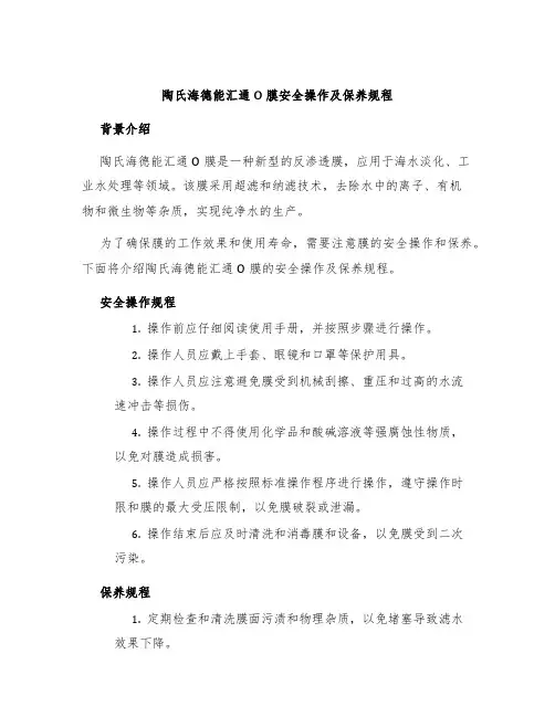
陶氏海德能汇通O膜安全操作及保养规程背景介绍陶氏海德能汇通O膜是一种新型的反渗透膜,应用于海水淡化、工业水处理等领域。
该膜采用超滤和纳滤技术,去除水中的离子、有机物和微生物等杂质,实现纯净水的生产。
为了确保膜的工作效果和使用寿命,需要注意膜的安全操作和保养。
下面将介绍陶氏海德能汇通O膜的安全操作及保养规程。
安全操作规程1.操作前应仔细阅读使用手册,并按照步骤进行操作。
2.操作人员应戴上手套、眼镜和口罩等保护用具。
3.操作人员应注意避免膜受到机械刮擦、重压和过高的水流速冲击等损伤。
4.操作过程中不得使用化学品和酸碱溶液等强腐蚀性物质,以免对膜造成损害。
5.操作人员应严格按照标准操作程序进行操作,遵守操作时限和膜的最大受压限制,以免膜破裂或泄漏。
6.操作结束后应及时清洗和消毒膜和设备,以免膜受到二次污染。
保养规程1.定期检查和清洗膜面污渍和物理杂质,以免堵塞导致滤水效果下降。
2.定期检测和维护膜的进水压力和流量、浓水压力和流量,并及时调整操作参数。
3.定期更换和清洗预处理设备,防止杂质和有机物堆积和沉积。
4.定期清洗和消毒膜和设备,定期更换滤芯和橡胶密封件等易损件。
5.保持膜和设备的干燥和通风,避免阳光直射和高温环境,以免膜老化和损伤。
总结陶氏海德能汇通O膜是一种高效、环保的水处理设备,是现代工业和城市生活中不可或缺的设备之一。
为了保证膜的正常运行和延长使用寿命,我们需要严格按照陶氏海德能汇通O膜的操作和保养规程进行操作和维护。
只有将安全操作和保养规程执行好,才能确保膜的工作效率和使用寿命,并为人类创造更美好的未来。
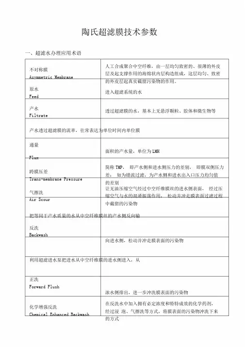
陶氏超滤膜技术参数一、超滤水办理应用术语不对称膜Asymmetric Membrane 人工合成聚合中空纤维,由一层均匀致密的、很薄的外皮层及起支撑作用的海绵状内层构造组成,这层均匀、致密的外皮层起真实截留污染物的作用。
原水Feed进入超滤系统的水产水Filtrate透过超滤膜的水,基本上无悬浮颗粒、胶体和微生物等产水透过超滤膜的流率,往常表达为单位时间内单位膜通量面积的产水量,单位为LMHFlux跨膜压差Trans-membrane Pressure 简称TMP,即产水侧和进水侧压力的差别,即膜双侧压力差;如为错流过滤,为产水侧和进水出入口压力均匀值的差别气擦洗Air Scour 让无油压缩空气经过中空纤维膜丝的进水侧表面,经过压缩空气与水的混淆振荡作用,松动并冲走膜表面过滤过程中截留的污染物把等同于产水质量的水从中空纤维膜丝的产水侧反向输反洗Backwash向进水侧,松动并冲走膜表面的污染物利用超滤进水泵把进水从中空纤维膜的进水侧进入,从正洗Forward Flush浓水侧排出,进一步冲洗膜表面的污染物化学增强反洗Chemical Enhanced Backwash 在反洗水中加入拥有必定浓度和特特成效的化学药剂,经过浸泡、气擦洗等方式,将膜表面的污染物冲洗下来的方式化学冲洗Cleaning In Place 简称CIP,即用配置好的酸、碱或杀菌剂化学药剂从进水侧进入中空纤维膜,从浓水侧和产水侧循环回流到冲洗水箱进行冲洗的方式,将膜表面的污染物有效去除回收率Recovery产水占原水的百分比将膜截留的物质从膜组件浓水口排放掉,防备被截留的浓水排放过滤Concentrate Bleed物质在膜进水侧发生累积错流过滤Cross Flow进水沿平行于膜面方向流动,有助于冲洗膜表面的污染物第1页/共11页二、陶氏DOW TM超滤膜产品一览表SFP‐2880超滤膜组件长度规格(80‐80英寸长,60‐60英寸长)超滤膜组件公称直径规格(8‐8英寸直径,6‐6英寸直径)陶氏超滤膜资料属性代号(2‐PVDF)陶氏超滤产品型号(SFP‐用于预办理,SFD‐用于饮用水)表2-1超滤膜组件的膜资料膜资料名称膜资料缩写代号聚砜PS1聚偏氟乙烯PVDF2聚醚砜PES3聚丙烯腈PAN4聚丙烯PP5聚乙烯PE6醋酸纤维素CA7芬芳聚酰胺APA8聚氯乙烯PVC9重生纤维素RC10表2-2超滤膜组件的用途说明产品型号用途划分SFP预办理SFD中水/污水回用SFR饮用水办理第2页/共11页表2‐3不一样超滤膜资料的接触角数据序号膜资料接触角01纤维素(CA)12~45°02聚醚砜(PES)44~81°03聚丙烯(PP)108°04聚砜(PS)38~81°05聚偏氟乙烯(PVDF)30~66°备注:值越小,表面资料越亲水,越亲水抗污染性能就越好。
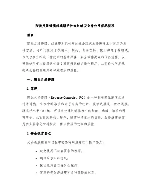
陶氏反渗透膜超滤膜活性炭过滤安全操作及保养规程前言
陶氏反渗透膜、超滤膜和活性炭过滤是现代水处理技术中常用的三
种方法,可广泛应用于饮用水、制药、食品饮料、化工和电子等领域。
本文旨在介绍这三种技术的基本原理、安全操作要点和保养规程,以
确保使用者在使用这些设备时遵循正确的操作程序,从而最大限度地
提高设备的使用寿命和处理水的质量。
一、陶氏反渗透膜
1. 原理
陶氏反渗透膜(Reverse Osmosis,RO)是一种利用高压迫使水通
过半透膜,将水中的溶质和离子分离的技术。
反渗透膜是一种半透膜,膜孔径小于100埃,可以有效地过滤掉水中的细菌、病毒、溶质和游
离离子,从而达到除盐、脱色、脱菌和净化水的目的。
反渗透膜通常
是由多层净化材料构成,保证传质的效率和质量。
2. 安全操作要点
反渗透膜在使用过程中需要特别注意以下操作要点:
•避免使用不符合要求的水源;
•确保给水水压稳定;
•保证压力容器密封性完好;
•定期检查反渗透膜和各种管路的状况;。
陶氏超滤膜2880技术参数1. 引言超滤膜是一种常用于分离和过滤液体的薄膜,其孔径较小,可以有效地去除溶质和悬浮物。
陶氏超滤膜2880是一种高效、高通量的超滤膜,本文将介绍其技术参数及特点。
2. 技术参数陶氏超滤膜2880具有以下主要技术参数:2.1 膜材料陶氏超滤膜2880采用聚酰胺材料制成,聚酰胺是一种具有良好耐化学性和机械性能的聚合物材料。
该材料在超滤过程中能够有效地分离溶质和悬浮物,并保持较高的通量。
2.2 孔径大小陶氏超滤膜2880的孔径大小为0.01微米(μm),这意味着只有小于等于0.01μm的颗粒才能穿过该膜。
这样可以有效地去除大部分溶质、病毒、细菌等微小颗粒,从而实现液体的分离和纯化。
2.3 通量陶氏超滤膜2880具有较高的通量,通量是指单位时间内通过膜面积的液体体积。
该膜的通量可达到5000升/平方米/小时(L/m²/h),这意味着在相同时间内可以处理更多的液体,提高生产效率。
2.4 耐温性能陶氏超滤膜2880具有良好的耐温性能,可在较宽的温度范围内使用。
其耐温范围为0℃至45℃,适用于大部分工业生产环境下的超滤过程。
2.5 PH范围陶氏超滤膜2880适用于广泛的PH范围。
其适用PH范围为1至13,可以在酸性、中性和碱性环境下进行超滤过程。
2.6 操作压力陶氏超滤膜2880的操作压力为最大10巴(bar),压力越高,通过膜的液体流速越快。
然而,在选择操作压力时需要注意不要超过该膜所能承受的最大压力,以免损坏膜材料。
3. 特点与应用陶氏超滤膜2880具有以下特点和应用:3.1 高效分离由于陶氏超滤膜2880的孔径较小,可以有效地去除溶质和悬浮物,从而实现高效的分离和纯化。
该膜广泛应用于水处理、食品与饮料生产、药品制造等领域,可用于去除杂质、浊度、微生物等。
3.2 高通量陶氏超滤膜2880具有较高的通量,可以在相同时间内处理更多的液体。
这使得该膜在大规模工业生产中具有重要意义,能够提高生产效率和节约成本。
超滤膜的工作原理和操作方法超滤膜的工作原理和操作方法一、工作原理过滤是使液体通过多孔过滤介质以分离其中所含的固体颗粒的一种操作。
过滤介质截阻颗粒而让液体通过,随着被分离的颗粒变小,要求介质的通道也要变小。
如果颗粒小到亚微细粒的程度,膜孔大小就要趋近于能阻止溶液中大分子的通过。
这种利用半透膜的微孔过滤以截留溶液中大溶质分子的操作称为超滤,而这样的半透膜称为超滤膜。
超滤的驱动力是压力,通常高达1.0MPa。
运用液压迫使溶液透过膜并按溶质分子大小、形状等差异,把大溶质分子阻留在膜的一侧,成为浓缩液; 而小分子的溶质则随溶剂透过膜到另一侧,成为透过液流出。
如果将所得浓缩液用水稀释,再进行超滤,可使料液中的低分子溶质进一步随透过液流出,而高分子物质逐步得到提纯,这样的过程称为全滤(如图8-4)。
超滤具有分离和提纯的作用。
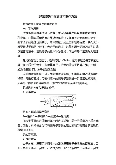
1. 分离作用图8-4 超滤原理示意图1—进料2—浓缩液3—清液4—超滤膜低分子质量的溶质随溶媒一起透过滤膜,高分子质量的溶质被截留,因此,料液被分为带有低分子溶质的透过液和带有高分子溶质及残留低分子溶质的浓缩液。
2. 提纯作用由于分离,提高了浓缩液中总固体里高分子量溶质的百分率,因此,提纯了高分子溶质。
在透过液中,低分子溶质由于从高分子溶质中分离出来,也得到了提纯。
二、超滤膜(一)超滤膜的膜渗机理料液在超滤膜内的流动问题比较复杂,简单的床层流动理论不能充分解释膜内的流动,它不是单纯属于一般毛细管内层流的机理。
通常膜渗机理有下述两种模型:1. 毛细流动模型在这种模型中,溶质的脱除主要靠流过微孔结构的过滤或筛滤作用,半透膜阻止了大分子的通过,按这一模型建立的流动是毛细孔中的层流流动。
2. 溶解扩散模型在这种模型中,假定扩散质的分子,先溶解于膜的结构材料中,而后再经载体的扩散而传递。
因为分子种类不同,溶解度和扩散度也就不同。
实际上,两种模型在膜渗传递中都可能存在,但反渗透以溶解扩散机理占优势,而超滤则以毛细流动机理占优势。
陶氏膜B30400安全操作及保养规程前言陶氏膜B30400是一种用于水处理的反渗透膜元件,具有高效过滤、高纯水产率等优点。
然而,在使用过程中需遵守一定的安全操作和保养规程,以保障设备的稳定性、延长设备使用寿命、保证产品水质等。
本文将为您详细介绍B30400反渗透膜安全操作及保养规程,帮助您更好地使用和维护您的设备。
安全操作规程1. 操作前在操作之前,需要进行以下检查:1.检查设备的用水质量,保证水质符合反渗透膜的使用要求。
2.检查水处理系统的各个部分是否连接正确,防止水漏等现象。
3.检查系统的压力情况,保证排出的水流量和质量符合双方协商的要求。
4.检查所需设备是否正常运行,并进行必要的维修和更换。
2. 操作过程中在使用过程中,应注意以下事项:1.需要降低水压之前,必须先关闭水源。
2.反渗透膜的使用温度范围为4℃-45℃。
不得在温度范围之外使用。
3.避免使用反渗透膜的中断时间过长,以免影响产品质量。
4.反渗透膜存储时,需放置于阴凉处(不超过35℃),并保持其湿润状态。
5.非专业人员不得随意拆卸系统。
3. 操作后在操作结束后,应进行以下操作:1.关闭水源及电源,清理水处理系统。
2.清洗反渗透膜滤芯,放置于阴凉处(不超过35℃)。
3.查看设备是否存在故障或漏水问题等,必要时请及时维修和更换。
保养规程1. 环境保养1.设备应放置在阴凉处,避免阳光直射和高温。
2.确保设备处于平稳状态,避免设备受到撞击和震动。
3.定期进行设备清洁,避免灰尘等杂物进入设备内部。
2. 滤芯保养1.定期更换反渗透膜滤芯,避免滤芯老化和污染对产品水质的影响。
2.根据滤芯清洗方法进行清洗,避免滤芯阻塞导致设备无法正常使用。
3. 操作规程1.操作人员需经过专业的操作培训,避免不当操作导致设备损坏和危险。
2.非专业人员不得随意拆卸设备,避免误操作导致安全事故。
3.定期进行设备维护,及时发现并解决问题,避免设备故障影响产品质量。
总结本文介绍了陶氏膜B30400反渗透膜的安全操作及保养规程,希望能为使用者提供帮助。
陶氏ro膜技术手册一、引言RO(Reverse Osmosis)逆渗透膜是一种重要的膜分离技术,广泛应用于水处理、海水淡化、废水处理等领域。
陶氏RO膜作为世界膜技术领域中的重要品牌,拥有卓越的膜分离性能和长久的使用寿命,一直受到行业的推崇和信赖。
本手册旨在详细介绍陶氏RO膜技术,为用户提供使用指南和技术支持。
二、RO膜技术原理RO膜是一种半透膜,通过对压力进行控制,使溶液中的溶质(水中的溶解物)逆向渗透,从而实现溶质与溶剂的分离。
RO膜的基本原理是利用膜的选择性透过性,使溶剂(通常是水)通过,而将溶质(溶液中的杂质、盐类等)截留在膜的一侧。
三、RO膜的应用领域1. 水处理:RO膜广泛应用于家庭自来水净化、饮用水处理、工业用水处理等方面。
其高效的过滤能力能够有效去除水中的有机物、重金属离子、微生物等,提供清洁、安全的饮用水。
2. 海水淡化:由于全球淡水资源的日益减少,海水淡化技术成为一种重要的解决方案。
陶氏RO膜在海水淡化领域具有优异的脱盐效果和稳定的性能,可广泛应用于海洋淡化厂、海水养殖等领域。
3. 废水处理:陶氏RO膜在工业废水处理中担当重要角色,能够有效去除废水中的溶解物、重金属离子等有害物质,提高废水的处理效果,减少对环境的影响。
四、RO膜产品介绍根据不同的应用领域和处理对象,陶氏RO膜提供多种产品系列。
常见的产品系列包括:1. 海水淡化系列:专门设计用于海水淡化厂,具有较高的脱盐率和稳定的性能。
2. 密闭系统系列:适用于家庭自来水净化、工业用水处理等领域,提供高效的过滤和去除杂质的功能。
3. 高温耐受系列:用于高温环境下的水处理,能够忍受高温条件下的工作。
4. 高砷富锌系列:专为含有大量砷和富锌的水处理而设计,具有出色的去除效果。
五、使用指南1. 准备工作:使用RO膜前,确保水源无明显污染,避免杂质对膜的损害。
另外,在膜组件安装前,确保设备清洁,以免影响膜的运行效果。
2. 操作要点:根据具体的需要和水质特点,选择合适的操作条件,包括进水压力、溶液浓度、温度等参数。
陶氏超滤产品技术手册作为一家全球领先的工程材料和科学研究公司,Dow公司致力于为客户提供各种高质量的工程材料以及创新的科技。
在这些产品中,陶氏超滤产品是其中之一。
陶氏超滤产品是一种用途广泛的膜技术,能够通过分离物质颗粒大小来过滤清洁水源或废水,有效地净化水质。
陶氏超滤技术已经在许多工业、商业和家庭环境中得到了广泛应用。
为了帮助客户更好地了解陶氏超滤技术,Dow公司发布了陶氏超滤产品技术手册。
该手册详细介绍了陶氏超滤膜的构成和产生原理,以及超滤膜的物理性质和处理效果。
此外,手册还介绍了如何根据不同的水源和用途选择适当的超滤膜,并且为客户提供了使用陶氏超滤膜的有效方案。
手册包含以下内容:第一部分:超滤膜的概述手册的第一部分提供了陶氏超滤膜的概述。
超滤膜是由几种不同材料组成的多层复合膜,这些材料通常是聚酰胺(PA)及聚碳酸酯(PC)。
超滤膜能够过滤出直径可达0.1微米的颗粒,能够有效地过滤水中的细菌、病毒、有机物和一些重金属等污染物。
第二部分:超滤膜的物理性质手册的第二部分介绍超滤膜的物理和化学性质。
超滤膜具有一定的孔径大小,因此,它能够过滤物质的颗粒大小是有限制的。
此外,超滤膜还有很好的抗氧化和耐腐蚀性能,能够适应各种复杂的水质环境。
第三部分:超滤膜的应用手册的第三部分介绍了超滤膜的应用,包括工业和商业的应用。
超滤膜广泛应用于制药、电子、化工、食品和饮料生产、废水处理、海水淡化和饮用水净化等领域。
此外,超滤膜还可以应用于家庭饮用水净化器中,提供家用净水服务。
第四部分:根据不同水源选择超滤膜手册的第四部分介绍了如何根据不同的水源选择超滤膜。
手册提供了一些关于选择超滤膜的建议和技巧,这些建议和技巧能够帮助客户选择出适合自己需要的超滤膜。
选择适当的超滤膜不仅可以提高处理水的效率,还能够有效地减少能耗和成本。
第五部分:使用超滤膜的有效方案手册的第五部分介绍了使用超滤膜的有效方案,例如在废水处理中的应用。
该部分还提供了超滤膜的周期维护技巧和操作方法。
陶氏陶瓷超滤膜简介2019.10.29陶氏超滤膜可去除溶液中的大分子、胶体、蛋白质、微粒等,具有使用压力低、产水量大、便于操作的特点。
通过测试中空纤维超滤膜装置深度净化制酒原水的处理效果,证明超滤膜净水装置能有效地消除水在管网中的二次污染,进一步提高水质。
陶氏超滤膜工作原理是在常温下以一定的压力和流量,利用不对称微孔结构和半透膜介质,以膜两侧的压差为动力的一种新型膜分离技术。
超滤膜特有的0.01—0.1um孔径可有效阻留细菌,大多数病毒,胶体以及淤泥。
从而达到分离、分级、纯化、浓缩目的。
超滤膜特征1、超滤膜具有超小的孔径,能够高效的去除颗粒物,细菌,大部分病毒和胶体,并结合着均匀的膜空和外压式结构,可以确保组件在多种复杂的水质条件下,仍然可以保证高效稳定的运行。
当压力增大时,可以通过反冲洗和气洗的方式进行清洗和维护,延长膜的寿命。
2、超滤膜的孔径超小,确保高效过滤,水质达到用水标准。
除菌率可达到99.99%。
3、陶氏超滤膜材质超强,可以延长使用寿命。
独特的双层结构膜丝,抗化学性较强,足以抵抗强酸强碱的侵蚀,机械的强度高,不易断裂。
4、陶氏陶瓷超滤膜结构抗压力强,能够保证持续低能耗稳定运行。
其外压结构,过滤面积更大,进水要求低,适合的原水范围更广阔。
外压的膜丝不易堵塞,清洗频率大幅降低、节约能耗,节省成本。
陶瓷超滤膜应用领域1、陶瓷超滤膜作用:陶氏陶瓷超滤膜SFP 2660对细菌和大多数病毒的去除率可达到99.9%。
过滤精度高,保证饮水安全。
2、RO预处理:超滤具有高效的固体分离和去除截留病原体等特点,还能够适应海水复杂的变化,因此被广泛应用于海水淡化(RO)预处理,为RO系统提供高质量的产水,保证系统的稳定运行。
3、废水回用:陶氏陶瓷超滤膜低能耗,高分离效率的特点,既能对废水进行有效的净化,又能回用其中的有用物质,同时还可节省能源。
使超滤成为废水回用和废水资源化的主要应用技术。
陶氏陶瓷超滤膜利用超小孔径的双皮层结构H—PVDF膜,高效去除颗粒物,细菌,大部分病毒和胶体。
陶氏纳滤膜安全操作及保养规程基本概念什么是陶氏纳滤膜?陶氏纳滤膜是一种分离膜,利用在高压下通过陶氏纳滤膜,可以将水中的无机离子、有机物质、细菌等微小颗粒和溶解物分离出来,从而实现水的过滤。
为什么需要操作规程?陶氏纳滤膜在使用过程中需要注意安全,同时也需要进行保养和维护。
而操作规程的制定可以帮助人员正确使用、保养和维护陶氏纳滤膜,保障生产和使用的顺利进行。
安全操作规程操作程序1.在操作之前,应对陶氏纳滤膜进行检查,并确保设备正常。
2.保持操作区清洁,严禁杂物和碎片进入操作区。
3.操作过程中应佩戴适当的防护装备,如手套、护目镜等。
4.操作过程中应遵守设备使用规范,严格禁止违规操作。
5.操作结束后,应对设备进行清洗和消毒。
安全措施1.维护机器运行的稳定和安全性,确保设备正常运行。
2.在处理具有腐蚀性和毒性物质的前提下,必须佩戴适当的防护装备。
3.定期检查陶氏纳滤膜的使用情况,并及时更换。
4.在发现陶氏纳滤膜损坏或出现端部掉落现象时,应立即停止使用。
5.严格按照陶氏纳滤膜操作规程进行操作,严禁违规操作。
保养规程保养程序1.在使用过程中,应随时注意设备的清洁。
2.定期对陶氏纳滤膜进行检查和保养。
3.定期对设备进行维护和保养。
4.定期更换陶氏纳滤膜。
保养措施1.定期清洗陶氏纳滤膜并进行消毒。
2.避免在高温或低温环境下存放陶氏纳滤膜,以免影响产品质量。
3.定期检查陶氏纳滤膜的密封性和性能。
4.关注工厂和设备的清洁和消毒状况,及时修复损坏的设备。
5.定期更换陶氏纳滤膜,避免使用过期或已损坏的陶氏纳滤膜。
结论陶氏纳滤膜是一种功能强大的分离膜,使用陶氏纳滤膜可以将水中的无机离子、有机物质、细菌等微小颗粒和溶解物分离出来,从而实现水的过滤。
在使用过程中,应注意安全,严格遵守操作规程;在维护和保养方面,应定期检查和更换陶氏纳滤膜,避免使用过期或已损坏的陶氏纳滤膜。
只有正确地使用和保养陶氏纳滤膜,才能保障生产和使用的顺利进行。
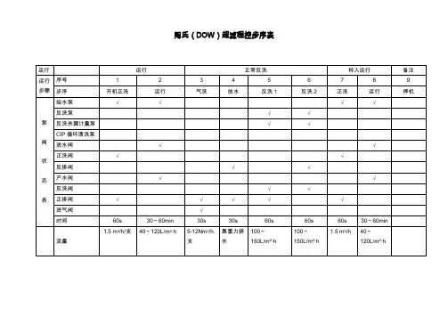
DOW TM超滤膜的运行与操作一、过滤超滤膜系统在启动时,建议进行2-3 分钟的正洗来除去膜组件里残留的化学品及空气。
正洗是进水从膜组件下部进水口进入膜组件,冲洗膜丝外表面,从膜组件顶部浓水口排出,这一步骤时间内将不过滤进水。
在正洗完成后,系统可以转换到过滤运行状态。
通常一个运行周期为20-60 分钟,根据进水条件和清洗程序而变化。
在正常的过滤状态下,100%的进水被过滤即全流过滤。
由于在过滤过程中截留污染物,跨膜压差(TMP)将会上升,在预先设定的运行步骤的结尾,会转入到气擦洗和反洗的清洗步骤。
二、气擦洗超滤膜系统按照自动控制程序将转入气擦洗步骤,气擦洗是利用压缩空气产生的气泡松动膜丝外表面截留的污染物。
压缩空气从膜组件底部进气口进入到膜丝外表面,从顶部浓水口排出。
三、底部排水在气擦洗步骤后,停止进气,打开下排放阀,将膜组件重力排干,随排水带走松动的污染物。
排水完毕之后进行第一步反洗,即上反洗步骤。
反洗水从膜组件上部产水口进入膜丝内部,从与运行产水相反的方向透过膜丝,反洗废水在膜丝外部汇集,打开反洗上排放阀,使反洗废水从膜组件顶部浓水口排出。
上反洗步骤能首先清洗膜组件污染最严重的上端区域。
第二步反洗,即下反洗步骤,去除膜组件下端区域的污染物。
保持反洗水从膜组件上部产水口进入,打开反洗下排放阀,使反洗废水从膜组件下部进水口排出,可有效去除下端的污染物。
六、正洗在反洗结束后,需进行正洗以去除任何残留的污染物和/或化学药品,并排除聚集在膜组件内部的空气。
完成正洗后,超滤系统即可重新投入到过滤运行状态或者备用状态。
七、化学加强反洗(CEB)在通过常规气擦洗辅助反洗步骤无法除去所有污染物的情况下,通过在反洗时加入化学药剂可以加强反洗的效果,即化学加强反洗(CEB, C hemical E nhanced B ackwash)。
CEB 过程包括一个气擦洗过程、加入化学药剂反洗、浸泡和将污染物和化学药剂冲出的常规气擦洗辅助反洗过程。
在CEB 过程中,非常重要的一点是在加入化学药剂的反洗前,要保证将绝大部分的污染物通过常规反洗从膜组件中除去。
这样,化学药剂才可以直接作用到那些难以除去的污染物上。
同样重要的是要保证整个膜组件中充满合适浓度的化学药剂和合理的浸泡时间。
通常浸泡可持续 5 至10 分钟,有时为了使化学药剂与黏附在膜丝表面或进入膜丝孔通道内的污染物充分接触,也可延长浸泡时间。
浸泡后,要保证将所有的化学药剂冲洗出整个系统。
CEB 所使用的化学药剂种类根据原水水质可能产生的污染物进行选择,CEB 频率根据产生的污染物频繁情况而定。
一般使用的化学药剂为NaOCl、NaOH 和HCl 等。
根据所使用的化学药剂的不同,CEB 一般分为针对由于原水中有机物及生物引起的污染的碱CEB,和针对由于原水中铁、铝的胶体或者硬度结垢引起的无机物污染的酸CEB:(目标 pH 12)碱CEB:0.1% NaOCl + 0.05% NaOH酸CEB:0.1% HCl 或H2SO4 (目标 pH 2)1、DOW TM超滤的化学加强反洗(CEB)上反洗2、DOW TM超滤的化学加强反洗(CEB)下反洗八、就地化学清洗(CIP)就地化学清洗(CIP)操作包括反洗和化学品循环清洗。
CIP 是一个基于需求的操作。
CIP 频率受到给水水质的影响,频率可以从 1 个月到 3 个月不等。
CIP 前要执行一次的常规反洗,其步骤包括气擦洗、底部排放、上反洗和下反洗。
反洗的步骤通常重复 3 到8 次,以去除各种不需要的化学清洗即可去除的污染物。
反洗步骤完成后,通过重力排水排掉膜组件中多余的水,防止后续CIP 化学药品浓度被稀释。
CIP 清洗液在膜组件和化学清洗水箱之间循环30 分钟(CIP 药品从膜组件进水侧打入)。
一部分CIP 清洗液的滤液也被收集并循环回的化学清洗水箱。
请注意,CIP 清洗液可以加热到40oC,以提高去除膜组件中污染物的效率。
循环清洗后可以浸泡60 分钟或更长的时间,浸泡时间长短主要取决于膜组件的污染程度。
浸泡步骤后,再次将CIP 清洗液循环30 分钟。
循环清洗完成后再执行一次气擦洗和排水,以排放掉膜组件中CIP 清洗液。
随后执行 2 步反洗(上反洗和下反洗)和正洗,以去除膜丝外部任何剩余的污染物。
注意:经过CIP 后,转入正常的操作运行步骤时,UF 膜丝产水侧残留有CIP 化学品(特别是氧化剂),如后续工艺为反渗透,应该将CIP 后第一次正常运行产水排放,以避免反渗透膜的氧化。
上面描述的CIP 步骤为一个单一的碱或酸的CIP 清洗过程。
如果酸和碱清洗都需要,CIP 的步骤是将碱CIP 过程和酸CIP 过程各执行一遍。
附录.化学清洗方法与步骤1 序言超滤系统可能受到进水中存在各种杂质的污染,比如悬浮物、胶体、有机物、微生物和水合金属氧化物等。
污染(fouling)就是指覆盖在膜表面上和吸附在膜孔道里的各种沉积物,包括水中的结垢物。
预处理的目的在于尽量减少导致膜污染的杂质物质,通过安装合适的预处理设备,如前置过滤器、混凝/澄清或者过滤设备,选择恰当的操作条件,就能达到这一目标。
超滤膜污染通常被认为是以下一种或者几种污染的组合:?无机物污染/结垢?微粒/胶体污染?微生物/生物污染?有机物污染引起以上这些污染可能有以下因素:?预处理系统不完善?预处理运行不正常?进水组份或其它条件改变?操作控制不当?膜面长时间累积沉淀物?季节性的藻类繁殖污染?化学加药系统失灵?反洗和学学加强反洗不当?系统停机程序和保存措施不当?系统选材不合适(泵和管道等)膜发生污染会导致系统性能的下降,如产水量和通量衰减、跨膜压差增高以及较高的化学药剂耗量和能耗。
由于陶氏DOW?超滤膜采用具有极佳的物理性质和化学耐受性的亲水改性聚偏氟乙烯(H-PVDF)膜丝材料和独特膜组件结构设计,能够承受较高的氧化剂,pH 和温度条件,只要措施得当,就可以很有效地进行化学清洗,最大限度地恢复超滤系统的性能。
清洗液浓度,清洗时间,温度和气擦洗频率都会影响清洗效果。
但若拖延太久才进行清洗,可能会导致不可逆的结果并导致膜组件或附属设备潜在的物理性损坏,即清洗无法恢复膜的性能。
重度污染的膜会变得很难清洗因为药剂很难渗到膜表面并冲走污染物,因此,如果出现膜污染的情况,清洗频率应适当加强。
化学清洗是解决膜污染问题最有效的方法,针对特定的污染,只有采取相应的清洗方法,才能达到好的效果,若错误地选择清洗化学药品和方法,有时会使情况恶化。
因此,在清洗之前需先确定膜表面的污垢物种类,通常有以下几种分析方法来确定:?分析系统性能数据,请参阅故障排除一节的详细介绍?分析进水组成,发生污染物的可能性或许经过分析原水水质报告,就能显而易见的发现?检查以往的的清洗记录和效果?分析进水测定SDI 值的滤纸上所截留的物质?检查超滤气擦洗和反洗排放的废水中污染物?检查膜组件的进水端的污染物,如为红棕色,则表示可能已发生铁的污染;泥状或胶状沉积物通常为微生物或有机物污染。
2 化学清洗条件超滤系统常规运行过程中,超滤膜丝表面可能会被悬浮物颗粒、胶体颗粒、微生物或不溶性的有机物污染,持续积聚到不能通过常规的反洗或化学加强反洗来恢复,导致标准化的产水量下降和跨膜压差升高。
当下列情况出现时,需要清洗膜组件,以恢复系统性能:?标准化产水量下降25%?标准化跨膜压差上升 1.0bar?运行跨膜压差上升到最大值 2.1bar?如果您没有标准化您的运行数据,请参考以上这些数据来决定是否是否进行化学清洗日常操作时必须严格监控超滤系统的运行性能,包含运行压差和产水流量,随着超滤膜的污染,压差将增高,产水流量下降。
需要注意的是,如果进水温度下降,超滤膜产水流量也会下降,这是正常现象并非膜污染所致,此时超滤膜可能并不需要清洗。
陶氏化学公司开发了一个超滤膜标准化软件工具,用户可以借助此工具来分析系统运行性能,区分正常现象和由于污染造成的性能衰减并决定何时应该进行化学清洗。
陶氏超滤膜标准化工具可以咨询您当地的陶氏水处理及过程解决方案业务部的技术服务人员提供。
3 化学清洗安全注意事项1. 在下列各章节中,当使用任何清洗化学品时,必须遵循获得认可的安全操作规程。
关于化学品安全性、使用方法和排放处置方面的细节请咨询该化学品制造商。
2. 当准备清洗液时,应确保在进入膜组件之前,所有的清洗化学品得到很好的溶解和混合。
3. 在清洗液循环期间,确认最大的温度和pH 值限制,参考下表1。
表 1. 化学清洗pH 和温度限制4 化学清洗设备化学清洗所需设备参见下面的化学清洗系统流程图,针对DOWTM 膜组件的清洗液pH 值范围可能在2~12 之间,因此化学清洗系统设备应采用耐腐蚀材料建造。
清洗种类pH,Max/Min 温度,Max碱性清洗12,Max. 35°C(95°F)酸性清洗2,Min. 40°C(104°F)图1. 化学清洗系统流程图图中:CIP Tank 化学清洗水箱 PE, PP or FRPCIP Pump 低压泵 316SS, or 非金属复合材料CIP Cartridge Filter 化学清洗过滤器 PP,5 或10 微米, PVC, FRP, or SS 外壳HT 化学清洗水箱加热器(可选)TIT 温度传感器LIT 液位传感器LG 液位计PG 压力表FIT 流量传感器AIT pH 分析仪1. 化学清洗水箱作混合与循环用,材料可以是聚乙烯(PE)、聚丙烯(PP),或玻璃钢(FRP)。
清洗水箱应设有可移动的盖子以及温度计,提高清洗温度有利于提高清洗效率,建议清洗过程中应按表9-1 规定的清洗液pH 值和温度限制。
由于低温下清洗化学动力学极低,建议清洗液温度不应低于15oC(59oF),此外,在某些地区,清洗系统中则需要安装冷却部件,因此设计清洗系统时应考虑加热和冷却要求。
确定化学清洗水箱大小的大致方法是膜组件的容积与清洗液循环管道的容积之和。
例如清洗10 支陶氏SFP-2880 膜组件的系统时,下列计算可以做为参考:膜组件的容积Vm =39 L(10.3gal) / SFP-2880V10 =39x10 = 390 L = 0.39m3 (103gal)管道的容积,假设循环管道10m (32.8ft)长,DN50 PN10 (2.5inch SCH80) U PVC 管道Vp =r2L=3.14x(0.025m)2x(10m)=0.020m3 (5.2gal)化学清洗水箱的容积Vct = V10+ Vp =0.39+0.02 =0.41m3 (108.2gal)因此,所需配制的清洗液体积约为0.41m3,由于清洗水箱完全装满可能产生溢流,一般应考虑20%的富裕度,本例应选择体积为0.50m3 的耐腐蚀水箱作清洗水箱。