胶带产品说明书A样本
- 格式:doc
- 大小:174.00 KB
- 文档页数:11
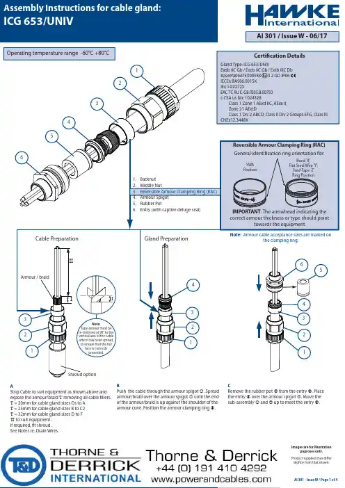
Note:Tape armour must bere-trimmed at 90° to thevertical axis of the cableafter it has been spread,to ensure that the fullface is correctlypresented.IArmour / braidIIIShroud option621354564214321 3213Braid 'X',Flat Steel Wire 'Y',Steel Tape 'Z'Ring PositionSWAPositionGeneral identification ring orientation for:Reversible Armour Clamping Ring (RAC)Gland Type: ICG 653/UNIVExdb IIC Gb / Exeb IIC Gb / Extb IIIC DbBaseefa06ATEX0058X II 2 GD IP66IECEx BAS06.0015XIEx 14.0272XEAC ТC RU C-GB.ГБ05.B.00750c CSA us No: 1024328Class 1 Zone 1 AExd IIC, AExe II,Zone 21 AExtDClass 1 Div 2 ABCD, Class II Div 2 Groups EFG, Class IIICNEx12.3448XCertification DetailsOperating temperature range -60°C +80°CNote: Armour cable acceptance sizes are marked onthe clamping ring.IMPORTANT: The arrowhead indicating thecorrect armour thickness or type should pointtowards the equipment1. Backnut2. Middle Nut3. Reversible Armour Clamping Ring (RAC)4. Armour Spigot5. Rubber Pot6. Entry (with captive deluge seal)Cable Preparation Gland PreparationAStrip Cable to suit equipment as shown above andexpose the armour/braid 'I' removing all cable fillers.'I' = 20mm for cable gland sizes Os to A'I' = 25mm for cable gland sizes B to C2'I' = 32mm for cable gland sizes D to F'II' to suit equipment.If required, fit shroud.See Notes re. Drain Wires.BPush the cable through the armour spigot ④. Spreadarmour/braid over the armour spigot ④ until the endof the armour/braid is up against the shoulder of thearmour cone. Position the armour clamping ring ③.CRemove the rubber pot ⑤ from the entry ⑥. Placethe entry ⑥ over the armour spigot ④. Move thesub-assembly ① and ② up to meet the entry ⑥.AI 301 - Issue W / Page 1 of 4AI 301 / Issue W - 06/17 Assembly Instructions for cable gland:ICG 653/UNIVProduct supplied may differslightly from that shown.Images are for illustrationpuproses only.CompoundTape35mmRemove surplus compoundRemove surplus compoundCompound5465621242663142AI 301 - Issue W / Page 2 of 4When handling this material, the gloves supplied must be worn. The epoxy compound is supplied in the form of a two part package. These should be mixed into the ratio of 1:1 until both colours have blended into one, without any streaks. Rolling and folding is the most satisfactory method of obtaining an even blend. Once mixed, the compound must be used within 30 minutes. After this time it will begin to stiffen. The compound should be kept at an ambient temperature of no less than 20°C prior to using. At lower temperatures it becomes difficult to mix. Should any compound come into contact with the skin it should be cleaned off with skin cleaner and not allowed to dry on the skin. Only compound for immediate terminations should be mixed.The mixing and installation of the compound at an ambient temperature below 4°C is not recommended due to extended curing periods.The storage of the compound shall be at temperatures between 5°C and 30°C.DHold the entry ⑥ in position with a spanner/wrench to prevent rotation. Hand tighten the middle nut ② onto the entry ⑥ and turn a further half to three quarters of a turn with a spanner/wrench.EUnscrew the middle nut ② and visually inspect that the armour/braid has been successfully clamped between the armour spigot ④ and the armourclamping ring ③. If armour/braid not clamped repeat assembly.FRemove the entry ⑥, spread the cable cores out for the compound packing. Pack the compound between the cores shown. See notes below and Fig. 7 for compound preparation.GWith all gaps and voids filled, bring the conductorsback together and pack more compound around the outside of the conductors. Tape the conductors together to prevent disturbance of the compound seal. Pass the rubber pot ⑤ over the armour spigot ④ and remove any surplus compound. from the top of rubber pot ⑤ and the joint face as indicated.H Replace the entry ⑥ over the rubber pot ⑤ ensuring that compound does not cover the end of ⑤.ILocate and hand tighten the sub-assembly ① and ② to the entry ⑥.IMPORTANT: The conductors must not be moved for a minimum of four hours.EPOXY COMPOUND PREPARATION1.0 INSULATING DRAIN WIRES WITH HEAT SHRINK OR COLD SHRINK TUBING 1.1 Fold back the armour / braid and bend it to right angles from the inner sheath. 1.2 Remove foils and tape level with the outer sheath, exposing the drain wires and insulated conductors. Cut back a further 10mm of inner sheath.1.3 Pass 100mm length of heat shrink or cold shrink tubing over the drain wire until it comes into contact with the foils, then shrink the tubing evenly down onto the drain wireso that no air pockets occur.1.4 To insulate the joint between the foils and the tubing a suitable piece of 10mm long shrink tubing or neoprene stretch tubing or a 10mm wide lap of PVC tape may be used. 1.5 After completing 1.1 to 1.4 on each drain wire, lay the armour / braid parallel to the cable, if applicable, then carry out instruction B.DRAIN WIRE PREPARATIONThe following instructions are the various BASEEFA approved methods of passing drain wires etc. through the compound barrier and should be followed if permitted by cable installation specifications.2.0 INSULATING DRAIN WIRES / SCREENS WITH SEPARATE INSULATED CRIMPED CONDUCTORS OR SOLDERED CONNECTION 2.1 Fold back the armour / braid and bend to right angles from the inner sheath. 2.2 Remove a further 15mm of inner sheath (See Fig. 1). 2.3 Unravel one or two groups of wires from the screen wires, then remove the remainder of the screen wires (See Fig. 2). 2.4 Twist the group of screen wires into a pigtail and cut to 15mm long. 2.5 Crimp an insulated conductor to the pigtail wih a suitable insulated butt ferrule (or soldered connection), leaving enough length of the insulated conductor to enable theremote end to be connected to the earth terminal in the equipment. (See Fig. 3). Note: There shall be a minimum of 10mm of compound on both ends of the crimped /soldered joint.2.6 To insulate the joint between the screen wires and the insulated conductor, place one lap of PVC insulating tape over the exposed metallic joint. 2.7 After completing 2.1 to 2.6 on each drain wire, lay the armour / braid parallel to the cable. Then carry out instruction B.3.0 INSULATING DRAIN WIRES WITH INSULATING VARNISH OR PAINT 3.1 Fold back the armour / braid and bend it at right angles from the inner sheath. 3.2 Remove the foil and tape level with the inner sheath exposing the drain wires and conductor pairs. 3.3 Cut back a further 10mm of inner sheath (See Fig. 4). 3.4 Spray or paint the drain wires with insulating varnish or paint, then leave to dry (See Fig. 5) 3.5 To insulate the foil ends a suitable piece of 10mm long shrink tubing or neoprene stretch tubing or a 10mm wide lap of PVC tape may be used (See Fig. 6).3.6 After completing 3.1 to 3.5 on each drain wire, lay the armour / braid parallel to the cable. Then carry out instruction B.Outer SheathArmour / braidArmour / braid15mm10mmInner Sheath One or two groupsof screen wiresInsulated ConductorCrimp or SolderScreen WiresInner Sheath FoilsDrain WireInsulatedDrain WireSleevingFig. 1Fig. 2Fig. 3Fig. 6Fig. 5Fig. 41652612AI 301 - Issue W / Page 3 of 4JAllow the compound to cure. (See Fig. 7 for Curing Times). Untighten the sub-assembly ① and ② from the entry ⑥ to enable inspection.The rubber pot ⑤ may be removed for inspection to ensure that the packing is satisfactory.Add further compound if necessaryKRe-assemble the rubber pot ⑤ and the entry ⑥. Tighten the sub-assembly ① and ② to the entry ⑥ until resistance is felt and add half to three quarters of a turn to ② with a spanner / wrench. Tighten the backnut ① to form a seal around the cable, then tighten a further full turn using a wrench / spanner. Ensure that the middle nut ② does not rotate when tightening the backnut. Ensure that the deluge seal is pulled down into position. Locate the shroud over the cable gland, if applicable.1289080706050403020100S h o r e H a r d n e s sTime (Hours)40 ºC 25 ºC 4 ºC416Epoxy CompoundCure Time Vs. TemperatureFig. 7CABLE GLAND SELECTION TABLEEntry ThreadSize MetricSize RefNPTAcross Flats C o m p r e s s e d L e n g t hAcross CornersHexagon Dimensions O A B C C2D E FM20M20M25M32M40M50M63M75½" - ¾"2" - 2½"2½" - 3"11.016.221.926.337.147.859.012.518.424.729.741.753.566.2/65.326.532.539.550.560.670.888.0104.0Inner Sheath/CoresOuter Sheath Cable Acceptance Details8.910.0Min.Max.9.512.516.922.028.036.046.057.016.020.526.033.041.052.665.378.00.8/1.250.8/1.251.25/1.61.6/2.01.6/2.01.8/2.51.8/2.51.8/2.50/0.8Os M20½"½"26.567.067.073.678.082.488.792.799.467.0M a x i m u m L e n g t h83.084.091.098.0100.0116.0124.0122.083.08.910.0 5.512.00.8/1.250/0.80/0.8 0/0.70/0.70/0.70/1.00/1.00/1.0¾" - 1"1" - 1¼"1¼" - 1½"1½" - 2"12153042608010012012ATEX Max. No. of Cores Max.Over Cores Max. Inner Sheath Steel Wire Armour/Tape/BraidOrientation2Orientation 124.030.036.046.055.065.080.095.024.0ACCESSORIES:Before cable gland assembly or stripping of the cable gland assembly, consideration should be given to any cable gland accessories that may be required, such as: -● Shroud, to offer additional corrosion protection.● Locknut, to secure cable glands into position.● Sealing washer, to offer additional ingress protection of the enclosure at thecable gland entry.● Earthtag, to provide an external armour / braid bonding point.● Serrated washer, to dampen any vibrations that may loosen the locknut orcable gland assembly.SCHEDULE OF LIMITATIONS - Baseefa ATEX / IECEx:1. These glands are suitable for use within an operating temperature range of-60°C to +80°C.2. When the gland is used for increased safety, the entry thread shall besuitably sealed to maintain the ingress protection rating of the associated enclosure.AI 301 - Issue W / Page 4 of 4EU Declaration of Conformity in accordance with European Directive 2014/34/EU Manufacturer: Hawke InternationalAddress: Oxford Street West, Ashton-under-Lyne, OL7 0NA, United Kingdom.Equipment: Group II Barrier Cable Glands Type: ICG 653/UNIVProvisions of the Directive fulfilled by the Equipment:Group II Category 2GD Exeb IIC Gb, Exdb IIC Gb, Extb IIIC Db – IP66Notified Body for EU-Type Examination: SGS-Baseefa 1180 Buxton UK EU-type Examination Certificate: Baseefa06ATEX0058X Notified Body for production: SGS-Baseefa 1180 Buxton UK Harmonised Standards used:EN 60079-0:2012+A11:2013, EN60079-1:2014, EN60079-7:2015, EN60079-31:2014.On behalf of the above named company, I declare that, on the date the equipmentaccompanied by this declaration is placed on the market, the equipment conforms with all technical and regulatory requirements of the above listed directives.………………………………….A. Tindall Technical Manager………………………………………Ti d ll● The compound may be adversely affected by some solvent vapours. If such vapours are likely to be present in the vicinity of the cable gland in service, suitable precautions may be necessary. (Contact Hawke's Technical Dept).● The compound cures at a Shore D hardness of 85, when it can be handled. The compound when fully cured is suitable for use at a temperature range of -60°C to +80°C.NOTES - c CSA us:1. Class 1 Division 2 suitable for Marine Shipboardapplications only according to CSA Standard 245 andIEEE45 / IEC 600092-353 Standards, or certified equivalent, for use on Shipboards and Offshore Rigs / Platforms only.2. Glands must comply with the Canadian Electrical Codeand National Electric Code requirements for threaded entries.3. For Exe applications, a sealing washer or thread sealantmay be required between the enclosure and the gland to maintain the IP rating of the enclosure.4. Drain wires and earth screening may pass through thecompound barrier using one of the methods which are details in this assembly instruction; heat shrink or cold shrink tubing, or addition of an insulated crimped or soldered conductor or insulation by varnish or paint.5. This cable gland may only be installed when temperatureis above +4°C. After completion of the installation, the assembly is then suitable for -60°C to +80°C.。
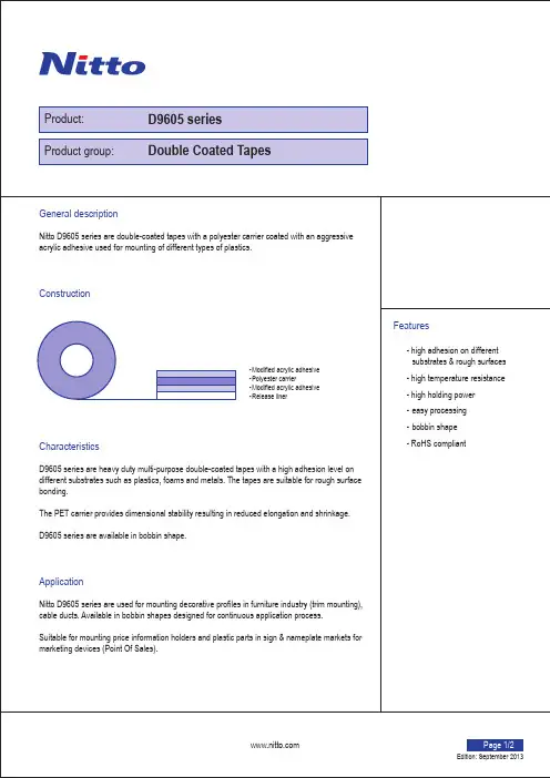
Page 1/2 Product:Product group:General descriptionNitto D9605 series are double-coated tapes with a polyester carrier coated with an aggressive acrylic adhesive used for mounting of different types of plastics.ConstructionCharacteristicsD9605 series are heavy duty multi-purpose double-coated tapes with a high adhesion level on different substrates such as plastics, foams and metals. The tapes are suitable for rough surface bonding.The PET carrier provides dimensional stability resulting in reduced elongation and shrinkage.D9605 series are available in bobbin shape.ApplicationNitto D9605 series are used for mounting decorative profiles in furniture industry (trim mounting), cable ducts. Available in bobbin shapes designed for continuous application process.Suitable for mounting price information holders and plastic parts in sign & nameplate markets for marketing devices (Point Of Sales).Features- high adhesion on different substrates & rough surfaces - high temperature resistance - high holding power - easy processing - bobbin shape - RoHS compliant- Modified acrylic adhesive - Polyester carrier- Modified acrylic adhesive - Release linerEdition: September 2013D9605 series Double Coated TapesGeneral conditions of use and precautions: The properties of the product might be adversely affected by various elements such as composition, condition and surface of and impurities in or on the substrate, temperature and humidity during storage and the surrounding environment at and after application and time of exterior use.When the product is used in combination with another material or process, the user shall assure the compatibility of the product in such combination and whether this combination results in the expected performance. The same principle applies in the event of product use in extreme conditions or circumstances, whether at or after the moment of application, including extended exposure to sunlight or extreme temperatures and pressure. Packaging, transport and storage:During transport and storage the product should always be protected against direct sunlightand extremes in temperature and humidity and contained in its original packaging. Once removed from its packaging, it should be promptly applied and remain shielded from direct sunlight and extreme temperature as well as protected against dust and other impurities.Liability:Except for its wilful misconduct, Nitto Europe’s liability shall be limited to a replacement, a reimbursement or an additional delivery of the product, and shall not exceed the purchase price of the products. In no event shall Nitto be liable in respect of any indirect or consequential damages, including loss of profits.The above limitations of liability shall equally apply if Nitto Europe has assisted in any manner with the selection, treatment or application of the product. Product information:This datasheet provides a general description of the product properties and application scope. Full technical details in connection with this product are presented in the customer product specification, which is available upon request.Please be advised that the information reflected in this datasheet is subject to change and the product described herein may be modified or discontinued without notice.For your local Nitto Europe sales office, please visit our web site: Copyright © 2013 NITTO EUROPE NV. All rights reserved.Nitto Europe NV has obtained following certificates:- ISO 9001- ISO 14001- ISO/TS 16949Please check our website for applicable scopeIf you require additional information on technical properties and application as well as product sampling or testing, please contact your local Nitto Europe sales office.Edition: September 2013Code: DS/01.11/E4 D9605 series ENG This datasheet replaces all previous versionsTechnical PropertiesGeneral physical propertiesTypical Value Test MethodAdhesive type Modified acrylic adhesiveTape thickness* 0.220 mm EN 1942Release liner D9605: Siliconised havana paper (90 g/m²)D9605S: Siliconised white PE coated paper (125 g/m²)Carrier type Polyester (0.050 mm)Adhesion to BA steel 2000 cN/20mm EN 1939Release value 30 cN/50mm Nitto Europe Test MethodStatic shear 1 mm/3h EN 1943Transport and storage conditions Temperature 15 to 30°CRelative humidity 40 to 75% RH* Tape thickness = Total thickness without linerDetails from the test methods are described on the customer product specification.Performance propertiesAdhesion in cN/20mm EN 1939PMMA PC ABS PP Glass2000 2300 1800 700 2300Weight Added Peel Off (WAPO) 2 h at 60°C, width 20mm, 100gPP 16 mm/2h ABS 13 mm/2h BA 3 mm/2hDynamic Shear 350 N/4cm² Tested after 15 min., 300mm/min.Saft test (Shear Adhesion Failure Temperature) 185 °C +0,5°C/min., 15x15mm, 200gWarrantyThe product is guaranteed to be free from defect in material and workmanship at the time ofdelivery and will be suitable for use for a period of 6 months thereafter, subject to the conditionsset out herein.Application guidelines- Keep the tape in its original packaging until use.- For optimum results, an even rub down pressure must be applied to the taped area to createthe best possible adhesion between tape and the substrates.- Remove the liner prior to usage.- The tape should be applied to clean and dry surfaces.- The best application conditions are obtained at a temperature between 15 °C and 40 °C.Double Coated Tapes - D9605 seriesPage 2/2。
70-0705-7616-3 (2/02)Limitation of Remedies and Liability: If the 3M VHB Tape is proved to be defective within the warranty period stated above, THE EXCLUSIVE REMEDY , AT 3M’S OPTION, SHALL BE TO REFUND THE PURCHASE PRICE OF OR TO REPAIR OR REPLACE THE DEFECTIVE 3M VHB TAPE. 3M shall not otherwise be liable for loss or damages, whether direct, indirect, special, incidental, or consequential, regardless of the legal theory asserted, including negligence, warranty, or strict liability.Warranty: 3M warrants for 24 months from the date of manufacture, that 3M VHB Tape will be free of defects in material and manufacture. 3M MAKES NO OTHER WARRANTIES, EXPRESS OR IMPLIED, INCLUDING BUT NOT LIMITED TO, ANY IMPLIEDWARRANTY OF MERCHANTABILITY OR FITNESS FOR A PARTICULAR PURPOSE.This warranty does not cover damage resulting from the use or inability to use 3M VHB Tape do to misuse. workmanship in application, or application or storage not in accordance with 3M recommended procedures. Important Notice: User is responsible for determining whether the 3M product is fit for a particular purpose and suitable for user’s method of application. Please remember that many factors can affect the use and performance of a 3M product in a particular application. The materials to be bonded with the product, the surface preparation of these materials, the product selected for use, the conditions in which the product is used,and the time and environmental conditions in which the product is expected to perform are among the many factors that can affect the use and performance of a 3M product. Given the variety of factors that can affect the use and performance of a 3M product, some of which are uniquely within the user’s knowledge and control, it is essential that the user evaluate the 3M product to determine whether it is fit for a particular purpose and suitable for the user’s method of application.。

TDUXI N S T A L L A T I O N I N S T R U C T I O N Inflatable Duct Sealing SystemFigure 26.0 Installation Procedures6.1 One Cable in Duct1.Clean 4” of duct and the cable sheath with a wet cloth. (Figure 3)2.For ease of installation, lubricate at least 6” of cable sheath with supplied lubricant or company approved lubricant. (Figure 4)3.Remove the protective paper from the sealing strip on the outside surface of the TDUX duct seal and lubricate the strip abundantly. If the ducts are made of concrete or polyethylene,lubricate the outside surface of the TDUX seal as well. (Figure 5)4.Remove the protective paper from the sealing strip on the inside surface of the TDUX duct seal and lubricate the strip abundantly.(Figure 6)5.Lubricate the filling tube on the TDUX duct seal. (Figure 7)6.Wrap the TDUX duct seal around the cable and slide completely into the duct. Be sure that filling tube faces out of the duct and center cable in duct prior to inflation, if possible.(Figure 8)Figure 3Figure 5Figure 6Figure 7Figure 8Figure 9Figure10Figure 11Figure 13 illustrates several different multiple cable configurationsand branch clip locations .1.Clean cables and lubricate duct as in 6.1, Steps 1 and2.2.Open clip wings on one side. Lubricate the wings abundantly to ensure that they do not stick together.(Figure 14)3.Remove one protection paper and lubricate the larger surface of the clip wing.(Figure 15)4.Repeat steps 2 and 3 for the other clip wings. Removeprotection paper only after lubricating at least one wing side.(Figure 16)5.Lubricate the cables generously where the cables come together. (Figure 17)6.Insert the clip between the cables, making sure that there is only one cable between each clip wing (see figure 13). Make sure that the central part of the clip is positioned where the cables come together (mark flush with duct entrance).(Figure18)Figure 13Figure 14Figure 15Figure 16Figure 177.If necessary, use a tie wrap to hold the clip in place. Cut off excesstie wrap and position the head between the cables. Tape all cables together near the duct. (Figure 19)plete steps 3-10 in section 6.1.6.3 Square DuctSealing cables in a square duct requires the use of a TDUXsquare duct kit in addition to the standard TDUX ductsealing system. Mastic components and instructions fortheir use are included in that kit. For sealing more than onecable in a square duct, a TDUX CL sealing clip kit will alsobe required (see section 6.2).6.4 Empty DuctClean and lubricate the duct, then lubricate and install the appropriate size TDUX duct seal inside the empty duct.Inflate the TDUX duct seal as in step 7-10 of section 6.1.7.0 Removal1.Deflate the TDUX duct seal by piercing with a screwdriver.Note: Be careful not to damage the cable. (Figure 20)2.Pry the TDUX duct seal away from the duct and from the cablesheath with a blunt tool. Spray lubricant into the released areas so that the TDUX duct seal does not stick to the duct during removal. (Figure 21)3.Pull the TDUX duct seal out of the duct with a pair of pliers.(Figure 22)4.If necessary, remove tape (and tie wrap) from the cable bundle.Spread cables and apply lubricant where the cables come togeth-er. Remove as much clip core and sealant as possible with a pair of pliers.(Figure 23)Figure 19 Figure 21 Figure 22Figure 23Technical Assistance Center (TAC)Tel.: 800.830.5056Email:************************** The information given herein, including drawings, illustrations and schematics which are intended for illustration purposes only, is believed to be reliable. However, CommScope makes no warranties as to its accuracy or completeness and disclaims any lia bility in connection with its use. Commscope obligations shall only be as set forth in CommScope Standard Terms and Conditionsof Sale for this product and in no case will CommScope be liable for any incidental, indirect or consequential damages arising out of the sale, resale, use or misuse of the product. Users of CommScope products should make their own evaluation to determine the suitability of each such product for the specific application.© 2016 Commscope inc. All Rights ReservedThis product is covered by one or more U.S.patents or their foreign equivalents. For patents, see /ProductPatent/ProductPatent.aspx。

We supply the highest quality, most extensive range in the industry. All of our tips are certified silicone-free to ensure any fluids dispensed from them will not be contaminated with silicone mould release agents.Features and Benefits• Burr-free, flash-free and silicone-free parts• All parts batch coded for traceability and process control• Double-helix luer lock for secure, leak-free tip attachment• UV filtered plastic hubs for use with UV-cure adhesives• Consistency in products and qualityPrecision TE Tips Stainless steel tips with polypropylene hubs general purpose designed to handle a wide range of fluids and dispensing applications.Smooth Flow Tapered Polyethylene tips for applying medium to high viscosity materials - especially thick or particle filled materials such as epoxies, RTV silicone’s, braze and solder pastes.Flexible Polypropylene shafts that fit into hard-to-reach areas and soft not to scratch sensitive substrates.Angled Bent tips for hard-to-reach areas in 45 and 90 angle bends.Teflon PTFE-lined and Clear Teflon tips for handling Cyanoacrylate adhesives.Brush For spreading glues, greases, coatings and primers. In soft or stiff bristle.TS Tips Crimped where the polypro hub joins the stainless steel shaft for resistance to solvents.Aluminium and All-Metal tips for precision and accuracy when dispensing aggressive chemicals and solvents.General Purpose dispensing tips for most fluids and most applications.Tips designed for dispensing thick pastes, gels, sealants, and compounds.Flexible tips for hard to reach places and adhesives that are reactive.Flexible tips for hard to reach places and for adhesives that are reactive.Tips that are designed to dispense Cyanoacrylate adhesivesTips that are designed to dispense Cyanoacrylate adhesivesTips that are designed to dispense solvents, chemicals & aggressive gluesTips that are designed for use on precision automated dispense robots.Adhesive Dispensing LtdLuer Lock TipsTips for spreading, coating and priming parts.Precision Dispensing Tips For complete assistance with tip selection, please contact us on +44 (0) 1908 686660 or email us at **************************.uk . We ship products direct from stock. All tips are certified silicone-free and are industrial grade safe. 。
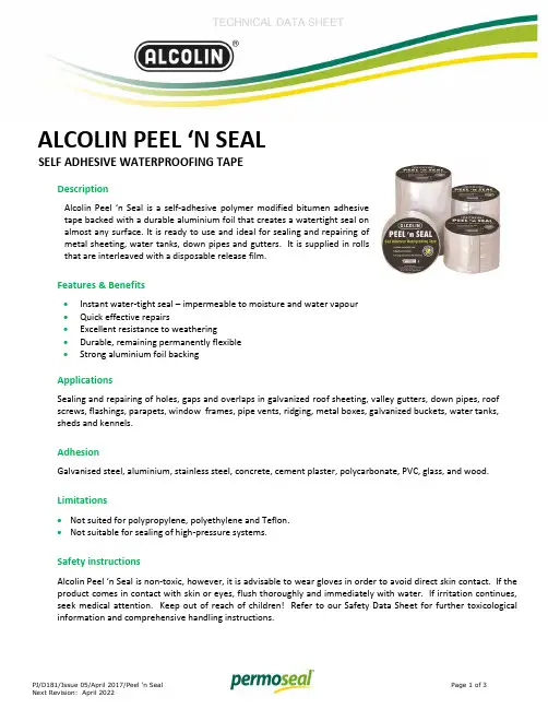
ALCOLIN PEEL ‘N SEALSELF ADHESIVE WATERPROOFING TAPEDescriptionAlcolin Peel ‘n Seal is a self-adhesive polymer modified bitumen adhesivetape backed with a durable aluminium foil that creates a watertight seal onalmost any surface. It is ready to use and ideal for sealing and repairing ofmetal sheeting, water tanks, down pipes and gutters. It is supplied in rollsthat are interleaved with a disposable release film.Features & Benefits∙Instant water-tight seal – impermeable to moisture and water vapour∙Quick effective repairs∙Excellent resistance to weathering∙Durable, remaining permanently flexible∙Strong aluminium foil backingApplicationsSealing and repairing of holes, gaps and overlaps in galvanized roof sheeting, valley gutters, down pipes, roof screws, flashings, parapets, window frames, pipe vents, ridging, metal boxes, galvanized buckets, water tanks, sheds and kennels.AdhesionGalvanised steel, aluminium, stainless steel, concrete, cement plaster, polycarbonate, PVC, glass, and wood.Limitations∙Not suited for polypropylene, polyethylene and Teflon.∙Not suitable for sealing of high-pressure systems.Safety instructionsAlcolin Peel ‘n Seal is non-toxic, however, it is advisable to wear gloves in order to avoid direct skin contact. If the product comes in contact with skin or eyes, flush thoroughly and immediately with water. If irritation continues, seek medical attention. Keep out of reach of children! Refer to our Safety Data Sheet for further toxicological information and comprehensive handling instructions.Surface preparationSurfaces to be bonded must be clean, structurally sound, dry and free from dust, dirt, oil, rust and loose material. Smooth non-porous surfaces such as metals and plastics should degreased with a solvent such as acetone or thinners. Any gaps should be filled prior to application. Poor surface preparation may result in lifting and delamination of the tape.Directions for use∙Ensure that surfaces are prepared as above.∙Unroll the tape and measure the correct length for the area to be sealed.∙Cut the tape ensuring a 40mm overlap.∙Allow the tape to warm in the sun before application.∙Peel the release paper back from one end and press the tape firmly onto the surface.∙Removing the backing tape as you proceed.∙On angles and grooves press firmly into the angle or groove first.∙For a smooth finish, press tape with a rubber hand roller, working from the center outwards, remove any air bubbles and creases ensuring firm contact is made with the surface.∙The aluminium foil backing must not be removed.Storage stabilityStore in cool place below 25°C. Recommended storage is 24 months.Product packaging∙Alcolin Peel ‘n Seal 2.5m x 50mm ∙Alcolin Peel ‘n Seal 2.5m x 75mm ∙Alcolin Peel ‘n Seal 2.5m x 100mm ∙Alcolin Peel ‘n Seal 5m x 100mm ∙Alcolin Peel ‘n Seal 5m x 150mm ∙Alcolin Peel ‘n Seal 10m x 75mm ∙Alcolin Peel ‘n Seal 10m x 100mm ∙Alcolin Peel ‘n Seal 10m x 150mmProduct datai. Physical dataii. Application dataiii. Performance dataThe above information is only offered, as a guide to the use of this product. Furthermore, users should satisfythemselves that it is suitable for their needs. Since we have no control over the conditions under which it is used, wecannot accept responsibility for problems caused by the use and/or application of this product.Head Office: +27(0)21 555 7400Toll free no: 0800 222 400 Array 1 Beverley Close, Montague GardensPO Box 37008, Chempet, 7442。
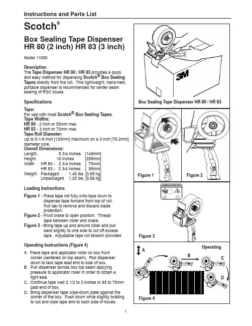
Instructions and Parts ListScotch®Box Sealing Tape DispenserHR 80 (2 inch) HR 83 (3 inch)Model 11000DescriptionThe Tape Dispenser HR 80 / HR 83 provides a quickand easy method for dispensing Scotch® Box SealingTapes directly from the roll. This lightweight, hand-held,portable dispenser is recommended for center seamsealing of RSC boxes.Box Sealing Tape Dispenser HR 80 / HR 83 Specifi cationsTape:For use with most Scotch® Box Sealing Tapes.Tape Widths:HR 80 - 2 inch or 55mm maxHR 83 - 3 inch or 72mm maxTape Roll Diameter:Up to 5-1/8 inch [130mm] maximum on a 3 inch [76.2mm]diameter core.Overall Dimensions:Length: 5 3/4 inches [145mm]Height 10 inches [255mm]Width HR 80 - 2 3/4 inches [ 70mm]HR 83 - 3 3/4 inches [ 95mm]Weight Packaged 1.45 lbs. [0.65 kg]Unpackaged 1.25 lbs. [0.56 kg]Loading InstructionsFigure 1 - Place tape roll fully onto tape drum todispense tape forward from top of roll.Pull tab to remove and discard bladeprotection.Figure 2 - Pivot brake to open position. Threadtape between roller and brake.Figure 3 - Bring tape up and around roller and pullback slightly to one side to cut off excesstape. Adjustable tape roll tension provided.Operating Instructions (Figure 4)A. Place tape and applicator roller on box frontcorner (centered on top seam). Roll dispenserdown to tack tape lead end to side of box.B. P ull dispenser across box top seam applyingpressure to applicator roller in order to obtain atightseal.C. C ontinue tape web 2 1/2 to 3 inches or 65 to 75mmpast end of box.D. B ring dispenser tape wipe-down plate against thecorner of the box. Push down while slightly twistingto cut and wipe tape end to back side of boxes.12Equipment Warranty and Limited Remedy: THE FOLLOWING WARRANTY IS MADE IN LIEU OF ALL OTHER WARRANTIES, EXPRESS OR IMPLIED, INCLUDING, BUT NOT LIMITED TO, THE IMPLIED WARRANTY OF MERCHANTABILITY, THE IMPLIED WARRANTY OF FITNESS FOR A PARTICULAR PURPOSE AND ANY IMPLIED WARRANTY ARISING OUT OF A COURSE OF DEALING, A CUSTOM OR USAGE OF TRADE:3M warrants that its Scotch ® Box Sealing Equipment will be free from defects for ninety (90) days after delivery. If any part is proved to be defective within the warranty period, then the exclusive remedy and 3M’s and seller’s sole obligation shall be, at 3M’s option, to repair or replace the part, provided the defective part is returned immediately to 3M’s factory or an authorized service station designated by 3M. A part will be presumed to have become defective after the warranty period unless the part is received or 3M is noti fi ed of the problem no later than fi ve (5) calendar days after the warranty period. If 3M is unable to repair or replace the part within a reasonable time, then 3M, at its option, will replace the equipment or refund the purchase price.Limitation of Liability: 3M and seller shall not be liable for direct, indirect, special, incidental or consequential damages based upon breach of warranty, breach of contract, negligence, strict liability or any other legal theory.The foregoing Equipment Warranty and Limited Remedy and Limitation of Liability may be changed only by a written agreement signed by authorized of fi cers of 3M and seller.Model Part NumberDescriptionHR 80 78-8137-3530-1 2" Blade/Wiper Assembly HR 83 78-8137-3531-9 3" Blade/Wiper AssemblyMinimum billing on parts orders is $25.00. Replacement part prices available on request. $10.00 restocking charge per invoice on returned parts.Outside the U.S., contact the local 3M subsidiary for parts ordering information.How To Order Replacement Parts1. Refer to parts list for correct part number.2. Order by description, dispenser name, andpart number.3. Replacement parts and part prices availabledirect from:How To Replace the Wiper and Blade Assembly 1. Remove screws to detach used wiper and bladeassembly.2. Install new wiper and blade assembly withserrated cutting edge pointing away from applicator roller.3. Replace and tighten screws to secure new wiperand blade assembly (Figure 5).3M Tape Dispenser Parts 241 Venture DriveAmery, WI 54001-1325800-344-9883Fax: 715-268-8153Replacement Parts List To reduce the risk associated withsharp blade hazards:Keep hands and cutoff blade. The blade is extremely sharp.Figure 5Replacement IllustrationIndustrial Adhesives and Tape Division 3M Center, Building 220-5E-06St. Paul, MN 55144-10001-800-362-3550/packaging“Scotch” is a trademark of 3M Company "3M" is a trademark of 3M Company,St. Paul, Minnesota 55144-1000Printed in U.S.A.© 3M 2011 44-0009-2199-9 (C042911-NA)。
Table.Spearman Correlations between CRISS and individual components at12months and Comparison of ABA and PBO using CRISS index and individual components at12 months;Outcome ABAN=44PBON=44TreatmentDifference(ABA-PBO)P-value^ACR CRISS(0.0-1.0) median(IQR)0.68(1.00)0.01(0.86)0.03 SpearmanCorrelationLSmean(SE)LSmean(SE)LS mean(SE)P-value^^D mRSS(0-51)-0.75*-6.7(1.30)-3.8(1.23)-2.9(1.75)0.10D FVC%predicted0.36*-1.4(1.30)-3.1(1.20)1.7(1.72)0.32D PTGA(0-10)-0.17-0.50(0.392)-0.30(0.385)-0.20(0.557)0.73D MDGA(0-10)-0.47*-1.34(0.282)-0.18(0.284)-1.16(0.403)0.004D HAQ-DI(0-3)-0.21-0.11(0.079)0.11(0.076)-0.22(0.108)0.05^p-value for treatment comparisons based on Van Elteren test^^p-value for treatment comparisons based on ANCOVA model with treatment,duration of SSc and baseline value as covariates*p<0.01using Spearman correlation coefficientNegative score denotes improvement,except for FVC%where negative score denotes worsening;LS mean=least squares mean;SE=standard errorFRI0328BRANCHED CHAIN AMINO ACIDSIN THE TREATMENTOF POLYMYOSITIS AND DERMATOMYOSITIS:RESULTSFROM THE BTOUGH STUDYNaoki Kimura,Hitoshi Kohsaka.Tokyo Medical and Dental University(TMDU), Department of Rheumatology,Tokyo,JapanBackground:Muscle functions of patients with polymyositis and dermato-myositis(PM/DM)remain often impaired even after successful control of the immune-mediated muscle injury by immunosuppressive therapy.The only effort at the present to regain muscle functions except for the immu-nosuppression is rehabilitation,which is carried out systematically in lim-ited institutes.No medicines for rebuilding muscles have been approved. Branched chain amino acids(BCAA)promote skeletal muscle protein syn-thesis and inhibit muscle atrophy.They thus have positive effects on muscle power,but have never been examined for the effects on PM/DM patients.Objectives:To assess the efficacy and safety of BCAA in the treatment of PM/DM for official approval of their use in Japan.Methods:Untreated adults with PM/DM were enrolled in a randomized, double-blind trial to receive either TK-98(drug name of BCAA)or pla-cebo in addition to the conventional immunosuppressive agents.One package of TK-98(4.15g)contained L-isoleucine952mg,L-leucine 1904mg,and L-valine1144mg(molar ratio is1:2:1.35),and6packages were administered daily in3divided doses.After12weeks,patients with average manual muscle test(MMT)score less than9.5were enrolled in an open label extension study for12weeks.The primary end point was the change of the MMT score at12weeks.The secondary end points were the disease activity evaluated with myositis disease activity core set (MDACS)and the change of functional index(FI),which evaluates dynamic repetitive muscle functions.Results:Forty-seven patients were randomized to the TK-98(24patients [12with PM and12with DM])and placebo(23patients[11with PM and12with DM])groups.The baseline MMT scores were equivalent (7.97±0.92[mean±SD]in the TK-98group and7.84±0.86in the placebo group).The change of MMT scores at12weeks were0.70±0.19(mean ±SEM)and0.69±0.18,respectively(P=0.98).Thirteen patients from the TK-98group and12from the placebo group were enrolled in the exten-sion study.The MMT scores in both groups improved comparably throughout the extension study.The increase of the FI scores of the shoulder flexion at12weeks was significantly larger in the TK-98group (27.9±5.67and12.8±5.67in the right shoulder flexion[P<0.05],27.0±5.44and13.4±5.95in the left shoulder flexion[P<0.05]).The improvement rate of the average FI scores of all tested motions(head lift,shoulder flexion,and hip flexion)through the first12weeks was larger in the TK-98group.No difference was found in the disease activ-ity throughout the study period.Frequencies of the adverse events until 12weeks were comparable.Conclusion:Although BCAA exerted no effects in the improvement of the muscle strength evaluated with MMT,they were effective in the improve-ment of dynamic repetitive muscle functions in patients with PM/DM with-out significant increase of adverse events.Disclosure of Interests:None declaredDOI:10.1136/annrheumdis-2019-eular.5235FRI0329ANALYSIS OF11CASES OF ANTI-PL-7ANTIBODYPOSITIVE PATIENTS WITH IDIOPATHIC INFLAMMATORYMYOPATHIES.MALIGNANCY MAY NOT BE UNCOMMONCOMPLICATION IN ANTI-PL-7ANTIBODY POSITIVEMYOSITIS PATIENTSTaiga Kuga,Yoshiyuki Abe,Masakazu Matsushita,Kurisu Tada,Ken Yamaji, Naoto Tamura.Juntendo University School of Medicine,Department of Internal Medicine and Rheumatology,Tokyo,JapanBackground:Various autoantibodies are known to be related to idiopathic inflammatory myopathies(IIM).Anti-PL-7antibody is anti-threonyl-tRNA synthetase antibody associated with antisynthetase syndrome(ASS).Since anti-PL-7antibody is rare(mostly1-4%of myositis,while a Japanese study reported17%),little is known as to clinical characteristics of it(1). Objectives:To analyze clinical characteristics of anti-PL-7positive IIM patients.Methods:Anti-PL-7antibody was detected by EUROLINE Myositis Profile 3.IIM diagnosis was made by the2017EULAR/ACR classification criteria (2)and/or Bohan And Peter classification(3).Eleven anti-PL-7antibody positive adult patients(all female),age at onset(61.5±12.6years)were enrolled in this study between2009and2018.Clinical manifestations, laboratory and instrumental data were reviewed in this single centre retro-spective cohort.Results:Characteristic symptoms were identified at diagnosis:skin mani-festations(7/11cases,63.6%),muscle weakness(8/11cases,72.7%), arthralgia(5/11cases,45.5%)and Raynaud’s phenomenon(4/11cases, 36.4%).Myogenic enzymes were elevated in most cases(10/11cases, 90.9%).ILD was detected in all patients(11/11cases,100%)and2 patients(18.2%)developed rapidly progressive rgest IIM subtype was polymyositis(PM,5/11cases),followed by dermatomyositis(DM,3/ 11cases)and amyopathic dermatomyositis(ADM,3/11cases).Five patients(45.5%)complicated with malignancy within3years from the diagnosis of IIM.Though clinical manifestations and laboratory data showed any difference between malignancy group and non-malignancy group,all3ADM cases but no DM cases complicated with malignancy in this study.Conclusion:Anti-PL-7antibody positive IIM patients frequently complicated with ILD.Frequency of cancer in ASS patients within three years from diagnosis was 1.7%and not much different from the general population in previous report from France(4).Though this study only included IIM patients and may have selection bias,careful malignancy survey may be essential in Anti-PL-7antibody positive IIM patients.REFERENCES:[1]Y Yamazaki,et al.Unusually High Frequency of Autoantibodies to PL-7Associated With Milder Muscle Disease in Japanese Patients With Poly-myositis/DermatomyositisARTHRITIS&RHEUMATISM Vol.54,No.6, June2006,pp2004–2009[2]Lundberg IE,Tjärnlund A,Bottai M,et al.EULAR/ACR classification crite-ria for adult and juvenile idiopathic inflammatory myopathies and their Major Subgroups.Ann Rheum Dis.2017;76:1955–64.[3]Bohan A,Peter J.Polymyositis and dermatomyositis.N Engl J Med1975,292:344-347;403-407.[4]Hervier B,et al.Hierarchical cluster and survival analyses of antisynthe-tase syndrome:phenotype and outcome are correlated with anti-tRNA syn-thetase antibody specificity.Autoimmunity reviews.2012;12:210–217. Disclosure of Interests:Taiga Kuga:None declared,Yoshiyuki Abe:None declared,Masakazu Matsushita:None declared,Kurisu Tada Grant/ research support from:Eli Lilly,Ken Yamaji:None declared,Naoto Tamura Grant/research support from:Astellas Pharma Inc.,Asahi Kasei Pharma,AYUMI Pharmaceutical Co.,Chugai Pharmaceutical Co.LTD, Eisai Inc.,:Takeda Pharmaceutical Company Ltd.,Speakers bureau:Jans-sen Pharmaceutical K.K.,Bristol-Myers Squibb K.K.,:Mitsubishi Tanabe Pharma Co.DOI:10.1136/annrheumdis-2019-eular.4150846Friday,14June2019Scientific Abstractson December 25, 2023 by guest. Protected by copyright./Ann Rheum Dis: first published as 10.1136/annrheumdis-2019-eular.5235 on 27 May 2019. Downloaded from。

significantly associated with RCD surgery after more than10 years of work(Ex.HR for11–20years vs.0years with static strength score 4=2.06,95%CI=1.39–3.04).Conclusion Numerous occupational physical exposures were associated with incident RCD surgery.Associations were stron-gest in workers with more than a decade of high exposure.O-240ASSOCIATIONS BETWEEN FEELING COLD AT WORK AND WORK PERFORMANCE IN A COLD-EXPOSEDWORKING POPULATION FROM THE TROMSØ6STUDY 1Morten Skandfer,Erlend Farbu Hoftun,Tormod Brenn,Anje Christina Höper.1UIT The Arctic University of Norway,Norway10.1136/OEM-2021-EPI.87Objective Cold exposure is associated with an increased preva-lence of musculoskeletal pain.We found earlier that employees spending 25%of their working time in cold environments had higher odds of chronic musculoskeletal pain.There was a consistent tendency of higher odds for increasing frequency of feeling cold.Cold exposure can also interfere with work per-formance.The aim of this study was therefore to investigate if the frequency of cold experience was associated with impaired work performance.Methods We used data from the sixth survey of the T romsøstudy(2007–2008).Participants aged30–67years who reported to work in a cold environment 25%of the time, were not retired,not receiving full-time disability benefits and without missing values were included,leading to793partici-pants.Feeling cold was categorized into never,sometimes and often feeling cold.Work performance variables comprised of binary variables of impaired control of movement,heavy phys-ical work and long-lasting physical work,finger dexterity and –sensitivity.Associations between feeling cold at work and self-reported work performance were examined with Poisson-regression,adjusted for age,sex,smoking and body mass index.Results Both prevalence of impaired work performance and associations between frequency of feeling cold and impaired work performance were consistently lower for those never feeling cold and higher for those feeling cold often,compared to those feeling cold sometimes.In the fully adjusted model, the strongest associations were found for impaired long-lasting work performance with prevalence ratio(PR)0,35(95%CI 0,20–0,62)for never feeling cold and PR1,81(95%CI1,35–2,42)for feeling cold often.For impaired heavy work PRs were0,53(95%CI0,31–0,90)and2,13(95%CI1,50–3,04), respectively.Conclusion In this cross-sectional study on cold-exposed work-ers,cold experience frequency was associated with work per-formance with the tendency of increased work impairment with increasing frequency of feeling cold.O-433WHICH QUEBEC INDUSTRIES AND OCCUPATIONS ARE AT RISK OF WORK-RELATED MUSCULOSKELETALDISORDERS?A COMPARISON OF ANALYSES OF2010–2012WORKERS’COMPENSATION AND2014–2015HEALTH SURVEY DATA1Susan Stock,Nektaria Nicolakakis,France Tissot.1INSPQ;University of Montreal,Canada 10.1136/OEM-2021-EPI.88Introduction Non traumatic work-related musculoskeletal disor-ders(WMSD)represent an enormous burden of preventable illness.T wo strategies and data sources to document this bur-den and identify workers at highest risk were compared. Objectives T o identify gender-stratified worker groups at high risk of non-traumatic WMSD by industry and type of occupa-tion and compare WC to health survey results.Methods Using2014–2015Quebec Health Survey(QPHS) data on24,300workers,measuring self-reported WMSD and industry groupings stratified by occupation(manual/mixed/ non-manual),WMSD risk for each industry-occupation group was estimated using gender-stratified adjusted regression anal-yses and estimation ing Quebec2010–2012 workers’compensation(WC)data,gender-stratified WMSD incidence rates per1,000full-time equivalent employees(‰FTEE)were calculated for174industry-type-of-occupation groups.WMSD risk was ranked according to Prevention Index scores.Results In both studies,women in manual occupations had the highest WMSD risk compared to male counterparts(WC: 39‰vs27‰FTEE;QPHS:36%vs25%);manual male and female workers in administrative/support/cleaning/garbage serv-ices were identified at high risk;as well as women in accom-modation/restaurant and men in specialised construction trades,civil engineering,and metal pensa-tion data identified another9high-risk groups for men,and 11for women including3health sector groups that ranked in the top5for women.Conversely,the QPHS identified another13high risk groups in men including several con-struction and manufacturing sectors and5in women. Discussion Differences between the2studies’results are likely due to methodologic differences,including under-reporting in compensation data and the survey’s low power to identify some industries stratified by gender and occupation.Results of the two studies are complementary and each adds to our understanding of which groups are at WMSD risk to target for prevention.Research is needed to compare different sur-vey and compensation data analytic strategies to improve capacity to identify workers at high WMSD risk.O-465PAIN IN HEALTHCARE WORKERS:A PERSPECTIVE OF MULTIDISCIPLINARY APPROACH1Simone Fargetti,Telma de Cassia dos Santos Nery,Salvador Celso Callia,Maria Thereza Toledo Penteado,Monize Mendonça Cruz,Moacyr Vergara de Godoy Moreira. 1Hospital das Clinicas HCFMUSP,Faculdade de Medicina,Universidade de Sao Paulo,Brazil 10.1136/OEM-2021-EPI.89Introduction Health professionals deal with numerous hazards during their occupational life from a physical and mental point of view:precarious working conditions,irregular work-ing hours,emotional pressure,physically demanding jobs, involving weight lifting and manual tasks,which may cause pain and musculoskeletal disorders.Our occupational health service assists more than20,000health workers in a large hospital complex in Latin America.It consists of a multidisci-plinary team involving physicians,psychologists,engineers, occupational therapists,physiotherapists,as well as an emer-gency care service where workers may seek immediate medical attention.Objective T o describe the most frequent complaints related to musculoskeletal pain in emergency medical care at our78 on December 25, 2023 by guest. Protected by copyright./ Occup Environ Med: first published as 10.1136/OEM-2021-EPI.89 on 22 October 2021. Downloaded fromoccupational medicine service and the multidisciplinary approach for referring and treating these workers.Methods This descriptive and retrospective study comprised data from the occupational emergency care service from2016 to2020.All complaints related to International Classification of Diseases(ICD10)codes M and S were analyzed.Results13,312consultations were carried out in our service from2016to2020due to ICDs M and S;73.1%workers were female,which coincides with genre distribution in our service.The leading cause of musculoskeletal pain was low back pain(M54.5),whereas finger injuries(S61.0)and ankle sprains(S93.0)were the most important complaints related to trauma.Visits related to musculoskeletal complaints were less frequent in2020compared to other years due to Covid-19 pandemics,since this service was responsible for evaluating and testing workers with respiratory symptoms.Workers with musculoskeletal complaints were referred directly from emer-gency care or occupational physician to multidisciplinary team: orthopedic surgeon,acupuncture,physiotherapy or work adjustment with occupational team.Conclusion Occupational emergency care data is an important indicator of injuries and pain in healthcare professionals.Its integration with a multidisciplinary team is essential to prevent further musculoskeletal illnesses in hospital workforce. Muskuloskeletal-2O-20PREVALENCE,PREDICTORS AND WAGE REPLACEMENT DURATION ASSOCIATED WITH DIAGNOSTIC IMAGINGIN AUSTRALIAN WORKERS WITH ACCEPTED CLAIMSFOR LOW BACK PAIN:A RETROSPECTIVE COHORTSTUDY1Michael Di Donato,Ross Iles,Rachelle Buchbinder,Ting Xia,Alex Collie.1Monash University,Australia10.1136/OEM-2021-EPI.90Introduction Diagnostic imaging is not recommended for low back pain(LBP)in the absence of clinical evidence to suggest a serious pathology is the cause of pain.Workers may access funding for wage replacement and healthcare,including diag-nostic imaging,from workers’compensation if they cannot work due to LBP.Objectives This study sought to determine in Australian work-ers with accepted workers’compensation claims for LBP(1) the prevalence of diagnostic imaging of the spine and factors associated with its use,and(2)the association between spinal diagnostic imaging events and wage replacement duration. Methods Workers with accepted workers’compensation claims for LBP longer than two weeks were grouped by whether workers’compensation funded no,single,or multiple diagnos-tic spinal imaging in the two years since reported low back pain onset.Ordinal logistic regression was used to define the demographic,occupational and social factors associated with each group.Time-to-event analysis was used to determine the association between spinal imaging and wage replacement duration.Results In the sample of30,530workers,9,267(30.4%) received single spinal imaging and6,202(20.3%)received multiple spinal imaging.Male workers and workers from the state of Victoria had significantly higher odds of multiple imaging.Socioeconomically advantaged workers and workersfrom remote Australia had significantly lower odds of multiple imaging.Magnetic Resonance Imaging was the most common imaging modality.Workers with single spinal imaging(median duration17.0weeks;HR 2.0,95%CI 1.9, 2.1)and multiplespinal imaging(median duration49.0weeks;HR4.0,95%CI3.9,4.1)had significantly longer wage replacement durationthan those with no imaging(median duration6.1weeks). Conclusions Over half of Australian workers with an accepted workers’compensation claim for LBP longer than two weeks received diagnostic spinal imaging.Receipt of diagnostic imag-ing,particularly multiple imaging,was associated with longerwage replacement duration.O-202WORKERS ON PROLONGED WORK DISABILITY FORMUSCULOSKELETAL DISORDERS DO NOT WORRY FORNOTHING1Marie-France Coutu,Marie-JoséDurand,Fergal O’Hagan,Patrick Gosselin,Iuliana Nastasia,Djamal Berbiche,Marie-Elise Labrecque,Sara Pettigrew.1Universitéde Sherbrooke,Canada10.1136/OEM-2021-EPI.91Introduction Workers worry during prolonged work disability,but do their worries relate to their actual work disability situation?Objective The aim of this study was to assess worries andtheir maintaining factors,while considering the margin of maneuver/leeway at work and their impact on return to work (RTW).Methods We conducted a cohort study with a convenience sample of79(39men and40women)workers having persis-tent( 3months)work-related musculoskeletal disorders caus-ing absence from their regular work.Following Dugas’theory validated self-administered questionnaires(ex.:intolerance of uncertainty,utility of worrying)were completed at the begin-ning and the end of the work rehabilitation program.Also,the questionnaire on type of worries(QTW)assessed specifictypes of worries and their relationship to work.T rained occu-pational therapists,(n=16)evaluated the margin of maneu-ver of all workers.Multivariate analyses were performed onRTW predicted by workers’indicators and occupational thera-pists’margin of maneuver.ResultsT wenty-one workers did not RTW The model predicted54%of the variance in N-RTW(p.0001).Significant factors explaining N-RTW were:lack of a margin of maneuver(OR=8.5;p=.008);high intolerance for uncertainties(OR=1.12;p=.01),perceived utility of worrying(OR=1.11;p.001),and for the QTW scores,a high mean intensity of wor-ries(OR=2;p=.004)emerging from actual situations(OR=17.15;p=.02)occurring at work(OR=8.5).A posthoc analysis(pseudo R2=.33;p=)shows that a lack of a mar-gin of maneuver is associated with QTW scores of worries emerging from uncertainties at work.Conclusion Workers not returning to work worry about actual situations at work,but this is also associated with low marginof maneuver,assessed by occupational therapists.Thus,RTW interventions should focus on the work environment.78on December 25, 2023 by guest. Protected by copyright./ Occup Environ Med: first published as 10.1136/OEM-2021-EPI.89 on 22 October 2021. Downloaded from。
电工使用胶带指南很多客户把电工胶带和电工胶布和塑料胶布都叫胶布。
其实电工绝缘胶带包括很广泛:一类是:电工黑胶布(它的使用面积很广,缠电压不超过380伏的电线接头。
二类是:PVC电气胶带(俗称:塑料胶带)主要用于室内外电线接头及汽车配线包扎及电子零件的绝缘防护。
用于电压不超过600伏。
第三类:是橡胶绝缘自粘带(也称高压自粘带)用于电线电缆接头及高压绝缘防护产品的附件。
一般用于电压在1-10千伏之间或30千伏以下的绝缘密封保护。
其特性:耐高压、密封及绝缘防水。
阻燃胶带的原理及性能我公司生产有专门的阻燃醋酸布胶带等阻燃胶带,就其原因在于在胶水中添加了阻燃剂。
阻燃剂主要是从以下几个方面起阻燃作用:1、稀释效应。
稀释压敏胶中可燃物的浓度和燃烧过程中氧的浓度;2、隔热效应。
在燃烧过程中产生不良气体或泡沫层,或形成一层液体抑或固体的覆盖层,使火焰与氧气隔离;3、冷却效应。
吸收在燃烧时释放的热量,使物质温度下降,从而阻止聚合物继续降解或裂解,使挥发性气体的来源中断;4、消除效应。
通过钝化作用,消除燃烧过程中等自由基,使燃烧过程的链反应中断。
LED胶带特点的实际工业应用LED胶带主要应用于LED点阵块,数码管(LED)、显示器封口,在LED的环氧树脂灌装及高温固化过程中,起封口保护作用,有透明或绿色,易看清反射盖上的杂物。
产品具有良好的耐化学性和耐候性,使用后剥离无残胶,不渗漏,并且在产品表面产生特殊的雾面效果,产品符合ROHS环保要求,高性价比,在使用上完全可以替代进口。
布基胶带的构成原理布基胶带是在BOPP原膜的基础上经过高压电晕后使一面表面粗糙后涂上胶水后经过分条分成小卷就是我们日常使用的胶带。
胶带胶水是丙烯酸脂胶水,又叫压敏胶,主要成分是酊脂。
酊脂是一种高分子活动物质,温度高低对分子活动有一定影响。
胶水的酊脂含量直接影响到胶带的使用情况。
正常的封箱胶带的初粘力在≥13号(钢球号)之间,这种胶带胶水的厚度一般为22微米。
WATER-ACTIVATED TAPESIntertape Polymer Group | 100 Paramount Drive | Suite 300 | Sarasota, FL 34232Most pressure-sensitive tapes take time to develop a “destructive” bond when applied to a porous substrate surface. Water-activated tapes bond instantly to both virgin and recycled fiber (corrugated carton, paper, etc.) surfaces and therefore, generate an immediate destructive bond resulting in a tamper evident package.Different situations call for different carton sealing systems.Intertape® brand water-activated tapes are specifically designed for each individual application. Our reinforced products are available in non-printed, stock prints and custom print grades. They all have one common feature...uncompromising quality.The Industry Leader in High Performance Water-Activated TapesSealing lightweight or standard sized packages or cartons that will be shipped in unitized loads or full pallets.Sealing overstuffedcartons, recycled cartons,non-unitized cartons, and heavyweight cartons.PAPER TAPESREINFORCED TAPES7Enhance productofferings to end-user, making their product standout from the competition.9Sealing manufacturer’s joints or corrugated cartons in a box-making factory.9Help prevent theft, pilferage, and contamination.A DVANTAGES• Provides tamper-evident seal• Difficult to remove without leaving obvious signs of tampering • Easy to print on• Retains integrity if punctured • One strip produces a sturdy seal!• Recyclable with the carton to which it isapplied10Machines that can outputwater-activated tape faster and easier than ever before.B ENEFITSDesigned for fast, permanent adhesion and superior strength. Cracking of the adhesive surface provides our paper tape with excellent flexibility for sealing carton corners, edges and irregular surfaces. Use Intertape ® brand paper tapes to seal lightweight or standard sized packages or cartons that will be shipped in unitized loads or full pallets.All product grades available in other sizes upon request.• Aggressive Bond — our starch-based adhesive aggressively bonds to corrugated cartons, even in dusty or dirty environments.• Available in Various Colors & Patterns — ideal for organizing your stock and rotating your inventory.• Custom Printing — advertise your company and• Certified Recyclable —Water-Activated Paper Tape (unreinforced) has passedWestern Michigan University OCC Equivalency testing protocol.• Curbside Recyclable —PAPER TAPESB ENEFITS• Secure Bond — testing proves our tape bonds faster than any competitor’s of like construction.• All Weather Use — not affected by extreme hot or cold temperatures.• Superior Strength — fiberglass yarns seal your cartons with an extra measure of strength.• Takes on the Dust —absorbs dust and bonds securely to the carton. Sealing the seam also acts as a dust barrier.• Pilferage Proof —damaged upon tape removal.• Curbside RecyclableCurby line, the paper fibers in water activated tape are recycled when theAvailable in a wide variety of sizes and product construction, Intertape brand reinforced tapes are designed to provide consistent performance in carton sealing applications where durability, extra strength and reliability are required. Extra strong fiberglass yarns are bonded between the high tensile strength sheets for an extra margin of strength.STYLE DESCRIPTION WIDTHS TOP/BOTTOMPAPER WEIGHT COLORS BASIS REINFORCEMENT ROLLS PER CASE CASESPERPALLET mm lbs/lbsMedallion Recommended uses: Two strip cartonsealing (top & bottom), recycled cartons,non-unitized loads, light to averageweight carton up to 30 lbs.70727623/2325/23NaturalWhiteMD - (1-1-1-1-1) 75fiberglass on 13mmspacingCD- (1-1-1) Polyester1.10” spacing70mm - 114m - 8 PACK8470mm - 137m - 10 PACK6370mm - 183m -10 PACK 6072mm - 500' -6 PACK6076mm - 114m - 8 PACK8476mm - 137m - 10 PACK63Legend Recommended uses: Two strip cartonsealing (top & bottom), recycled cartons,non-unitized loads, light to averageweight carton up to 25 lbs. Available forcustom printing.60707223/2325/23NaturalWhiteMD - (1-1-1-1-1) 110fiberglass on 13mmspacingCD - (1-1-1) Polyester1.10" spacing60mm - 137m - 12 PACK6370mm - 137m - 10 PACK6370mm - 152m - 6 PACK8470mm - 183m- 10 PACK60Venom Recommended uses: Two strip cartonsealing (top & bottom), recycled cartons,non-unitized loads, light weight cartonsup to 24 lbs.7020/23NaturalMD - (1-1-1-1) 110fiberglassCD - (1-1-1) Polyester1.10" spacing60mm - 137m - 12 PACK6370mm -137m - 10 PACK6370mm- 152m - 6 PACK8470mm - 183m - 10 PACK60REINFORCED TAPES REINFORCED TAPESSTYLE DIAGONAL STRIPESAdd a QR Code toyour custom print to promote any facet ofyour business!STYLE GRADE COLORS WIDTH x LENGTH ROLLS PER CASECASES PER PALLETinches feet K7450P144#260 Reinforced Red 34501063K7453P795#260 Reinforced Green 34501063K7453P797#260 Reinforced Yellow 34501063K2763P001#260 Reinforced Bright Green34501063K2125P047#160 Medium Duty Paper Red 2.56001260K2876P581#160 Medium Duty Paper Green 2.56001260K2202P032#160 Medium Duty Paper Yellow 2.56001260K2876P580#160 Medium Duty Paper Orange 2.56001260K2799P615#160 Medium Duty Paper Pale Blue 2.56001260K2800P756#160 Medium Duty Paper Red 36001060K2867P624#160 Medium Duty Paper Green 36001060K2867P621#160 Medium Duty Paper Yellow 36001060K2867P623#160 Medium Duty Paper Orange 36001060K2800P713#160 Medium Duty PaperPale Blue36001060SOLID COLORSPRINTED TAPEScartons, in addition to virgin board. Available in long length rolls, the Box Maker’s tapes accommodate continuous application, work on small to large carton joints and improve productivity. All Purpose tape (281 Grade) is available in natural, and white colors.Product specifications are available from your Packaging Specialist or IPG’s Technical Service Department.Central has two grades of quality Box Maker’s tapes:••WAT TABLE TOP DISPENSERSBetter Pack® 555e Series• Highly Productive, Durable and UL Listed• Created for fast-paced packaging environments where increased productivity, efficiency and carton sealing output is needed Better Pack® 333 Plus• World’s #1 selling Manual WAT Tape Dispenser• Perfect for light-to-medium -volume packaging areas and accommodates both reinforced and non-reinforced tapesRSA 2024-WAT (Random AUTO H2O® WAT Case Sealer)• Designed to process different sized cases using industrial sized water-activated rolls• Ergonomic and user-friendly operation • Fast processing rate of 10-12 cases/minIPG® has developed machines that address all your previous unfulfilled needs in the market. Closing cartons with water-activated tapes has become fasterand easier. Better Pack ® is a leading brand in water-activated tape dispensers thanks to unmatched innovation, quality, design, and reliability. Interpack™ is a brand of case sealers that can output high speeds, needs low maintenance, and possesses low cost.BETTER. Print a custom marketing message and/or QR code to drive your brand.FASTER. Only 1 strip is needed to secure each end of a box versus 2 or more strips of regular packing tape.WATER-ACTIVATED TAPEONESTRIP OF TAPEMULTIPLESTRIPS OF TAPE(on top and bottom)(on top and bottom)DO IT RIGHT!FIRST TIME. EVERY TIME.CORPORATE PROFILEIntertape Polymer Group® Inc. (IPG®) is a recognized leader in the development, manufacture and sale of a variety of paper and film based pressure-sensitive and water-activated tapes, stretch and shrink films, protective packaging, woven and non-woven products and packaging machinery for industrial and retail use. Headquartered in。
O PERATING I NSTRUCTIONS AND T ROUBLE S HOOTING G UIDE21-1083 02-06 NAD-31514-2Thank you for purchasing Firestone air helper springs. You have purchased a quality product from the world's number one air spring manufacturer.This manual will provide answers to some of your questions regarding the use and operation of your new air helper springs. Following the guidelines in this manual will help provide you with many years of trouble-free service from your Firestone air helper springs.F IRESTONE I NDUSTRIAL P RODUCTS C OMPANY310 E. 96TH . S TREET I NDIANAPOLIS , IN 462401-800-888-0650TMFor vehicle applications, air pressure requirements, air compressor CFM,maintainance, or air spring technical data,visit us on the web at:(2071 Shown)(2320 Shown)G ENERAL INFORMATIONFirestone air helper springs are heavy duty, quality air springs designed to supplement your vehicle's existing suspension system. These durable air springs allow you to maximize your vehicle's load carrying capacity through the use of air pressure. Proper installation, use, and operation will provide the maximum service life and performance your air spring kit is capable of delivering. These instructions will help you obtain the maximum benefits available from your air spring kit.R IDE-R ITE™AIR HELPER SPRINGSRide-Rite™ air helper springs are installed between the frame and the suspension of light trucks, vans, and motorhomes. Ride-Rite™ air helper springs are capable of carrying loads up to 5000 lbs (do not exceed the vehicle's GVWR).S PORT-R ITE™AIR HELPER SPRINGSSport-Rite™ air helper springs are installed between the frame and suspension of light trucks, and utilize a sleeve-style air spring to enhance the ride when the vehicle is loaded or unloaded. Sport-Rite™ air helper springs are capable of carrying loads up to 3000 lbs (do not exceed the vehicle's GVWR).B ASIC OPERATIONAs your vehicle is loaded, the stock suspension is compressed under the weight of the load. Your vehicle's stock suspension system has been designed so that it will provide optimum performance and handling with a specific load on the vehicle. When your vehicle is loaded, its performance, handling characteristics, and ride quality may be compromised. As the stock suspension is compressed, the ride may become "mushy", and you may encounter sway and handling problems. As weight is added to the vehicle, the air helper springs become an active part of the suspension system. As more air pressure is added to the air springs, they will support more weight. You will be able to compensate for a heavy load by adding air pressure to the air springs, thereby reducing sway and handling problems associated witha heavily loaded vehicle.S ETTING UP YOUR AIR SPRING SYSTEMAfter installing Ride-Rite™ / Sport-Rite™ air helper springs to your vehicle, or after purchasing a vehicle equipped with Ride-Rite™/ Sport-Rite™air helper springs, take a few minutes to establish some basic operating guides. Following these guidelines will ensure optimum performance from your air spring kit:T ORQUE SPECIFICATIONSUsing a torque wrench, torque the threaded fasteners to the following specifications:•Fasteners used on studs and blind holes in air springs10 - 15 ft lbs•Hex nuts installed on axle straps10 - 15 ft lbs•Hex nuts installed on 3/8" hex bolts28 - 32 ft lbs•Hex nuts and bolts used to secure brackets to frame28 - 32 ft lbs•Hex nuts installed on U-bolts15 - 20 ft lbs•Hex bolts securing 110/70 air spring to lower bracket10 - 12 ft lbsP REVAILING-TORQUE LOCK NUTSIn order to assure trouble-free operation, your air spring kit includes a variety of self-locking threaded fasteners. Your kit may include prevailing-torque lock nuts. Prevailing-torque lock nuts may be more difficult to install, but will not come loose under normal suspension operation.T HREAD LOCKING COMPOUNDThe hex bolts used to secure the air spring to the brackets may have a locking compound applied to the threads. Lock washers are not required when using a fastener with pre-applied thread locking compound. When installing fasteners with thread locking compound, follow the torque recommendations listed above.H ELICAL LOCK WASHERSYour air helper spring kit may include helical lock washers. In order to properly use the lock washer, tighten the nut/bolt fastener just enough to flatten the lock washer. Overtightening the fastener may damage the nut or bolt. When using helical lock washers, follow the torque recommendations listed above.2A IR FITTINGSYour kit will include one of two types of push-to-connect air fittings. Ride-Rite™ kits include push-to-connect air fittings with a thread locking compound pre-applied to the fitting's threads. Sport-Rite™ kits include push-to-connect swivel fittings with a nylon collar in place of the thread locking compound.Ride-Rite™ fittings - To install the air fittings with the pre-applied thread sealant, thread the air fitting into the air spring and tighten the fitting securely to engage the pre-applied thread sealant.Sport-Rite™ fittings - To install the air fittings with the nylon collar, thread the air fitting into the threaded hole on the air spring so that the nylon collar makes contact with the top of the air spring and then tighten 1/4-1/2 turn. No thread sealant is required.Both types of air fittings allow easy connection between the air fitting and the air line tubing. To install the air line in the fitting, cut the tubing as square as possible using a sharp utility knife or razor blade. Push the air line into the fitting as far as possible. If the tubing must be removed from the fitting, first release the air pressure from the air spring. Push the collar towards the body of the fitting and then pull the tubing out.P RESSURE DIFFERENTIAL BETWEEN AIR SPRINGSIt is not uncommon to have a pressure differential between the air springs after the vehicle has been brought to a level condition. If the vehicle is within the manufacturer's recommended gross vehicle weight and you have not achieved a level condition after inflating the air springs to 80 psi, there may be a problem with your stock suspension. The leaf springs may have become fatigued over time or a leaf spring may be fractured. There may be an obstruction in the air system, not allowing the air pressure to reach the air helper springs.A IR SPRING ALIGNMENTUpon completion of the installation, the air springs should be inspected for proper alignment. Although the air helper springs can function with some misalignment, it is preferred that the air springs be mounted so that they are as aligned as vertically as possible.A IR SPRING DESIGN HEIGHTCheck the distance between the upper bracket and lower bracket (design height). The dimensions shown on Page 5 are a guide to assist in determining the ideal operating height for your air helper springs.I NFLATING THE AIR SPRINGSWith the air helper springs installed on your vehicle and the vehicle sitting on a level surface, visually verify that the vehicle is in a level state. If the vehicle is not level (front-to-back or from side-to-side) it can be brought to a level position by inflating the air springs using an air source equipped with an air chuck. (If your vehicle is equipped with a cab control or automatic height control system, refer to that device's installation instructions.) Each air spring has a separate inflation valve. To level the vehicle from front-to-back, add air pressure to both air springs in equal amounts. To level the vehicle from side-to-side, add more air pressure to the air spring on the lower side of the vehicle. When inflating the air springs, add air pressure in small quantities, checking the pressure frequently. The air spring requires much less air volume than a tire, and therefore, will inflate much more quickly. Warning: DO NOT EXCEED 100psi IN EACH AIR SPRING.L EVELING THE VEHICLETake your loaded vehicle to your local service station and park on a level spot near the air pump. Check the level of your vehicle visually.If it is not level, either from front to back or from side to side, level it by inflating your air springs. (If your vehicle is equipped with a cab control unit or automatic control system refer to the directions for that device.) There is one inflation valve for each air spring. To level from front to back, add air pressure to both air springs equally. For side to side, add air pressure to the air springs on the side of the vehicle that is low. When adding air pressure to the air springs, remember that they have a much smaller volume of air that a tire so they will inflate much quicker. Add air pressure in short bursts until the vehicle is level. (NEVER EXCEED 100psi IN EACH AIR SPRING.) S TORAGEWhen storing an RV over long periods of time, inflate the air helper springs to 80 - 90 psi. The air springs will carry some of the vehicle's weight and reduce leaf spring fatigue during storage.S AFETY TIPSNever exceed the manufacturer's recommended Gross Vehicle Weight Rating (GVWR)As with your vehicle's tires, an air helper spring is a pneumatic device that supports a portion of the vehicle's weight. The air helper spring may fail as a result of punctures, impact damage, improper inflation, improper installation, or improper usage. To reduce the risk of failure, we strongly recommend the following:31. Inspect the inflated air springs to verify that they do not contact any component of the vehicle under normal suspensionoperation. The air helper spring must flex and expand during normal operation. There must be at least 1/2" of clearance between the inflated air spring and any other component of the vehicle under normal suspension operation.2. Inspect the air line tubing and the air spring to verify that they have not been damaged due to exposure to heat from the exhaustsystem. If the distance between any portion of the air spring and the exhaust system is less than 6", a heat shield should be used.3. Never overload your vehicle. The manufacturer's gross vehicle weight rating (GVWR) is stated on the specification plate on thechassis. You should weigh your vehicle on a truck scale when it is fully loaded and in a level condition to determine if your are exceeding the manufacturer's recommended GVWR.4. Never inflate the air helper springs beyond 100 psi.5. Never attempt to remove any component of the air spring assembly when the air springs are inflated.6. If an air helper spring has failed while you are on the road, operate your vehicle at reduced speeds. High speed over rough roadswill result in severe bottoming of the air spring and may damage other vehicle components.7. Never attempt to drive the vehicle in an un-leveled condition. Failure to level a heavily loaded vehicle may result in excessivebody roll and possible damage or injury.8. If unidentifiable problems exist with your air helper spring kit, visit Firestone on the web at for technical assistance.9. Never cut, weld, or modify the air helper springs or brackets.10. Do not use aerosol tire repair products in the air helper springs. If there is a hole in the air spring it must be replaced.11. Do not use a tire patch of any kind on the air helper spring. If there is a hole in the air spring it must be replaced.M AINTENANCEThe following will help obtain the maximum service life from your air helper springs:1. It is considered normal for air helper springs to lose some air pressure over time. Normal pressure loss should not exceed 3 - 4 psi perweek when the air springs are inflated to 50 psi. If the pressure loss is greater than 3 - 4 psi per week, there may be a leak in the system.Each time you check the pressure in the air springs, you will lose 3 - 5 psi. The air pressure should be checked at regular intervals. Establish an interval to check the air springs by first inflating them to the pressure required for your application. Check the air pressure after one week. If there is no pressure loss, check the air pressure after two more weeks. Again, if there is no pressure loss, check the air pressure after three more weeks. Continue to lengthen the time period until you detect a loss in air pressure. The time it takes to lose air pressure will determine how often you should check the pressure in the air springs.It is recommended that the air pressure be checked according to the following guidelines:A. When the vehicle is removed from long-term storageB. At regular intervals during the continuous operation of the vehicle (see above)C. If the air springs are used to assist in leveling an RV or camper on uneven ground, ensure that the vehicle is returned to a levelride height before departing.3. The brackets used to secure the air helper spring to the vehicle should be inspected periodically for damage and for loose fasteners. Ensurethat the air line tubing is clear of any sharp edges and routed away from the exhaust system. The brackets and air line tubing should be inspected every 6 months. Ensure that the threaded fasteners are torqued to the specifications listed on Page 2.4. Accumulated sand, gravel, or other road debris on the air springs or brackets should be rinsed away with a garden hose each time thevehicle is washed.5. If it is necessary to lift the vehicle by the frame, first release the air pressure from the air springs. This will allow the air springs to extendto their maximum length without being damaged. The uninflated air springs are capable of supporting the weight of the axle when the vehicle is lifted by the frame. After servicing of the vehicle is complete, lower the vehicle to the ground and reinflate the air helper springs to the desired pressure. On Sport-Rite kits the air helper springs must be aired up to 50 psi and then release the air until the air helper springs are to the desired pressure.T ECHNICAL DATAProper installation of the air helper spring kit is important to obtaining all of the benefits your kit is capable of delivering. The air spring must be attached to the vehicle so that it is aligned as close to vertical as possible. The air spring kit must be installed so that the distance between the upper and lower brackets is within a specific range. Refer to the chart on page 5 to determine the proper air spring mounting height and air pressure range for your application.4designed to work with the original suspension and within the manufacture’s Gross Vehicle Weight Rating (GVWR) for the intended vehicle. Brackets and air springs should not be interchanged or modified.568Air CommandWR1-760-2047 (1/2 gallon air tank)WR1-760-2232 (1 gallon air tank)The Air Command system provides a reliable source of compressed air to inflate your air springs using a heavy duty compressor, 1/2 or 1 gallon air tank, and 25' extension hose.Single Automatic Air CommandWR1-760-2186The Single Automatic Air Command kit inflates both air springs equally through the use of height control valve mounted between the chassis and suspension. (Use in conjunctionwith 2047, 2232, or 2239)Dual Air Command IIWR1-760-2168 (white face gauge)The Dual Air Command II provides front-to-rear or side-to-side leveling through the use of a dual gauge, heavy duty compressor (9210)and 1/2 gallon air tank. Inflates each air spring individually. (two air springs)Remote Fill Station WR1-760-2239The all new Remote Fill Station offers an on-board air source for inflating air springs, tires and other pneumatic components. Ideal for off-road enthusiasts and tow vehicles.Level Command IIWR1-760-2158 (white face gauge)The Level Command II kit provides inflation control of the air helper springs from inside the cab and includes a standard duty air compressor that provides equal inflation to the air springs.T HANK YOU FOR USING R IDE -R ITE ™ / S PORT -R ITE ™ AIR HELPER SPRINGS FROM F IRESTONE.T ELEPHONE : 317-818-86001-800-888-0650F AX : 317-818-8645Level CommandWR1-760-2097 (white face gauge)The Level Command kit provides inflation control of the air helper springs from inside the cab and includes a heavy duty air compressorthat provides equal inflation for both air springs.As an option, Firestone has made a variety of A ir A ccessory Systems available to use in conjunction with your air helper springs.The Air Accessory System providesinstant adjustment of your air helper springs. Some of the Air Accessory System options are shown below.© 2006 Firestone Industrial Products CompanyDual Air Command IIIWR1-760-2198 (white face gauge)The Dual Air Command III provides front-to-rear or side-to-side leveling through the use of a dual gauge, super heavy duty compressor (9230) and one gallon air tank. Inflates eachair spring individually. (two air springs)。
Scotch®Performance Flatback Tape3M2525Technical DataProduct Description Scotch®Performance Flatback Tape 2525 is used in holding, splicing or masking applications where high adhesion strength, high temperature capability and high backing strength are required.Typical PhysicalPropertiesNote: The following technical information and data should be considered representativeor typical only and should not be used for specification purposes.ASTM Test Method Adhesion to Steel: 69 oz./in. width (75 N/100 mm) D-3330Tensile Strength: 49 lbs./in. width (858 N/100 mm) D-3759 Elongation at Break: 2% D-3759Tape Thickness: 9.5 mils (0.241 mm) D-3652 Temperature Use Range: Up to 300°F (149°C)Feature•Has excellent adhesion and backing strength levels and is resistant to moistconditions.•Can be used for applications where a colored backing is desired and willwithstand a bake cycle of 300°F (149°C) for one hour.•Not recommended for outdoor applications or prolonged periods of sunlightexposure as tape may become very difficult to remove.Application Ideas•Can be used in many holding, masking and splicing applications where a highvisibility tape is desired. It can also be used for various types of edging andbinding applications.StorageStore under normal conditions of 70°F (21°C) and 50% R.H. in the original carton.Shelf LifeTo obtain best performance, use this product within 12 months from date ofmanufacture.Product UsAll statements, technical information and recommendations contained in this document are based upontests or experience that 3M believ es are reliable. However, many factors beyond 3M’s control can affectthe use and performance of a 3M product in a particular application, including the conditions underwhich the product is used and the time and environmental conditions in which the product is expected toperform. Since these factors are uniquely within the user’s knowledge and control, it is essential that theuser evaluate the 3M product to determine whether it is fit for a particular purpose and suitable for theuser’s method of application.Warranty andLimited RemedyUnless stated otherwise in 3M’s product literature, packaging inserts or product packaging for individualproducts, 3M warrants that each 3M product meets the applicable specifications at the time 3M ships theproduct. Individual products may have additional or different warranties as stated on product literature,package inserts or product packages. 3M MAKES NO OTHER WARRANTIES, EXPRESS OR IMPLIED,INCLUDING, BUT NOT LIMITED TO, ANY IMPLIED WARRANTY OF MERCHANTABILITY OR FITNESSFOR A PARTICULAR PURPOSE OR ANY IMPLIED WARRANTY ARISING OUT OF A COURSE OFDEALING, CUSTOM OR USAGE OF TRADE. User is responsible for determining whether the 3M productis fit for a particular purpose and suitable for user’s application. If the 3M product is defective within thewarranty period, your exclusive remedy and 3M’s and seller’s sole obligation will be, at 3M’s option, toreplace the product or refund the purchase price.Limitation of LiabilityExcept where prohibited by law, 3M and seller will not be liable for any loss or damage arising from the3M product, whether direct, indirect, special, incidental or consequential, regardless of the legal theoryasserted, including warranty, contract, negligence or strict liabilityThis Industrial Adhesives and Tapes Division product was manufactured under a 3M quality system registered to ISO 9001:2000 standards。
How does the wine get into the bottle in a stable and safe way?In wine production, bottling isconsidered to be particularly crucial for achieving the highest quality and cost-effectiveness. This is because it not only includes the final quality assurance step, but also determines the quantity of wine that will be sold. In order to meet the high market demands in terms of safety andservice life, the filtration process must operate seamlessly.Membrane filter cartridges are often used for quality assurance in bottling filtration. Also known as "police filters," they ensure that microorganisms harmful to wine, such as yeasts and bacteria, are retained before the wine is bottled. However, clogged or damaged membrane filter cartridges can lead to production downtime and thus to loss of revenue.To avoid this, two aspects are particu-larly essential in filter cartridge man-age m ent. First is correct pre-filtration, which prevents the membrane filter cartridges from early clogging.Secondly, regular regeneration and sterilization so that they can be safely re-used.During sterilization, microorganisms deposited on the surface of the membranes and all other product-contacting parts of the filtration system are eliminated. Thus, sterili-zation contributes significantly to the microbiological stability of the wine and the economy of the entire filtration process.Steam sterilization is the most effi-cient method of eliminating micro-organisms. In the SIP (sterili z ation in place) process, the complete cartridge housing is sterilized on site with saturated steam without having to remove the filter cartridges.There are a few aspects to consider during steam sterilization to protect the membranes and plastic compo-nents of the filter cartridges from damage due to deformation and other defects.Take advantage of Eaton's expert knowledge for safe and economical filter cartridge management.A Guide to Sterile Wine FiltrationFiltration ProductsIn SIP cleaning, all parts of the filtration system that come into contact with the product are sterilized.Sterile Membrane FiltersEnsure Wine QualityApplication BriefIn preparation for steam sterilization, the filtration system is drained and the hot saturated steam ispre-filtered so that it is free of rust, lime and particles.When all valves are opened, the heating phase of the filtration system begins. Temperature andpressure slowly build up due to the incoming saturated steam, completely displacing the condensateas it is discharged at the lowest point on the inlet and outlet sides. At a temperature between 105and 121°C, the steam outlet is throttled at all outlet valves and the actual steam sterilization begins.The membrane filter cartridges and all other product-contacting parts of the filtration system arenow sterilized for 20 to 30 minutes, depending on the temperature. It is important to note that mem-brane filter cartridges are always steamed in the direction of flow and that the maximum differentialpressure of 0.3 bar is maintained during sterilization.The filtration system is cooled down gently after steam sterilization to protect the membrane filtercartridges from damage.For this purpose, Eaton recommends allowing oil- and water-free compressed air to flow along thefilter cartridges at a maximum of 1.0 bar until a temperature of approx. 60°C is reached and thencontinuing to cool slowly with filtered cold water. Alternatively, rinsing with filtered hot water(75 to 80°C) followed by cold water is possible.As the membrane filter cartridges are exposed to high temperature fluctuations during sterilization,their integrity must be ensured by an integrity test after each sterilization cycle.What Matters in Steam Sterilization?Tips to protect filter cartridgesfrom damage and defects:• D o not clamp filter cartridgestoo tightly in the filter housingvia the counter plate.• O bserve the manufacturer's instructionson maximum temperatures, pressuredifferences and times.• C ool the filter cartridges gentlywith filtered compressed air.BECO ControlMini integritytest unitChecking integrity ofmembrane filter cartridgesBECO MAX2integritytest unitGentlecooldownoffiltrationsystemIntegrity testFor more information on proper filter cartridge management, refer to Eaton’s Filter Cartridge Manual.Compressedair filtrationWaterfiltrationBECO®MEMBRAN H Airmembrane filtercartridgesBECO PROTECTor BECOMEMBRAN PSfilter cartridgesFiltration of service mediaOptimumsteam temperature:105–121°CMax. differential pressure:0.3 barDuration:20–30 minutesSterilization of membrane filtercartridges and systemSteam sterilizationBECOPROTECT®KMdepth filtercartridgesSteamfiltrationFiltration of service mediaRemoval of particlesRemoval of particlesand microorganismsFinalwinefiltrationActive membrane protection Active membrane protectionMaximum process safety Maximum process safetyStep 4Step 3Step 2Step 1For more information, pleaseemail us at********************or visit /filtration© 2023 Eaton. All rights reserved. All trademarksand registered trademarks are the property of theirrespective owners. All information and recommenda-tions appearing in this brochure concerning the use ofproducts described herein are based on tests believedto be reliable. However, it is the user’s responsibilityto determine the suitability for his own use of suchproducts. Since the actual use by others is beyond ourcontrol, no guarantee, expressed or implied, is madeby Eaton as to the effects of such use or the resultsto be obtained. Eaton assumes no liability arising outof the use by others of such products. Nor is the infor-mation herein to be construed as absolutely complete,since additional information may be necessary ordesirable when particular or exceptional conditions orcircumstances exist or because of applicable laws orgovernment regulations.North America44 Apple StreetTinton Falls, NJ 07724Toll Free: 800 656-3344(North America only)Tel: +1 732 212-4700Europe/Africa/Middle EastAuf der Heide 253947 Nettersheim, GermanyTel: +49 2486 809-0Friedensstraße 4168804 Altlußheim, GermanyTel: +49 6205 2094-0An den Nahewiesen 2455450 Langenlonsheim, GermanyTel: +49 6704 204-0Greater ChinaNo. 7, Lane 280,Linhong RoadChangning District, 200335Shanghai, P.R. ChinaTel: +86 21 2899-3687Asia-Pacific100G Pasir Panjang Road#07-08 Interlocal CentreSingapore 118523Tel: +65 6825-1620EN03-2023。
升辉包装实业有限公司产品说明书
1、铝箔胶粘带
铝箔胶粘带是以铝箔为基材, 涂以丙烯酸型(式或橡胶型) 压敏胶, 再复以单面防粘牛皮纸制造而成, 广泛用于冰箱、空调、冷暖气管的包托及电子工业上。
2、牛皮纸胶
粘带是以牛皮纸为基材, 涂以热溶胶型(或橡胶型) 压敏胶制造而成, 主要用于纸箱包装及要求剥开PE层进行加工的场合。
3、双面胶粘带
是在基材的两面涂上压敏胶, 再复上易剥离的离型纸制造而成, 广泛用于两物体的粘接和固定, 使用十分方便.
4、聚酰亚胺
为基材涂布耐高温硅胶而成, 粘性佳,服贴性好,耐高温, 耐溶剂, 不渗锡,不残胶.。
用于电子工业中, 印刷线路板镀金手指,热风锡孔加工及过锡炉中各阶段遮蔽保护。
5、 3M胶带
特别适用于金属加强筋的固定与粘接
6、铝薄胶带
特性: 以纯铝箔为基材, 剥离强度高, 初粘性好, 内聚力强, 耐候性好, 耐高低温性能好。
使用:主要用于电冰箱、冷冻设备及保温工程的外包装
7、美纹胶带
材质: 美纹纸, 橡皮胶。
特征: 粘度适中, 不残胶, 不损毁纸张表面, 易撕, 使用方便, 服贴性强, 耐高温, 耐酸碱等。
用途: 适用常温的喷漆, 涂装, 遮掩及保护, 美工劳作及简易包装; 也能提供高温环境下工艺作业, 具有保护与固定作用; 还可用于汽车, 五金, 电子, 电器等行业的烤漆, 波风焊等
特性: 有极佳的粘性, 耐温性好, 抗拉强度佳, 保持力好无残胶, 能在高温环境下进行多次烘烤
使用: 广泛应用于电子元器件如: 陶瓷电容, 涤纶电容, 金属化容, 热敏电阻等产品制造过程中的编带。
您可根据对温度的要求不同来选择不同型号的胶带。
宽度长度可根据您的不同需要进行选择。
8、 PET双面胶带或微粘胶带
PET聚酯基材, 双面涂布丙烯酸或压克力胶, 防水绝缘等优点。
1.粘着力大, 持粘性和出粘性好, 耐高温、耐溶剂性良好, 耐热性和耐久性亦佳。
适用于电
子铭板及薄膜开关的绝缘和固定。
2.粘接性能良好, 经久不变色, 抗拉强度大, 便于冲切, 适用于个人电脑、移动电话的键盘
固定, 各种电子仪器里薄层及通明物体的粘接和固定。
9、十字纤维玻璃胶带:
广泛地用于变压器和马达、微电机绝缘包扎等。
该材料无毒, 无异味, 使用中对人体安全, 用完后也不会对环境造成污染
10、地板胶带:
粘性佳, 持久性强, 鲜艳醒目。
用于警示标志, 装饰标贴, 地面、墙面标志线等。
11、 OPP印刷胶带:
材质、聚丙烯膜、采用环保压克力胶、产品初粘力, 剥离力、特粘力强、用上等水性压克力胶精制而成、不变色、不变质、耐寒性隹、抗老化、环保符合欧盟国家包装料标准、色彩鲜艳、图案清晰。
可印刷, 具有多种颜色特性 : 粘性佳 , 耐侯性佳 , 可制作红、黄、黑、蓝、绿、米黄等多种颜色。
可用于包扎、封箱、文具办公等。
12、海绵胶带( 泡绵)
该产品由 EVA 泡棉在其双面涂上油胶而成。
特强粘力; 海棉高密度不易裂开; 其主要用于其固定作用, 封闭物件及减震等方面。
13、双面胶带
1 、特性: 以绵纸为基材 , 具有粘力强、易剥离、厚度均匀、使用方便等优点。
2 、用途: 主要用于装饰、装修、邮政、制鞋、服装等行业代替胶粘剂使用, 经济有效地进行各种粘接、裱装、固定等。
3 、分类: 按特性分有水胶( 中粘) 和油胶( 高粘) 。
14、矽硅胶带
(一)产品特性:
1:极高的传热性和缓冲性,不会对PCB,玻璃等带来损害2:对热具有行强稳定性3具有极高的回复力和抗粘性
(二)产品规格1:防静电级(黑色)和普通级(灰色)2:常见厚度为0.2MM,0.25MM,0.3MM,长度为5M,10M等,宽度可定做
15、醋酸布胶带
产品采用进口优质醋酸纤维布为基材, 具有耐高温、耐溶剂, 抗老化佳等特点, 具有性能稳定可靠的特点。
广泛作为电子工业中变压器、马达、线束、线圈电容器及变频电源供应器等缠绕用之绝缘材料。
特性: 绝缘性好, 阻燃, 黏度高
16、免湿水牛皮纸
特性: 以高度牛皮纸为基材, 免水牛皮纸涂热敏胶制造而成, 湿水牛皮纸涂。
2 、用途: 主要用于各种瓦楞纸板箱、塑箱的密封, 建筑业各种板材的粘缝和遮蔽等。
17、 BOPP 封箱胶带( 文具膜)
1 、特性: 以 OPP 基材, 表面涂水性丙烯酸酯类胶粘剂制成。
具有高抗拉伸、耐低温、高粘或低粘和可印刷的优点。
2 、用途: 主要用于装饰、装修、邮政、制鞋、服装等行业代替胶粘剂使用, 经济有效地进行各种。
3 、分类: 按其厚度分为: 38V-53V 。
按其颜色分有透明及客户所要求色泽。
18、绣花胶带
主要用于电脑绣花的多次重复使用
19、 3M直纤维胶带
特色: 进口环保固定胶带, 塑料纤维强化背材, 张力强度极高, 不易断裂。
粘力极强, 包装效果完美且不易松脱。
具有高度的耐磨性能及抗潮湿性能。
透明度高, 胶带绝不脱胶, 而经3M纤维胶带贴过的一般金属或塑料表面上不会遗留胶渍。
美观不生锈,不会污染被捆物, 色彩光亮。
用途广、特性多, 可用最经济的份量, 达到最佳的包装效益。
用途: 家电产品包装: 如洗衣机、雪柜……等
金属及木制家具的包装、垫板/卡板运输、纸箱包装
用法: 零载物品之包装、固定。
典型客户: 宝钢、日宝钢材, TCL冰箱、海尔电器、美的空调、华凌空调、万宝冰箱、格力空调、长江家具等知名企业.
20、布基胶带
种类有: 单面布基胶带、双面布基胶带、纤维布胶带
该产品以棉布涂塑纤维布为基材, 涂于特种橡胶型胶粘剂, 具有初粘性好, 粘合力强, 使用方便, 是家电行业、建筑装璜、车辆厂、造船工业、丝印行业以及产品定位等的最佳产品。
21、美纹胶带
1 、特性: 以高级美纹纸为基材, 具有耐高温、耐溶剂、不残胶等特性。
2 、用途: 主要用于喷漆、烤漆、封箱、鞋业类、包装固定、建筑装潢等行业。
3 、分类: 按温度分: 高温、中温。
按颜色分: 白色和米黄色。
22、高温双面胶
适用于一般日用品的粘接和固定, 广泛应用于金属与塑料间的粘接, 铭牌的固定和海棉的粘贴等。
23、 BOPP 封箱胶带( 文具膜)
特性: 以 OPP 基材, 表面涂水性丙烯酸酯类胶粘剂制成。
具有高抗拉伸、耐低温、高粘或低粘和可印刷的优点。
用途: 主要用于装饰、装修、邮政、制鞋、服装等行业代替胶粘剂使用, 经济有效地进行各种。
分类: 按其厚度分为: 38V-53V 。
按其颜色分有透明及客户所要求色泽。
24、尼龙补强胶带
粘力强劲, 韧力十足, 理想的拉伸率, 特别适用于如手袋的提手、鞋类的鞋帮及受力部位。
25、 PVC高温兰膜
耐高温200度,材质:PVC 粘性:中粘
26、文具胶带
适用于制图纸的固定, 各种纸张、书籍、本的修复及表皮的粘贴保护。