Flotherm教程4FurtherRefinementSolidTemperatures
- 格式:ppt
- 大小:867.50 KB
- 文档页数:2
如何设定瞬时问题??电子散热分析中,通常以稳态(Steady State)结果作为分析依据,在此状况下可以观察到整个模型热场流场稳定后的结果。
如需观察温度随时间变化的曲线图,则必须设定随时间变化的热源(Transient Attribute)、瞬时时间网格(Transient Grid),以便观察各时间点整体计算区域的热量传递速度及流体扰动状态。
以下以一实际案例解释FLOTHERM中瞬时设定的流程。
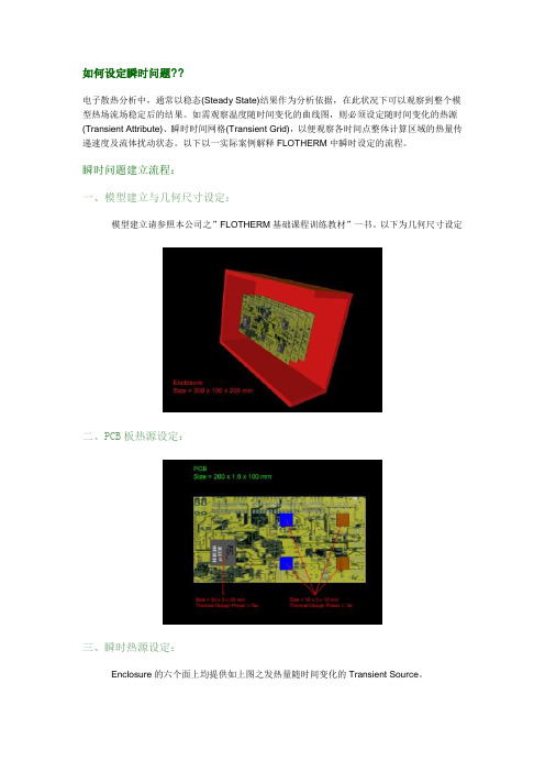
瞬时问题建立流程:一、模型建立与几何尺寸设定:模型建立请参照本公司之”FLOTHERM基础课程训练教材”一书。
以下为几何尺寸设定二、PCB板热源设定:三、瞬时热源设定:Enclosure的六个面上均提供如上图之发热量随时间变化的Transient Source。
四、数值结果显示及说明:由上图结果可以得知,在350秒的时候NC1芯片已超过最大容许温度摄氏125度,所以在350秒的时候此装置已无法正常运作。
五、图形化后处理:问答集Question 1:使用FLOTHERM解决瞬时问题需注意的事项。
Answer:(1) 必须设定材质的密度(Density)及比热(Specific Heat)。
一般求解稳态的案例中,因密度及比热不随时间的变化,所以可以忽略不设定。
(2) 时间网格( Transient Grid )。
FLOTHERM为一自动网格系动热流仿真软件,当设定瞬时热源以后,软件本身会自动设定其时间网格。
所以当求解瞬时问题时,可先设定瞬时热源再设定时间网格。
Question 2:如何设定瞬时热源?!Answer:瞬时热源顾名思义为发热量随时间而改变,FLOTHERM中提供以下几种热源设定。
Question 3:瞬时收敛性的问题。
Answer:瞬时问题收敛性有关于模型本身物理性的网格与时间性网格的设定。
当无法收敛的时候两者都必须作网格收敛性的测试。
详情请参阅Flomerics 网站( /)中的技术文件”Convergence and Transient Simulation”何谓局部加密?? <TOP>局部网格加密理论Validation - 1D ConductionWithout validation of the most basic of cases there is no way trust can be gained in the localized grid solution of more complex models. This model shows that a perfect linear variation in T in this conduction only analysis is predicted both with and without the use of localized grid. It is my belief that if this case was set up and solved in competitive codes that offered such a gridding capability there would be ‘kinks’ in the T profile, kinks that are highly sensitive to the quality of the grid.Validation - 2D Conduction,Getting slightly more complex...Validation - 2D Convection,The first graph indicates that there is a difference. The second graph is for a much finer grid both localized and non-localized. This therefore demonstrates that the difference observed in the first graph was because BOTH localized and non-localized were not grid independent." Don't assume that if localized does not equal non-localized that the localized grid is wrong some how"。


flotherm散热学习(中文教程)flotherm散热学习(中文教程)编辑整理:尊敬的读者朋友们:这里是精品文档编辑中心,本文档内容是由我和我的同事精心编辑整理后发布的,发布之前我们对文中内容进行仔细校对,但是难免会有疏漏的地方,但是任然希望(flotherm散热学习(中文教程))的内容能够给您的工作和学习带来便利。
同时也真诚的希望收到您的建议和反馈,这将是我们进步的源泉,前进的动力。
本文可编辑可修改,如果觉得对您有帮助请收藏以便随时查阅,最后祝您生活愉快业绩进步,以下为flotherm散热学习(中文教程)的全部内容。
FLOTHERM/China/1/06 V6 Issue 1.0练习题 1: FLOTHERM软件的基本操作本练习通过创建一个非常简单的算例让用户对Flotherm软件的操作有一个基本的了解。
本练习逐步指导用户完成安放在钢板的热模块的创建,具体步骤如下1.创建和保存一个新的项目2.创建实体3.定义网格、求解4.分析结果FLOTHERM/China/1/06 V6 Issue 1.0 Page 2练习题 1: FLOTHERM软件的基本操作从[开始/程序/ Flomerics/FLOTHERM 6。
1/FLOTHERM 6。
1]启动FLOTHERM或用桌面快捷键出现彩斑屏幕,接着项目管理窗口(ProjectManager以下简称PM)会自动打开.FLOTHERM/China/1/06 V6 Issue 1.0 Page 3单击项目管理窗口(PM)的顶部菜单条’Project’(项目),下拉菜单,选择‘Save As’(另存为).在顶部的数据框(文本‘Project Name'(项目名称)右边)中键入项目名称“Tutorial 1”,另外在‘Title’(标题)输入框中键入“FirstFlotherm Tutorial"点击按钮‘Notes’(备注),打开输入框让用户输入项目相关注释,如:在下面我们可以用改变的日志区分建模过程,现在,只要点击按钮‘Date’(日期) 把当前的日期加入文本区。
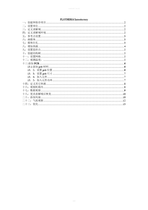
FLOTHERM Introductory一:创建和保存项目 (2)二:设置单位 (2)三:定义求解域 (2)四:定义求解域环境 (2)五:参考点设置 (3)六:画箱体 (3)七:箱体打孔 (3)八:增加热源 (4)九:设置监控点 (5)十:创建结构树 (5)十一:设置网格 (5)十二:观测温度: (5)十三:添加PCB (6)13.1:添加pcb材料 (6)13.2:设置pcb位置 (6)13.3:设置pcb尺寸 (7)13.4:加入元件 (7)13.5:加入元件功率 (7)十四:定义其它热源 (8)十六:观察机箱内 (8)十七:数据观察 (9)十八:更改求解域后恢复 (10)二十:添加风扇 (10)二十二:气流观察 (12)二十三:优化 (13)一:创建和保存项目在PM中选择[Project/New]并选择“Defaults” 表. 选中文件“DefaultSI” 并按OK. 这就按缺省设置(标准国际单位)打开一个新的工程文件,其它的设置参数也都回复为缺省值。
在PM中选择[Project/Save As](项目/保存为)。
—在Project Name (项目名称)栏中键入“Tutorial 2”。
—在Title(标题)栏中键入“Simple Electronics Box”。
—单击Notes(备注)按钮。
在文本编辑框中输入一些和项目有关的信息。
比如“This is an initial model of the electronics box.”。
单击Date(日期)和Time(时间)按钮,为项目创建日期和时间信息。
单击OK按钮,退出Edit Notes(备注编辑)对话框。
再单击确定(OK)来保存您的项目。
二:设置单位整体的缺省尺寸单位可在PM中设置。
在菜单条上, 选择[Option/Units].在‘Unit Class,’ 下面选中‘LENGTH’ 并在‘Use Units’ 中选择‘mm’。
flotherm教程FloTHERM是一款热仿真软件,用于分析电子设备的热管理。
以下是FloTHERM的基本教程。
1. 软件安装:首先,下载并安装FloTHERM软件。
安装完成后,启动软件。
2. 项目设置:在打开的FloTHERM界面中,选择"File"菜单,然后选择"New Project"。
在弹出的对话框中,选择项目保存的位置和名称。
3. 几何建模:在FloTHERM界面左侧的"Geometry View"窗口中,创建设备的几何模型。
可以通过绘制和修改几何形状来精确建模设备。
确保几何模型准确地反映了实际设备的尺寸和形状。
4. 材料属性设置:在右侧的"Model Browser"窗口中,选择需要设置材料属性的几何模型部件。
然后,选择"Modify"菜单,再选择"Thermal Conductivity"或其他属性选项。
设置每个部件的材料属性,如热导率、密度等。
5. 边界条件设置:在"Model Browser"窗口中,选择需要设置边界条件的几何模型部件。
然后,选择"Modify"菜单,再选择"Boundary Conditions"。
根据设备的实际工作环境,设置边界条件,如环境温度、风速等。
6. 网格划分:在"Mesh Control"窗口中,选择网格划分选项,并设置网格密度。
通过调整网格密度,可以控制热仿真的精度和计算速度。
7. 热仿真计算:在FloTHERM界面左下方的"Analysis Control Panel"窗口中,选择"Calculate"按钮,开始进行热仿真计算。
软件将在计算过程中模拟设备的热传导和对流过程,并生成温度分布等结果。
8. 结果分析:在FloTHERM界面右侧的"Results Browser"窗口中,选择要查看的结果文件。
FloTHERM(5.1) Tutorial研发厂商:Flomerics中国代理:海基科技FLOTHERM (5.1)What is FLOTHERM?FLOTHERM is a powerful 3D computational fluid dynamics software that predicts airflow and heat transfer in and around electronic equipment, including the coupled effects of conduction, convection and radiation.FLOTHERM is powerful 3D simulation software for thermal design of electronic components and systems. It enables engineers to create virtual models of electronic equipment, perform thermal analysis and test design modifications quickly and easily in the early stages of the design process well before any physical prototypes are built. FLOTHERM uses advanced CFD (computational fluid dynamics) techniques to predict airflow, temperature and heat transfer in components, boards and complete systems.Unlike other thermal simulation software, FLOTHERM is a Design-Class or industry-specific analysis tool specially designed for a wide range of electronic applications that include:∙computers and data processing,∙telecommunications equipment and network systems∙semiconductor devices, ICs and components∙aerospace and defense systems∙automotive and transportation systems∙consumer electronicsAs a Design-Class tool, FLOTHERM features specialization, built-in intelligence and automation not found in traditional analysis software. This functionality maximizes productivity for thermal design experts, minimizes the learning curve for mechanical design engineers and provides the highest levels of return on investment available from analysis software.In a small to medium-sized company, FLOTHERM can pay for itself several times over in just one year and even faster as the size of the company increases. Experience the benefits of using FLOTHERM for thermal design of electronics, that include:∙solving thermal problems before hardware is built∙reducing design re-spins and product unit costs∙improving reliability and overall engineering designHow to Run FLOTHERM?FLOTHERM is normally run interactively, so problem setup, flow calculation and results analysis can be completed in the same program session.To Start an Interactive SessionOn NT/Windows 2000/XP PlatformsIn the Flotherm51 group use the following menu sequence:Start -> Programs -> Flomerics -> FLOTHERM -> FLOTHERM 5.1Exiting FLOTHERM :To exit from FLOTHERM, in the Project Manager choose Exit from the Project menu.FLOTHERM then checks for project changes before exiting the program.If changes are detected, you are given the chance to save them using a query dialog. There are three options:a. [Yes] saves the project and solution data before exiting.If saving a new project, the Save Project Dialog, appears so you can give it a name, title and class.An existing project is overwritten.b. [No] does not save the project before exiting.c. [Cancel] cancels the exit request.Getting Started :-1. Creating a New Project:-∙Create a new project using the DefaultSI template.∙Name the New Project :Choose Save As... from the Project menu.Name = BasicsTitle = Fundamentals of FLOTHERM∙Add Reminders :Click on [Notes] to call the notepad editor dialog. Using the Edit Notes dialog you can add notes to accompany the project. For example a change log could be included to identify the modeling process followed.For the purposes of this exercise just type "Learning the fundamentals of FLOTHERM" and append the date to the text by clicking on [Date] and click [OK] in the Edit Notes dialog.2. How to Set the Size of the Solution Domain :-∙Display the System Menu:Move the mouse over the System node and right-click to display the System menu.∙Open the Overall Solution Domain dialog:Choose Location... from the System menu.∙Set Size of Solution Domain:Leave the Position settings at zero, but define the Size as:X=0.07m, Y=0.40m, Z=0.30m.3. Creating a Large Plate :-∙Create the GeometryRepresent a large plate in the project by adding a cuboid made of mild steel.∙Open the New Object Palette∙Click on the Root Assembly to select it and click the palette icon at the top of the Project Manager to open the New Object∙Call the Edit Primitive Dialog to change the Cuboid Defaults :Right-click the new cuboid and choose Location... from the pop-up menu to call the Edit Primitive Dialog.∙Define the Large Plate :In the Edit Primitive dialog, changeName to Large Plateand set position to:X=0.03 m, Y=0.10 m and Z=0.10 mand set size to:X=0.005 m, Y=0.1 m 0, Z=0.15 mClick [Apply] to confirm the settings.Note that the numbers entered are converted to scientific notation, however, they can be entered in any format. Click [OK] to dismiss the dialog and the cuboid can be seen renamed in the tree.∙Attach a Material using the Library :Open the Library Manager Open the Library Manager by either clicking again on the palette button, or the Library Manager button∙Access the Alloy Materials:∙Attach Attribute:Left click-drag Steel (Mild) onto the Large Plate.4. How to Create a Heated Block : Add a cuboid with an attached Alumina ceramic property to represent a heated block.∙Create the Geometry.∙Add a Cuboid. Select the Root Assembly and add another cuboid.∙Open Edit Primitive dialog. Right-click the new cuboid and choose Location...from the pop-up menu.∙Change the Cuboid Definition.Make the following settings in the Edit Primitive dialog:Rename the object to Heated BlockSet Position to: X=0.035 m, Y=0.12 m, Z=0.14 m Set Size to: X=0.005 m, Y=0.04 m, Z=0.04 m and click [OK].∙Attach a Property using the Library.∙Attach a Material Property to the Heated BlockExpand the Libraries node down to: Libraries->Flomerics_Libraries->Materials->CeramicsLeft click-drag Alumina (Typical) onto the Heated Block.∙∙Close the Library Manager:∙Close the library by clicking on the double arrow, the palette icon or the F7 function key.∙Attach a Thermal Attribute using the Dialogs:Because the thermal attribute now required is not in the library, now create a new attribute.∙Call the Thermal Selection Dialog:Right-click the Heated Block cuboidand choose Thermal from the pop-up menuto call the Thermal selection dialog.∙Create a New Thermal Attribute:Click [New...] in the Thermal Dialog to displaythe Thermal Attribute.Now make the following settings:Name = Block HeatThermal Model kept as ConductionTotal Power = 8 WClick [OK] to return to the Thermal selection dialog.∙Attach the New Thermal:With Block Heat highlighted in the Thermal list, click on [Attach].Note that the Currently Attached field updates when the attribute is successfully attached.[Dismiss] the dialog.∙Save the Project:Choose Save from the Project menu or click the save button.Note: During model set up it is a very good idea to save the project at regular intervals.5. How to Set the Grid :-The Drawing Board can be used to view the grid as well as the geometry structure.∙Display the Drawing BoardClick the button in the Project Manager to launch the Drawing Board.In the Drawing Board we can see the two blocks we have just created in 2D or 3D views. ∙Display the GridPress g on the keyboard to display the grid.Note that, at present, the grid is created by the geometry boundaries alone (i.e. the key point grid). This will not be sufficient to achieve a solution, so more grid must be added.∙Adding Grid:∙Display the System Grid DialogThere are a number of methods available, but here we will use a pre-set system grid. In the Drawing Board, choose System Grid... from the Grid menu to display the System Grid dialog.∙Add a Fine GridIn the System Grid dialog activate the Dynamic Update and click on [Fine]. The grid display in the Drawing Board updates.The program defines positions for the minimum and maximum cell sizes using a smoothing algorithm. 6. Solving the Project :-∙The solver requires less than 35 iterations for the solution to converge.∙Start the Solution∙Click in either the Drawing Board or Project Manager to start the solution. A sanity check is performed first and the message window appears indicating an open external boundary does not have an ambient attached.For now, ignore this since the default ambient (set in the Global System Settings dialog) will besufficient for our purposes.∙After the sanity check has been performed, the solution continues and the Profiles window opens and the progress bar displayed.∙The solution completes to show a converged plot.7. Visualizing the Results :-FLOMOTION can be used to display plots of results superimposed over the model.∙Display FLOMOTIONClick to launch FLOMOTION.A 2D view of the geometry is shown.∙Change to a 3D View: Press "i" in the keyboard to change to a 3D isometric view.∙Add a Plane PlotIn the Plane Plot Panel, change the direction to Z.and click the Create Plane button∙ A temperature contour fill plot is displayed.∙Change Geometry to Wireframe∙Press "w" in the keyboard to make thegeometry wireframe.∙The geometry becomes transparent allowingthe hidden results to be seen. Warning: under some conditions, theresults will also b ecome wireframe, so you can’t see them.8. Tabulating the Results :-In addition to viewing a graphical representation of the results, we can look at tabulations of data using the Tables window. For example, we can investigate the amount of heat conducted from the heated block, or, the amount of heat convected from the surface of the heated block to the air.∙Display the Tables Window: Click to launch the Tables window.The default view shows a summary of the geometry set up.∙Choose Data for Solid ConductorsClick to display the Geometry Table Selections dialog.Check Solid Conductors and click [OK].∙Display Summary Results∙Click to page down to display the summary table forsolid conductors. As you scroll across the surfacetemperature, conducted heat and convected heatare displayed for each surface of the conductingcuboids.Extra Points: Here we won’t be providing as much detail, so you’ll need to do some investigating on your own.1. Now add a monitoring point to the heated block so we can determine its temperature.∙Display the Project manager window.∙Highlight the Root Assembly and click on the icon at the right side of the Project Manager to add the Monitoring Point.∙Call the Edit Monitor Point to change the Monitor Point Position:Right click the Monitoring Point and choose Location…from the pop-up menu to call the Edit Monitor Point.∙Positioning the Monitoring Point:In the Edit Monitor Point, change the Name and Location to the desired one by allocating (x,y,z) co-ordinates. Choose coordinates to place the monitoring point in the center of the heated block.2. Now add a heat sink to your heated block.∙Display the Project manager window.∙Highlight the Root Assembly and click on the icon at the right side of the Project Manager to add a Heat Sink.∙Call the Edit Smart Part to change the Heat Sink Position:Right click the Heat Sink and choose Location…from the pop-up menu to call the Edit Smart Part.∙Positioning the Heat Sink:In the Edit Smart Part, change the Name and Location to place your heat sink on top of the heated block. Check to make sure that the heat sink has been placed in the proper location. You may need to experiment a bit. You will see that the heat sink is placed in the x-y dimension with the find extending in the z dimension, which isn’t what we want. Go to Tools-Rotate Clockwise to rotate the heat sink to the proper orientation. You will also need to pick a material and geometry for your heat sink. Aluminum is the most common material. Choose whatever geometry you’d like (pin fins or channels, heat sink height, etc.)3. Now add an enclosure, and cut holes in it for a fan and for an exhaust vent.∙Display the Project manager window.∙Highlight the Root Assembly and click on the icon at the right side of the Project Manager to setup an Enclosure. Make an enclosure large enough to enclose your whole system, with some room left over.∙You can see that the Enclosure has six walls, so we can introduce a hole wherever desired.∙Choose a location for your fan and for the exhaust vent. Click on the wall where a hole is to beadded and select the icon.∙In order to position the hole, we allocate the co-ordinates as desired.∙Call the Edit Smart Part to change the Hole’s position:Right click the Hole and choose Location…from the pop-up menu to call the Edit Smart Part.∙Positioning the Hole: In the Edit Smart Part, change the Name and Location to the desired one by allocating (x,y,z) co-ordinates. Pick any reasonable size for the wholes for your vent and fan.4. Now add a fan.∙Display the Project manager window. Highlight the Root Assembly and click on the icon at the right side of the Project Manager to add a Fan.∙Call the Edit Smart Part to change the Fan’s Position:Right click the Fan and choose Location…from the pop-up menu to call the Edit Smart Part.∙Positioning the Fan:In the Edit Smart Part, change the Name and Location to the desired one by allocating (x,y,z) co-ordinates.∙Go back to the fan menu to change the construction of the fan. Check out the various options available. For example, you can set a fixed flow rate, or you can even enter your own fan curve. For this exercise, choose any reasonable fixed flow rate.5. Now re-solve the project.∙Start the Solution∙Click in either the Drawing Board or Project Manager to start the solution. A sanity check is performed, after the sanity check has been performed, the solution continues and the Profiles window opens and the progress bar is displayed.∙Spend some time investigating to solution in FLOMOTIONThis ends the Flotherm Tutorial. If you have extra time available, spend some time investigating other aspects of the program or add some new element to your project. It will take quite a bit of time before it becomes easy for you to use this (or any other CFD) program!Possible Solution Scenarios:When the solution process is initiated, the most likely scenario is that the solution will converge, but there are the following possibilities reflected by the residual error plots shown below.Controlling the SolutionIf your solution fails to converge or converges extremely slowly, then you can reset the solution control panels, but first consider the following rules for assessing a solution convergence problem as the problem may well lie in the project set-up.Rules for Assessing Convergence Problems1. If a solution diverges, it is almost guaranteed to be a problem definition problem. Be immediatelysuspicious of the set up and check all defined objects and attributes before proceeding to alter any solution control parameters.2. If a solution fails to converge successfully, then it is important to check the grid. If there are pooraspect ratio grid cells and large jumps in grid size between adjacent grid cells, then this is the likely cause of the problem.3. If you are happy with the set up and the grid, then and only then should the solution controlparameters be adjusted.4. Do not waste time forcing low-level stable or low-level oscillation convergence profiles downto a residual error level of 1. Use the monitor points and error field to sensibly assess whether the solution is converged to a defined level of accuracy, and then stop the solution.If you do need to change the control parameters, then the following section provides an overview of how to resolve and manage the solution process.Techniques for Controlling the SolutionFLOTHERM contains a number of techniques, both automatic and manual, which can be used to optimize the solution process. In discussing their use, it is important to note that it is only possible to give general guidelines rather than hard and fast rules on how they should be altered for particular situations.In FLOTHERM, extremely complex and highly non-linear systems involving multiple modes of heat transfer are being modeled and it is impossible to automatically generate appropriate solution control parameters that will guarantee convergence under all circumstances. The automatic settings have been designed to give a reasonable convergence profile for the majority of applications, but may need to be adjusted in more complex situations.Much of this tutorial has been copied directly from the online Flotherm manual. It has been put together in this form by Girish Suppa with additions/modifications by Nicole Okamoto.。