ST400操作使用说明书
- 格式:pdf
- 大小:8.07 MB
- 文档页数:22
SPECIFICATIONSilverStone STRIDER ST400ATX12V 2.2 Switching Power SupplyPS/2 400W1. GENERAL REQUIREMENTSThis specification describes a 400 watts power supply. With+ 5V stand-by , remoteON/OFF control for ATX system and passive PFC(Power Factor Correction) (option)circuit at 230 Vac.2. INPUT REQUIREMENTSThe power supply shall operate in 115Vrms±10% or 230Vrms ±10%. The powersupply shall operate from an AC mains frequency of 47 through 63 Hz. Maximuminrush current from power-on (with power on at any point on the AC sine) andincluding, but not limited to, three line cycles, shall be limited to a level below thesurge rating of the input line cord, AC switch if present, bridge rectifier, fuse, and EMIfilter components. Repetitive ON/OFF cycling of the AC input voltage should notdamage the power supply or cause the input fuse to blow.The AC mains steady-state RMS input current shall be:8.5 amps maximum / 115 Vrms, 60 Hz.5 amps maximum / 230 Vrms, 50 Hz.01STRIDER ST4003. OUTPUT REQUIREMENTS3.1 OUTPUT VOLTAGE AND CURRENT(1) +3.3V &+5V total output not exceed 180W.When +3.3V is load to 28A,the +5V maximum load is 17.52A.When +3.3V is load to 9.0A,the +5V maximum load is 30A.(2) +12V1DC & +12V2DC total output not exceed 348W.(3) +3.3V &+5V & +12V1DC & +12V2DC total output not exceed 385W.(4) All outputs shall be safety-isolated from the AC mains and share a common return.This common return must be connected to supply chassis.(5) Voltages and ripple are measured at the load side of mating connectors with a 0.1 uFmonolithic ceramic capacitor paralleled by a 10 uF electrolytic capacitor across themeasuring terminals.02LOAD REGULATION CHARACTERISTICS3.2 REMOTE ON/OFF CONTROLThe power supply shall accept a logic open collector level which will disable / enableall the output voltage (exclude + 5V standby ).As logic level is low, outputs voltage were enable.As logic level is high, outputs voltage were disable.Note:1. Logic high level :3.50-5.25V while sourcing 0.4mA maximum.2. Logic low level : 0-0.5V while sinking 1.5mA maximum.3. Rise Time : 2ms maximum (10%-90%).3.3 OUTPUT VOLTAGE HOLD-UP TIME17.0 mS minimum : at 115V / 60 Hz. (COND.6)17.0 mS minimum : at 230V / 50 Hz. (COND.6)3.4 OPERATION AT NO LOADThe power supply shall be capable of being operated with no load on any or alloutputs without damage. For no load on +3.3V&+5V, the output shall not exceed+4.5 & +6.5Vdc and the power supply may shutdown and require by remote-controlor remove AC power restart.03STRIDER ST4003.5 PROTECTION3.5.1 Over-voltage protectionIn the event of an over-voltage condition on +3.3 & +5Vdc &+12V the power supplyshallshutdown and require remote control or remove the AC mains input to reset the system.+5V : 6.5V (maximum)+3.3V : 4.6V (maximum)+12V1DC : 15.5V (maximum)+12V2DC : 15.5V (maximum)3.5.2 Over-LOAD protectionThere shall be protection from an output over-current event. The supply may shutdown form such an event and require power-on restart. Testing consists of application of the listed over-current value with maximum load on all other outputs.Over-current test values: (maximum load)+3.3V : 90A maximum+5V : 68A maximum+12V1DC : 32A maximum+12V2DC : 32A maximum3.5.3 Short-Current ProtectionA short circuit at any output shall cause no damage to the power supply nor blow the primary fuse. The supply may shut down in the event of a short circuit and requirepower-on restart. A short circuit consists of application of a test resistance of lessthan 0.05 ohms at each output with maximum load on all outputs.3.6 OUTPUT RISETIMEThe cold-start enable output voltage risetime of all outputs shall be measured with maximum load on all outputs.risetime : +3.3V 20mS (maximum)(10-95%) +5V 20mS (maximum)+12 V1DC 20mS (maximum)+12 V2DC 20mS (maximum)-12 V 20mS (maximum)+5Vsb 20mS (maximum)04053.10 POWER ON TIME115/230V (FULL LOAD) : 500mS minimum.Figure 1T2 : RISETIME < 20mST3 : POWER GOOD DELAY TIME 100mS-500mS T4 : POWER GOOD RISETIME ɷ10mS3.7 OUTPUT OVERSHOOTNo output voltage shall overshoot or generate spikes at turn-on or turn-off, during momentary power loss, output short, or realistic input voltage or output load changes, Overshoot is defined as any output that exceeds the voltage tolerance plus or minus an additional 5%.3.8 EFFICIENCYOverall efficiency must be 70% minimum measured at normal AC mains voltage and frequency with maximum loads on all outputs.3.9 POWER GOOD SIGNAL115/230V (FULL LOAD) : 100-500mSSTRIDER ST400 4. PHYSICAL ENVIRONMENT4.1 OPERATING CONDITIONSThe power supply shall be capable of continuous operation and meet all electricalspecification without need for adjustment when subjected to the followingenvironmental conditions:4.1.1 AMBIENT TEMPERATURE : 0 TO 50ʨThe maximum continuous power rating of supply is 400W at 25ʨ. De-rate 2W / ʨfrom 25ʨ to 50ʨ.4.1.2 RELATIVE HUMIDITY : 90%4.2 STORAGE AND SHIPPING CONDITIONSNo degradation of the power supply shall occur during shipping or storage at thespecified conditions.4.2.1 AMBIENT TEMPERATURE : -20 TO +65ʨ4.2.2 RELATIVE HUMIDITY : 95%4.3 SHOCK AND VIBRATIONThe power supply will withstand the following imposed conditions without experiencing non-recoverable failure or deviation form specified output characteristics. Storage -40G, 11mSec. half-sine wave pulse in both directions on three mutually perpendicular axes.Operating -10G, 11mSec. half-sine wave pulse in both directions on three mutuallyperpendicular axes.Vibration Operation-Sine wave excited, 0.25G maximum acceleration.10-250 Hz, swept at one octave/min. Fifteen minute dwell at all resonant points, where resonance is defined as those exciting frequencies at which the device under testexperiences excursions two times large than non-resonant excursions.065. REGULATORY COMPLIANCE5.1 SAFETY REQUIREMENTS-TUV EN60950-UL 609505.2 DIELECTRIC STRENGTHPrimary to Frame Ground : 1800 Vac for 1 sec.Primary to Secondary : 1800 Vac for 1 sec.5.3 INSULATION RESISTANCEPrimary to Secondary : 20 Meg. ohms Minimum.Primary to FRAME GROUND : 20 Meg. ohms Minimum.5.4 GROUND LEAKAGE CURRENTThe power supply ground leakage current shall be less than 3.5mA.5.5 EMISSION REQUIREMENTSWhen testing the power supply must operate within the listed requirements.6 OTHER REQUIREMENTS6.1 COOLINGWith the fan voltage set to around 12 volts, the fan will deliver greater than 38.2 CFM with the power supply in open air.6.2 INPUT CONNECTIONSRefer to Mechanical Specifications for placement. The AC mains input are through athree-circuit IEC type connector mounted on the rear of the power supply chassis.07STRIDER ST4006.3 RELIABILITYThe power supply reliability, when calculated by MIL-HDBK-217; latest revision, areexceed 100,000 hours with all output at maximum load and an ambient temperature of 25ʨ.6.4 PIN DEFINITIONM/B 24PIN connectorATX 12V 4PIN connector6PIN PCI Express Connector0809Fan voltage varies with the ambient temperature or output power.7. FAN SPEED CONTROLSATA connector4PIN peripheral connector (HDD) 4PIN floppy connector (FDD)8. Power Supply Dimension : 150mm(W) 86mm(H) 140mm(D)STRIDER ST400 20885 Currier RoadCity of Industry , CA 91789Tel: 909-598-2318Fax: 909-598-2518usasales10。
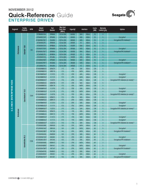
New Seagate Model Number Key, EnterpriseST 500 NM 123 1BRANDCAPACITYSEGMENTATTRIBUTESGENERATION2 letters ST = Seagate MX = Maxtor2 to 4 digits 500 = 500GB 1000 = 1000GBCapacities >9999GB:10 = 10TB 15 = 15TB2 lettersMM = Mission-Critical, 2.5-Inch, 10K MX = Mission-Critical, 2.5-Inch, 15K NM = Nearline, 3.5-Inch NX = Nearline, 2.5-Inch FM = SSD Mainstream FX = SSD Performance3 digits, non-intelligentVaries as needed, for example:Interface RPM Cache SED1 digit, intelligent 1 = 1st Generation2 = 2nd Generation3 = 3rd GenerationSeagate Partner Program MembersVisit the Sales Tools section to access the latest product roadmap, end-of-life schedule and product information. DistributorsEMEA SPP Support00-800-6890-8282US Sales Support1-800-SEAGATE or 1-405-324-4700Visit for more information or call 1-800-SEAGATE (1-800-732-4283) © 2012 Seagate Technology LLC. All rights reserved. Printed in USA. Seagate, Seagate Technology and the Wave logo are registered trademarksof Seagate Technology LLC in the United States and/or other countries. Cheetah, Constellation.2, Pulsar, Pulsar.2 and Savvio are either trademarks or registered trademarks of Seagate Technology LLC or one of its affiliated companies in the United States and/or other countries. The FIPS logo is a certification mark of NIST, which does not imply product endorsement by NIST, the U.S., or Canadian governments. All other trademarks or registered trademarks are the property of their respective owners. When referring to drive capacity, one gigabyte, or GB, equals one billion bytes and one terabyte, or TB, equals one trillion bytes. Your computer’s operating system may use a different standard of measurement and report a lower capacity. In addition, some of the listed capacity is used for1 One gigabyte, or GB, equals one billion bytes and one terabyte, or TB, equals one trillion bytes when referring to hard drive capacity.2 Self-Encrypting Drives (SED) and FIPS 140-2 Validated drives are not available in all models or countries. May require TCG-compliant host or controller support.3 See FIPS 140-2 Level 2 Certificate at /groups/STM/cmvp/documents/140-1/1401val2010.htm#12994 Data provided is based on format at 512 bytes.View a brief training presentation on how our model number format has changed at /seagate/ModelNumber。
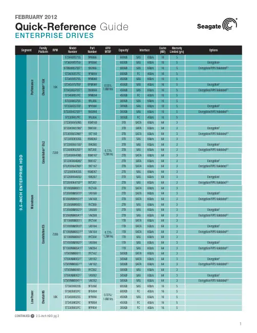
CONTINUED > 2.5-Inch HDD pg 2CONTINUED > 2.5-Inch SSD pg 3New Seagate Model Number Key, EnterpriseST 500 NM 123 1BRANDCAPACITYSEGMENTATTRIBUTESGENERATION2 letters ST = Seagate MX = Maxtor2 to 4 digits 500 = 500GB 1000 = 1000GBCapacities >9999GB:10 = 10TB 15 = 15TB2 lettersMM = Mission-Critical, 2.5-Inch, 10K MX = Mission-Critical, 2.5-Inch, 15K NM = Nearline, 3.5-Inch NX = Nearline, 2.5-Inch FM = SSD Mainstream FX = SSD Performance3 digits, non-intelligentVaries as needed, for example:Interface RPM Cache SED1 digit, intelligent 1 = 1st Generation2 = 2nd Generation3 = 3rd GenerationSeagate Partner Program MembersVisit the Sales Tools section to access the latest product roadmap, end-of-life schedule and product information. DistributorsEMEA SPP Support00-800-6890-8282US Sales Support1-800-SEAGATE or 1-405-324-4700Visit for more information or call 1-800-SEAGATE (1-800-732-4283) © 2012 Seagate Technology LLC. All rights reserved. Printed in USA. Seagate, Seagate Technology and the Wave logo are registered trademarksof Seagate Technology LLC in the United States and/or other countries. Cheetah, Constellation.2, Pulsar, Pulsar.2 and Savvio are either trademarks or registered trademarks of Seagate Technology LLC or one of its affiliated companies in the United States and/or other countries. The FIPS logo is a certification mark of NIST, which does not imply product endorsement by NIST, the U.S., or Canadian governments. All other trademarks or registered trademarks are the property of their respective owners. When referring to drive capacity, one gigabyte, or GB, equals one billion bytes and one terabyte, or TB, equals one trillion bytes. Your computer’s operating system may use a different standard of measurement and report a lower capacity. In addition, some of the listed capacity is used for formatting and other functions, and thus will not be available for data storage. Actual data rates may vary depending on operating environment and other factors. The export or re-export of hardware or software containing encryption may be regulated by the U.S. Department of Commerce, Bureau of Industry and Security (for more information, visit ). Seagate reserves the right to change, without notice, product offerings or specifications. QR501.14-1202US, February 20122 Self-Encrypting Drives (SED) and FIPS 140-2 Validated drives are not available in all models or countries. May require TCG-compliant host or controller support.3 See FIPS 140-2 Level 2 Certificate at /groups/STM/cmvp/documents/140-1/1401val2010.htm#12994 Data provided is based on format at 512 bytes.View a brief training presentation on how our model number format has changed at /seagate/ModelNumber。
SCL-400型皮带秤显示仪表使用说明书北京市煤炭矿用机电设备技术开发公司北京斯凯尔工业自动化研究所序章功能及特征 (3)第一章各部名称及其功能 (4)序章功能及特征 (3)第一章各部名称及其功能 (4)1.1 前面板 (5)1.1.1显示屏 (5)1.1.2 状态指示灯 (6)1.1.3 按键 (6)第二章操作指南 (7)2.1 仪表上电自检 (7)2.2 显示切换 (7)2.3 参数设臵 (8)2.4 操作选择 (13)第三章电子皮带秤标定 (14)3.4 零点标定 (18)3.5 速度标定 (18)3.6 计量标定 (19)3.6.1 实物标定 (19)3.6.2 模拟标定 (20)3.6.3 模拟校验 (22)3.7影响标定误差的因素 (22)第四章包装、运输、贮存 (22)4.1产品包装符合铁路或汽运要求,包装箱外壳标明如下内容: (22)4.2 随同产品文件: (22)4.3 运输 (22)4.4 贮存 (22)第五章质量保证 (22)附录1 电子皮带秤基础知识23序章功能及特征作为皮带秤和皮带定量给料机的积算调节仪表SCL-400,是对皮带输送系统中的散状物料进行连续计量的理想设备,具有结构简单、称量准确,使用稳定、操作方便、维护量少等优点。
主要应用于冶金、电力、煤炭、矿山、港口、化工、建材等行业。
图1 SCL-400型电子秤仪表计量监控系统结构示意图特点:1)可靠性高采用了新型材料的非易失性存储器,保证了累计量、运行状态、各种参数值、设定值等重要数据可以存储长达100年,断电后不会丢失数据。
设计时,通过增加滤波器、模拟电路和逻辑电路通过光电耦合器完全隔离以及PCB布局时将高频区域、功率区域、数字区、模拟区分别处理等手段,提高了仪表的抗干扰能力,能通过4000V脉冲干扰测试。
2)具备多种通讯接口在仪表的主板上设计了通用型的通讯接口,可兼容我公司生产的点对点式及总线式调制解调器通讯板、485总线通讯板、CAN总线通讯板、以太网通讯板和无线射频通讯板。
ST型光电保护装置使用说明书济宁莱恩光电科技有限公司JINING LAIEN OPTIC-ELECTRIC TECHNOLOGY CO.,LTD.序 言感谢您选用ST型光电保护装置!ST型光电保护装置主要用于锻压行业,与冲压设备配套保护操作者人身安全。
本装置仅保护传感器与反射器(或发光器与受光器)之间的矩形光幕区域。
如果其安装位置不正确,或不按说明书与相关安全作业条例操作或机床执行机构故障,都可能使其无法起到保护作用。
因此,安装本装置之前,请仔细阅读说明书,充分理解有关事项,尤其是说明书中标出的“警告”“注意”等内容;在使用过程中,请正确理解光电保护装置的工作性能,严格按照本说明书所提出的要求,制定相应的安全作业条例。
本说明书仅介绍光电保护装置在压力机上的应用,其它用途的光电保护装置,可参照本说明书。
本说明书内容解释权归济宁莱恩光电科技有限公司,阅读或使用本说明书时,如有不明之处,请与本公司联系。
目 录◆基本介绍一. 用途 (1)二. 特点 (1)三. 组成 (2)四. 分类 (5)五. 规格 (6)六. 技术参数 (8)◆安装一. 安全距离的计算及安装位置的确定 (9)二. 安装工具 (11)三. 控制器的安装 (11)四. 传感器、反射器(发光器、受光器)的安装 (12)五. 区域保护用光电保护装置的安装 (17)◆接线一. 外置式控制器(W型)的接线 (18)二. 内置式控制器(N型)的接线 (20)◆调试一. 光电保护装置的调试 (22)二. 回程不保护角度的调整 (22)三. 试运行 (24)◆使用、检查与保养一. 注意事项 (25)二. 检查与保养 (26)◆简单故障检修一. 光电保护装置故障与机床故障判别 (27)二. 控制器故障及检修 (28)三. 传感器(发光器、受光器)故障及检修 (28)基本介绍一、 用途1. 对于滑块能在行程的任意位置制动停止的压力机,可实现全程保护,或与凸轮开关配合,实现30°~180°之间行程的保护。
高速分散机使用说明书上海尚普仪器设备有限公司Shanghai Shangpu Instrument Equipment Co.,Ltd.前言 (1)一、概述 (2)二、结构 (2)三、特点 (4)四、技术参数 (4)五、设备安装 (6)六、设备使用 (6)七、维护保养 (8)八、故障分析 (8)九、保修声明 (9)十、开箱检查 (9)十一、装箱清单 (9)感谢您选择尚仪臭氧发生器,为获得更好的使用体验,请认真阅读本使用说明书,并遵守安全操作规范!请妥善保管本使用说明书以便需要时查阅!注意事项:请确保只有受过相关训练的人员才能操作使用本仪器。
请遵守安全规范、人身安全和事故防止等相关规范。
注意-磁场!使用时需注意磁场对周边环境的影响,尤其是数据存储器、心脏起搏器。
请使用独立的电源插座。
请将仪器电源插头完全地插入电源插座中,请不要使用指定以外的电源。
切勿用湿手去插拔电源插头,亦切勿湿手操作仪器。
不可损毁、修改、拉拽、过度弯曲或扭曲电源线,亦切勿把重物置于电源线上。
请将仪器放置于平稳、坚固、清洁、防滑、干燥和防火的台面上。
不得将设备放置在靠近热源的地方。
每次使用前请注意检查仪器和配件确保无损。
转速大于4000rpm/min时不宜空转。
出现介质飞溅、运转不平稳、仪器发生移动等状况,请降低转速。
禁止长发者及其他可能发生缠绕的物品靠近运行的机器。
如果您在使用过程中,发现仪器有异味或有异常噪音时,应立即切断电源,然后在第一时间联系我司售后服务部。
本仪器电机为串激电机,转动时电刷有火花产生,如发生严重火花,必须立即停机检查,予以修理,以免造成更大损失。
防爆车间不宜使用。
(SN-FS数显高速分散机系列)如果一段时间内不使用仪器,应将电源线插头断开电源。
本仪器仅适用于对处理过程中产生的能量不发生危险反应的介质。
处理有毒、易挥发介质时,请采取适当的防护措施。
不得随意拆卸和调整仪器的零部件,备件损坏时,请仅使用原装备件进行更换。
培训教材一、DCS系统间介1、本系统的上位机软件采用了德国西门子(siemens)公司最新的工控组态软件wincc;下位控制站采用了ST-400 CPU和最新分布式模块ET200M系列自动化才品;现场连接采用工业以太网、profibus现场总线和4-20mA仪号工业标准。
系统拓扑结构见下图2、该系统具有整体集成化、更可靠性、技术先进、扩展性好、价格合理、操作简便。
3、测控围:生料磨、烧成窑尾、烧成窑头、水泥磨该系统由中央控制室的操作站、中央控制站、现场电场控制室的现场控制站以及工业通讯网络等几部分组成。
系统操作站与服务器通过ETHERNET相连,服务器与控制站通过工业以太网连接、控制站通过profibus-dp过程现场总线与现场控制站相连接。
二、主要测控容系统分为四个DCS控制站:每个站又细分为若干工艺段生料控制站分为:石灰石破碎及预均化、生料配料、生料磨;窑尾控制站分为:生料如窑、窑尾预分解、废气处理;窑头控制站分为:窑中和窑头喷、粉制备、蓖冷机;水泥磨控制站为:水泥配料、水泥磨、包装。
三、主要功能特点过程现场级的通讯网络:12Mbit/s标准的I/O测控信号接口:数字输入信号(DI)接口为220VACDO接口:无原继电器触点(5A)AI、AO信号接口:4-20MA操作控制级的通讯网络:开放的ETHERNET工业以太网100M/s中央控制站控制软件开发平台:STEP7软件开发平台(PLC)操作站监控软件的开发平台:WINCC组态软件开发平台(人机界面)功能:实时生产过程监视功能:总貌图、工艺段流程图设备开关机控制功能:开关机及连锁故障报警及管理功能实时皱势及历史皱势图生产报表统计和生产管理功能:班报表、日报表、年报表自动故障检测三个操作级别:底→操作员→管理员→维护员四、系统配置1、硬件:S7-400控制站:1个CPU、1个电源模块、1个以太网通讯模块(网卡)、若干个ET200子站)S7-00中央控制器是自控的控制中心它通过工业以太网与服务器相连又通过PROFIBUS-DP现场总线与各个现场控制站ET200分布式I/O相连。
ST400便携式pH计ST400M便携式多参数测试仪使用说明书目录1简介 (1)1.1安全防护措施 (1)1.2显示与按键 (2)2安装 (5)2.1配置与选配件 (5)2.2仪表充电 (6)3仪表操作 (7)3.1设置 (8)3.1.1系统设置 (8)3.1.2pH设置 (9)3.1.3电导设置* (10)3.1.4电极管理 (10)3.1.5数据管理 (11)3.1.6恢复出厂设置 (11)3.1.7用户向导 (11)3.2P H校准 (12)3.2.1 校准缓冲液组 (12)3.2.2pH单点校准 (13)3.2.3pH多点校准 (13)3.3P H测量 (14)3.3.1 pH测量 (14)3.3.2mV测量 (14)3.3.3温度测量 (14)3.4电导校准 (15)3.4.1设置标准液 (15)3.4.2电导校准 (15)3.5电导测量 (16)3.5.1 电导测量 (16)3.5.2TDS、盐度与电阻率测量 (16)3.6双参数测量 (16)4数据存储 (17)4.1存储读数 (17)4.2浏览存储数据 (17)4.3删除存储数据 (17)4.4导出存储数据 (17)5维护 (18)5.1出错信息 (18)5.2仪表维护 (19)5.3电极维护 (20)6技术参数 (21)附录 (25)表1缓冲液组随温度的变化 (25)表2温度补偿系数实例(Α值) (28)表3电导标准溶液 (28)CN-1 ST400 & ST400M 1简介感谢您选择了奥豪斯公司的高品质产品。
在您使用前,请仔细阅读本说明书,将对使用及维护本仪器有很大的帮助。
STARTER系列电化学产品的STARTER400系列便携表是针对野外或现场测量而设计的防水仪表。
其中ST400是一款0.01pH精度的便携式pH计。
ST400M是一款集0.01pH精度的pH计和0.5级精度的便携式电导率仪为一体的双参数便携仪表。
以上两款仪表皆可广泛应用于工业企业、环保监测等。
1.电焊机 ZXE1-500 说明书品牌:TAYOR上海通用电焊机型号:ZXE1-500 工作形式:弧焊焊接方式:手工焊电流:交流样式:手持式驱动形式:无保护气体类型:无作用对象:金属额定容量:43KVA 负载持续率:35% 适用对象:建筑行业工作电压:单相380V 电流调节范围:120-500A 重量:124KG尺寸:460×865可焊焊条直径:2.5-6.0mm2.电焊机ZX7-400ST/400STG 说明书品牌:奥太山大奥太伯乐型号:ZX7-400STG ZX7-400S ZX7-400STZX7-500STG ZX7-315S工作形式:逆变焊焊接方式:弧焊电流:直流样式:手持式驱动形式:电动保护气体类型:二氧化碳作用对象:金属额定容量:18.4KVA 负载持续率:60%适用对象:碳钢不锈钢工作电压:380V 电流调节范围:20-400A 操作方式:手动加工定制:否系列焊机:ZX7-315\400\500\630 功能:手弧焊、氩弧焊【性能特点】■控制面板优良设计●数字显示,焊接电流可调精度1A ● 引弧电流可以单独调节,具有优异的引弧性能●推力电流可任意调节● 氩弧焊有自锁/非自锁功能,具有高频和接触两种引弧方式■具有多种安全防护功能● 温度保护、过流保护、短路保护等●焊机内关键部件采用“三防”设计焊接方式:手弧焊焊接方式:手弧焊焊接方式:氩弧焊焊接位置:平焊焊接位置:环缝焊接位置:平焊焊材:碳钢12mm 焊材:碳钢12mm 焊材:不锈钢6mmφ2.4(钨极) φ5焊条φ3.2焊条焊接规范:100A 焊接规范:200A 焊接规范:90-120A3.电焊机 ZX5-400/630 说明书一、概述:我厂开发研制的ZX5系列晶闸管弧焊整流器包括ZX5-250、ZX5-400、ZX5-630、ZX5-1000共四种机型。
该系列弧焊整流器系国家推广的第八批节能产品,是取代已淘汰的AX系列旋转直流弧焊机的理想产品。
数字电源2引言数字电源是一种将数字控制技术应用于电源管理应用的能量转换系统,具有更高的功率密度,更快的控制回路,能管理复杂拓扑以及设计灵活性等诸多优势。
数字电源是软硬件理念和解决方案的完美协同它提供构建智能电源系统的可能性,自动适应其环境变化并不断优化整体系统效率。
主要应用于开关电源(SMPS)的数字电源主要关注面向服务器和数据中心PSU、通信电源、电动汽车充电站、UPS、发电系统、LED/OLED电视的解决方案,且逐步应用于其他电源应用(功率范围从几十瓦到几百千瓦)。
我们的产品和解决方案意法半导体的广泛数字电源产品组合可满足数字电源设计的要求。
我们的产品包括MCU(专为数字功率转换应用而设计,采用全数字控制方法)和数字控制器(具有面向软件控制算法的专用ROM存储器)。
意法半导体的功率型分立器件针对软开关谐振和硬开关转换器进行了优化,可最大限度提高低功率和高功率应用的系统效率。
基于氮化镓的最新产品具备更高的能源效率,并支持面向广泛的应用提供更紧凑的电源设计。
意法半导体的数字电源解决方案可以使用专用的评估板、参考设计、技术文档和eDesignSuite软件配置器和设计工具来实现。
3图1:数字电源通用架构构建模块 & 主要产品典型数字电源系统的关键构建模块主要包括两个部分:控制单元部分和功率级。
控制单元采用我们的旗舰系列STM32G4和STM32F334 MCU ,以及我们的STNRG 数字组合控制器。
功率级可根据功率等级和CTM 规格选用不同拓扑。
它运用我们的MDmesh 系列超结功率MOSFET 实现软、硬开关拓扑,以及第二代650V 以及1200V ,均可快速升级到第三代的SiC MOSFET ,600V-1200V 电压范围的SiC 二极管,从PowerGaN 分立晶体管到集成了600V 半桥驱动与两个GaN HEMT 的MasterGaN 的不同集成水平GaN 解决方案。
栅极驱动器是分立式晶体管和MCU 的必要配套组件,可以准确有效地激活功率级。