Cap 311L Sched 1 SPECIFICATIONS OF MOTOR VEHICLE DIESEL二
- 格式:doc
- 大小:35.50 KB
- 文档页数:7
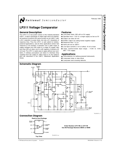
TL H 5711LP311Voltage ComparatorFebruary 1995LP311Voltage ComparatorGeneral DescriptionThe LP311is a low power version of the industry-standard LM311 It takes advantage of stable high-value ion-implant-ed resistors to perform the same function as an LM311 with a 30 1reduction in power drain but only a 6 1slowdown of response time Thus the LP311is well suited for battery-powered applications and all other applications where fast response is not needed It operates over a wide range of supply voltages from 36V down to a single 3V supply with less than 200m A drain but it is still capable of driving a 25mA load The LP311is quite easy to apply without any oscil-lation if ordinary precautions are taken to minimize stray coupling from the output to either input or to the balance pins (as described in the LM311datasheet Application Hints)FeaturesY Low power drain 900m W on 5V supplyY Operates from g 15V or a single supply as low as 3V Y Output can drive 25mAY Emitter output can swing below negative supply Y Response time 1 2m s Y Same pin-out as LM311Y Low input currents 2nA of offset 15nA of biasYLarge common-mode input range b 14 6V to 13 6V with g 15V supplyApplicationsY Level-detector for battery-powered instruments Y Low-power lamp or relay driver YLow-power zero-crossing detectorSchematic DiagramTL H 5711–7Connection DiagramDual-In-Line PackageTL H 5711–4Top ViewOrder Number LP311M or LP311N See NS Package Numbers M08A or N08EC 1995National Semiconductor CorporationRRD-B30M115 Printed in U S AAbsolute Maximum RatingsIf Military Aerospace specified devices are required please contact the National Semiconductor Sales Office Distributors for availability and specifications Total Supply Voltage(V8–4)36V Collector Output to Negative Supply Voltage(V7–4)40V Collector Output to Emitter Output40V Emitter Output to Negative Supply Voltage(V1–4)g30V Differential Input Voltage g30V Input Voltage(Note1)g15V Power Dissipation(Note2)500mW Output Short Circuit Duration10sec Operating Temperature Range0 C to70 C Storage Temperature Range b65 C to150 C Lead Temperature(Soldering 10seconds)260 CElectrical CharacteristicsThese specifications apply for V S e g15V and0 C s T A s70 C unless otherwise specifiedParameter Conditions Min Typ Max Units Input Offset Voltage(Notes3 4)T A e25 C R S s100k2 07 5mVInput Offset Current(Notes3 4)T A e25 C2 025nA Input Bias Current(Note3)T A e25 C15100nA Voltage Gain T A e25 C R L e5k40200V mV Response Time(Note5)T A e25 C1 2m sSaturation Voltage(Note6)V IN s b10mV I OUT e25mA0 41 5VT A e25 CStrobe Current(Note7)T A e25 C100200300m AOutput Leakage Current V IN t10mV V OUT e35V0 2100nAT A e25 CInput Offset Voltage(Notes3 4)R S s100k10mV Input Offset Current(Notes3 4)35nA Input Bias Current(Note3)150nA Input Voltage Range V b a0 5a13 7 b14 7V a b1 5VSaturation Voltage(Note6)V a t4 5V V b e0V0 10 4VV IN s b10mV I SINK s1 6mAPositive Supply Current T A e25 C Output on150300m A Negative Supply Current T A e25 C80180m A Minimum Operating Voltage T A e25 C3 03 5V Note1 This rating applies for g15V supplies The positive input voltage limit is30V above the negative supply The negative input voltage limit is equal to the negative supply voltage or30V below the positive supply whichever is lessNote2 The maximum junction temperature of the LP311is85 C For operating at elevated temperatures devices in the dual-in-line package must be derated based on a thermal resistance of160 C W junction to ambientNote3 The offset voltage offset current and bias current specifications apply for any supply voltage from a single4V supply up to g15V suppliesNote4 The offset voltages and offset currents given are the maximum values required to drive the output within a volt of either supply with1mA load Thus these parameters define an error band and take into account the worst-case effects of voltage gain and input impedanceNote5 The response time specified is for a100mV input step with5mV overdriveNote6 Saturation voltage specification applies to collector-emitter voltage(V7-1)for V COLLECTOR s(V a b3V)Note7 This specification gives the range of current which must be drawn from the strobe pin to ensure the output is properly disabled Do not short the strobe pin to ground It should be current driven 100m A to300m A2Typical Performance CharacteristicsInput Characteristics Input Bias Current Input Offset CurrentCommon Mode Limits Transfer Function Output Saturation Voltage (Collector Output)Response Time for Various Input Overdrives Response Time for VariousInput OverdrivesOutput Saturation Voltage(Emitter Output)Response Time for Various Input Overdrives Response Time for VariousInput OverdrivesOutput LimitingCharacteristicsTL H 5711–5 3Typical Performance Characteristics(Continued)Supply CurrentSupply CurrentLeakage CurrentsTL H 5711–6Applications InformationFor applications information and typical applications refer to the LM311datasheetAuxiliary CircuitsStrobingTL H 5711–1Note Do not ground strobe pinOffset BalancingTL H 5711–2Test CircuitsTest Circuit 1(Collector Output)TL H 5711–8Test Circuit 2(Emitter Output)TL H 5711–9Test Circuit 3(Collector Output)TL H 5711–10Test Circuit 4(Emitter Output)TL H 5711–114Physical Dimensions inches(millimeters)Order Number LP311MNS Package Number M08A5L P 311V o l t a g e C o m p a r a t o rPhysical Dimensions inches (millimeters)(Continued)Molded Dual-In-Line Package (N)Order Number LP311N NS Package Number N08ELIFE SUPPORT POLICYNATIONAL’S PRODUCTS ARE NOT AUTHORIZED FOR USE AS CRITICAL COMPONENTS IN LIFE SUPPORT DEVICES OR SYSTEMS WITHOUT THE EXPRESS WRITTEN APPROVAL OF THE PRESIDENT OF NATIONAL SEMICONDUCTOR CORPORATION As used herein 1 Life support devices or systems are devices or 2 A critical component is any component of a life systems which (a)are intended for surgical implant support device or system whose failure to perform can into the body or (b)support or sustain life and whose be reasonably expected to cause the failure of the life failure to perform when properly used in accordance support device or system or to affect its safety or with instructions for use provided in the labeling can effectivenessbe reasonably expected to result in a significant injury to the userNational Semiconductor National Semiconductor National Semiconductor National Semiconductor CorporationEuropeHong Kong LtdJapan Ltd1111West Bardin RoadFax (a 49)0-180-530858613th Floor Straight Block Tel 81-043-299-2309。

高密度脂蛋白胆固醇测定试剂盒(直接法-过氧化氢酶清除法) 适用范围:用于体外定量检测人血清中高密度脂蛋白胆固醇浓度。
1.1包装规格a) 试剂1:2×60ml,试剂2:2×20ml;b) 试剂1:4×60ml,试剂2:4×20ml;c) 试剂1:3×60ml,试剂2:3×20ml;d) 试剂1:2×45ml,试剂2:2×15ml;e)试剂1:1×45ml,试剂2:1×15ml;f)试剂1:2×16.8ml,试剂2:2×5.6ml;g)试剂1:2×300ml,试剂2:2×100ml。
1.2主要组成成分试剂1主要组成成分试剂2主要组成成分2.1 外观和性状2.1.1 试剂盒各组分应齐全、完整、液体无渗漏;外包装完好、无破损,标签完好、字迹清晰。
2.1.2 试剂1应为无色或淡黄色透明溶液;试剂2应为无色或淡黄色透明溶液。
2.2 净含量应不低于试剂瓶标示装量。
2.3 试剂空白吸光度测定试剂空白吸光度,应<0.05。
2.4 分析灵敏度测试1.0mmol/L样本时,吸光度变化(△A)应大于0.04。
2.5 准确度用参考物质(GBW09178-GBW09180)对试剂(盒)进行测试,测定值与靶值相对偏差不超过±10%。
2.6 精密度2.6.1重复性在重复性条件下,测试浓度正常值和高值的样本,各重复测定不少于10次,变异系数(CV)应不超过4%。
2.6.2批间差抽取3个不同批号试剂,测试同一浓度的样品进行重复检测,每个批号试剂检测3次,批间相对极差应不大于10%。
2.7 线性试剂盒线性在(0.05,3.90)mmol/L范围内:2.7.1线性回归的相关系数应不低于0.995;2.7.2 (0.05,1.00]mmol/L区间内,线性偏差不超过±0.1mmol/L2.7.3(1.00,3.90)mmol/L区间内,线性偏差不超过±10%。


USA SAFETY DATA SHEET3000010060831. CHEMICAL PRODUCT AND COMPANY IDENTIFICATIONProduct name: VERSILOK 331Product Use/Class:Acrylic Adhesive, Part 2 of 2LORD Corporation 111 LORD DriveCary, NC 27511-7923 USATelephone: 814 868-3180Non-Transportation Emergency: 814 763-2345 Chemtrec 24 Hr Transportation Emergency No.800 424-9300 (Outside Continental U.S. 703 527-3887)EFFECTIVE DATE: 03/20/20182. HAZARDS IDENTIFICATIONGHS CLASSIFICATION:Skin corrosion/irritation Category 2Serious eye damage/eye irritation Category 2A Skin sensitization Category 1Hazardous to the aquatic environment - acute hazard Category 2 Hazardous to the aquatic environment - chronic hazard Category 2GHS LABEL ELEMENTS:Symbol(s)Signal WordW ARNINGHazard StatementsCauses skin irritation.Causes serious eye irritation.May cause an allergic skin reaction. Toxic to aquatic life.Toxic to aquatic life with long lasting effects.Precautionary Statements PreventionWear protective gloves/eye protection/face protection. Avoid breathing dust/fume/gas/mist/vapors/spray. Wash thoroughly after handling.Contaminated work clothing should not be allowed out of the workplace. Avoid release to the environment.ResponseSpecific treatment (see supplemental first aid instructions on this label). IF ON SKIN: Wash with plenty of soap and water.If skin irritation or rash occurs: Get medical advice/attention.IF IN EYES: Rinse cautiously with water for several minutes. Remove contact lenses, if present and easy to do. Continue rinsing.If eye irritation persists: Get medical advice/attention. Take off contaminated clothing and wash before reuse.Collect spillage.StorageRefer to Section 7 of this SDS.Disposal:Dispose of contents/container in accordance with waste/disposal laws and regulations of your country or particular locality.Other Hazards:This product contains component(s) which have the following warnings; however based on the GHS classification criteria of your country or locale, the product mixture may be outside the respective category(s).Acute: May be harmful if swallowed. Ingestion is not an expected route of entry in industrial or commercial uses.Chronic: Crystalline silica is classified by IARC and NTP as a known human carcinogen as a respirable dust. The silica in LORD products is not in a form that can be inhaled and presents no risk to the end user. No exposure isexpected during normal use of this product. Sanding or abrading the cured materials is not recommended. Wear appropriate respiratory protection if exposure to dusts is possible. Prolonged exposure to the silica-containing sanding dust of this product could cause long-term lung damage.3. COMPOSITION/INFORMATION ON INGREDIENTSChemical Name CAS Number RangeEpoxy resin PROPRIETARY55 - 60%Benzoyl peroxide94-36-0 1 - 5%Crystalline silica14808-60-70.1 - 0.9%Any "PROPRIETARY" component(s) in the above table is considered trade secret, thus the specific chemical and its exact concentration is being withheld.4. FIRST AID MEASURESFIRST AID - EYE CONTACT: Flush eyes immediately with large amount of water for at least 15 minutes holding eyelids open while flushing. Get prompt medical attention.FIRST AID - SKIN CONTACT: Flush contaminated skin with large amounts of water while removing contaminated clothing. Wash affected skin areas with soap and water. Get medical attention if symptoms occur.FIRST AID - INHALATION: Move person to fresh air. Restore and support continued breathing. If breathing is difficult, give oxygen. Get immediate medical attention.FIRST AID - INGESTION: If swallowed, do not induce vomiting. Call a physician or poison control center immediately for further instructions. Never give anything by mouth if victim is rapidly losing consciousness, unconscious or convulsing.5. FIRE-FIGHTING MEASURESSUITABLE EXTINGUISHING MEDIA: Carbon Dioxide, Dry Chemical, Foam, Water FogUNSUITABLE EXTINGUISHING MEDIA: Not determined for this product.SPECIFIC HAZARDS POSSIBLY ARISING FROM THE CHEMICAL: Keep containers tightly closed. Closed containers may rupture when exposed to extreme heat. Use water spray to keep fire exposed containers cool. During a fire, irritating and/or toxic gases and particulate may be generated by thermal decomposition or combustion.SPECIAL PROTECTIVE EQUIPMENT AND PRECAUTIONS FOR FIRE-FIGHTERS: Wear full firefighting protective clothing, including self-contained breathing apparatus (SCBA). If water is used, fog nozzles are preferable.6. ACCIDENTAL RELEASE MEASURESPERSONAL PRECAUTIONS, PROTECTIVE EQUIPMENT, AND EMERGENCY PROCEDURES: Avoid breathing vapors. Avoid contact. Use appropriate respiratory protection for large spills or spills in confined area. ENVIRONMENTAL PRECAUTIONS: Do not contaminate bodies of water, waterways, or ditches, with chemical or used container.METHODS AND MATERIALS FOR CONTAINMENT AND CLEANUP: Notify appropriate authorities if necessary. Avoid contact. Keep non-essential personnel away from spill area. Scoop spilled material into an appropriate container for proper disposal. (If necessary, use inert absorbent material to aid in containing the spill).7. HANDLING AND STORAGEHANDLING: Keep closure tight and container upright to prevent leakage. Avoid skin and eye contact. Wash thoroughly after handling. Do not handle until all safety precautions have been read and understood.STORAGE: Store only in well-ventilated areas. Keep container closed when not in use.INCOMPATIBILITY: Amines, acids, water, hydroxyl, or active hydrogen compounds.8. EXPOSURE CONTROLS/PERSONAL PROTECTIONCOMPONENT EXPOSURE LIMITChemical Name ACGIH TLV-TWA ACGIH TLV-STELOSHA PEL-TWAOSHA PEL-CEILINGSkinEpoxy resin N.E.N.E.N.E. N.E.N.A.Benzoyl peroxide 5 mg/m3N.E. 5 mg/m3 N.E.N.A.Crystalline silica0.05 mg/m3N.E.N.E. N.E.N.A.N.A. - Not Applicable, N.E. - Not Established, S - Skin DesignationEngineering controls: Sufficient ventilation in pattern and volume should be provided in order to maintain air contaminant levels below recommended exposure limits.PERSONAL PROTECTION MEASURES/EQUIPMENT:RESPIRATORY PROTECTION: Use a NIOSH approved air-purifying organic vapor respirator if occupational limits are exceeded. For emergency situations, confined space use, or other conditions where exposure limits may be greatly exceeded, use an approved air-supplied respirator. Use NIOSH approved dust respirator if occupational limits are exceeded or if product airborne dust conditions are present in the work area. For respirator use observe OSHA regulations (29CFR 1910.134) or use in accordance with applicable laws and regulations of your country or particular locality.SKIN PROTECTION: Use neoprene, nitrile, or rubber gloves to prevent skin contact.EYE PROTECTION: Use safety eyewear including safety glasses with side shields and chemical goggles where splashing may occur.OTHER PROTECTIVE EQUIPMENT: Use disposable or impervious clothing if work clothing contamination is likely. Remove and wash contaminated clothing before reuse.HYGIENIC PRACTICES: Wash hands before eating, smoking, or using toilet facility. Food or beverages should not be consumed anywhere this product is handled or stored. Wash thoroughly after handling.9. PHYSICAL AND CHEMICAL PROPERTIESTypical values, not to be used for specification purposes.ODOR: Epoxy VAPOR PRESSURE: N.D.APPEARANCE: Gray VAPOR DENSITY: Heavier than Air PHYSICAL STATE: Paste LOWER EXPLOSIVE LIMIT: Not ApplicableFLASH POINT:≥ 201 °F, 93 °CSetaflash Closed CupUPPER EXPLOSIVE LIMIT: Not ApplicableBOILING RANGE: N.A.EVAPORATION RATE: Not Applicable AUTOIGNITION TEMPERATURE:N.D.DENSITY: 1.45 g/cm3 - 12.08 lb/gal DECOMPOSITION TEMPERATURE:N.D. VISCOSITY, DYNAMIC: N.D.ODOR THRESHOLD: N.D.VISCOSITY, KINEMATIC: N.D.SOLUBILITY IN H2O: Insoluble VOLATILE BY WEIGHT: 0.25 %pH: N.A.VOLATILE BY VOLUME: 0.32 % FREEZE POINT: N.D. VOC CALCULATED: 0 lb/gal, 1 g/lCOEFFICIENT OF WATER/OILDISTRIBUTION: N.D. TESTED WITH VERSILOK500 VLC:0.99 %VOC EPA Method 24 is evaluated in combination with Versilok 500VLCLEGEND: N.A. - Not Applicable, N.E. - Not Established, N.D. - Not Determined10. STABILITY AND REACTIVITYHAZARDOUS POLYMERIZATION: Hazardous polymerization will not occur under normal conditions. STABILITY: Product is stable under normal storage conditions.CONDITIONS TO AVOID: High temperatures.INCOMPATIBILITY: Amines, acids, water, hydroxyl, or active hydrogen compounds.HAZARDOUS DECOMPOSITION PRODUCTS: Carbon monoxide, carbon dioxide, aldehydes11. TOXICOLOGICAL INFORMATIONEXPOSURE PATH: Refer to section 2 of this SDS.SYMPTOMS:Refer to section 2 of this SDS.TOXICITY MEASURES:Chemical Name LD50/LC50Epoxy resin Oral LD50: Rat11,400 mg/kgBenzoyl peroxide Oral LD50: Rat7,710 mg/kgCrystalline silica N.D.Germ cell mutagenicity: No classification proposedCarcinogenicity: No classification proposedReproductive toxicity: No classification proposed12. ECOLOGICAL INFORMATIONECOTOXICITY:Chemical Name EcotoxicityEpoxy resin N.D.Benzoyl peroxide N.D.Crystalline silica N.D.PERSISTENCE AND DEGRADABILITY:Not determined for this product. BIOACCUMULATIVE: Not determined for this product.MOBILITY IN SOIL: Not determined for this product.OTHER ADVERSE EFFECTS: Not determined for this product.13. DISPOSAL CONSIDERATIONSDISPOSAL METHOD: Disposal should be done in accordance with Federal (40CFR Part 261), state and local environmental control regulations. If waste is determined to be hazardous, use licensed hazardous waste transporter and disposal facility.14. TRANSPORT INFORMATIONUS DOT RoadDOT Proper Shipping Name: Environmentally hazardous substances, liquid, n.o.s.DOT Hazard Class: 9SECONDARY HAZARD: NoneDOT UN/NA Number: 3082Packing Group: IIIEmergency Response Guide Number: 171For US DOT non-bulk road shipments this material may be classified as NOT REGULATED. For the mostaccurate shipping information, refer to your transportation/compliance department regarding changes inpackage size, mode of shipment or other regulatory descriptors.IATA CargoPROPER SHIPPING NAME: Environmentally hazardous substance, liquid, n.o.s.DOT Hazard Class: 9HAZARD CLASS: NoneUN-NUMBER: 3082PACKING GROUP: IIIEMS: 9LIMDGPROPER SHIPPING NAME: Environmentally hazardous substance, liquid, n.o.s.DOT Hazard Class: 9HAZARD CLASS: NoneUN-NUMBER: 3082PACKING GROUP: IIIEMS: F-AThe listed transportation classification applies to non-bulk shipments. It does not address regulatory variations due to changes in package size, mode of shipment or other regulatory descriptors. For the most accurate shipping information, refer to your transportation/compliance department.15. REGULATORY INFORMATIONU.S. FEDERAL REGULATIONS: AS FOLLOWS:SARA SECTION 313This product contains the following substances subject to the reporting requirements of Section 313 of Title III of the Superfund Amendment and Reauthorization Act of 1986 and 40 CFR part 372.:Chemical Name CAS Number Weight % Less ThanBenzoyl peroxide94-36-0 5.0%TOXIC SUBSTANCES CONTROL ACT:INVENTORY STATUSOne or more chemical substances in this product are not yet on the TSCA section 8 inventory. Consequently, this product is presently available only in quantities necessary for research and development purposes as defined by TSCA.The potential health and environmental risks associated with these new chemical substances are not fully characterized.Thus the use of this product is restricted to those technically qualified individuals having the authority to manage the use, storage, or handling of the product so as to minimize any risks.EXPORT NOTIFICATIONThis product contains the following chemical substances subject to the reporting requirements of TSCA 12(B) if exported from the United States:None16. OTHER INFORMATIONUnder HazCom 2012 it is optional to continue using the HMIS rating system. It is important to ensure employees have been trained to recognize the different numeric ratings associated with the HazCom 2012 and HMIS schemes.HMIS RATINGS - HEALTH: 2 FLAMMABILITY: 1 PHYSICAL HAZARD: 1* - Indicates a chronic hazard; see Section 2Revision: Section 2, Section 3, Section 8, Section 11, Section 12Effective Date: 03/20/2018DISCLAIMERThe information contained herein is, to the best of our knowledge and belief, accurate. However, since the conditions of handling and use are beyond our control, we make no guarantee of results, and assume no liability for damages incurred by use of this material. It is the responsibility of the user to comply with all applicable federal, state and local laws and regulations.。

高密度脂蛋白胆固醇测定试剂盒(直接法-选择抑制法) 适用范围:本品用于体外定量测定人血清中高密度脂蛋白的含量。
1.1规格规格1: (试剂1:15mL;试剂2: 5mL);规格2: (试剂1:30mL;试剂2:10mL); .规格3: (试剂1:60mL;试剂2:20mL);规格4: (试剂1:90mL;试剂2:30mL);校准品(冻干品):为选配规格1(0.3mL×1;1水平);规格2(0.5mL×1;1水平);规格3(1.0mL×1;1水平);质控品(冻干品):为选配规格1(0.5mL×2;2水平);规格2(1.0mL×2;2水平)。
1.2组成试剂盒组成见表1表1 高密度脂蛋白胆固醇测定试剂盒组成2.1试剂2.1.1外观试剂盒外观应整洁,文字符号标识清晰;各组分齐全完整,液体无漏液;试剂1为透明液体,不得有沉淀和絮状物;试剂2为浅黄色澄清液体,不得有沉淀和絮状物。
2.1.2装量每瓶不少于标示值。
2.1.3试剂空白吸光度用指定的空白样品测试试剂(盒),37℃条件下,光径1cm,在A600nm 处测定试剂空白吸光度A<0.05。
2.1.4分析灵敏度测定1.0mmol/L的样品,吸光度差值△A>0.04。
2.1.5线性范围2.1.5.1在[0.05,4.0] mmol/L内,相关系数R≥0.995。
2.1.5.2在[0.05,1.0] mmol/L内,线性绝对偏差不超过±0.1mmol/L;(1.0,4.0] mmol/L内,线性相对偏差不超过±10%。
2.1.6 重复性重复测试(0.8±0.2)mmol/L和(1.5±0.5)mmol/L样本,所得结果的变异系数(CV%)应不大于4%。
2.1.7批间差测定(0.8±0.2)mmol/L和(1.5±0.5)mmol/L样本,所得结果的批间相对极差(R)应不大于10%。

产品编号日期■样件□试生产□量产序号特性标识检测频次1C 2C 3C1D 2D 3D 4D 5D 6D 7D 8D 9D 10D 11D 12D 13D审核固定页活动页销轴关键特性(CC)统计控制或防错侧门铰链总成静态纵向载荷铰链应能承受11000N的纵向载荷,不得脱开静态横向载荷铰链应能承受9000N的横向载荷,不得脱开有毒有害物质限量要求特殊特性清单产品名称侧门铰链总成6RM.831.401/6RM.831.402/6RM.831.401.A/6RM.831.402.A 2018.1.30有毒有害物质限量要求符合:铅(Pb)<1000mg/Kg 、汞(Hg)<1000mg/Kg、镉(Cd) <100mg/Kg、六价铬(Cr6+)<1000mg/Kg、多溴联苯(PBB) <1000mg/Kg、多溴二苯醚(PBDE) <1000mg/Kg ,禁止含石棉27±0.15零件名称特性描述特性值检测方法特殊特性(SC)固定页中心高度54±0.2活动页中心高度24±0.15耐久性试验铰链在进行50000~100000次循环之后没有功能降低没有干扰乘客的严重噪声( 由各自的质保部门确定)相对于供货状态扭转力矩改变最大20%无间隙无明显的磨损固定页板平面度活动页到销轴中心距离小组会签铰链操作力在 2 个操作后并对整个寿命周期(0.2~3.0)Nm;在210 ℃下存放2 h 并冷却到室温(0.1~3.0)Nm盐雾试验96 h DIN 50021-SS 喷雾试验和72 h DIN 50017-KFW气候试验在试验后零件必须没有基体金属腐蚀和干扰噪音出现。
允许操纵和止动力矩改变最大20% ,相对于原始状态侧门铰链总成固定页到盲孔中心距离26.5±0.2活动页板平面度编制批准开启角度74°±3°销轴尺寸活动页销轴孔固定页销轴孔。
outside and free of fingerprints, oil and dirt.• Wipe the cuvette thoroughly with HI731318 microfiber cleaning cloth or a lint-free cloth prior to insertion.• Shaking the cuvette can generate bubbles, causing higherbubbles by swirling or by gently tapping the cuvette.• Do not let the reacted sample stand too long after reagent has been added, as accuracy will be affected.• Discard the sample immediately after the reading has been taken or the glass might become permanently stained.• Keep the tips with their appropriate syringes during measurement. Clean the syringes and tips before storage. Battery ReplacementWhen the battery is drained, the instrument displays “bAd” then ”bAt”, and turns off. To replace the battery, follow the next steps:1. Press and hold the ON/OFF button to turn the checker off.2. Turn the instrument upside down and use a screwdriver to unfasten the screw and remove the battery cover.3. Remove the old battery, replace it with a new 1.5V AAA battery, inserting the negative end first.4. Replace the battery cover, fasten and tighten the screw.To save the battery, the checker shuts down after 10 minutes of non-use.A fresh battery lasts for a minimum of 5000 measurements.AccessoriesReagent SetsHI783-25Reagents for 25 Marine Magnesium testsOther AccessoriesHI783-11Marine Magnesium certified standard kitHI731315Glass cuvette and cap for Checker®HC colorimeters (2 pcs.)HI731318Cloth for wiping cuvettes (4 pcs.)HI740028P 1.5V AAA battery set (12 pcs.)HI740143 1 mL graduated syringe (6 pcs.)HI740144P Plastic pipette tip (10 pcs.)HI740226 5 mL graduated syringe with black printing (1 pc.)HI740237 5 mL graduated syringe with blue printing (1 pc.)HI740274Syringe replacement kitHI93703-50Cuvette cleaning solution, 230 mLHI783Marine MagnesiumAll rights are reserved. Reproduction in whole or in part is prohibited without thewritten consent of the copyright owner, Hanna Instruments Inc., Woonsocket,Rhode Island, 02895, USA.IST783 02/22-1CertificationAll Hanna® instruments conform to the CE European Directives.Disposal of Electrical & Electronic Equipment. The productshould not be treated as household waste. Instead, hand it overto the appropriate collection point for the recycling of electricaland electronic equipment, which will conserve natural resources.Disposal of waste batteries. This product contains batteries, donot dispose of them with other household waste. Hand them overto the appropriate collection point for recycling.Ensuring proper product and battery disposal prevents potential negativeconsequences for the environment and human health. For more information, contactyour city, your local household waste disposal service, or the place of purchase.Recommendations for UsersBefore using this product, make sure it is entirely suitable for your specificapplication and for the environment in which it is used. Any variation introducedby the user to the supplied equipment may degrade the checker’s performance.For your and the checker’s safety do not use or store it in hazardous environments.WarrantyHI783 Checker HC is warranted for a period of one year against defects inworkmanship and materials when used for its intended purpose and maintainedaccording to instructions. This warranty is limited to repair or replacementfree of charge. Damage due to accidents, misuse, tampering, or lack ofprescribed maintenance is not covered. If service is required, contact your localHanna Instruments® office. If under warranty, report the model number, date ofpurchase, serial number, and the nature of the problem. If the repair is not coveredby the warranty, you will be notified of the charges incurred. If the checker is to bereturned to Hanna Instruments, first obtain a Returned Goods Authorization (RGA)number from the Technical Service department and then send it with shippingcosts prepaid. When shipping any product, make sure it is properly packaged forcomplete protection.Hanna Instruments reserves the right to modify the design, construction, orappearance of its products without advance notice.Measurement Procedure1. Ensure cuvettes, syringes, and tips are completely clean and dry before use.See reverse side for tips on measuring liquids using syringes.2. Press the ON/OFF button to turn the checker on. All segments will be displayed for a few seconds, followed by “Add”,3. Preparing the cuvette for “C.1” measurements:• Place the syringe tips onto each syringe. Ensure the O-rings remain in the tip for a proper seal.• Use the 5 mL syringe with black printing to measure 4 mL of HI783A-0 reagent. Ensure there is no excess reagent on the syringe tip, then slowly dispense the 4 mL of reagent into aclean, dry cuvette. If excessive reagent remains in the tip,draw a small amount of air into the syringe and use it to expel the remaining reagent into the cuvette.Ensure there is no excess sample on the syringe tip, then slowly dispense the sample into the same cuvette. Ensure no sample is remaining in the tip.Note: 5 times, until the solution has been thoroughly mixed. Ensure there are no bubbles in the mixture and that the outside of the cuvette is dry and clean.• Insert the cuvette into the checker and close the cap.• Press the ON/OFF button. When the display shows “Add”, “C.2” with “Press” blinking, the checker is zeroed. Remove the cuvette.4. Preparing the cuvette for “C.2” measurements:• Unscrew the cap and use the 1 mL syringe to dispense 1 mL of HI783B-0 reagent into the cuvette. Gently clean any excess liquid outside of the tip. Ensure no liquid is left in the tip. Screw the cap onto the cuvette.Preliminary ExaminationRemove the CheckerHC handheld colorimeter and accessories from the packing material and examine it carefully. If you require any further information, please contact Hanna Instruments technical support team.Each HI783 is delivered in a case with custom insert and is supplied with:• Sample cuvette and cap (2 pcs.)• Marine Magnesium reagent starter kit (reagents for 25 tests)• 1 mL graduated syringe and tip (1 pc.)• 5 mL syringe and tip with black printing (1 pc.)• 5 mL syringe and tip with blue printing (1 pc.)• 1.5V AAA Alkaline battery (1 pc.)• Instruction manual • Quick-reference guideNote: Save all packing material until you are sure that the Checker HC handheld colorimeter works correctly. Any damaged or defective item must be returned in its original packing material with the supplied accessories.General Description & Intended UseHI783 Marine Magnesium handheld checker is designed to determine the concentration of magnesium in saltwater aquariums.HI783 features a single-button operation system and is easy to use.The large LCD is easy to read and the auto shut-off feature assures the battery will not be drained.SpecificationsRange 1000 to 1800 ppm Magnesium Resolution 5 ppmAccuracy ±5% of reading @ 25 °C (77 °F)Light source Light Emitting Diode @ 610 nm Light detector Silicon photocellMethodAdaptation of the colorimetric EDTA method using calmagite indicator. The reaction between magnesium and the reagents causes a blue to violet tint in the sample.Environment 0 to 50 °C (32 to 122 °F); max. 95% RH non-condensing Prepared sample cuvette (sample plus reagents) must be 18 to 28 °C (64 to 82 °F).*Battery type 1.5V AAA AlkalineAuto shut-off After 10 minutes of non-useDimensions 86.0 x 61.0 x 37.5 mm (3.4 x 2.4 x 1.5”)Weight 64 g (2.3 oz)InterferencesCalcium below 300 ppm and above 500 ppm* Warm or cool prepared cuvettes if needed.Functional Description & LCD DisplayCapCuvette with cap Cuvette holderLCD (Liquid Crystal Display)ON/OFF button• Gently invert the cuvette 5 times until the solution has been thoroughly mixed. For the most accurate reading, ensure there are no visible bubbles.• Insert the cuvette into the checker and close the cap.5. Press ON/OFF button. The instrument displays theppm of magnesium. The checker automatically turns off 10 minutes after reading.6. Rinse cuvettes, caps, syringes, and tips thoroughly with deionized (RODI) water and allow to dry completely before storing.Errors & WarningsThe checker shows clear warning messages when erroneous conditions appear and when measured values are outside the expected range. The information below provides an explanation of the errors and warnings, and the recommended action to be taken.Light High: There is an excess amount of ambient light reaching the detector. Please check the preparation of the zero cuvette.Light Low: There is not enough light to perform a measurement. Please check the preparation of the zero cuvette.Under Range: Minimum concentration value displayed blinking indicates the measured value is outside the limits of the method. Verify that the sample does not contain any debris, and the preparation of the sample cuvette.Over Range:blinking indicates the measured value is outside the limits of the method. Verify the preparation of the sample cuvette. Dilute the sample and repeat the measurement.Battery Low: Battery level is too low for the checker to function properly. Replace the battery with a new one.Drained Battery: The battery is drained and must be replaced. Replace the battery with a new one and restart the checker.1350。
GENERALThe CA51/CA71 HANDY CAL calibrators arecomprehensive generating/measuring instruments for all your calibration and equipment checking needs at maintenance sites. The CA51/CA71 can simultaneously generate and measure voltage, current, TC, RTD and pulse signals, thus you don’t need to prepare manyinstruments. In addition, the incorporated rotaryswitches of good repute enable operations so smooth that an incorrect measurement caused from erroneous operations can be prevented.FEATURESSimultaneous signal generation and measurement capabilityThe CA71 lets you handle regular tests on TCs, RTDs and various other types of sensors and instruments, as well as operation checks when a problem has occurred. By itself it can generate signals for input to equipment, and check output signal from equipment.(TC and RTD measurement functions: CA71 only)AC voltage (including supply voltage) measurement capabilityIn cases where numerous signal converters and other devices are mounted on a rack or panel, the CA51/CA71 can be used to check the input and output signals of each device, while simultaneously checking the power supply. There is no need for a separate multimeter to measure supply voltage.A wide array of useful functionsDivided output (n/m) function, Auto-step function,Sweep function, Memory function and Communication function are available.(Communication function: CA71 only)Easy OperationThe CA51/CA71 incorporates rotary switches for simple handling. Just open the cover of carrying case and connect the cables, and you are ready to take measurement.FUNCTIONSGeneration and MeasurementGeneration and Measurement of Voltage/Current The CA51/CA71 can generate voltage/current up to 30 V DC/24 mA DC and measure up to 100 V DC/100 mA DC.4−20 mA Step FunctionYou can set the signal in 4 mA increments or decrements in order 4 ⇔ 8 ⇔ 12 ⇔ 16 ⇔ 20 mA by one touch operation.20 mA SINK FunctionThe 20 mA SINK function can draw current from an external voltage source to the H terminal of SOURSE unit. Thus, the CA51/CA71 can be used in a loop test, for example, as a simulator for transmitters.Example of Connectiondistributor.Equivalent Output of TC/RTDIn addition to10 types of TC (K, E, J, T, N, L, U, R, S and B), RTD (Pt100, JPt100) outputs are available.The CA51/CA71 can be used for maintenance of industrial instruments for process or various thermometers.Multi TemperatureThe CA51/CA71 can be used as multi thermometerbecause the measurements for all ranges are available. For RTD, 3-wire measurement is available.Built-in Reference Junction Compensation Sensor As a means of easily providing reference junctioncompensation when TC is generated, you can use the temperature sensor within the CA51/CA71. For more accurate reference junction compensation, use RJ sensor (model: B9108WA) sold separately. Example of ConnectionCA71 and the instrument to be calibrated.Instrument to be calibrated(Temperature controller, temperature converter or the like)General SpecificationsGS 77W02A01-01-E Model CA51/ CA71 HANDY CAL calibratorGeneration and Measurement of PulseFrequency can be set in the wide range of 1 Hz to 11 kHz. With switch selection, the CA51/CA71 can generate or measure pulses.It is suitable for checking a flow meter or receiver. Generation and Measurement of Voltage Pulse and Contact PulseThe CA51/CA71 can generate and measure voltage pulse (amplitude: +0.1 V to +15 V, zero base waveform) and contact pulse.Pulse Cycle FunctionThe set pulse can be output. It is suitable for checking integrating counter. (Any value of frequency and amplitude is settable.)CPM (count/min), CPH (count/hour) FunctionIn MEASURE mod (functions for measurement), pulse number per minute is counted. It is suitable for the integration of discontinuous pulse signals from flow meter.In SOURCE mode (functions for generation), you can select either generation of continuous pulse signals or generation of given number of pulses.Example of ConnectionPulse receiver(integrating counter,pulse converter, controlleror the like)Measurement of Commercial Power Supply Voltage AC voltage up to 300 V can be measured. World-wide supply voltage can also be measured.Useful FunctionsDivided Output (n/m) FunctionThe divided output (n/m) function outputs a value n/m times the setpoint of a voltage, current, resistance, TC or RTD signal.When inputting the percentage of instrument input value within the range of zero to full scale, bothersome calculations for percentage is not required..Auto Step FunctionThe auto-step function divides the range of zero to full scale into m equally, increases or decreases the output in a step-by-step manner by changing the variable n of the n/m output from n=0 to m when the divided output function (n/m) is selected.Sweep FunctionThe sweep function linearly increases or decreases the output.Memory FunctionWith a pair of generated and measured signal values in a set, the CA51/CA71 can handle a maximum of 50 sets of data by means of its built-in memory.Communication Function (CA71 only)By connecting the communication cable (RS-232): 91017, you can read internal memory data and measured value, or set the generated signal from a personal computer.SPECIFICATIONSSOURCE unit: Range and AccuracyAccuracy: ±(setting percentage plus µV, mV, mA, Ω or °C)Parameter Reference RangeAccuracy (23±5 °C per year)Resolution Remarks100mV -10.00 to 110.00 mV ± (0.02%+15 µV) 10 µV 1 V0 to 1.1000 V ± (0.02%+0.1 mV) 0.1 mV Maximum output: 5 mA 10 V 0 to 11.000 V ± (0.02%+1 mV) 1 mV Maximum output: 10 mA DC voltage30 V 0 to 30.00 V ± (0.02%+10 mV) 10 mVMaximum output 10 mA *1 20 mA0 to 24.000 mA 1 µADC current4-20 mA4/8/12/16/20 mA ± (0.025%+3 µA)4 mAMaximum load: 12 VmA SINK 20 mA 0.1 to 24.000 mA ± (0.05%+3 µA) 1 µAExternal power supply: 5 to 28 V Resistance 400 Ω0 to 400.00 Ω± (0.025%+0.1 Ω) 0.01 Ω Pt100 *2-200.0 to 850.0 °C RTDJPt100-200.0 to 500.0 °C ± (0.025%+0.3 °C) 0.1 °C Excitation current: 0.5 to 5 mA *3If 0.1 mA, add 0.25 Ω or 0.6°C. Subject device input capacitance: 0.1 µF or lessK -200.0 to 1372.0 °C E -200.0 to 1000.0 °C J -200.0 to 1200.0 °C ± (0.02%+0.5 °C) (-100 °C or greater) ± (0.02%+1 °C) (-100 °C or less) T -200.0 to 400.0 °C N -200.0 to 1300.0 °C L -200.0 to 900.0 °C U -200.0 to 400.0 °C± (0.02%+0.5 °C) (0 °Cor greater) ± (0.02%+1 °C) (0 °C or less) 0.1 °CRS0 to 1768 °C± (0.02%+2.5 °C) (100 °C or less) ± (0.02%+1.5 °C) (100 °C or greater) TC *4B 600 to 1800 °C ± (0.02%+2 °C) (1000 °C or less) ± (0.02%+1.5 °C) (1000 °C or greater) 1 °CTC generation accuracy does not include RJ sensor accuracy.< RJ sensor specs >Measurement range: -10 to 50 °CAccuracy (when combined with main unit) 18 to 28°C: ±0.5°COther than the above: ±1°C500 Hz1.0 to 500.0 Hz ± 0.2 Hz0.1 Hz1000 Hz90 to 1100 Hz± 1 Hz 1 Hz10 kHz 0.9 kHz to 11.0 kHz ± 0.1 kHz 0.1 kHzFrequency, pulsePulse cycle *51 to 99999 cycles- 1 cyclesOutput voltage: +0.1 to 15 V (zero base waveform)Amplitude accuracy: ±(5% + 0.1 V) Maximum load current: 10 mA Contact output(With 0.0 V amplitude setting, FET switch ON/OFF)Maximum open/close voltage/current: +28 V/50 mATemperature coefficient: Accuracy shown above × (1/5)/ °C*1: Output up to 24 V/22 mA is possible when using the AC adapter.*2: As per JIS C 1604-1997 (ITS-90). IPTS-68 may be selected through internal settings (DIP switch). *3: Excitation current: If less than 0.1 mA to 0.5 mA, then add [0.025/Is (mA)]Ω or [0.06/Is (mA)] °C *4: As per JIS C 1602-1995 (ITS-90) (L and U are DIN specs).K, E, J, T, N, R, S, and B may be switched to IPTS-68 through internal settings (DIP switch) (L and U are not switched).*5: Frequency (interval between one pulse and another) and amplitude during pulse cycle generation may have the same range as during frequency generation.MEAURE unit: Range and AccuracyAccuracy: ±(reading percentage plus µV, mV, µA, Ω or dgt (digit))Parameter Reference RangeAccuracy (23±5 °C per year)Resolution Remarks100 mV 0 to ±110.00 mV± (0.025% + 20 µV) 10 µV 1 V0 to ±1.1000 V ± (0.025% + 0.2 mV) 0.1 mV Input resistance: 10 M Ω or greater 10 V 0 to ±11.000 V ± (0.025% + 2 mV) 1 mV DC voltage100 V 0 to ±110.00 V ± (0.05% + 20 mV) 0.01 V Input resistance: Approximately 1 M Ω 20 mA0 to ±24.000 mA ± (0.025% + 4 µA) 1 µA DC current100 mA0 to ±100.00 mA ± (0.04% + 30 µA) 10 µA Input resistance: Approximately 14 ΩResistance 400 Ω0 to 400.00 Ω ± (0.05% + 0.1 Ω) 0.01 Ω Accuracy during 3-wire measurement 1 V0 to 1.100 V 1 mV 10 V0 to 11.00 V 0.01 V Input resistance:Approximately 10 M Ω//10 pF100 V 0 to 110.0 V ± (0.5% + 5 dgt)0.1 V AC voltage300 V0 to 300 V± (0.5% + 2 dgt)1 V Input resistance: Approximately 1M Ω//10 pFInput frequency: 45 to 65 HzInput voltage range : 10 to 100%Measurement method:Average value rectification 100 Hz 1.00 to 100.00 Hz 0.01 Hz 1000 Hz1.0 to 1000.0 Hz 0.1 Hz 10 kHz 0.001 to 11.000 kHz 0.001 kHz CPM1 to 99999 CPM 1 CPM Frequency, pulse CPH1 to 99999 CPH± 2 dgt1 CPHMaximum input: 30 V peakInput resistance: 200 k Ω or greater Sensitivity: 0.5 V peak or greater Contact input: Maximum 100Hz NotesCPM: Counts per minute CPH: Counts per hourTemperature coefficient: Accuracy shown above × (1/5)/ °CMEAURE unit (temperature): Range and Accuracy (CA71 only) Accuracy: ±(reading percentage plus °C) Parameter Reference Range Accuracy(23±5°C per year) Resolution Remarks K -200.0 to 1372.0 °CE -200.0 to 1000.0 °C J -200.0 to 1200.0 °C T -200.0 to 400.0 °C N -200.0 to 1300.0 °C L -200.0 to 900.0 °C U -200.0 to 400.0 °C ± (0.05% + 1.5 °C)(-100 °C or greater)± (0.05% + 2 °C)(-100 °C or less)0.1°CR 0 to 1768 °CS 0 to 1768 °C TC *7B 600 to 1800 °C ± (0.05% + 2 °C)(100 °C or greater)± (0.05% + 3 °C)(100 °C or less)1°CPt100 *6 -200.0 to 850.0 °C RTDJPt100 -200.0 to 500.0 °C ± (0.05% + 6 °C) 0.1°CAccuracy during 3-wiremeasurementTemperature coefficient: Accuracy shown above × (1/5)/°C*6: As per JIS C 1604-1997 (ITS-90). IPTS-68 may be selected through internal settings (DIP switch).*7: As per JIS C 1602-1995 (ITS-90) (L and U are DIN specs).K, E, J, T, N, R, S, and B may be switched to IPTS-68 through internal settings (DIP switch) (L and U are not switched).General SpecificationsParameter SpecificationSOURCE unit response time Approximately 1 second (time between start of voltage change and when voltage enters accuracy range)SOURCE unit voltage limiter Approximately 32 VSOURCE unit current limiter Approximately 25 mADivided output (n/m) function Output=setting× (n/m) n= 0 to m; m = 1 to 19; n ≤ mAuto-step output function n value sent automatically when n/m function is selected (two options: approximately 2.5seconds/step or approximately 5 seconds/step)Sweep function Sweep time (two options: approximately 16 seconds or approximately 32 seconds)Memory function 50 sets of data (generated and measured values are stored as value sets with the same address (upto 50 sets of data can be stored))MEASURE unit maximum input Voltage terminal: 300V DC/ACCurrent terminal: 120 mA DCCurrent terminal input protection Fuses: 125 mA/250 VMEASURE unit ground voltage Maximum 300 V ACMeasurement display updating rate Approximately once per secondSerial interface Enables when communication cable (RS-232) is connected; sold separately as optional accessory(CA71 only)Display Segment LCD (approximately 76 mm × 48 mm)Backlight LED backlight; auto-off after one minute (from when LIGHT key is turned on)Power supply Four AA-size (LR6) alkaline batteries, or special AC adapter (sold separately)Battery life Measurement off, output 5 V DC/10 kΩ or greater: Approximately 40 hours Simultaneous signal generation/measurement, output 5 V DC/10 kΩ or greater: Approximately 20 hoursSimultaneous signal generation/measurement, output 20 mA/5 V: Approximately 12 hours (using alkaline batteries, with backlight off)Consumed power Approximately 7 VA (using 100 V AC adapter)Auto-power-off function Approximately 10 minutes (auto-power-off can be disabled through a DIP switch setting) Standard safety IEC61010-1, EN61010-2-031Emission EN61236-1 Class B, EN61000-3-2, EN61000-3-3 EN55011: Group1, ClassApplicablestandards EMCImmunity EN61326 Annex BInsulation resistance Across input terminal and output terminal, 500V DC, 50 MΩ or greater Withstand voltage Across input terminal and output terminal, 3.7 kV AC, for one minute Operating temperature and humidityranges0 to 50 °C, 20 to 80% RH (no condensation)Storage temperature and humidityranges-20 to 50 °C, 90% RH or less (no condensation)External dimensions (WHD) Approximately 190 × 120 × 55 mmWight Approximately 730 g (including batteries)HARDWARE BLOCK DIAGRAMEXTERNAL DEMENSIONSNote: This figure shows the CA71, but there is no difference in exterior from the CA51.MODELModel Name Remarks CA51 CA51 HANDY CAL calibrator Basic modelCA71 CA71 HANDY CAL calibrator Provided with temperature measurement and communication functionsStandard accessories:Lead cables for source (generation) (one red, two black): 98020Lead cables for measurement (one red, one black): RD031Carrying case: 93016Terminal adapter: 99021User’s manual: IM CA71-EFuse: A1501EF for current terminal input protectionFour AA-size (LR6) alkaline batteries: A1070EB × 4ORDERING INSTRUCTIONSWhen ordering, specify the model and necessary/unnecessary of QIC.OPTIONAL ACCESSORIES AND SPARE PARTSOptional AccessoriesModel Product Remarks A1020UP AC adapter AC adapter for 100 V AC power supplyA1022UP AC adapter AC adapter for 120V AC power supplyB9108WB AC adapter AC adapter for 220 to 240 V AC power supply B9108WA RJ sensor Sensor for reference junction compensationB9108XA Accessories case Lead cable, RJ sensor and the like can be stored.91017 Communication cable 9-pin D-subSpare PartsModel Product Remarks 98020 Lead cables for source (generation)One red, two blackRD031 Lead cables for measurement One red, one black93016 Carryingcase Lead cables for source (generation)/measurement, terminal adapter, four spare batteries, fuse, AC adapter and User’s manuals can be stored.99021 Terminal adapter Used when measuring temperaturesA1501EF Fuse For current terminal input protection (sold by the ten pieces)。
661 CONTAINERS—PLASTICSINTRODUCTIONIt is the purpose of this chapter to provide standards for plastic materials and components used to package medical articles (pharmaceuticals, biologics, dietary supplements, and devices). Definitions that apply to this chapter are provided in the Preservation, Packaging, Storage, and Labeling section of the General Notices and Requirements. Standards and tests for the functional properties of containers and their components areprovided in general chapter Containers—Performance Testing 671.In addition to the standards provided herein, the ingredients added to the polymers, and those used in the fabrication of the containers, must conform to the requirements in the applicable sections of the Code of Federal Regulations, Title 21, Indirect Food Additives, or have been evaluated by the FDA and determined to be acceptable substances for the listed use.Plastic articles are identified and characterized by IR spectroscopy and differential scanning calorimetry. Standards are provided in this chapter for the identification and characterization of the different types of plastic, and the test procedures are provided at the end of the chapter. The degree of testing is based on whether or not the container has direct contact with the drug product, and the risk is based on the route of administration.Plastics are composed of a mixture of homologous polymers, having a range of molecular weights. Plastics may contain other substances such as residues from the polymerization process, plasticizers, stabilizers, antioxidants, pigments, and lubricants. These materials meet the requirements for food contact as provided in the Code of Federal Regulations, Title 21. Factors such as plastic composition, processing and cleaning procedures, surface treatment, contacting media, inks, adhesives, absorption and permeability of preservatives, and conditions of storage may also affect the suitability of a plastic for a specific use. Extraction tests are designed to characterize the extracted components and identify possible migrants. The degree or extent of testing for extractables of the component is dependent on the intended use and the degree of risk to adversely impact the efficacy of the compendial article (drug, biologic, dietary supplement, or device). Resin-specific extraction tests are provided in this chapter for polyethylene, polypropylene, polyethylene terephthalate, and polyethylene terephthalate G. Test all other plastics as directed for Physicochemical Tests in the section Test Methods. Conduct the Buffering Capacity test only when the containers are intended to hold a liquid product.Plastic components used for products of high risk, such as those intended for inhalation, parenteral preparation, and ophthalmics are tested using the Biological Tests in thesection Test Methods.Plastic containers intended for packaging products prepared for parenteral use meet the requirements for Biological Tests and Physicochemical Tests in the section Test Methods. Standards are also provided for polyethylene containers used to package dry oral dosage forms that are not meant for constitution into solution.POLYETHYLENE CONTAINERSScopeThe standards and tests provided in this section characterize containers and components, produced from either low-density polyethylene or high-density polyethylene of either homopolymer or copolymer resins that are interchangeably suitable for packaging dry oral dosage forms not meant for constitution into solution. All polyethylene components are subject to testing by IR spectroscopy and differential scanning calorimetry. Where stability studies have been performed to establish the expiration date of a particular dosage form in the appropriate polyethylene container, then any other polyethylene container meeting these requirements may be similarly used to package such a dosage form, provided that the appropriate stability programs are expanded to include the alternative container, in order to ensure that the identity, strength, quality, and purity of the dosage form are maintained throughout the expiration period.BackgroundHigh-density and low-density polyethylene are long-chain polymers synthesized under controlled conditions of heat and pressure, with the aid of catalysts from not less than 85.0% ethylene and not less than 95.0% total olefins. Other olefin ingredients that are most frequently used are butene, hexene, and propylene. High-density polyethylene and low-density polyethylene both have an IR absorption spectrum that is distinctive for polyethylene, and each possesses characteristic thermal properties. High-density polyethylene has a density between 0.941 and 0.965 g per cm3. Low-density polyethylene has a density between 0.850 and 0.940 g per cm3. Other properties that may affect the suitability of polyethylene include modulus of elasticity, melt index, environmental stress crack resistance, and degree of crystallinity after molding.High-Density PolyethyleneInfrared Spectroscopy— Proceed as directed for Multiple Internal Reflectance in the section Test Methods. The corrected spectrum of the specimen exhibits major absorption bands only at the same wavelengths as the spectrum of USP High-Density Polyethylene RS.Differential Scanning Calorimetry— Proceed as directed for Thermal Analysis in the section Test Methods. The thermogram of the specimen is similar to the thermogram ofUSP High-Density Polyethylene RS, similarly determined, and the temperature of the endotherm (melt) in the thermogram of the specimen does not differ from that of the USP Reference Standard by more than 6.0.Heavy Metals and Nonvolatile Residue— Prepare extracts of specimens for these tests as directed for Physicochemical Tests under Test Methods, except that for each 20.0 mL of Extracting Medium the portion shall be 60 cm2, regardless of thickness.HEAVY METALS— Containers meet the requirements for Heavy Metals in the section Physicochemical Tests under Test Methods.NONVOLATILE RESIDUE— Proceed as directed for Nonvolatile Residue under Physicochemical Tests, except that the Blank shall be the same solvent used in each of the following test conditions: the difference between the amounts obtained from the Sample Preparation and the Blank does not exceed 12.0 mg when water maintained at a temperature of 70 is used as the Extracting Medium; does not exceed 75.0 mg when alcohol maintained at a temperature of 70 is used as the Extracting Medium; and does not exceed 100.0 mg when hexanes maintained at a temperature of 50 is used as the Extracting Medium.Components Used in Contact with Oral Liquids— Proceed as directed for Buffering Capacity in the section Physicochemical Tests under Test Methods.Low-Density PolyethyleneInfrared Spectroscopy— Proceed as directed for Multiple Internal Reflectance under Test Methods. The corrected spectrum of the specimen exhibits major absorption bands only at the same wavelengths as the spectrum of USP Low-Density Polyethylene RS.Differential Scanning Calorimetry— Proceed as directed for Thermal Analysis under Test Methods. The thermogram of the specimen is similar to the thermogram of USP Low-Density Polyethylene RS, similarly determined, and the temperature of the endotherm (melt) in the thermogram of the specimen does not differ from that of the USP Reference Standard by more than 8.0.Heavy Metals and Nonvolatile Residue— Prepare extracts of specimens for these tests as directed for Sample Preparation in the section Physicochemical Tests under Test Methods, except that for each 20.0 mL of Extracting Medium the portion shall be 60 cm2, regardless of thickness.HEAVY METALS— Containers meet the requirements for Heavy Metals in the section Physicochemical Tests under Test Methods.NONVOLATILE RESIDUE— Proceed as directed for Nonvolatile Residue in the section Physicochemical Tests under Test Methods, except that the Blank shall be the same solvent used in each of the following test conditions: the difference between the amountsobtained from the Sample Preparation and the Blank does not exceed 12.0 mg when water maintained at a temperature of 70 is used as the Extracting Medium; does not exceed 75.0 mg when alcohol maintained at a temperature of 70 is used as the Extracting Medium; and does not exceed 350.0 mg when hexanes maintained at a temperature of 50 is used as the Extracting Medium.Components Used in Contact with Oral Liquids— Proceed as directed for Buffering Capacity in the section Physicochemical Tests under Test Methods.POLYPROPYLENE CONTAINERSScopeThe standards and tests provided in this section characterize polypropylene containers, produced from either homopolymers or copolymers, that are interchangeably suitable for packaging dry solid and liquid oral dosage forms. Where suitable stability studies have been performed to establish the expiration date of a particular dosage form in the appropriate polypropylene container, then any other polypropylene container meeting these requirements may be similarly used to package such a dosage form, provided that the appropriate stability programs are expanded to include the alternative container, in order to ensure that the identity, strength, quality, and purity of the dosage form are maintained throughout the expiration period.BackgroundPropylene polymers are long-chain polymers synthesized from propylene or propylene and other olefins under controlled conditions of heat and pressure, with the aid of catalysts. Examples of other olefins most commonly used include ethylene and butene. The propylene polymers, the ingredients used to manufacture the propylene polymers, and the ingredients used in the fabrication of the containers conform to the applicable sections of the Code of Federal Regulations, Title 21.Factors such as plastic composition, processing and cleaning procedures, contacting media, inks, adhesives, absorption, adsorption and permeability of preservatives, and conditions of storage may also affect the suitability of a plastic for a specific use. The suitability of a specific polypropylene must be established by appropriate testing. Polypropylene has a distinctive IR spectrum and possesses characteristic thermal properties. It has a density between 0.880 and 0.913 g per cm3. The permeation properties of molded polypropylene containers may be altered when reground polymer is incorporated, depending on the proportion of reground material in the final product. Other properties that may affect the suitability of polypropylene used in containers for packaging drugs are the following: oxygen and moisture permeability, modulus of elasticity, melt flow index, environmental stress crack resistance, and degree ofcrystallinity after molding. The requirements in this section are to be met when dry solid and liquid oral dosage forms are to be packaged in a container defined by this section.Infrared Spectroscopy— Proceed as directed for Multiple Internal Reflectance under Test Methods. The corrected spectrum of the specimen exhibits major absorption bands only at the same wavelengths as the spectrum of the respective USP Homopolymer Polypropylene RS or copolymer polypropylene standard, similarly determined.Differential Scanning Calorimetry— Proceed as directed for Thermal Analysis under Test Methods. The temperature of the endotherm (melt) in the thermogram does not differ from that of the USP Reference Standard for homopolymers by more than 6.0. The temperature of the endotherm obtained from the thermogram of the copolymer polypropylene specimen does not differ from that of the copolymer polypropylene standard by more than 12.0.Heavy Metals and Nonvolatile Residue— Prepare extracts of specimens for these tests as directed for Sample Preparation in the section Physicochemical Tests under Test Methods, except that for each 20 mL of Extracting Medium the portion shall be 60 cm2, regardless of thickness.HEAVY METALS— Containers meet the requirements for Heavy Metals in the section Physicochemical Tests under Test Methods.NONVOLATILE RESIDUE— Proceed as directed for Nonvolatile Residue in the section Physicochemical Tests under Test Methods, except that the Blank shall be the same solvent used in each of the following test conditions: the difference between the amounts obtained from the Sample Preparation and the Blank does not exceed 10.0 mg when water maintained at a temperature of 70 is used as the Extracting Medium; does not exceed 60.0 mg when alcohol maintained at a temperature of 70 is used as the Extracting Medium; and does not exceed 225.0 mg when hexanes maintained at a temperature of 50 is used as the Extracting Medium. Containers meet these requirements for Nonvolatile Residue for all of the above extracting media. [N OTE—Hexanes and alcohol are flammable. When evaporating these solvents, use a current of air with the water bath; when drying the residue, use an explosion-proof oven. ]Components Used in Contact with Oral Liquids— Proceed as directed for Buffering Capacity in the section Physicochemical Tests under Test Methods.POLYETHYLENE TEREPHTHALATE BOTTLES AND POLYETHYLENETEREPHTHALATE G CONTAINERSScopeThe standards and tests provided in this section characterize polyethylene terephthalate(PET) and polyethylene terephthalate G (PETG) bottles that are interchangeably suitable for packaging liquid oral dosage forms. Where stability studies have been performed to establish the expiration date of a particular liquid oral dosage form in a bottle meeting the requirements set forth herein for either PET or PETG bottles, any other PET or PETG bottle meeting these requirements may be similarly used to package such a dosage form, provided that the appropriate stability programs are expanded to include the alternative bottle in order to ensure that the identity, strength, quality, and purity of the dosage form are maintained throughout the expiration period. The suitability of a specific PET or PETG bottle for use in the dispensing of a particular pharmaceutical liquid oral dosage form must be established by appropriate testing.BackgroundPET resins are long-chain crystalline polymers prepared by the condensation of ethylene glycol with dimethyl terephthalate or terephthalic acid. PET copolymer resins are prepared in a similar way, except that they may also contain a small amount of either isophthalic acid (not more than 3 mole percent) or 1,4-cyclohexanedimethanol (not more than 5 mole percent). Polymerization is conducted under controlled conditions of heat and vacuum, with the aid of catalysts and stabilizers.PET copolymer resins have physical and spectral properties similar to PET and for practical purposes are treated as PET. The tests and specifications provided in this section to characterize PET resins and bottles apply also to PET copolymer resins and to bottles fabricated from them.PET and PET copolymer resins generally exhibit a large degree of order in their molecular structure. As a result, they exhibit characteristic composition-dependent thermal behavior, including a glass transition temperature of about 76 and a melting temperature of about 250. These resins have a distinctive IR absorption spectrum that allows them to be distinguished from other plastic materials (e.g., polycarbonate, polystyrene, polyethylene, and PETG resins). PET and PET copolymer resins have a density between 1.3 and 1.4 g per cm3and a minimum intrinsic viscosity of 0.7 dL per g, which corresponds to a number average molecular weight of about 23,000 Da.PETG resins are high molecular weight polymers prepared by the condensation of ethylene glycol with dimethyl terephthalate or terephthalic acid and 15 to 34 mole percent of 1,4-cyclohexanedimethanol. PETG resins are clear, amorphous polymers, having a glass transition temperature of about 81 and no crystalline melting point, as determined by differential scanning calorimetry. PETG resins have a distinctive IR absorption spectrum that allows them to be distinguished from other plastic materials, including PET. PETG resins have a density of approximately 1.27 g per cm3 and a minimum intrinsic viscosity of 0.65 dL per g, which corresponds to a number average molecular weight of about 16,000 Da.PET and PETG resins, and other ingredients used in the fabrication of these bottles,conform to the requirements in the applicable sections of the Code of Federal Regulations, Title 21, regarding use in contact with food and alcoholic beverages. PET and PETG resins do not contain any plasticizers, processing aids, or antioxidants. Colorants, if used in the manufacture of PET and PETG bottles, do not migrate into the contained liquid.Infrared Spectroscopy— Proceed as directed under Multiple Internal Reflectance in the section Test Methods. The corrected spectrum of the specimen exhibits major absorption bands only at the same wavelengths as the spectrum of USP Polyethylene Terephthalate RS, or USP Polyethylene Terephthalate G RS, similarly determined.Differential Scanning Calorimetry— Proceed as directed under Thermal Analysis in the section Test Methods. For polyethylene terephthalate, the thermogram of the specimen is similar to the thermogram of USP Polyethylene Terephthalate RS, similarly determined: the melting point (T) of the specimen does not differ from that of the USP Referencem) of the specimen Standard by more than 9.0, and the glass transition temperature (Tgdoes not differ from that of the USP Reference Standard by more than 4.0. For polyethylene terephthalate G, the thermogram of the specimen is similar to the thermogram of USP Polyethylene Terephthalate G RS, similarly determined: the glass transition temperature (T) of the specimen does not differ from that of the USPgReference Standard by more than 6.0.Colorant Extraction— Select three test bottles. Cut a relatively flat portion from the side wall of one bottle, and trim it as necessary to fit the sample holder of the spectrophotometer. Obtain the visible spectrum of the side wall by scanning the portion of the visible spectrum from 350 to 700 nm. Determine, to the nearest 2 nm, the wavelength of maximum absorbance. Fill the remaining two test bottles, using 50% alcohol for PET bottles and 25% alcohol for PETG bottles. Fit the bottles with impervious seals, such as aluminum foil, and apply closures. Fill a glass bottle having the same capacity as that of the test bottles with the corresponding solvent, fit the bottle with an impervious seal, suchas aluminum foil, and apply a closure. Incubate the test bottles and the glass bottle at 49 for 10 days. Remove the bottles, and allow them to equilibrate to room temperature. Concomitantly determine the absorbances of the test solutions in 5-cm cells at the wavelength of maximum absorbance (see Spectrophotometry and Light–Scattering 851 ), using the corresponding solvent from the glass bottle as the blank. The absorbance values so obtained are less than 0.01 for both test solutions.Heavy Metals, Total Terephthaloyl Moieties, and Ethylene Glycol—EXTRACTING MEDIA—Purified Water— (see monograph).50 Percent Alcohol— Dilute 125 mL of alcohol with water to 238 mL, and mix.25 Percent Alcohol— Dilute 125 mL of 50 Percent Alcohol with water to 250 mL, and mix.n-Heptane.GENERAL PROCEDURE— [N OTE—Use an Extracting Medium of 50 Percent Alcohol for PET bottles and 25 Percent Alcohol for PETG bottles. ] For each Extracting Medium, fill a sufficient number of test bottles to 90% of their nominal capacity to obtain not less than 30 mL. Fill a corresponding number of glass bottles with Purified Water, a corresponding number of glass bottles with 50 Percent Alcohol or 25 Percent Alcohol, and a corresponding number of glass bottles with n-Heptane for use as Extracting Media blanks. Fit the bottles with impervious seals, such as aluminum foil, and apply closures. Incubate the test bottles and the glass bottles at 49 for 10 days. Remove the test bottles with the Extracting Media samples and the glass bottles with the Extracting Media blanks, and store them at room temperature. Do not transfer the Extracting Media samples to alternative storage vessels.HEAVY METALS— Pipet 20 mL of the Purified Water extract of the test bottles, filtered if necessary, into one of two matched 50-mL color-comparison tubes, and retain the remaining Purified Water extract in the test bottles for use in the test for Ethylene Glycol. Adjust the extract with 1 N acetic acid or 6 N ammonium hydroxide to a pH between 3.0 and 4.0, using short-range pH paper as an external indicator. Dilute with water to about 35 mL, and mix.Into the second color-comparison tube, pipet 2 mL of freshly prepared (on day of use)Standard Lead Solution (see Heavy Metals 231), and add 20 mL of Purified Water. Adjust with 1 N acetic acid or 6 N ammonium hydroxide to a pH between 3.0 and 4.0, using short-range pH paper as an external indicator. Dilute with water to about 35 mL, and mix.To each tube add 1.2 mL of thioacetamide–glycerin base TS and 2 mL of pH 3.5 AcetateBuffer (see Heavy Metals 231), dilute with water to 50 mL, and mix: any color produced within 10 minutes in the tube containing the Purified Water extract of the test bottles does not exceed that in the tube containing the Standard Lead Solution, both tubes being viewed downward over a white surface (1 ppm in extract).TOTAL TEREPHTHALOYL MOIETIES— Determine the absorbance of the 50 Percent Alcohol or 25 Percent Alcohol extract in a 1-cm cell at the wavelength of maximum absorbance atabout 244 nm (see Spectrophotometry and Light–Scattering 851), using as the blank the corresponding Extracting Medium blank: the absorbance of the extract does not exceed 0.150, corresponding to not more than 1 ppm of total terephthaloyl moieties. Determine the absorbance of the n-Heptane extract in a 1-cm cell at the wavelength of maximum absorbance at about 240 nm (see Spectrophotometry and Light-Scattering 851), using as the blank the n-Heptane Extracting Medium: the absorbance of theextract does not exceed 0.150, corresponding to not more than 1 ppm of total terephthaloyl moieties.ETHYLENE GLYCOL—Periodic Acid Solution— Dissolve 125 mg of periodic acid in 10 mL of water.Dilute Sulfuric Acid— To 50 mL of water add slowly and with constant stirring 50 mL of sulfuric acid, and allow to cool to room temperature.Sodium Bisulfite Solution— Dissolve 0.1 g of sodium bisulfite in 10 mL of water. Use this solution within 7 days.Disodium Chromotropate Solution— Dissolve 100 mg of disodium chromotropate in 100 mL of sulfuric acid. Protect this solution from light, and use within 7 days.Standard Solution— Dissolve an accurately weighed quantity of ethylene glycol in water, and dilute quantitatively, and stepwise if necessary, to obtain a solution having a known concentration of about 1 µg per mL.Test Solution— Use the Purified Water extract.Procedure— Transfer 1.0 mL of the Standard Solution to a 10-mL volumetric flask. Transfer 1.0 mL of the Test Solution to a second 10-mL volumetric flask. Transfer 1.0 mL of the Purified Water Extracting Medium to a third 10-mL volumetric flask. To each of the three flasks, add 100 µL of Periodic Acid Solution, swirl to mix, and allow to stand for 60 minutes. Add 1.0 mL of Sodium Bisulfite Solution to each flask, and mix. Add 100 µL of Disodium Chromotropate Solution to each flask, and mix. [N OTE—All solutions should be analyzed within 1 hour after addition of the Disodium Chromotropate Solution. ] Cautiously add 6 mL of sulfuric acid to each flask, mix, and allow the solutions to cool to room temperature. [Caution–Dilution of sulfuric acid produces substantial heat and can cause the solution to boil. Perform this addition carefully. Sulfur dioxide gas will be evolved. Use of a fume hood is recommended.] Dilute each solution with Dilute Sulfuric Acid to volume, and mix. Concomitantly determine the absorbances of the solutions from the Standard Solution and the Test Solution in 1-cm cells at the wavelength of maximum absorbance atabout 575 nm (see Spectrophotometry and Light-Scattering 851), using as the blank the solution from the Purified Water Extracting Medium: the absorbance of the solution from the Test Solution does not exceed that of the solution from the Standard Solution, corresponding to not more than 1 ppm of ethylene glycol.TEST METHODSMultiple Internal ReflectanceApparatus— Use an IR spectrophotometer capable of correcting for the blank spectrumand equipped with a multiple internal reflectance accessory and a KRS-5 internal reflection plate.1 A KRS-5 crystal 2-mm thick having an angle of incidence of 45 provides a sufficient number of reflections.Specimen Preparation— Cut two flat sections representative of the average wall thickness of the container, and trim them as necessary to obtain segments that are convenient for mounting in the multiple internal reflectance accessory. Taking care to avoid scratching the surfaces, wipe the specimens with dry paper or, if necessary, clean them with a soft cloth dampened with methanol, and permit them to dry. Securely mount the specimens on both sides of the KRS-5 internal reflection plate, ensuring adequate surface contact. Prior to mounting the specimens on the plate, they may be compressed to thin uniform films by exposing them to temperatures of about 177 under high pressures (15,000 psi or more).General Procedure— Place the mounted specimen sections within the multiple internal reflectance accessory, and place the assembly in the specimen beam of the IR spectrophotometer. Adjust the specimen position and mirrors within the accessory to permit maximum light transmission of the unattenuated reference beam. (For a double-beam instrument, upon completing the adjustments in the accessory, attenuate the reference beam to permit full-scale deflection during the scanning of the specimen.) Determine the IR spectrum from 3500 to 600 cm–1 for polyethylene and polypropylene and from 4000 to 400 cm–1 for PET and PETG.Thermal AnalysisGeneral Procedure— Cut a section weighing about 12 mg, and place it in the test specimen pan. [N OTE—Intimate contact between the pan and the thermocouple is essential for reproducible results. ] Determine the thermogram under nitrogen, using the heating and cooling conditions as specified for the resin type and using equipmentcapable of performing the determinations as specified under Thermal Analysis 891. For Polyethylene— Determine the thermogram under nitrogen at temperatures between40 and 200 at a heating rate between 2 and 10 per minute followed by cooling at arate between 2 and 10 per minute to 40.For Polypropylene— Determine the thermogram under nitrogen at temperatures ranging from ambient to 30 above the melting point. Maintain the temperature for 10 minutes, then cool to 50 below the peak crystallization temperature at a rate of 10 to 20 per minute.For Polyethylene Terephthalate— Heat the specimen from room temperature to 280at a heating rate of about 20 per minute. Hold the specimen at 280 for 1 minute. Quicklycool the specimen to room temperature, and reheat it to 280 at a heating rate of about 5 per minute.For Polyethylene Terephthalate G— Heat the specimen from room temperature to 120 at a heating rate of about 20 per minute. Hold the specimen at 120 for 1 minute. Quickly cool the specimen to room temperature, and reheat it to 120 at a heating rate of about 10per minute.Biological TestsThe in vitro biological tests are performed according to the procedures set forth under Biological Reactivity Test, In Vitro 87. Components that meet the requirements of the in vitro tests are not required to undergo further testing. No plastic class designation is assigned to these materials. Materials that do not meet the requirements of the in vitro tests are not suitable for containers for drug products.If a plastic class designation is needed for plastics and other polymers that meet the requirements under Biological Reactivity Test, In Vitro 87, perform the appropriate in vivo test specified for Classification of Plastics under Biological Reactivity Test, In Vivo88.Physicochemical TestsThe following tests, designed to determine physical and chemical properties of plastics and their extracts, are based on the extraction of the plastic material, and it is essential that the designated amount of the plastic be used. Also, the specified surface area must be available for extraction at the designated temperature.Testing Parameters—Extracting Medium— Unless otherwise directed in a specific test below, use PurifiedWater (see monograph) as the Extracting Medium, maintained at a temperature of 70 during the extraction of the Sample Preparation.Blank— Use Purified Water where a blank is specified in the tests that follow.Apparatus— Use a water bath and the Extraction Containers as described under Biological Reactivity Tests, In Vivo 88. Proceed as directed in the first paragraph ofPreparation of Apparatus under Biological Reactivity Tests, In Vivo 88. [N OTE—The containers and equipment need not be sterile. ]Sample Preparation— From a homogeneous plastic specimen, use a portion, for each 20.0 mL of Extracting Medium, equivalent to 120 cm2 total surface area (both sides combined), and subdivide into strips approximately 3 mm in width and as near to 5 cm in length as is practical. Transfer the subdivided sample to a glass-stoppered, 250-mL graduated cylinder of Type I glass, and add about 150 mL of Purified Water. Agitate for about 30 seconds, drain off and discard the liquid, and repeat with a second washing.Sample Preparation Extract— Transfer the prepared Sample Preparation to a suitable extraction flask, and add the required amount of Extracting Medium. Extract by heating in。
Cap 311L Sched 1 SPECIFICATIONS OF MOTOR VEHICLEDIESEL二摘要:本文主要介绍了Cap 311L Sched 1 SPECIFICATIONS OF MOTOR VEHICLE DIESEL的主要内容。
Cap 311L s 8 Supplying or selling fuel additives containing lead PART IVFUEL ADDITIVES(1) Any person who knowingly supplies or distributes any fuel additive containing any amount of lead whatsoever commits an offence and is liable to a fine at level 5.(2) Any person who knowingly sells or offers for sale any fuel additive containing any amount of lead whatsoever commits an offence and is liable to a fine at level 5.(3) For the purposes of any proceedings under subsection (1), the person charged shall, until the contrary is proved, be presumed to have known that the fuel additive he supplied or distributed contained lead.(4) For the purposes of any proceedings under subsection (2), the person charged shall, until the contrary is proved, be presumed to have known that the fuel additive he sold or offered for sale contained lead. (5) A person does not commit an offence under subsection (2) if he proves that-(a) he purchased, or otherwise obtained, the fuel additive with a warranty or other written evidence from the person who supplied the fuel additive that the fuel additive did not contain any lead; and(b) at the time of the alleged offence, the fuel additive was in the same state that it was in at the time of delivery to him.(L.N. 35 of 1999)Cap 311L s 9 Dispensing of fuel additives containing lead(1) Any person who knowingly pours, places, discharges or adds any fuel additive containing any amount of lead whatsoever into the fuel tank, the fuel supply system, or the combustion space of the engine of a motor vehicle commits an offence and is liable to a fine at level 5.(2) For the purposes of any proceedings under subsection (1), the person charged shall, until the contrary is proved, be presumed to have knownthat the fuel additive he poured, placed, discharged or added into the fuel tank, the fuel supply system, or the combustion space of the engine of the motor vehicle contained lead.(3) A person does not commit an offence under subsection (1) if he proves that-(a) he purchased, or otherwise obtained, the fuel additive with a warranty or other written evidence from the person who supplied the fuel additive that the fuel additive did not contain any lead; and(b) at the time of the alleged offence, the fuel additive was in the same state that it was in at the time of delivery to him.(L.N. 35 of 1999)Cap 311L Sched 1 SPECIFICATIONS OF MOTOR VEHICLE DIESEL[section 2]Any motor vehicle diesel shall-(a) contain not more than 0.005% by weight of sulphur as determined by ISO 14596;(b) have a cetane number of not lower than 51.0 as determined by ISO 5165;(c) have a viscosity at 40oC of not lower than 2.00 mm2/s and not higher than 4.50 mm2/s as determined by ISO 3104;(d) contain not more than 11% by mass of polycyclic aromatic hydrocarbons as determined by IP 391;(e) have a 95% distillation temperature of not higher than 345oC as determined by ISO 3405;(f) have a distillation percentage recovered at 250oC of not higher than 65% by volume as determined by ISO 3405; and(g) have a density at 15oC of not higher than 0.835 kg/L as determined by ISO 3675.Note: In this Schedule-"IP" followed by a numerical symbol ("IP number") means the test procedures of the Institute of Petroleum commonly known by that IP number; "ISO" followed by a numerical symbol ("ISO number") means the test procedures of the International Organization for Standardization commonly known by that ISO number;"viscosity" means the viscosity of diesel as determined by ISO 3104.(Schedule 1 replaced L.N. 15 of 2002)Cap 311L Sched 2 SPECIFICATIONS OF UNLEADED PETROL[section 2]Any unleaded petrol shall-(a) contain not more than 0.005 gram of lead per litre as determined by EN 237;(b) contain not more than 0.015% by weight of sulphur as determined by ISO 14596;(c) have a motor octane number of not lower than 85 as determined by EN 25163;(d) have a research octane number of not lower than 95 as determined by EN 25164;(e) contain not more than 1.0% by volume of benzene as determined by EN 12177;(f) have a Reid vapour pressure of not more than 60.0 kPa as determined by EN 12;(g) contain not more than 42.0% by volume of aromatic hydrocarbons as determined by ASTM D1319;(h) contain not more than 18.0% by volume of olefins as determined by ASTM D1319;(i) (i) contain stabilizing agent if it contains methanol; and(ii) in any event, contain not more than 3% by volume of methanol as determined by EN 1601;(j) contain not more than 5% by volume of ethanol as determined by EN 1601;(k) contain not more than 10% by volume of iso-propyl alcohol as determined by EN 1601;(l) contain not more than 7% by volume of tertiary butyl alcohol as determined by EN 1601;(m) contain not more than 10% by volume of iso-butyl alcohol as determined by EN 1601;(n) contain not more than 15% by volume of ethers (containing 5 or more carbon atoms per molecule) as determined by EN 1601;(o) contain not more than 10% by volume of other oxygenates as determined by EN 1601;(p) contain not more than 2.7% by mass of oxygen content as determined by EN 1601;(q) have not less than 46.0% by volume evaporated at 100oC as determined by ISO 3405; and(r) have not less than 75.0% by volume evaporated at 150oC as determined by ISO 3405.Note: In this Schedule-"ASTM D" followed by a numerical symbol ("ASTM number") means the test procedures of the American Society for Testing and Materials commonly known by that ASTM number;"EN" followed by a numerical symbol ("EN number") means the test procedures of the European Standards commonly known by that EN number; "ISO" followed by a numerical symbol ("ISO number") means the test procedures of the International Organization for Standardization commonly known by that ISO number.(L.N. 156 of 2000; L.N. 15 of 2002)。