电源备自投_MFC2031-1说明书(v2.2)
- 格式:doc
- 大小:902.50 KB
- 文档页数:21


电源模块说明书(总6页) --本页仅作预览文档封面,使用时请删除本页--电源模块说明书摘要:本文对符合工业标准的MRCL-PW30242A电源模块进行深入介绍。
一、概述MRCL-PW30242A电源模块是爱默尔智能照明TLC3000系列中的总线供电系统,能向总线提供24V/2A的电源,4个RJ45接口可以组成二口网桥。
二、功能特点1.向总线提供24V/2A电源2.具有二口RS485网桥功能3.标准35mm导轨式安装结构三、型号及其含义四、主要技术参数●输入电源:AC220V±10%电源频率:50HZ●整机无负载功耗: W●输出电压:DC24V●输出电流:2A●环境条件:工作温度:-10℃~+40℃工作湿度:20%~80%储存温度:-40℃~+55℃储存湿度:10%~95%●外形尺寸:234mm××模块输出电流为2A模块输出电压为24V TLC3000系列产品。
“POWER”电源模块。
爱默尔智能照明系统。
五、外形及安装尺寸(见图1)六、设备参数设置1.面板部分(见图2)地址功能① 1~8按键/指示灯按键:无效指示灯作用:指示灯1-当网桥1端口接收到数据时闪烁;指示灯2-当网桥1端口发送数据时闪烁;指示灯3-当网桥2端口接收到数据时闪烁;指示灯4-当网桥2端口发送数据时闪烁;指示灯5~8-无效;图 2②地址按键/指示灯按键:无效。
指示灯:无效。
③功能按键/指示灯按键:无效。
指示灯作用:作为电源指示。
2.侧板部分(见图3)图 3前后两侧板设有通风孔和接线孔,标识为接线规定。
①L、N为本模块继电器专用电源AC220V~240V输入端。
注:电源AC220V~240V必须通过断路器接入。
②RJ45接口为485总线接线端。
注:同侧的两个RJ45接口不具有网桥作用而只作为直通连接作用,对角的两组RJ45接口具有网桥作用。
七、安装和接线1、安装条件安装位置要通风良好,注意防潮、防震、防尘。
一施工准备报告
工程概要.
1新源发电有限公司一期工程#1、#2机组安装两台2*135MW燃煤机组,工作400V与公用400V自投装置均采用南京东大金智出品的MFC2031-1型系列微机备用电源自投。
1.2工作量:4台微机备用电源自投装置。
2 编制依据
2.1 《继电保护及电网安全自动装置检验条例》
2.2 《继电器检验规程》
2.3 《电气装置安装工程施工及验收规范》
2.4 《电力建设安全工作规程》
2.5 《电继电保护及电网安全自动装置现场工作保安规定》
2.6设计院设计的相关图纸。
2.7 MFC2031-1微机型备用电源自投装置技术说明书及使用说明书、调试记录。
3 施工准备及作业条件
3.1作业准备
试验仪器仪表:MPT-02三相继电保护测试仪或保加玛750单相继电保护测试仪一套。
3.2作业条件
微机备用电源自投装置与柜内部配线已全部结束,定值单已下达,配电室内照明充足,开关柜内无人工作。
3.3作业人员
试验人员2名
4 施工进度
2002年11月22日—2002年11月30日
二施工工序卡
三安全技术措施
四主要安全风险控制计划表
五反馈单(通用格式)。
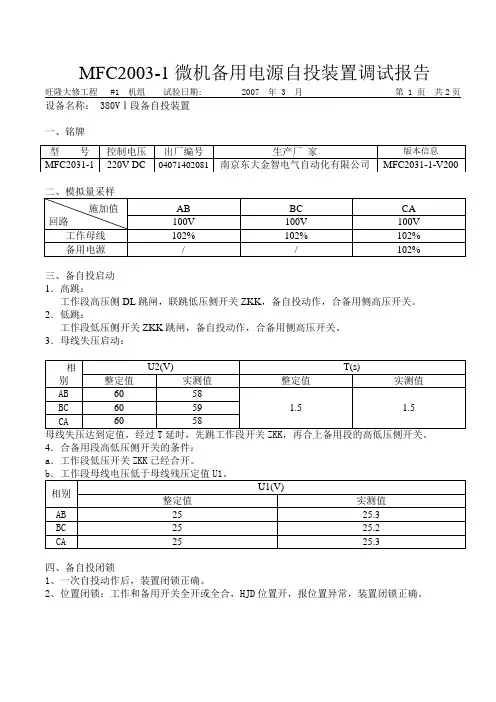
旺隆大修工程 #1 机组试验日期: 2007 年 3 月第 1 页共2页设备名称: 380VⅠ段备自投装置一、铭牌三、备自投启动1.高跳:工作段高压侧DL跳闸,联跳低压侧开关ZKK,备自投动作,合备用侧高压开关。
2.低跳:工作段低压侧开关ZKK跳闸,备自投动作,合备用侧高压开关。
3.母线失压启动:4.合备用段高低压侧开关的条件:a.工作段低压开关ZKK已经合开。
四、备自投闭锁1、一次自投动作后,装置闭锁正确。
2、位置闭锁:工作和备用开关全开或全合,HJD位置开,报位置异常,装置闭锁正确。
4、PT断线闭锁正确。
5、外部接点闭锁正确。
五、开关量输入检查:正确。
六、跳合闸出口和信号出口检查:正确。
七、屏幕显示及指示灯显示:正确。
八、试验传动:1、高跳正确2、低跳正确3、母线无压正确九、操作回路绝缘:18MΩ。
十、试验结论:设备合格。
十一、试验仪器:昂立——备用8G 继电保护测试仪精度:0.2试验人员:试验负责人:旺隆大修工程 #1 机组试验日期: 2007 年 3 月第 1 页共2页设备名称:除尘母线Ⅰ段备自投装置一、铭牌三、备自投启动1.高跳:工作段高压侧DL跳闸,联跳低压侧开关ZKK,备自投动作,合备用侧高压开关。
2.低跳:工作段低压侧开关ZKK跳闸,备自投动作,合备用侧高压开关。
3.母线失压启动:4.合备用段高低压侧开关的条件:a.工作段低压开关ZKK已经合开。
四、备自投闭锁1、一次自投动作后,装置闭锁正确。
2、位置闭锁:工作和备用开关全开或全合,HJD位置开,报位置异常,装置闭锁正确。
4、PT断线闭锁正确。
5、外部接点闭锁正确。
五、开关量输入检查:正确。
六、跳合闸出口和信号出口检查:正确。
七、屏幕显示及指示灯显示:正确。
八、试验传动:1、高跳正确2、低跳3、母线无压九、操作回路绝缘:18MΩ。
十、试验结论:设备合格。
十一、试验仪器:昂立——备用8G 继电保护测试仪精度:0.2试验人员:试验负责人:旺隆大修工程 #1 机组试验日期: 2007 年 3 月第 1 页共2页设备名称:除灰母线备自投装置一、铭牌三、备自投启动1.高跳:工作段高压侧DL跳闸,联跳低压侧开关ZKK,备自投动作,合备用侧高压开关。

CR-21B变电站自动化系统备用电源自投单元说明书西安开元电力自动化有限公司备用电源自投单元技术说明概述CR—21BZT型微机备用电源自投单元适用于电力系统35KV、110KV变电站。
装置既可单独使用,也可与变电站自动化配套使用。
能自动完成各种类型的备用电源自投,还具有测量、控制功能。
工作原理交流采样频率为600H Z,各个电量用差分和付氏算法求得,通过数字滤波,显示各电量,作出保护逻辑判断,驱动或闭锁单元上的出口继电器,同时有利于消除模拟通道的零漂,同时具有较高的精度和可靠性。
单元具有完善的防跳回路及断路器控制电路。
可靠的自保持回路,保证了开关拒动时不使继电器损坏。
产品功能1、备自投功能1.1 投入原则:A:一主一备方式:当正常供电,线路电压消失,且无电流,确认不是PT断线造成的,经延时后,检查备用电源是否正常,备用进线断路器是否在分位置,分段是否在合位置。
跳开正常状态下供电电源的断路器,并确认已经跳开,再合上备用电源断路器。
B:进线变压器组方式:首先检查工作电压是否消失,确认不是PT断线造成的,经延时后,检查另一回路是否正常,分段是否在分位置,跳开本回路进线断路器,合上分段断路器。
PT断线闭锁判据电压降低时,进线电流互感器电流不消失为PT断线。
电压仅一相或两相降低,判为故障或PT 断线,通过延时躲开故障。
1.2 测量功能电流: Ia ,Ib,Ic电压:输入U A,U B,U C,经计算得到U A,U B,U C,U N,U AB,U BC,U CA及3U0。
以及:P,Q,COSΦ各有关断路器的分合状态。
开关量采集通过光电隔离,抗干扰能力强。
1.3 控制功能可手合(分)、遥合(分)本进线断路器。
2.每个备投单元只完成线路的测量,控制及备投逻辑功能,系统的备投功能需在每条进线装一个备投单元,并要与分段单元通过联动完成,单元之间的联动通过220V开入开出完成本系统还可完成主变低压侧备投功能,并且主变本体保护闭锁备投。
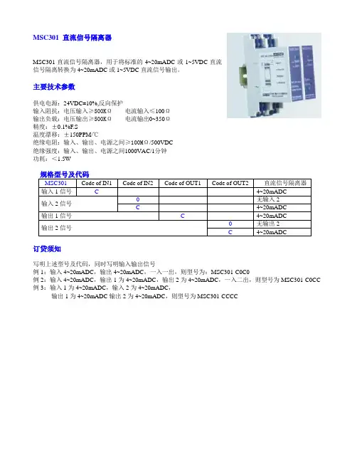
MSC301直流信号隔离器,用于将标准的4~20mADC或1~5VDC直流
信号隔离转换为4~20mADC或1~5VDC直流信号输出。
主要技术参数
供电电源:24VDC±10%,反向保护
输入阻抗:电压输入≥500KΩ电流输入≤100Ω
输出负载:电压输出≥500KΩ电流输出0~350Ω
精度:±0.1%F.S
温度漂移:±150PPM/℃
绝缘电阻:输入、输出、电源之间≥100MΩ/500VDC
绝缘强度:输入、输出、电源之间1000VAC/1分钟
功耗:<1.5W
订贷须知
写明上述型号及代码,同时写明输入输出信号
例1:输入4~20mADC,输出4~20mADC,一入一出,则型号为:MSC301-C0C0
例2:输入4~20mADC,输出1为4~20mADC,输出2为4~20mADC,一入二出,则型号为MSC301-C0CC 例3:输入1为4~20mADC,输入2为4~20mADC,
输出1为4~20mADC输出2为4~20mADC,则型号为MSC301-CCCC
23
+-
10
7
+
-
+-powe r su ppl y
24VDC DCS AI
MSC301-C0C011
12
23
+-
10
7
+-
+-powe r su ppl y
24VDC
DCS AI-1MSC301-C0CC
11
12
Curren t S ou rce
89
+-DCS AI-2
Curren t S ou rce
Curren t S o
Curren t S o。

MFC2031-1型微机备用电源自投装置说明书东大金智软件股份有限公司南京东大金智电气自动化有限公司二00一年八月1目录1.概述 (1)2.主要技术指标 (1)3.原理简介 (2)4.装置软硬件简介 (3)5.主要功能 (6)6.液晶显示菜单说明 (7)7.运行说明 (10)8.设计说明 (10)1MFC2031-1型微机备用电源自投装置说明书1. 概述MFC2031系列微机备用电源自投装置是在MFC2000系列微机厂用电快速切换装置的基础上研制而成的,在硬件和软件上,采用了MFC2000快切装置的成熟技术,结合备自投装置本身的技术要求,进行了相应的调整补充。
装置采用INTEL16位单片机80C196KC ,全中文液晶显示菜单,性能优越,用户界面友好。
装置具有完善的软硬件抗干扰措施,并具备485及RS232通信接口。
MFC2031-1型微机厂用低压备自投装置适用于发电厂低压厂用系统1个备用段(或备用进线)备1个工作段的场合,也可用于其它1备1场合。
2. 主要技术指标2.1装置直流电源a . 额定电压 DC220V 或110Vb . 允许偏差 -20~+15%c . 纹波系数 不大于5% 2.2额定参数a . 交流电压:100V 或57.7Vb . 频率:50HZ2.3功率消耗a . 交流电压回路:当电压为额定值时,每相不大于1V Ab . 直流电源回路:当工作正常时,不大于30W当自投动作时,不大于50W2.4输出接点容量a . 跳合闸接点容量:DC220V ,5A (接通)b . 信号接点容量:DC220V ,50W 2.5电压测量准确度a . 刻度误差:不大于±1%b . 温度变差:在工作环境温度下,不大于±1%c . 综合误差:不大于±2% 2.6工作大气条件2a . 环境温度:-10~+50℃b . 相对湿度:5~95%c . 大气压力:86~106Kpa 2.7 过载能力 a. 交流电压回路:1.5倍额定电压,连续工作。


MFC5103A工业企业电源快速切换装置说明书金智科技股份有限公司前言非常感谢您选用江苏金智科技股份有限公司(简称金智科技,股票代码002090)生产的MFC5103A工业企业电源快速切换装置。
本手册是该型装置的说明书,期望它能为您的工作带来帮助。
本说明书仅供设计选型参考,与实际产品可能存在细微差别,因此不建议作为工程设计依据。
建议工程设计时向我公司设计人员索取相关设计图纸。
如需相关产品、服务和支持的更多信息,请访问金智科技网站/。
本公司有权对本说明书的内容进行定期变更,恕不另行通知。
变更内容将会补充到新版本的说明书中。
如您需要更新版本,敬请与我公司联系。
_____________________________________________________________版权所有,请勿翻印、复印。
说明书版本号:V MFC5103A -201001-25-T 印刷时间:2010年4月目录1. 装置概述 (1)2. 装置特点及主要技术指标 (2)2.1. 装置特点 (2)2.2. 主要技术指标 (3)3. 接线方式 (5)3.1. 单母分段方式 (5)3.2. 单母方式 (6)4. 切换功能 (6)4.1. 起动方式 (6)4.2. 切换方式 (9)4.3. 实现方式 (10)4.4. 切换功能图 (10)5. 装置运行告警 (11)5.1. 进线/母线TV断线 (11)5.2. 方向过流闭锁 (12)6. 分段方式下切换逻辑充电及放电 (12)6.1. 开关1到3切换 (12)6.2. 开关2到3切换 (13)6.3. 开关1到2切换 (14)6.4. 开关2到1切换 (15)6.5. 开关3到1切换 (15)6.6. 开关3到2切换 (16)7. 单母方式下切换逻辑充电及放电 (17)7.1. 开关1到2切换 (17)7.2. 开关2到1切换 (18)8. 其它功能 (18)8.1. 保护功能 (18)8.2. 联切功能 (20)8.3. 去耦合功能 (20)9. 定值参数 (20)10. 背板端子说明 (24)11. 外形及安装尺寸 (27)12. 使用说明 (28)12.1. 面板布置图 (28)12.2. 液晶显示说明 (28)12.3. 命令菜单使用说明 (30)12.4. 装置运行说明 (33)12.5. 事故分析注意事项 (34)附录:快速切换原理 (34)F1.1快速切换 (34)F1.2同期捕捉切换 (37)F1.3残压切换 (38)F1.4长延时切换 (39)1.装置概述石化、冶金等大中型工业企业,由于外部电网或内部供电网络故障或异常的原因,造成非正常停电、电压大幅波动或短时断电(俗称“晃电”)的情况屡见不鲜。
电气培训教材MFC2031-1微机备自投装置简介我厂备自投采用MFC2031-1系列的微机备用电源自投装置,该装置采用INTEL16位单片机80C196KC,全中文液晶显示菜单,其通讯接口为485及RS232,它适合于低压厂用电系统一个备用段备一个工作段的运行方式。
1原理介绍:正常运行时,工作变的高、低压侧开关在合位。
而在备用电源在热备方式下高压侧的开关为合位,低压侧开关为分位;在备用电源冷备状况下,高、低压侧同时为分位。
当备用电源自投时,先跳工作电源的低压侧开关,确认工作电源低压侧开关跳开后,依次合上备用电源的高、低压侧开关。
2备自投装置就绪状态介绍:2.1当满足下列条件时,10秒后自动进入就绪状态:1)工作电源的高、低压侧开关在合位;2)380V母线PT电压正常,备用电源6000V母线PT电压正常。
2.2备自投的启动原则:1)当工作电源高压侧电源开关跳闸,备自投装置启动,先判断工作电源低压侧开关联跳,依次合上备用电源高、低压侧电源开关。
2)当工作电源低压侧电源开关跳闸,备自投装置启动,先判断工作电源低压侧开关跳开,依次合上备用电源高、低压侧电源开关。
3)当380V母线三相失压,(电压低于整定值)经过延时后,备自投启动,先跳工作电源的低压侧开关,依次合上备用电源高压侧开关和低压侧电源。
2.3备自投闭锁投入的条件:1)刚完成一次备自投动作后。
会发出“备自投动作”、“备自投闭锁”信号。
2)工作电源高、低压侧开关和备用电源的高、低压开关均合上或均断开时,备自投无法进行自投,会发“备自投闭锁”、“开关异常”信号。
3)备自投装置启动后,当发出跳工作电源低压侧开关命令,约0.6秒后如工作电源低压侧开关的辅助接点断开信号未返回时,装置认为工作电源低压侧开关拒动,为了防止备自投投入出现故障,而不发依次合备用电源高、低压侧开关。
并且发“备自投闭锁”及“开位异常”信号。
4)当用母线PT检测到无压时,即备用电源母线电压低于设定值,将不进行备自投,并且发“备自投闭锁”、“备用电源无压”。
NDB310数字式备用电源自投装置 技术说明书 南京南自电网控制技术有限责任公司 * 2006年6月第三次印刷。
* 本说明书内容适用于V3.XX版本,如有修改,恕不另行通知,请访问互联网:http://www.nps-naef.com下载最新版本。
目录1 装置简介 (1)1.1 适用范围 (1)1.2 产品特点 (1)2 技术参数 (3)2.1 环境参数 (3)2.2 额定电气参数 (3)2.3 主要技术指标 (3)2.4 通信接口 (3)2.5 输出接点容量 (4)2.6 电磁兼容 (4)2.7 机械结构 (4)3 装置原理说明 (7)3.1 装置资源配置 (7)3.2 可编程自投逻辑功能说明 (7)3.3 装置辅助功能 (8)3.4 定值清单及说明 (9)3.5 NDB310数字式备用电源自投装置背端子图 (10)4 典型工程配置说明 (11)4.1 单母线分段(一主一备)接线 (11)4.2 双母线(一主一备)接线 (15)4.3 单母线分段带旁路(一主一备)接线 (19)4.4 单母线分段带旁路(两主一备)接线 (24)4.5 单母线分段带旁路(两主两备)接线 (35)4.6 10kV三主变接线一 (57)4.7 10kV三主变接线二 (62)4.8 10kV两主变接线 (66)5 装置使用说明 (72)5.1 按键功能介绍 (72)5.2 面板布置说明 (73)5.3 命令菜单使用说明 (73)1 装置简介 1.1适用范围 备用电源的一次接线形式种类较多,备自投逻辑有较大差别。
常规的备自投装置常常需要根据具体工程的应用要求修改软件,增加了工程应用的难度,且影响了备自投设备的可靠性。
为更广泛地适用于各种现场要求,在NDB310数字式备用电源自投装置中,通过NDV300调试软件对备自投逻辑编程,再将编程结果下装到装置,实现备自投功能。
可以适用于220kV及以下电压等级变电站及厂用电部分的各种接线方式的备用电源自投。
Our Improvement upon Your SupportNote: Please make sure to examine the following items before power-on:* Reliable grounding of device enclosure.* Power supply of the device is AC or DC and 240V.(If 110V power supply is required, it shall be indicated during ordering.)* Default of device input is passive contact input.(If active contact input of DC 240V is required, it shall be indicated during ordering.)* Default of the device is without anti-bouncer function(If product with anti-trip function is required, it shall be indicated during ordering.)* Correct polarity of current input as well as correct phase sequence of voltage input* During on-site debugging, power-on time of high current shall not be too long (For this device, continuous running is available when current in the AC current circuit is twice of the rated current, 10s running is allowable under ten times of the rated current and 1s running is allowable under 40 times of the rated current.), so as to avoid unnecessary damage.1概述YZ201/301系列综合微机保护装置是采用计算机技术、电力自动化技术、通信技术等多种高新技术的新型电器产品。
Unmatched performance, safety and serviceabilityProven performance and reliability•Automatic bypass switch provides operational redundancy and quickly restores power to criticalloads when the ATS has been isolated for test or removed for service•Automatic, non-automatic and manual A operation modes provide multiple methods of transferring the load between power sources•UL 1008 listed short-circuit and short-time B withstand closing current ratings maximize system reliability •Tethered remote controlallows an operator to initiate a non-automatic transfer outside the arc flash boundaryEnhanced safety•Unique three-door,compartmentalized design provides steel barriers protecting workers from energized components •All doors open/closeindependently eliminating unnecessary exposure to adjacent compartments •Integral safety interlocks automatically open the main contacts prior to the ATS or automatic bypass switch being isolated for test or removed for service•Rear shutters B automatically close to isolate bus stabs when the ATS or automatic bypass switch is being racked outEaton has enhanced its comprehensive portfolio of UL T 1008 listed bypass isolation ATS solutions with power contactor type designs specifically engineered for applications between 100 and 3000 A.Our bypass isolation ATSs are not only simple to operate, but also available in a broad selection of configurations and features to meet a wide variety of application requirements.When coupled with our extensive custom engineering capabilities, Eaton’s innovative three-door bypass isolation ATS design, robust compartmentalized construction, and redundant automatic operation set the standard for concurrent serviceability, worker safety, and optimizing critical system uptime.Improved serviceability•Innovative three-door design eliminates the need to schedule shutdowns for routine test, inspection or maintenance•Maintenance isolationswitch (MIS) permits service personnel to electricallyisolate control compartment elements and minimize shock hazard prior to beginning work —without disruption to critical loads•Control compartment door and adjoining electrical panel slide forward from the enclosure to provide easy access to wiring and components•Dual drawout design allows the ATS or automatic bypass switch to be disconnected from the electrical bus and isolated in cell for regular testing as prescribed by code (NFPA T 70, 99, 110)•Testing of isolated switch can be performed while ATS or automatic bypass switch is in automatic or non-automatic mode of operationSimplified installation and integration•Field-configurable terminals allow cable ingress at top/ bottom for power source and load connections•Internal floor-mount anchors minimize footprint andfacilitate efficient integration into an equipment lineup •Seismic certified to OSHPD, CBC, IBC and UBC•Front and rear access availableFeatures and benefitsA Manual operation (unloaded) provided for all product configurations; manual operation (under load)available for select catalog configurations.B Feature/rating available for select catalog configurations.Bypass isolationContactor type, 100–3000 AOpen/closed transitionDesign featuresDual automatic technologyEaton’s unique design includes an automatic bypass switch and an ATS within a single assembly to provide redundant automatic operation and uninterrupted power to critical loads.Optimize reliability and maximize uptimeThe automatic bypass switch and ATS can be racked out and isolated in cell for regular testing to ensure the entire bypass isolation transfer switch is maintained in proper operating condition.Facilitate scheduled maintenance The automatic bypass switch or ATS can be withdrawn for visual inspection andcompletely removed for bench testing without impacting automatic operation.Enhance worker safetyThe upper and lower doors can be operated independently, maintaining electrical isolation of the energized compartment.T esting… it’s as easy as 1-2-3 A three-step operator interface helps simplify testing procedures of the automatic bypass switch or ATS when racked out to the isolated position.Safe and serviceableEngineered for safety, athree-door compartmentalized construction coupled with an MIS allow personnel to perform maintenance on the bypass isolation transfer switch while energized.To mitigate shock hazard, the MIS can be placed in the maintenance position prior to opening the door, electrically isolating elements of the control compartment from system and control voltage.Once isolated, the control compartment door can beopened and adjoining electrical panel slid forward, allowing a technician to safely inspect, troubleshoot and replace electrical components.Upon completion, the door is closed and MIS returned to the normal operation position.Multiple operation modes Local operation is possible in the following modes:• Automatic • Non-automatic •Manual AIn Automatic mode, the transfer switch is self-acting, and atransfer is automatically initiated by the intelligent controller logic.In Non-Automatic mode, a transfer is initiated by theoperator using a door-mounted selector switch or an optional tethered remote control.In Manual mode, a transfer is initiated by the operator using controls mounted directly on the automatic bypass switch or ATS.Alternatively, a transfer can be initiated remotely via an HMi remote annunciator controller or network communication.Automatic bypass switch With the upper door open, operators can draw out the automatic bypass switch for inspection or maintenance.With the upper door closed, operators can rack out, isolate and test the automatic bypass switch in cell.Automatic transfer switch With the lower door open,operators can draw out the ATS for inspection or maintenance. With the lower door closed, operators can rack out, isolate and test the ATS in cell.Control compartment door and adjoining electrical panel slide forward.MIS provides ability to electrically isolate control compartment elements prior to start of maintenance.Safe, easy and spacious access to wiring and components.Electrical load remains connected to power during maintenance procedures.Featuring simplified testing procedures for the ATS and automatic bypass switchT ethered remote control for non-automatic operationA Manual operation (unloaded) provided for all product configurations;manual operation (under load) available for select catalog configurations.2EATON Bypass isolation automatic transfer switches (ATS)Product selectionCatalog numbering systemTechnical specificationsA Check with your local Eaton sales representative for NEMA 12 and NEMA 4X enclosure specifications. NEMA 3R stainless steel available upon request.B Dimensions in inches (mm) and weight in lb (kg). Data is approximate, subject to change, and representative of a typical product configuration.Please reference product outline drawing(s) for latest information. Custom-engineered enclosure options available upon request.A Standard mechanical lugs are UL listed, solderless screw-type Cu/Al. Number of conductors and size range shown is per pole and representative of typical product configuration.B Two-hole compression lug or bus connect provisions available upon request. Please contact your local Eaton sales representative for more details.C Only applies to wye system configuration with solid neutral. For four-pole (switched neutral) configurations, the number and size of conductors supported will mimic the Normal,Emergency and Load terminal information shown.ote: N Some catalog number combinations may not be available. For additional information, please contact your local Eaton sales representative.3EATON Bypass isolation automatic transfer switches (ATS)Eaton is a registered trademark.All other trademarks are property of their respective owners.Eaton1000 Eaton Boulevard Cleveland, OH 44122United States © 2020 EatonAll Rights Reserved Printed in USAPublication No. PA140014EN / Z24636December 2020ATC-900—intelligent controlEaton’s ATC-900 controller brings ease of use, adaptability, supervisory and programming capabilities to mission-criticalapplications. The 4.3-inch color TFT display provides simple arrow keys for quick screen navigation and easy viewing of event logs as well as recorded time-stamped events. Field configuration ofprogrammable I/O allows user adaptability to special requirements.A Modbus TCP/IP option requires use of Modbus RTU port.HM i remote annunciator controllerEvolving arc flash regulations and requirements for personal protective equipment are driving more and more end users toward the use of remote monitoring and control devices. Eaton’s HM i remote annunciator controller offers a simple and cost-effective means of managing up to eight ATSs via serial or ethernet communication.Remote annunciator controllerCustom-order engineeringIn many cases, standard products can be custom-order engineered to meet unique application needs. For additional information, pleasecontact your local Eaton sales representative./bypassATSFollow us on social media to get thelatest product and support information.。
380V厂用电快切装置的应用石峰【摘要】针对旺隆电厂380 V厂用电系统中MFC2031型微机型备用电源自动投入(以下简称备自投)装置切换慢,无法满足负荷对母线电压要求及380 V厂用电倒闸操作十分繁琐的问题,对380V厂用2W(母线)备自投装置进行改造,成功地以MFC5103型工业企业电源快速切换装置替代MFC2031型微机型备自投装置,大大缩短了备用电源切换过程,维持母线电压在一个较高水平,满足了各类重要负荷对母线电压的要求,提高了机组运行的可靠性.【期刊名称】《广东电力》【年(卷),期】2011(024)007【总页数】4页(P70-72,76)【关键词】厂用电系统;备用电源;自动投入装置;快速切换【作者】石峰【作者单位】广州市旺隆热电有限公司,广东广州511340【正文语种】中文【中图分类】TM762.1旺隆电厂380 V厂用电系统原备用电源自动投入装置使用的是MFC2031型微机型备用电源自动投入(以下简称备自投)装置。
该装置能实现工作电源高、低压断路器跳闸投入备用电源及母线失压投入备用电源等功能,满足备用电源可靠投入的要求,但因为装置切换慢,在备用电源合闸条件上,采用延时和无压判据等导致备自投投入动作时间过长,长达1~2 s,无法维持380 V厂用电压在一个较高的水平,难以满足重要电动机、变频器、交流接触器等设备的正常工作要求[1-2]。
为此,以380 V厂用2 W(母线)为试点,采用MFC5103型工业企业电源快速切换装置替代原有的MFC2031型微机型备自投装置,实现380 V厂用电系统中电源的快速切换,提高供电可靠性。
1 电源快速切换原理广州旺隆电厂供电系统如图1所示。
图1 供电系统示意图图1中,正常运行时,断路器QF1和QF2合闸,断路器QF3分闸,线路1和线路2互为备用。
当线路1发生故障后,必须先跳开QF1后再合上QF3;当线路2发生故障后,必须先跳开QF2后再合上QF3。
2031M型压力模块使用说明书天津市国力电子有限公司(96)量制津字00000321号目录1、概述 (1)2、主要技术指标 (1)3、结构特征 (2)4、使用与维护 (2)5、校准点 (7)6、附件 (7)1、概述2031M型压力模块是与TPO-2031型数字式多功能校准仪配合使用,用来进行压力校验和检测配套装置。
本模块采用进口传感器,铝合金外壳,具有精度高、可靠性强、体积小、重量轻、携带方便、与主表连接简单等特点。
1.1 环境温度:0~40︒C1.2 相对湿度:+40︒C 80%RH1.3 大气压力:86~106kPa1.4 压力介质:非腐蚀性气体或液体1.5 压力接口尺寸:Ф4mm自锁螺口(1.0MPa以下,可外接Ф4⨯6mm塑料管)或M20⨯1.5mm外螺纹(1.0MPa 以上)1.6 与主机连接:电缆线连接,直接插入主机压力模块接口插孔1.7 校准周期:一年1.8 外型尺寸:75⨯45⨯80(mm)1.9 重量:约200g2、主要技术指标(23︒C±5︒C):3、结构特征前面板示意图:型号编号量程精度日期备注天津市国力电子有限公司与主机连线接口后面板示意图:Z E R O P R E S S压力调零旋钮压力输入端口注:当压力量程大于1MPa时,压力传感装置从“PRESS”处以外接引线的方式接出,这样便于您与压力输入(压力源)连接。
4、使用与维护注意事项:-2-*绝对禁止将大于本说明书中规定的压力加到压力信号输入端,否则将会损坏压力测量功能,这将给您造成极大的损失。
*插接或换装模块时一定要确认主机(TPO-2031)处于关机状态,否则将可能损坏本模块或主机。
*严禁自行打开此模块,如需打开调整校准时,应首先与我单位联系,以确定打开模块时需注意的事项。
4.1 压力测量使用压力测量时,按下图将本模块与主机(TPO-2031)连接:模块前面板T P O -2031后面板将要测量的压力输入到后面板“PRESS ”压力输入端口 (或外接传感器上)。