步进电机PC-SMC使用手册
- 格式:pdf
- 大小:1.08 MB
- 文档页数:34

步进电机控制器说明书本文档旨在提供步进电机控制器的详细说明,包括其功能、使用方法和技术参数等内容。
以下是各章节的具体细化:1. 引言1.1 背景介绍1.2 目的与范围2. 控制器概述2.1 功能特点- 步进电机驱动能力强大,适用于多种应用场景。
- 支持多种通信接口(如RS485、CAN)以及常见编程语言(如C++、Python)。
- 提供丰富而灵活的运动控制模式。
3. 硬件配置要求3.1最低硬件需求CPU:Intel Core i5或更高版本;内存:8GB RAM 或以上;存储空间:100GB 可用磁盘空间;3.2推荐硬件配置CPU: Intel Core i7-9700K;内存:16 GB DDR4;显卡:NVIDIA GeForce RTX2060 Super;4.安装指南4-1安装前准备工作a) 操作系统选择:Windows操作系统推荐Windows10, Linux操作系統建议Ubuntu18+.b) 软件:访问官方网站最新版本的步进电机控制器软件。
4-2安装过程a) 运行安装程序,按照提示完成安装;b) 配置相关参数以适应实际需求。
5. 使用方法5.1 控制器连接与通信设置- 描述如何将控制器与计算机或其他设备进行连接,并配置相应的通信接口和参数。
5.2 步进电机驱动设置- 解释如何使用控制器来驱动步进电机,并提供示例代码和操作指南。
5.3 运动控制模式选择及调整-介绍不同运动模式(位置、速度等)的特点和用法,并说明如何根据需要进行调整。
6.技术规格6-1输入/输出端口提供输入/输出引脚定义表;描述各个引脚功能及其对应编号。
6—2总线协议支持列出所支持总线协议名称;指明每种总线协议在本系统中具体作用。
7.故障排除7_1常见问题解答常见问题并给予解决方案;8.附件:请参考附件文件。
法律名词及注释:1. 步进电机:一种将脉冲信号转换为角位移的执行器,通常由定子和转子组成。
2. 控制器:用于控制步进电机运动的设备或系统。

MODULE FOR STEPPER MOTORSTRINAMIC Motion Control GmbH & Co. KGHamburg, GermanyHardware Version V1.4HARDWARE MANUAL+ +TMCM-1021++U NIQUE F EATURES :Table of Contents1Features (3)2Order Codes (5)3Mechanical and Electrical Interfacing (6)3.1Size of Board (6)3.1.1Board mounting considerations (6)3.2Connectors (7)3.2.1Power, Communication and I/O Connector (8)3.2.2Motor Connector (13)4Motor driver current (14)5Reset to Factory Defaults (16)6On-board LED (16)7Operational Ratings (17)8Functional Description (19)9Life Support Policy (20)10Revision History (21)10.1Document Revision (21)10.2Hardware Revisions (21)11References (22)1FeaturesThe TMCM-1021 is a single axis controller/driver module for 2-phase bipolar stepper motors with state of the art feature set. It is highly integrated, offers a convenient handling and can be used in many decentralized applications. The module can be mounted on the back of NEMA11 (28mm flange size) and has been designed for coil currents up to 0.7A RMS (low current range, programmable) or 1.4A RMS (high current range, programmable, new additional range since hardware version 1.4) and 24V DC supply voltage. With its high energy efficiency from TRINAMIC’s coolStep™ technology cost for power consumption is kept down. The TMCL™ firmware supports remote control (direct mode) and standalone operation (with TMCL program being executed on the TMCM-1021 itself).M AIN C HARACTERISTICSHighlights-Motion profile calculation in real-time-On the fly alteration of motor parameters (e.g. position, velocity, acceleration)-High performance microcontroller for overall system control and serial communication protocol handling -For position movement applications, where larger motors do not fit and higher torques are not required Bipolar stepper motor driver-Up to 256 microsteps per full step-High-efficient operation, low power dissipation-Dynamic current control-Integrated protection-stallGuard2 feature for stall detection-coolStep feature for reduced power consumption and heat dissipationEncoder-sensOstep magnetic encoder (max. 1024 increments per rotation) e.g. for step-loss detection under all operating conditions and positioning supervisionInterfaces-Up to 4 multi-purpose inputs (2 shared with general purpose outputs)- 2 general purpose outputs-RS485 2-wire communication interfaceSoftware-TMCL: s tandalone operation or remote controlled operation,program memory (non volatile) for up to 876 TMCL commands, andPC-based application development software TMCL-IDE available for free.Electrical and mechanical data-Supply voltage: +24V DC nominal (9… 28V DC max.)-Motor current: up to 0.7A RMS (low current range, programmable) or 1.4A RMS (high current range, programmable, new additional range since hardware version 1.4)Please refer to separate TMCL Firmware Manual, also.TRINAMIC S U NIQUE F EATURES – E ASY TO U SE WITH TMCLstallGuard2™ stallGuard2 is a high-precision sensorless load measurement using the back EMF on the coils.It can be used for stall detection as well as other uses at loads below those which stall the motor. The stallGuard2 measurement value changes linearly over a wide range of load, velocity, and current settings. At maximum motor load, the value goes to zero or near to zero. This is the most energy-efficient point of operation for the motor.Load [Nm]stallGuard2Initial stallGuard2 (SG) value: 100%Max. loadstallGuard2 (SG) value: 0Maximum load reached. Motor close to stall. Motor stallsFigure 1.1 stallGuard2 load measurement SG as a function of loadcoolStep ™coolStep is a load-adaptive automatic current scaling based on the load measurement via stallGuard2 adapting the required current to the load. Energy consumption can be reduced by as much as 75%. coolStep allows substantial energy savings, especially for motors which see varying loads or operate at a high duty cycle. Because a stepper motor application needs to work with a torque reserve of 30% to 50%, even a constant-load application allows significant energy savings because coolStep automatically enables torque reserve when required. Reducing power consumption keeps the system cooler, increases motor life, and allows reducing cost.00,10,20,30,40,50,60,70,80,9050100150200250300350EfficiencyVelocity [RPM]Efficiency with coolStepEfficiency with 50% torque reserveFigure 1.2 Energy efficiency example with coolStep2Order CodesTable 2.1 Order codesA cable loom set is available for this module:Table 2.2 Cable loom order code3Mechanical and Electrical Interfacing3.1Size of BoardThe board with the controller/driver electronics has an overall size of 28mm x 28mm in order to fit on the back side of a NEMA11 (28mm flange size) stepper motor. The printed circuit board outline is marked green in the following figure:PCB outlineR 2.5mmFigure 3.1 Board dimensions and position of mounting holesMaximum board height (without mating connectors and cable looms) is about 10mm (approx. 6mm above printed circuit board level).3.1.1Board mounting considerationsThe board offers two mounting holes for M2.5 screws (both holes with 2.6mm diameter). Both mounting holes are isolated. Nevertheless, it is highly recommended to electrically connect any metal screws used for mounting to supply ground (either directly or via resistor) in order to prevent any electrostatic discharge (ESD) across the isolation barrier. This is especially recommended in case the board is mounted to the backside of a motor.Since hardware version 1.4 a second high current range for motor currents up-to 1.4A RMS is available. This makes it possible to support NEMA11 motors with typical standard coil currents up-to 0.7A RMS using the low current range and with the same hardware also NEMA17 bipolar stepper motors with coil currents up-to 1.4A RMS using the high current range.Example for setup with TMCM-1021_V14 mounted to back side of NEMA17 motor (with sensOstep™ encoder): Figure 3.2: TMCM-1021 V14 mounted to back side of NEMA17 bipolar stepper motor3.2 ConnectorsThe TMCM-1021 has two connectors, an 8-pin power, communication and I/O (input/output) connector and a 4-pin motor connector (used to connect the attached motor).MotorPower / communication / I/Os1814Figure 3.3 TMCM-1021 connectorsOverview of connector and mating connector types:Table 3.1 Connectors and mating connectors, contacts and applicable wire3.2.1Power, Communication and I/O ConnectorAn 8-pin, 2mm pitch single row connector is used for power supply, RS485 serial communication and additional multi-purpose inputs and outputs.Table 3.2 8pin power, communication and I/O connector3.2.1.1 Power supplyFor proper operation care has to be taken with regard to power supply concept and design. Due to space restrictions the TMCM-1021 includes just about 20µF/35V (V1.2) resp. 30µF/35V (V1.4) of supply filter capacitors. These are ceramic capacitors which have been selected for high reliability and long life time. The module includes a 24V suppressor diode for over-voltage protection.Please take the following measures into account in order to avoid serious damage of the device:Add external power supply capacitors!It is recommended to connect an electrolytic capacitor of significant size (e.g. 470µF/35V) to the power supply lines next to the TMCM-1021!Rule of thumb for size of electrolytic capacitor: In addition to power stabilization (buffer) and filtering this added capacitor will also reduce any power supply wires and the ceramic capacitors. In addition it will limit slew-rate of power supply voltage at the module. The low ESR of ceramic-only filter capacitors may cause stability problems with some switching power supplies.Keep the power supply voltage below the upper limit of 28V!Otherwise operating voltage is near the upper limit a regulated power supply is highly recommended. Please see also chapter 7, operating values.There is no reverse polarity protection!The transistors.3.2.1.2 RS485For remote control and communication with a host system the TMCM-1021 provides a two wire RS485 bus interface. For proper operation the following items should be taken into account when setting up an RS485 network:1. BUS STRUCTURE :The network topology should follow a bus structure as closely as possible. That is, the connection between each node and the bus itself should be as short as possible. Basically, it should be short compared to the length of the bus.termination resistor (120 Ohm)termination resistor (120 Ohm)Figure 3.4: Bus structure2. BUS TERMINATION :Especially for longer busses and/or multiple nodes connected to the bus and/or high communication speeds, the bus should be properly terminated at both ends. The TMCM-1021 does not integrate any termination resistor. Therefore, 120 Ohm termination resistors at both ends of the bus have to be added externally.TMCM-1021 V1.4 Hardware Manual (Rev. 1.04 / 2018-JAN-22) 103. NUMBER OF NODES :The RS485 electrical interface standard (EIA-485) allows up to 32 nodes to be connected to a single bus. The bus transceivers used on the TMCM-1021 units (hardware V1.2: SN65HVD3082ED, since hardware V1.4: SN65HVD1781D) have a significantly reduced bus load and allow a maximum of 255 units to be connected to a single RS485 bus using TMCL firmware. Please note: usually it cannot be expected to get reliable communication with the maximum number of nodes connected to one bus and maximum supported communication speed at the same time. Instead, a compromise has to be found between bus cable length, communication speed and number of nodes.4. COMMUNICATION SPEED:The maximum RS485 communication speed supported by the TMCM-1021 is 115200 bit/s (FW version 1.29 with TMCM-1021 hardware version 1.2 and 1.4). Factory default is 9600 bit/s. Please see separate TMCM-1021 TMCL firmware manual for information regarding other possible communication speeds below 115200 bit/s.5. NO FLOATING BUS LINES:Avoid floating bus lines while neither the host/master nor one of the slaves along the bus line is transmitting data (all bus nodes switched to receive mode). Floating bus lines may lead to communication errors. In order to ensure valid signals on the bus it is recommended to use a resistor network connecting both bus lines to well defined logic levels.There are actually two options which can be recommended:Add resistor (Bias) network on one side of the bus, only (120R termination resistor still at both ends):termination resistor(120R)RS485- / RS485Btermination resistor (220R)RS485+ / RS485AFigure 3.5: Bus lines with resistor (Bias) network on one side, onlyOr add resistor (Bias) network at both ends of the bus (like Profibus™ termination):termination resistor (220R)RS485- / RS485BRS485+ / RS485A termination resistor (220R)Figure 3.6: Bus lines with resistor (Bias) network at both endsCertain RS485 interface converters available for PCs already include these additional resistors (e.g. USB-2-485 with bias network at one end of the bus).3.2.1.3 Digital Inputs IN_0 and IN_1The eight pin connector of the TMCM-1021 provides four general purpose inputs IN_0, IN_1, IN_2 and IN_3. The first two inputs have dedicated connector pins while the other two share pins with two general purpose outputs.All four inputs are protected using voltage resistor dividers together with limiting diodes against voltages below 0V (GND) and above +3.3V DC. Input circuit of the first two inputs IN_0 and IN_1 is shown below:IN_0,IN_1microcontroller and stepper motor driverFigure 3.7 General purpose inputs IN_0 and IN_1The two inputs have alternate functions depending on configuration in software. The following functions are available:Table 3.3 Multipurpose inputs / alternate functionsAll four inputs are connected to the on-board processor and can be used as general purpose digital inputs.Using the alternate function 1 of IN_0 and IN_1 it is possible to control the on-board stepper motor driver with the help of an external stepper motor controller using step and direction signals (Please see separate TMCL firmware manual / axis parameter 254 for more details how to enable this mode). For the step anddirection signals the signal levels are the same as for the general purpose digital inputs. Please note that the low-pass filter (for noise rejection) at the inputs offers a bandwidth of 16kHz (-3dB).IN_3 can be used as analog input, also. A 12bit analog to digital converter integrated in the microcontroller will convert any analog input voltage between 0 and +6.6V to a digital value between 0 and 4095 then.3.2.1.4Inputs IN_2, IN_3, Digital Outputs OUT_0, OUT_1The eight pin connector of the TMCM-1021 provides two general purpose outputs. These two outputs are open-drain outputs and can sink up to 100mA each. Both outputs OUT_0 and OUT_1 share pins with two of the four inputs (IN_2 resp. IN_3).The inputs are protected using voltage resistor dividers together with limiting diodes against voltages below 0V (GND) and above +3.3V DC. The circuit of the two outputs and the two inputs connected in parallel to the inputs is shown below:OUT_0 / IN_2OUT_1 / IN_3microcontrollerFigure 3.8 General purpose outputs OUT_0, OUT_1 and inputs IN_2, IN_3 connected in parallelThe outputs of the N-channel MOSFET transistors (Open-Drain) are connected to freewheeling diodes each for protection against voltage spikes especially from inductive loads (relais etc.). Please take into account the 20k (2x 10k in series) resistance to ground (transistor not active) of the input voltage divider (figure 4.8) when designing the external “load” circuit.Since hardware version 1.4 the gate inputs of the MOSFETs are pulled-low during power-up and while the processor might be still in reset / output pins not initialized. This way, the outputs will not briefly switch on at power-up.The two outputs OUT_0 / OUT_1 and inputs IN_2 / IN_3 have alternate functions depending on configuration in software:Table 3.4 Multipurpose outputs / inputs / alternate functionsDofreewheeling diodes of the outputs connected in parallel they will be shorted to power supply input voltage.For hardware version 1.2:supply voltage (e.g. directly to any power supply voltage). As the output transistors connected in parallel might briefly switch-on during power-up they might be damaged / destroyed if the current through the transistors to ground exceeds 100mA.3.2.2Motor ConnectorA 4-pin, 2mm pitch single row connector is used for connecting the four motor wires to the electronics. Table 3.4 Motor connectorDo not connect or disconnect motor during operation!Motor disconnected / connected while energized. These voltage spikes might exceed voltage limits of the driver MOSFETs and might permanently damage them. Therefore, always disconnect power supply before connecting / disconnecting the motor. For currents up-to 1.4A RMS!Setting motor current too high might lead to excessive power dissipation inside the motor, overheating current is properly set. Also with hardware version 1.2 the low current range is set as default.4Motor driver currentThe on-board stepper motor driver operates current controlled. The driver current may be programmed in software in two ranges (low current range up-to 0.7A RMS and high current range up-to 1.4A RMS) with 32 effective scaling steps in hardware for each range. Please note: the high current range is available with hardware revision V1.4, only – not with hardware revision V1.2!Explanation of different columns in table below:Motor current setting in software (TMCL)These are the values for TMCL axis parameter 6 (motor run current) and 7 (motor standby current). They are used to set the run / standby current using the following TMCL commands:SAP 6, 0, <value> // set run currentSAP 7, 0, <value> // set standby current(read-out value with GAP instead of SAP. Please see separate TMCM-1021 firmware manual for further information)Range setting in software (TMCL)This is the value for TMCL axis parameter 179 (Vsense). This value defines the current range. This value can be set using the following TMCL command:SAP 179, 0, <value> // = 0 high current range// = 1 low current rangeFor <value> either 0 (high current range) or 1 (low current range) is supported (see table) since hardware revision V1.4. For earlier hardware revisions (incl. V1.2) this parameter is set to the fixed value “1” (low current range).(read-out value with GAP instead of SAP. Please see separate TMCM-1021 firmware manual for further information)Motor currentI RMS [A]Resulting motor current based on range and motor current settingIn addition to the settings in the table the motor current may be switched off completely (free-wheeling) using axis parameter 204 (see TMCM-1021 firmware manual).5Reset to Factory DefaultsIt is possible to reset the TMCM-1021 to factory default settings without establishing a communication link. This might be helpful in case communication parameters of the preferred interface have been set to unknown values or got accidentally lost.For this procedure two pads on the bottom side of the board have to be shortened (see Figure 5.1).Please perform the following steps:1.Power supply off and USB cable disconnected2.Short two pads as marked in Figure 5.13.Power up board (power via USB is sufficient for this purpose)4.Wait until the on-board red and green LEDs start flashing fast (this might take a while)5.Power-off board (disconnect USB cable)6.Remove short between pads7.After switching on power-supply / connecting USB cable all permanent settings have been restoredto factory defaultsShort these two PADs onthe bottom of the PCBFigure 5.1 Reset to factory default settings6On-board LEDThe board offers one LED in order to indicate board status. The function of the LED is dependent on the firmware version. With standard TMCL firmware the green LED flashes slowly during operation.When there is no valid firmware programmed into the board or during firmware update the green LED is permanently on.Green LEDFigure 6.1 On-board LED7Operational RatingsThe operational ratings show the intended or the characteristic ranges and should be used as design values. In no case shall the maximum values be exceeded!Table 7.1 General operational ratings of module*) High current range available as new additional range with hardware revision V1.4 –not with hardware revision V1.2Table 7.2 Operational ratings of multi-purpose I/OsTable 7.3 Operational ratings of RS485 interface8Functional DescriptionThe TMCM-1021 is a highly integrated controller/driver module which can be controlled via RS485 interface. Communication traffic is kept low since all time critical operations (e.g. ramp calculations) are performed on board. The nominal supply voltage of the unit is 24V DC. The module is designed for both, standalone operation and direct mode. Full remote control of device with feedback is possible. The firmware of the module can be updated via the serial interface.In Figure 8.1 the main parts of the module are shown:-the microprocessor, which runs the TMCL operating system (connected to TMCL memory),-the power driver with its energy efficient coolStep feature,-the MOSFET driver stage, and-the sensOstep encoder with resolutions of 10bit (1024 steps) per revolution.9…Figure 8.1 Main parts of TMCM-1021The TMCM-1021 comes with the PC based software development environment TMCL-IDE for the Trinamic Motion Control Language (TMCL). Using predefined TMCL high level commands like move to position a rapid and fast development of motion control applications is guaranteed. Please refer to the TMCM-1021 Firmware Manual for more information about TMCL commands.9Life Support PolicyTRINAMIC Motion Control GmbH & Co. KG does not authorize or warrant any of its products for use in life support systems, without the specific written consent of TRINAMIC Motion Control GmbH & Co. KG.Life support systems are equipment intended to support or sustain life, and whose failure to perform, when properly used in accordance with instructions provided, can be reasonably expected to result in personal injury or death.© TRINAMIC Motion Control GmbH & Co. KG 2013 - 2018Information given in this data sheet is believed to be accurate and reliable. However neither responsibility is assumed for the consequences of its use nor for any infringement of patents or other rights of third parties, which may result from its use.Specifications are subject to change without notice.All trademarks used are property of their respective owners.10 Revision History 10.1Document RevisionTable 10.1 Document revision10.2Hardware Revisions*): V10, V11 and V13: prototypes only.**) V12: series product version. Is replaced with V14 series product version due to EOL (end-of-life) of the driver MOSFETs. Please see “PCN_1012_10_22_TMCM-1021.pdf” on our Web-site, alsoTable 10.2 Hardware revision11References[TMCM-1021] TMCM-1021 TMCL Firmware Manual[QSH2818-32-07-006] NEMA11 / 28mm bipolar stepper motor[QSH2818-51-07-012] NEMA11 / 28mm bipolar stepper motor[USB-2-485] USB-2-485 interface converterTRINAMIC manuals are available on .。

步进电机驱动模块说明书一、步进电机工作原理:步进电机是工业过程控制及仪表中常用的控制元件之一,例如在机械装置中可以用丝杆把角度变为直线位移,也可以用步进电机带动螺旋电位器,调节电压或电源,从而实现对执行机械的控制。
步进电机可以直接用数字信号驱动,使用非常方便。
步进电机还具有快速启停、精确步进和定位等特点,因而在数控机床、绘图仪、打印机以及光学仪器中得到广泛的应用。
步进电机是工业控制及仪表中常用的控制元件之一,例如在机械装置中可以精确控制机械装置的旋转角度、移动距离等。
步进电机可以直接用数字信号来驱动,使用非常方便。
另外步进电机还具有快速起停、精确步进和定位的特点。
步进电机实际上是一个数据/角度转换器,三相步进电机的结构原理如下图18-1所示:图18-1 三相步进电机的结构示意图从图中可以看出,电机的定子有六个等分的磁极,A、A’、B、B’、C、C’,相邻的两个磁极之间夹角为60°,相对的两个磁极组成一组(A—A’,B—B’,C—C’),当某一绕组有电流通过时,该绕组相应的两个磁极形成N极和S极,每个磁极上各有五个均分布的矩形小齿,电机的转子上有40个矩形小齿均匀地分布在圆周上,相邻两个齿之间夹角为9°。
⑴当某一相绕组通电时,对应的磁极就产生磁场,并与转子转动一定的角度,使转子和定子的齿相互对齐。
由此可见,错齿是促使步进电机旋转的原因。
例如在三相三拍控制方式中,若A相通电,B、C相都不通电,在磁场作用下使转子齿和A相的定子齿对齐,我们以此作为初始状态。
设与A相磁极中心线对齐的转子的齿为0号齿,由于B相磁极与A相磁极相差120°不是9°的整数倍(120÷9=13 2/3) ,所以此时转子齿没有与B相定子的齿对应,只是第13号小齿靠近B相磁极的中心线,与中心线相差3°,如果此时突然变为B相通电,A、C相不通电,则B相磁极迫使13号转子齿与之对齐,转子就转动3°,这样使电机转子一步。
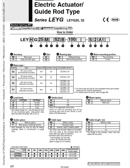
How to OrderNote) Please consult with SMC for non-standard strokes as they are produced as special orders.Refer to the applicable stroke table.T here is a limit for mounting size 32 top mounting type and 50 mm stroke or less. Refer to the dimensions.The values shown in ( ) are the lead for size 32 top mounting types. (Equivalent lead which includes the pulley ratio [1.25:1])The motor and encoder cables are included. (T he lock cable is also included when the motor with lock option is selected.) Standard cable entry direction is " Top mounting: (A) Axis side " In-line: (B) Counter axis side (Refer to page 614 for details.)Only available for size 25 and 32 sliding bearings. (Refer to “Construction” on page 290.)For auto switches, refer to pages 243 and 244.11 For motor type S2 and S6, the compatible driver part number suffixes are S1 and S5 respectively.2 For details about the driver, refer to page 598.T he length of the encoder, motor and lock cables are the same.LEY G Series LEYG LEYG25, 32847287C o u r t e s y o f C M A /F l o d y n e /H y d r a d y n e ŀ M o t i o n C o n t r o l ŀ H y d r a u l i c ŀ P n e u m a t i c ŀ E l e c t r i c a l ŀ M e c h a n i c a l ŀ (800) 426-5480 ŀ w wUse of auto switches for the guide rod type LEYG seriesInsert the auto switch from the front side with rod (plate) sticking out.For the parts hidden behind the guide attachment (Rod stick out side), the auto switch cannot be fixed.Please consult with SMC when using auto switch on the rod stick out side, as it is produced as a special order.When the driver type is selected, the cable is included. Select cable type and cable length.Example)S2S2: Standard cable (2 m) + Driver (LECSS2)S2 : Standard cable (2 m)Nil : Without cable and driverWhen “Without driver” is selected for driver type, only “Nil: Without cable” can be selected.Refer to page 615 if I/O cable is required.(Options are shown on page 615.)input typeLECSALECSCLECSSUp to 7Up to 255 (2 stations occupied)———Motor mounting position: Top mounting Motor mounting position: In-lineC o u r t e s y o f C M A /F l o d y n e /H y d r a d y n e ŀ M o t i o n C o n t r o l ŀ H y d r a u l i c ŀ P n e u m a t i c ŀ E l e c t r i c a l ŀ M e c h a n i c a l ŀ (800) 426-5480 ŀ w wWeightNote 1) P lease consult with SMC for non-standard strokes as they are produced as special orders.Note 2) T he maximum value of the horizontal work load. An external guide is necessary to support the load. Theactual work load changes according to the condition of the external guide. Please confirm using actual device.Note 3) T he force setting range (set values for the driver) for the force control with the torque control mode. Set it withreference to “Force Conversion Graph” on page 274. When the control equivalent to the pushing operation of the controller LECP series is performed, select the LECSS driver and combine it with the Simple Motion (manufactured by Mitsubishi Electric Corporation) which has a pushing operation function.Note 4) T he allowable collision speed for collision with the workpiece with the torque control mode.Note 5) A reference value for correcting an error in reciprocal operation. Note 6) I mpact resistance: No malfunction occurred when the actuator was tested with a drop tester in both an axialdirection and a perpendicular direction to the lead screw. (Test was performed with the actuator in the initial state.)Vibration resistance: No malfunction occurred in a test ranging between 45 to 2000 Hz. Test was performed inboth an axial direction and a perpendicular direction to the lead screw. (Test was performed with the actuator in the initial state.)Note 7) T he work load conditions which require “Regeneration option” when operating at the maximum speed (Dutyratio: 100%). Order the regeneration option separately. For details and order numbers, refer to “Required Conditions for Regeneration Option” on page 273.Note 8) T he power consumption (including the driver) is for when the actuator is operating.Note 9) T he standby power consumption when operating (including the driver) is for when the actuator is stopped inthe set position during operation.Note 10) T he maximum instantaneous power consumption (including the driver) is for when the actuator is operating.Note 11) O nly when motor option “With lock” is selected.Note 12) F or an actuator with lock, add the power consumption for the lock.C o u r t e s y o f C M A /F l o d y n e /H y d r a d y n e ŀ M o t i o n C o n t r o l ŀ H y d r a u l i c ŀ P n e u m a t i c ŀ E l e c t r i c a l ŀ M e c h a n i c a l ŀ (800) 426-5480 ŀ w wLEYG ;MLEYG25/32M: 50st or lessLEYG25/32M: Over 50st LEYG25/32L: 100st or lessLEYG25/32L: Over 100stLEYG25/32M: 50st or lessWhen grease retaining function selectedLEYG25/32M: Over 50stLEYG ;Lincluded with the support block. Apply grease on the piston rod periodically.Grease should be applied at 1 m i l l i o n c y c l e s o r 200 k m , whichever comes first.290C o u r t e s y o f C M A /F l o d y n e /H y d r a d y n e ŀ M o t i o n C o n t r o l ŀ H y d r a u l i c ŀ P n e u m a t i c ŀ E l e c t r i c a l ŀ M e c h a n i c a l ŀ (800) 426-5480 ŀ w wC o u r t e s y o f C M A /F l o d y n e /H y d r a d y n e ŀ M o t i o n C o n t r o l ŀ H y d r a u l i c ŀ P n e u m a t i c ŀ E l e c t r i c a l ŀ M e c h a n i c a l ŀ (800) 426-5480 ŀ w wC o u r t e s y o f C M A /F l o d y n e /H y d r a d y n e ŀ M o t i o n C o n t r o l ŀ H y d r a u l i c ŀ P n e u m a t i c ŀ E l e c t r i c a l ŀ M e c h a n i c a l ŀ (800) 426-5480 ŀ w w#Guide for support block applicationWhen the stroke exceeds 100 mm and the mounting orientation is horizontal, the body will be bent. Mounting the support block is recommended. (Please order it separately from the models shown below.)The through holes of the LEYG-S032 cannot be used. Use taps on the bottom.Do not install the body using only a support block.The support block should be used only for support.CautionLEYG S Support Block Model293C o u r t e s y o f C M A /F l o d y n e /H y d r a d y n e ŀ M o t i o n C o n t r o l ŀ H y d r a u l i c ŀ P n e u m a t i c ŀ E l e c t r i c a l ŀ M e c h a n i c a l ŀ (800) 426-5480 ŀ w w。
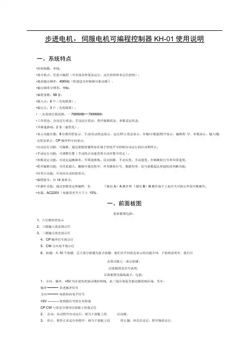
步进电机,伺服电机可编程控制器KH-01使用说明一、系统特点•控制轴数:单轴;•指令特点:任意可编程(可实现各种复杂运行:定位控制和非定位控制);•最高输出频率:40KHz(特别适合控制细分驱动器);•输岀频率分辨率:1Hz;•编程条数:99条;•输入点:6个(光电隔离);•输岀点:3个(光电隔离);• 一次连续位移范围:一7999999〜7999999;•工作状态:自动运行状态,手动运行状态,程序编辑状态,参数设定状态;•升降速曲线:2条(最优化);•显示功能位数:8位数码管显示、手动/自动状态显示、运行/停止状态显示、步数/计数值/程序显示、编辑程序,参数显示、输入/输出状态显示、CP脉冲和方向显示;•自动运行功能:可编辑,通过面板按键和加在端子的电平可控制自动运行的启动和停止;•手动运行功能:可调整位置(手动的点动速度和点动步数可设定);•参数设定功能:可设定起跳频率、升降速曲线、反向间隙、手动长度、手动速度、中断跳转行号和回零速度;•程序编辑功能:可任意插入、删除可修改程序。
具有跳转行号、数据判零、语句条数超长和超短的判断功能;•回零点功能:可双向自动回到零点;•编程指令:共14条指令;•外操作功能:通过参数设定和编程,在(限位A)A操作和(限位B)B操作端子上加开关可执行外部中断操作;•电源:AC220V(电源误差不大于土15%。
一、前面板图前面板图包括:1、八位数码管显示2、六路输入状态指示灯3、三路输岀状态指示灯4、CP脉冲信号指示灯5、CW方向电平指示灯6、按键:共10个按键,且大部分按键为复合按键,他们在不同状态表示的功能不同,下面的说明中,我们只去取功能之一表示按键。
后面板图及信号说明:后面板图为接线端子,包括:1、方向、脉冲、+5V为步进电机驱动器控制线,此三端分别连至驱动器的相应端,其中:脉冲------- 步进脉冲信号方向------- 电机转向电平信号+5V ---------- 前两路信号的公共阳端CP CW勺状态分别对应面板上的指示灯2、启动:启动程序自动运行,相当于面板上的启动键。
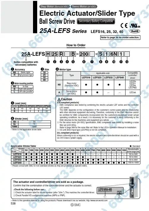
Applicable Stroke Table : Standard 501001502002503003504004505005506006507007508008509009501000Manufacturablestroke range [mm] LEFS16 ——————————50 to 500 LEFS25 ————————50 to 600 LEFS32 ————50 to 800 LEFS40—— 150 to 1000 *P lease consult with SMC for non-standard strokes as they are produced as special orders.How to Orderr Motor typeSymbol T ypeApplicable size Compatiblecontroller/driverLEFS16LEFS25LEFS32LEFS40Nil Step motor(Servo/24 VDC)LECP6LECP1LECP ALECPMJA Servo motor(24 VDC)——LECA6t Lead [mm]Symbol LEFS16LEFS25LEFS32LEFS40A10121620B56810e Motor mounting positionNil In-lineR Right side parallelL Left side parallelw Size16253240y Stroke [mm]5050to to10001000* Refer to the applicable stroke table.ModelStroke[mm]Caution[CE-compliant products]q EMC compliance was tested by combining the electric actuator LEF series and the controllerLEC series.The EMC depends on the configuration of the customer’s control panel and the relationshipwith other electrical equipment and wiring. Therefore, conformity to the EMC directive cannotbe certified for SMC components incorporated into the customer’s equipment under actualoperating conditions. As a result, it is necessary for the customer to verify conformity to theEMC directive for the machinery and equipment as a whole.w For the servo motor (24 VDC) specification, EMC compliance was tested by installing a noisefilter set (LEC-NFA).Refer to page 568 for the noise filter set. Refer to the LECA Operation Manual for installation.e CC-Link direct input type (LECPMJ) is not CE-compliant.[UL-compliant products]When conformity to UL is required, the electric actuator and controller/driver should be used with aUL1310 Class 2 power supply.Series compatible withsecondary batteriesThe actuator and controller/driver are sold as a package.Confirm that the combination of the controller/driver and the actuator is correct.<Check the following before use.>q Check the actuator label for model number (after "25A-"). This matches the controller/driver.w Check Parallel I/O configuration matches (NPN or PNP).* Refer to the operation manual for using the products. Please download it via our website, q wq AccuracyNil Basic typeH High precision type25A-LEFS25w200y6N!0Si1oReHq rBt u1!1!2Refer to page 38 for model selection.Step Motor (Servo/24 VDC)Servo Motor (24 VDC)Electric Actuator/Slider TypeBall Screw Drive Secondary Battery Compatible25A-LEFS Series LEFS16, 25, 32, 40538u Motor optionNil Without option BWith locki Actuator cable type *1Nil Without cable S Standard cable *2RRobotic cable (Flexible cable)*3*1T he standard cable should be used on fixed parts. For using on moving parts, select the robotic cable.*2 O nly available for the motor type “Step motor”.*3 F ix the motor cable protruding from the actuator to keep it unmovable. For details about fixing method, refer to Wiring/Cables in the Electric Actuators Precautions.!1 I/O cable length [m]*1, Communication plugNil Without cable (Without communication plug connector)*31 1.533*255*2S Straight type communication plug connector *3TT-branch type communication plug connector *3*1 W hen “Without controller/driver” is selected for controller/driver types, I/O cable cannot be selected. Refer to page 568 (For LECP6/LECA6), page 582 (For LECP1) or page 596 (For LECP A) if I/O cable is required.*2 W hen “Pulse input type” is selected for controller/driver types, pulse input usable only with differential. Only 1.5 m cables usable with open collector.*3 W hen “CC-Link direct input type” is selected for controller/driver types, I/O cable is not included. Only “Nil”, “S” or “T” can be selected.!2 Controller/Driver mountingNil Screw mounting DDIN rail mounting ** DIN rail is not included. Order it separately.o Actuator cable length [m]Nil Without cable1 1.5335588*A 10*B 15*C20** Produced upon receipt of order (Robotic cable only)!0 Controller/Driver type *1Nil Without controller/driver 6N LECP6/LECA6(Step data input type)NPN 6P PNP 1N LECP1*2(Programless type)NPN 1P PNP MJ LECPMJ *2 *3(CC-Link direct input type)—AN LECPA *2 *4(Pulse input type)NPN APPNP*1 F or details about controller/driver and compatible motor, refer to the compatible controller/driver below.*2 O nly available for the motor type “Step motor”.*3 Not applicable to CE.*4 W hen pulse signals are open collector, order the current limiting resistor (LEC-PA-R-l ) on page 596 separately.Compatible Controller/DriverTypeStep data input typeStep data input typeCC-Link direct input typeProgramless typePulse input typeSeries LECP6LECA6LECPMJLECP1LECPAFeatures Value (Step data) input Standard controllerCC-Link direct inputCapable of setting up operation (step data)without using a PC or teaching boxOperation by pulse signalsCompatible motorStep motor (Servo/24 VDC)Servo motor (24 VDC)Step motor (Servo/24 VDC)Maximum number of step data 64 points14 points—Power supply voltage 24 VDC Reference pagePage 560Page 560Page 600Page 576Page 590* Copper and zinc materials are used for the motors, cables, controllers/drivers.* Specifications and dimensions for the 25A-series are the same as standard products.Motor mounting position: Right side parallelMotor mounting position:In-line539Electric Actuator/Slider TypeBall Screw Drive25A-LEFS SeriesStep Motor (Servo/24 VDC) Servo Motor (24 VDC)Secondary Battery CompatibleLEF LAT LEJ LELLEYLEM LESLEPY LEPSLEY -X5LEC S LEC SS-T LEC YMotor-less11-LEFS 11-LEJSLER LEHLECLZ LC3F225A-。
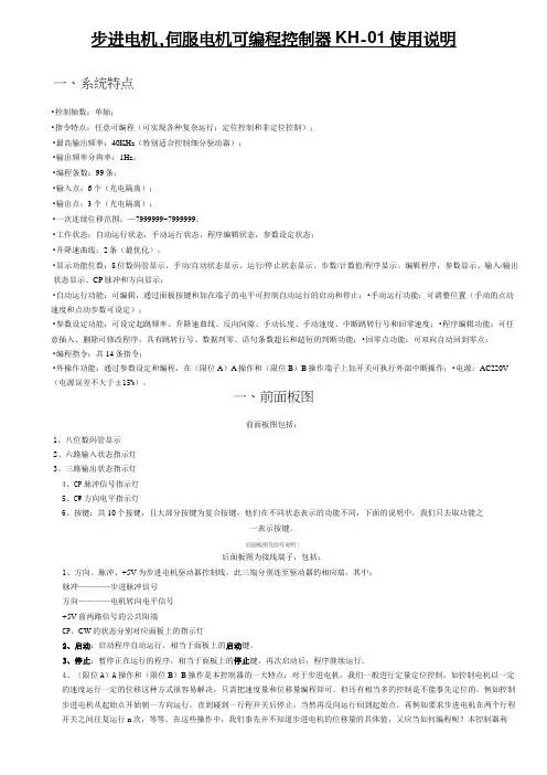
步进电机,伺服电机可编程控制器KH-01使用说明一、系统特点•控制轴数:单轴;•指令特点:任意可编程(可实现各种复杂运行:定位控制和非定位控制);•最高输出频率:40KHz(特别适合控制细分驱动器);•输出频率分辨率:1Hz;•编程条数:99条;•输入点:6个(光电隔离);•输出点:3个(光电隔离);•一次连续位移范围:—7999999~7999999;•工作状态:自动运行状态,手动运行状态,程序编辑状态,参数设定状态;•升降速曲线:2条(最优化);•显示功能位数:8位数码管显示、手动/自动状态显示、运行/停止状态显示、步数/计数值/程序显示、编辑程序,参数显示、输入/输出状态显示、CP脉冲和方向显示;•自动运行功能:可编辑,通过面板按键和加在端子的电平可控制自动运行的启动和停止;•手动运行功能:可调整位置(手动的点动速度和点动步数可设定);•参数设定功能:可设定起跳频率、升降速曲线、反向间隙、手动长度、手动速度、中断跳转行号和回零速度;•程序编辑功能:可任意插入、删除可修改程序。
具有跳转行号、数据判零、语句条数超长和超短的判断功能;•回零点功能:可双向自动回到零点;•编程指令:共14条指令;•外操作功能:通过参数设定和编程,在(限位A)A操作和(限位B)B操作端子上加开关可执行外部中断操作;•电源:AC220V (电源误差不大于±15%)。
一、前面板图前面板图包括:1、八位数码管显示2、六路输入状态指示灯3、三路输出状态指示灯4、CP脉冲信号指示灯5、CW方向电平指示灯6、按键:共10个按键,且大部分按键为复合按键,他们在不同状态表示的功能不同,下面的说明中,我们只去取功能之一表示按键。
后面板图及信号说明:后面板图为接线端子,包括:1、方向、脉冲、+5V为步进电机驱动器控制线,此三端分别连至驱动器的相应端,其中:脉冲————步进脉冲信号方向————电机转向电平信号+5V前两路信号的公共阳端CP、CW的状态分别对应面板上的指示灯2、启动:启动程序自动运行,相当于面板上的启动键。

电机,伺服电机可编程控制器AKS-01Z使用说明一、系统特点●控制轴数:单轴;●指令特点:任意可编程(可实现各种复杂运行:定位控制和非定位控制);●最高输出频率:40KHz(特别适合控制细分驱动器);●输出频率分辨率:1Hz;●编程条数:99条;输入/1234、5、6一表示按键。
后面板图及信号说明:后面板图为接线端子,包括:1、CP、CW、OPTP为步进电机驱动器控制线,此三端分别连至驱动器的相应端,其中:CP————步进脉冲信号CW————电机转向电平信号OPTO————前两路信号的公共阳端CP、CW的状态分别对应面板上的指示灯2、启动:启动程序自动运行,相当于面板上的启动键。
3、停止:暂停正在运行的程序,相当于面板上的停止键,再次启动后,程序继续运行。
4、A操作和B操作是本控制器的一大特点:对于步进电机,我们一般进行定量定位控制,如控制电机以一定的速度运行一定的位移这种方式很容易解决,只需把速度量和位移量编程即可。
但还有相当多的控制是不能事先定位的,例如控制步进电机从起始点开始朝一方向运行,直到碰到一行程开关后停止,当然再反向运行回到起始点。
再例如要求步进电机在两个行程开关之间往复运行n次,等等。
在这些操作中,我们事先并不知道步进电机的位移量的具体值,又应当如何编程呢?本控制器利用:“中断操作”,我们称之为“A操作”和“B操作”。
以“A操作”为例,工作流程为:当程序在运行时,如果“A操作”又信号输入,电机作降速停止,程序在此中断,程序记住了中断处的座标,程序跳转到“A操作”入口地址所指定的程序处运行程序。
5、输入1和输入2通过开关量输入端。
6、输出1、输出2和输出3通过开关量输出端。
7、C OM+、COM—输入输出开关量外部电源,本电源为DC12V/0.3A,COM+为正端,COM—为负端,此电源由控制器内部隔离提供。
8、成后按参数分两行显示,第一行显示参数的名称,第二行显示参数数据。
参数修改方式:进入参数设定状态后,首先显示第一行[JF-------]。
EasyHmi2100组成运动控制系统。
控制器执行运动控制的所有细节,包括脉冲和方向信号的产生,原点的复位,上下限位开关的检测,自动加减速,插补运算等等,能很方便的替代PLC的位置控制模块,IPC的运动控制卡,极大的提高性能价格比。
由于采用集散控制,上位机(PLC、IPC、EasyHmi2100)能从实时的运动控制任务中摆脱出来,更好的执行人机交互和其它控制任务。
控制器功能齐全,使用方便,价格实惠。
能实现任意两轴的直线,圆弧插补,输出脉冲达到100KHz。
控制器全部程序由本公司自主开发,可以快速,准确的为用户订制特殊曲线的插补控制命令。
如果只需要增加普通的I/O,直线和圆弧插补,请选用EasySmc 2100。
如果需要使用具有速度前瞻控制的B样条插补功能(495个控制顶点),请选用EasySmc 2130。
如果需要更高速的脉冲输出(2MHz),请选用EasySmc 2300。
二、性能指标:1、使用工业电源+24V直流供电,带反向输入保护,最大功耗10W;;2、X,Y,Z三轴独立、直线插补、圆弧插补步进控制;3、脉冲输出速度100KHz,可以满足步进电机控制的需要(1.8度,40细分的进给速度750转/分);4、梯形加减速度,防止运动过程中的失步和过冲;5、单轴最大步进步数– 16,777,215 — + 16,777,215;6、每轴各带一上限,下限的软件限位寄存器,4路旋转编码器输入;7、每轴带一原点信号,上限、下限信号输入,外部启动联锁信号;系统带一紧急故障输入信号;8、控制器具有手/自动切换功能,方便调试;9、可选择RS232,RS422,RS485通信接口,波特率2400bps,4800bps,9600bps,19200bps;USB通信,每秒钟可发送100条命令,即通信周期为10ms;10、所有I/O使用光电隔,提高抗干扰性能;4路通用输出、4路通用输入;2路10位A/D输入;11、控制器命令可接受用户订制,完成特殊曲线的插补控制;采用压扣式接线端,安装接线方便可靠。
SM-14S M C系列阀门电动装置使 用 说 明 书天津百利二通机械有限公司TIANJIN BAILI ERTONG MACHINERY CO.,LTD.目 录第一部分 SMC系列普通型产品使用说明第二部分 SMC系列整体型产品使用说明第三部分 SMC系列隔爆型产品使用说明第四部分 SMC-04~SMC-2低温型产品使用说明第一部分 SMC系列普通型产品使用说明1.概述SMC系列多回转型阀门电动装置(以下称电动装置)用于驱动控制阀瓣作直线运动的闸阀、截止阀、隔膜阀等多回转阀门。
SMC系列中的部分机座产品也可以同BA伞齿轮减速器或直齿轮减速器组合,形成SMC/BA等组合式多回转电动装置。
当SMC系列产品与HBC蜗轮减速器或JA行星减速器组合后则成为组合式部分回转电动装置,它用于驱动控制阀瓣作旋转运动的球阀、蝶阀、旋塞阀等部分回转阀门。
SMC系列电动装置可以远距离电动操作(控制室内操作),可以根据订货要求加装现场按钮灯盒,从而具备现场操作功能。
SMC系列产品的手动机构可完成现场手动操作阀门。
由于SMC/BA、SMC/HBC、SMC/JA等组合型式电动装置的控制、调节部件均在SMC系列产品上,所以本说明书同样适用于上述产品。
(图1)~(图9)所示为SMC、SMC/BA、SMC/HBC、SMC/JA普通型产品的外形主视图。
上述产品的外形和法兰连接尺寸可参见我公司有关产品样本。
所用电动装置的输出转矩、转速、转圈数、电动机功率等详见该电动装置的铭牌。
2.基本技术参数产品符合GB/T24923-2010《普通型阀门电动装置技术条件》2.1动力电源:380V、50Hz(特殊订货可提供220V、415 V、440 V、460 V、480 V、660 V、690 V,50Hz、60Hz)三项正弦交流电(根据用户要求,某些规格可提供单相220V电源的电动机)。
2.2外壳保护等级:IP65~IP67(IP68订货时提出)2.3使用环境温度:-20℃~70℃(根据用户订货要求)2.4环境相对湿度:≤90%(25℃时)2.5海拔高度:≤1000m2.6短时工作:时间定额为10、15、30min(根据电动机负载情况而定)2.7无强烈振动工况。
Other SettingsSummary of Product partsSimple Setting ModeTroubleshootingNote: Specifications are subject to change without prior notice and any obligation on the part of the manufacturer.© 2015 SMC Corporation All Rights ReservedAkihabara UDX 15F, 4-14-1, Sotokanda, Chiyoda-ku, Tokyo 101-0021, JAPANPhone: +81 3-5207-8249 Fax: +81 3-5298-5362URL Specifications/Outline with Dimensions (in mm)Refer to the product catalogue or SMC website (URL ) formore information about the product specifications and outline dimensions.PS※※-OMS0008-A InstallationMounting with bracketMount the bracket to the body with mounting screws (Self tapping screws:Nominal size 3 x 8L (2 pcs)), then set the body to the specified position.∗: Tighten the bracket mounting screws to a torque of 0.5±0.05 Nm.Self tapping screws are used, and should not be re-used several times.∗: The panel mount adapter can be rotated through 90 degrees for mounting.•Bracket A (Part No.: ZS-46-A1)•Bracket B (Part No.: ZS-46-A2)Mounting with panel mount adapterMount part (a) to the front of the body and fix it. Then insert the body with (a)into the panel until (a) comes into contact with the panel front surface. Next,WiringWiring connectionsConnections should be made with the power supply turned off.Use a separate route for the product wiring and any power or high voltagewiring. Otherwise, malfunction may result due to noise.If a commercially available switching power supply is used, be sure toground the frame ground (FG) terminal. If the switching power supply isconnected for use, switching noise will be superimposed and it will not beable to meet the product specifications. In that case, insert a noise filtersuch as a line noise filter/ferrite between the switching power supplies orchange the switching power supply to the series power supply.How to use connectorstraight out.OUT1NCNCDC(-)PipingTightening the connection threadFor connecting to the body (piping specification: -M5)After hand tightening, apply a spanner of the correctsize to the spanner flats of the piping body, and tightenwith a 1/6 to 1/4 rotation.As a reference, the tightening torque is 1 to 1.5 Nm.(When replacing the piping adapter ZS-39-N∗, tighten itusing the same method.)Piping specification: -01, -N01After hand tightening, hold the hexagonal spanner flatsof the pressure port with a spanner, and tighten with 2 to3 rotations.As a reference, the tightening torque is 3 to 5 Nm.When tightening, do not hold the Z/ISE20 body with aspanner.Default settingsWhen the pressure exceedsthe set value, the switch will beturned on. When the pressurefalls below the set value by theamount of hysteresis or more,the switch will be turned off.The default setting is to turn onthe pressure switch when thepressure reaches the centre of the atmospheric pressure and upper limit of therated pressure range. If this condition, shown to the right, is acceptable, then keepthese settings.Error indication functionThis function is to display error location and content when a problem or error has occurred.than above are displayed, please contact SMC.Refer to the SMC website (URL ) for more informationabout troubleshooting.button between1 and 3 sec.button between3 and 5 sec.∗:The outputs will continue to operate during setting.∗:If a button operation is not performed for 3 seconds during the setting, the display will flash.(This is to prevent the setting from remaining incomplete if, for instance, an operator were to leaveduring setting.)∗:3 step setting mode, simple setting mode and function selection mode settings are reflected eachother.[3 step setting mode (hysteresis mode)]orsetting can be changed in the same way.button once when the item toThe set value on the sub display (right) willstart flashing.orbutton and can be reduced withbutton.buttons are pressed and held simultaneously for 1second or longer, the set value is displayed as [- - -], and the set value will bethe same as the current pressure value automatically (snap shot function).button.button to complete the setting.The Pressure switch turns on within a set pressure range (from P1L to P1H) duringwindow comparator mode.Set P1L, the lower limit of the switch operation, and P1H, the upper limit of theswitch operation and WH1 (hysteresis) following the instructions given above.(When reversed output is selected, the sub display (left) shows [n1L] and [n1H].)∗:Setting of the normal/reverse output switching and hysteresis/window comparator modeswitching are performed with the function selection mode [F 1] OUT1 setting.valuePeak/bottom value indicationbutton inmeasurement mode.Snap shot functionbuttons for 1second or longer simultaneously. Then, the set value of the sub display (right)shows [- - -], and the values corresponding to the current pressure values areautomatically displayed.Zero-clear functionbuttons are pressed for 1 secondor longer simultaneously, the main display shows [- - -], and the reset to zero.The display returns to measurement mode automatically.Key-lock functionTo set each of these functions, refer to the SMC website(URL ) for more detailed information, or contact SMC.button between 1 and 3 seconds inmeasurement mode. [SEt] is displayed on the main display. Whenthe button is released while in the [SEt] display, the current pressurevalue is displayed on the main display, [P_1] or [n_1] is displayed onthe sub display (left), and the set value is displayed on the subdisplay (right) (Flashing).or button to set the(The snap shot function can be used.)or button to set the(The snap shot function can be used.)or button, the delay time of the switch output can be selected.button for 2 seconds or longer to complete the OUT1 setting.∗:If the button is pressed for less than 2 seconds, the setting will be returned to P_1.In the window comparator mode, set P1L, the lower limit of the switch operation,and P1H, the upper limit of the switch operation, WH1 (hysteresis) and dt1 (delaytime) following the instructions given above.(When reversed output is selected, the sub display (left) shows [n1L] and [n1H].)Function selection modebutton between 3 and 5seconds, to display [F 0]. Select todisplay the function to be changed[F]. Press and hold the buttonfor 2 seconds or longer in functionselection mode to return tomeasurement mode.∗:Some products do not have all the functions. If no function is available or selected due toconfiguration of other functions, [- - -] is displayed on the sub display (right).Names of individual partsRefer to the product catalogue or SMC website (URL )for more information about panel cut-out and mounting hole dimensions.Pressure Setting3 Step Setting Mode(URL ) for more detailed information, or contact SMC.MaintenanceHow to reset the product after a power cut or forcible de-energizingThe setting of the product will be retained as it was before a power cut orde-energizing. The output condition is also basically recovered to that before apower cut or de-energizing, but may change depending on the operatingenvironment. Therefore, check the safety of the whole installation before operatingthe product. If the installation is using accurate control, wait until the product haswarmed up (approximately 10 to 15 minutes).Safety InstructionsBefore UseDigital Pressure SwitchZSE20(F)/ISE20Thank you for purchasing an SMC ZSE20(F)/ISE20 Series Digital PressureSwitch.Please read this manual carefully before operating the product and make sure youunderstand its capabilities and limitations. Please keep this manual handy forfuture reference.Safety InstructionsThese safety instructions are intended to prevent hazardous situations and/orequipment damage.These instructions indicate the level of potential hazard with the labels of"Caution", "Warning" or "Danger". They are all important notes for safety and mustbe followed in addition to International standards (ISO/IEC) and other safetyregulations.OperatorSwitch ONAt normal output Switch OFFSet valueP_1HysteresisH_1TimePressureOther parameter settingsDefault settingThe default setting is as follows.If no problem is caused by thissetting, keep these settings.。
Other SettingsSummary of Product partsSimple Setting ModeTroubleshootingNote: Specifications are subject to change without prior notice and any obligation on the part of the manufacturer.© 2017 SMC Corporation All Rights ReservedAkihabara UDX 15F, 4-14-1, Sotokanda, Chiyoda-ku, Tokyo 101-0021, JAPANPhone: +81 3-5207-8249 Fax: +81 3-5298-5362URL Specifications/Outline with Dimensions (in mm)Refer to the product catalog or SMC website (URL ) for moreinformation about the product specifications and outline dimensions.PS※※-OMU0001 InstallationMounting with bracketMount the bracket to the body with mounting screws (Self tapping screws:Nominal size 3 x 8L (2 pcs)), then set the body to the specified position.∗: Tighten the bracket mounting screws to a torque of 0.5±0.05 Nm.Self tapping screws are used, and should not be re-used several times.∗: The panel mount adapter can be rotated through 90 degrees for mounting.•Bracket A (Part No.: ZS-46-A1)•Bracket B (Part No.: ZS-46-A2)Mounting with panel mount adapterMount part (a) to the front of the body and fix it. Then insert the body with (a) intothe panel until (a) comes into contact with the panel front surface. Next, mountpart (b) to the body from the rear and insert it until (b) comes into contact with thepanel for fixing.WiringWiring connectionsConnections should be made with the power supply turned off.Use a separate route for the product wiring and any power or high voltage wiring.Otherwise, malfunction may result due to noise.If a commercially available switching power supply is used, be sure to ground theframe ground (FG) terminal. If the switching power supply is connected for use,switching noise will be superimposed and it will not be able to meet the productspecifications. In that case, insert a noise filter such as a line noise filter/ferritebetween the switching power supplies or change the switching power supply tothe series power supply.How to use connectorConnector attachment/detachmentWhen connecting the connector, insert itstraight onto the pins, holding the lever andconnector body, and lock the connector bypushing the lever hook into the concavegroove on the housing.To detach the connector, remove the hookfrom the groove by pressing the leverdownward, and pull the connector straightout.DC(+)Pin No.OUT1OUT2FUNCDC(-)BrownBlackWhiteGrayBluePipingTightening the connection threadFor connecting to the body (piping specification: -M5)After hand tightening, apply a spanner of the correct size tothe spanner flats of the piping body, and tighten with a 1/6 to1/4 rotation.As a reference, the tightening torque is 1 to 1.5 Nm.(When replacing the piping adapter ZS-46-N∗, tighten it usingthe same method.)Piping specification: -01, -N01After hand tightening, hold the hexagonal spanner flats of thepressure port with a spanner, and tighten with 2 to 3 rotations.As a reference, the tightening torque is 3 to 5 Nm.When tightening, do not hold the pressure switch body with aspanner.Default settingsWhen the pressure exceeds the setvalue, the switch will be turned on.When the pressure falls below theset value by the amount ofhysteresis or more, the switch willbe turned off. The default setting isto turn on the pressure switch whenthe pressure reaches the centre ofthe atmospheric pressure and upper limit of the rated pressure range. If this condition,shown to the right, is acceptable, then keep these settings.Error indication functionThis function is to display error location and content when a problem or error has occurred.above are displayed, please contact SMC.Refer to the SMC website (URL ) for more information abouttroubleshooting.Power is supplied.button between1 and 3 sec.∗:The outputs will continue to operate during setting.∗:If a button operation is not performed for 3 seconds during the setting, the display will flash.(This is to prevent the setting from remaining incomplete if, for instance, an operator were to leave duringsetting.)∗:3 step setting mode, simple setting mode and function selection mode settings are reflected each other.[3 step setting mode (hysteresis mode)]orcan be changed in the same way.button once when the item to beThe set value on the sub display (right) will startflashing.orbutton.buttons are pressed and held simultaneously for 1 second orlonger, the set value is displayed as [- - -], and the set value will be the same as thecurrent pressure value automatically (snap shot function).Afterwards, it is possible to adjust the value by pressing button.button to complete the setting.The pressure switch turns on within a set pressure range (from P1L to P1H) duringwindow comparator mode.Set P1L, the lower limit of the switch operation, and P1H, the upper limit of the switchoperation and WH1 (hysteresis) following the instructions given above.(When reversed output is selected, the sub display (left) shows [n1L] and [n1H].)∗:Set OUT2 in the same way. (ex. P_2, H_2)∗:Setting of the normal/reverse output switching and hysteresis/window comparator mode switchingare performed with the function selection mode [F 1] OUT1 setting and [F 2] OUT2 setting.value[F 0] Units selection functionPeak/bottom value indicationbutton inmeasurement mode.Snap shot functionbuttons for 1 secondor longer simultaneously. Then, the set value of the sub display (right) shows [- - -], andthe values corresponding to the current pressure values are automatically displayed.Zero-clear functionbuttons are pressed for 1 second orlonger simultaneously, the main display shows [- - -], and the reset to zero.The display returns to measurement mode automatically.Key-lock functionTo set each of these functions, refer to the SMC website(URL ) for more detailed information, or contact SMC.button between 1 and 3 seconds in measurementmode. [SEt] is displayed on the main display. When the button is releasedwhile in the [SEt] display, the current pressure value is displayed on themain display, [P_1] or [n_1] is displayed on the sub display (left), and theset value is displayed on the sub display (right) (Flashing).or button to(The snap shot function can be used.)or button to set the(The snap shot function can be used.)or button, the delay time of the switch output can be selected.button for 2 seconds or longer to complete the setting.∗:If the button is pressed for less than 2 seconds, the setting will moves to the OUT2 setting.In the window comparator mode, set P1L, the lower limit of the switch operation, andP1H, the upper limit of the switch operation, WH1 (hysteresis) and dt1 (delay time)following the instructions given above.(When reversed output is selected, the sub display (left) shows [n1L] and [n1H].)∗:Set OUT2 in the same way.Function selection modebuttonbetween 3 and 5 seconds, to display [F 0].Select to display the function to be changed[F button for 2seconds or longer in function selection modeto return to measurement mode.∗:Some products do not have all the functions. If no functionis available or selected due to configuration of otherfunctions, [- - -] is displayed on the sub display (right).Names of individual partsRefer to the product catalog or SMC website (URL ) for moreinformation about panel cut-out and mounting hole dimensions.Pressure Setting3 Step Setting Mode(URL ) for more detailed information, or contact SMC.MaintenanceHow to reset the product after a power cut or forcible de-energizingThe setting of the product will be retained as it was before a power cut or de-energizing.The output condition is also basically recovered to that before a power cut or de-energizing, but may change depending on the operating environment. Therefore, checkthe safety of the whole installation before operating the product. If the installation is usingaccurate control, wait until the product has warmed up (approximately 10 to 15 minutes). Safety InstructionsBefore UseDigital Pressure SwitchZSE20A(F)/ISE20AThank you for purchasing an SMC ZSE20A(F)/ISE20A Series Digital Pressure Switch.Please read this manual carefully before operating the product and make sure youunderstand its capabilities and limitations. Please keep this manual handy for futurereference.Safety InstructionsThese safety instructions are intended to prevent hazardous situations and/orequipment damage.These instructions indicate the level of potential hazard with the labels of "Caution","Warning" or "Danger". They are all important notes for safety and must be followed inaddition to International standards (ISO/IEC) and other safety regulations.OperatorSwitch ONAt normal output Switch OFFSet valueP_1HysteresisH_1TimePressureDefault settingThe default setting is as follows.If no problem is caused by this setting,keep these settings.Connector pin numbers[F 2] Setting of OUT2Same setting as [F 1] OUT1.NOTE•The direct current power supply to be used should be UL approved as follows:Circuit (of Class 2) which is of maximum 30 Vrms (42.4 V peak), with UL1310 Class2 power supply unit or UL1585 Class 2 transformer.•The product is a UL approved product only if it has a mark on the body.。