《雪狼》造雪机说明书
- 格式:docx
- 大小:31.48 KB
- 文档页数:17


造雪机使用说明一、前言造雪机是一种能够在室外环境下制造雪花的设备,它可以让人们在没有自然降雪的情况下,创造出白茫茫的冰雪世界。
本篇文章将详细介绍造雪机的使用方法和注意事项。
二、选择合适的场地在使用造雪机之前,首先需要选择一个合适的场地。
一般来说,需要满足以下条件:1. 温度低于0℃:由于制作雪花需要将水喷洒到空气中,并借助低温使其凝结成为雪花,因此必须选取温度低于0℃的环境。
2. 空气湿度较低:空气湿度越低,则制作出来的雪花越干燥、松散。
因此,在选择场地时要尽量避免潮湿、多雾或降水频繁的区域。
3. 平整宽阔:由于造雪机需要进行喷洒和运行操作,因此选取一个平整宽阔、没有障碍物干扰的场地是非常重要的。
三、准备工作1. 连接电源:将造雪机插头插入电源插座,注意检查电源是否稳定,以免对设备造成损坏。
2. 加水:在造雪机的水箱中加入足够的水,一般来说,水箱容量是10L或20L。
建议使用纯净水或蒸馏水,以免影响雪花质量。
3. 连接气源:如果造雪机需要使用气体进行喷洒,则需要连接气源,并检查气体是否稳定、压力是否正常。
4. 开启制冷系统:如果造雪机配备了制冷系统,则需要在使用前开启制冷系统,并等待一段时间让其达到工作温度。
四、操作方法1. 启动设备:将开关调至“ON”位置,按下启动按钮即可启动设备。
此时,造雪机会开始进行喷洒操作。
2. 调节喷洒量:根据需要调节喷洒量大小。
一般来说,可以通过增加或减少出水口的开口程度来控制喷洒量大小。
3. 调节角度:根据需要调节出水口的角度。
一般来说,在较低温度下(-5℃以下),出水口应该朝下;而在较高温度下(-5℃以上),出水口应该朝上。
4. 调节距离:根据需要调节喷洒距离。
一般来说,可以通过增加或减少气压来控制喷洒距离。
5. 关闭设备:当使用完毕后,将开关调至“OFF”位置,按下停止按钮即可关闭设备。
同时,需要拔掉电源插头和气源插头,并清理设备。
五、注意事项1. 防止结冰:在使用造雪机时,由于会产生大量的水雾和水滴,在低温环境下容易结冰。
长城造雪机使用方法长城造雪机是一种先进的雪炮设备,采用高科技技术制造,可以在短时间内制造大量雪花,用于滑雪场、冰雪乐园等场所。
以下是关于长城造雪机使用方法的50条详细描述:1. 准备设备:确保长城造雪机的所有部件完好无损,包括水泵、压缩机、喷嘴等。
2. 检查环境:选择一个适合雪花制造的环境,通常需要低温和低湿度的气候。
3. 连接电源:将长城造雪机的电源线插入电源插座,确保电源稳定。
4. 连接水源:将水管连接到长城造雪机的水箱或水源处,确保供水充足。
5. 打开主电源开关:启动长城造雪机的主电源开关,待设备进入工作状态。
6. 打开压缩机:启动长城造雪机的压缩机,使其开始工作,产生高压气体。
7. 调节水压:根据实际需要,调节长城造雪机的水泵水压,一般建议在2-4兆帕。
8. 调节喷嘴角度:根据风向和风力,调节长城造雪机的喷嘴角度,确保雪花均匀覆盖目标区域。
9. 检查运行状态:观察长城造雪机是否正常运行,包括喷嘴是否喷水、压缩机是否正常工作等。
10. 调节出雪量:根据需求,调节长城造雪机的出雪量,控制雪花的制造速度和数量。
11. 定期检查:在使用过程中,定期检查长城造雪机的各个部件,确保设备正常运行。
12. 关闭设备:在使用结束后,依次关闭水泵、压缩机和主电源开关,断开电源和水源。
13. 清洁维护:每次使用结束后,对长城造雪机进行清洁维护,包括清洁喷嘴、清理水箱等部件。
14. 学习培训:使用长城造雪机前,应接受相关培训,了解设备的各项操作细节和注意事项。
15. 安全防护:使用长城造雪机时,应穿着防护服和护目镜,避免因意外喷射伤害。
16. 水源净化:使用自来水或经过净化处理的水源,以确保长城造雪机制造的雪花质量。
17. 风向预判:在使用长城造雪机时,应预先观察风向,调整喷雪位置,避免雪花被风吹散。
18. 跟踪气温:了解雪花制造需要的气温范围,确保环境温度适合雪花的形成。
19. 雪花密度:根据实际需要,调整长城造雪机的雪花密度,产生不同质地的雪花。
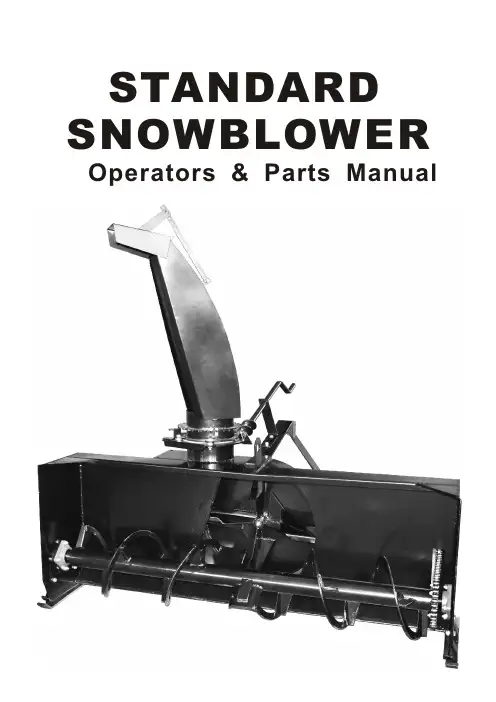
STANDARD SNOWBLOWER Operators&Parts ManualSAFETY PRECAUTIONS1.Be sure all exposed moving parts such as shafts and adapters are properly guarded and that all couplingdevices are securely attached before applying power. Do not use unless all shields are in place.2.Do not wear loose fitting clothing in the vicinity of any moving parts.3.Do not exceed recommended ground speed,recommended PTO speed, or recommended horsepower for the unit which you are using.4.Keep all persons, pets, and livestock away from unit when in use.5.Do not turn discharge chute towards persons, pets, livestock, or buildings when blower is in operation.6.Before working on, servicing, or making adjustments to equipment, disengage power, lower unit to groundlevel, shut off engine, make sure all moving parts have stopped and all pressure in the hydraulic system in relieved.7.Do not attempt to remove any obstruction fromdischarge chute until PTO is disengaged and engine is shut off.8.Do not stand on auger to service any part of blower, as auger may turn causing either, a serious fall; or, the blower fan to rotate, presenting a danger to fingers,hands, or arms in the chute assembly or blower housing. 9.Keep hands and arms away from cables and turner bar of hydraulic hood turner until engine is shut off.10.Always look to the rear before backing up.11.Be aware of the presence of people and objects that may be obscured from vision by blowing or drifted snow. Be certain that no children have tunnelled into snowbanks which are to be removed. Never let children slide down snowbanks in the vicinity of an operating blower.Colour: RedLocation: Blower SideStones or other objects may be thrown great distances by the auger, especially athigher RPMs. Do not stand in front of the blower when it is in operation.Any debris or stones which are swept into the fan can be thrown great distances. Do not allow any bystanders to stand in the path of the discharge chute.Shields are supplied for your protection. Do not remove shields and do not operate the machine unless all shields are in place.Do not service, adjust, or repair, until the PTO has been disengaged, the motor shut off, the unit lowered to the ground, and all parts have stoppedthe operator or or death.RedPTO Shaftnear any moving tractor PTOs accidentallynever attempt to repair or couple tractor engine is Do not remove Be sure that PTO freely and of theDo not operate all shields are insure that PTO shaft securely at both operating.Colour: YellowLocation: Blower BackDo not service, adjust or repair any equipmentattached to the three-point hitch hydraulics, without lowering the unit tothe ground . If work must be performed underneath the unit, block the unit in a raised position .Colour: OrangeLocation: Blower BackDo not attempt any servicing of the blower while the tractor engine is running .If the tractor PTO isaccidentally engaged the serviceman could become entangled in moving parts and be seriously injured or killed . Be certain . Be safe .Shut off the engine .Colour: YellowLocation: Blower BackEvery effortis made to ensure that a wellconstructed high quality product leaves themanufacturer . Again thedealer inspects and services each unit before it leaves his lot . To keep your blower in good operating condition,please inspect and retighten as necessary any loose nuts or studs after a half hour break in period . Thereafter periodic checks will ensure that your blower remains in top working condition .1RedBlower SideOrangeBlower SidePRE-SALE SERVICE AND SETUP OF BLOWERS1.Turn hood to point directly behind blower.(PTO side)2.Lift hood assembly off and spread a light coat of greaseon outside of blower mainframe pipe.3.Replace hood assembly.4.Install hood turner as per instructions.5.Grease shear assembly,auger bearings,and hydraulic hood turner if installed.6.Check oil level in gearbox.7.Check all bolts for tightness.8.Check auger drive chain tension and alignment.Adjust if necessary.9.Grease PTO universal joints,shield retaining collars, and inner tube of PTO.OPERATION1.When attaching the blower make certain all guards are in place.2.Ensure that the fan and auger rotate freely before connecting PTO shaft to the tractor.e proper pins and ensure that all connections are secure.4.Engage the PTO at low engine RPM and slowly increase speed to operating level.Operating speed will vary with snow,weather,and ground conditions.5.Adjust the top link of the three-point hitch to match the ground and snow conditions.Increasing the length will cause theblower to cut deeper into compacted snow,but may also cause the blower to scrape gravel or stones into the fan,which can be a danger to nearby persons,pets,livestock or buildings.Decreasing the length of the top link causes the blower to ride back on the skid shoes,raising the cutting height,thereby reducing the possibility of scraping gravel or stones into the blower.6.Adjust the deflector for the distance of throw required.Moving the adjusting bar,to shorten the distance between the pinsincreases the distance thrown.7.Be aware of the presence of people and objects that may be obscured from vision by blowing or drifted snow.Be certain thatno children have tunnelled into snowbanks which are to be removed.Never let children slide down snowbank in the vicinity of an operating blower.SERVICE1.Before servicing or adjusting,disengage the PTO,lower the unit to the ground,and shut off engine.2.To prevent freezing of hood or other moving parts apply a solution of antifreeze or light oil.3.Check gearbox oil level on a regular basis.If oil level is low,use a good quality80W-90gear oil.Change oil after50hours during break-in period.Change after700-750hours or yearly.4.Grease the shear assembly and hydraulic hood turner every five hours of operation.5.Grease the auger bearings every ten hours of operation.6.Check auger drive chain tension and alignment.Adjust if necessary.INSTALLATION INSTRUCTIONS FOR SNOWBLOWERFOR A BETTER P.T.O.SHAFT&GEARBOX OPERATIONA proper initial installation will give you years of satisfactory service on your equipment.Please read carefullyfollowing instructions which have been specially made to help you and make you satisfied with your purchase. WARNING:Unfortunately, snowblowers will be faced with forgotten or hidden objects under the snow,such as:chain,tires,stones,pieces of wood,etc… Inspite of all our efforts,machines are not built to resist all those conditions.DANGER:TOO BIG TRACTORIt is dangerous to use a tractor which is too big or too powerful.The tractor will always be able to overload the blower,even if the machine is already at maximum capacity.Tractor being very high,too large angles at P.T.O.universal joints will result,and life of universal joints will be shortened dramatically.2INSTALLATION INSTRUCTIONS FOR SNOWBLOWER-cont’dP.T.O. SHAFT ANGLESPrevious examples clearly demonstrate that universal joint angle is directly related with life of P.T.O.In order to reduce angle, it is necessary to increase the distance between snowblower and tractorH.P.P.T.O. anglesEstimated life inhours60@540RPM Using #50PTO5°10°15°20°25°450 hours 195 hours 90 hours 40 hours 20 hoursHOW TO DETERMINE P.T.O. ANGLE1) Lower blower on ground.2) Take measures A,B and L 3) Subtract B of A (A-B =C)4) Divide L by C (L/C =F)5) Compare F Factor in table to find P.T.O.angle(interpolate, if necessary).FFACTORANGLE20°10°15°25°30°62.753.752.151.75P.T.O. Shafts are made to transmit power with angles at universal joints. However, these angles should be kept to a minimum. Larger the angle, shorter the life of P.T.O.Take for example a snowblower sold for a tractor capacity of 60-70 H.P., Which would be attached to a 60 H.P.Tractor, operating at maximum capacity (60 H .P .Continuous). Too Large Angles at P.T.O. JointsReasonable Angles at P.T.O. JointsTransmission size H.P. 540 R.P.M. Joint Angle Life expectency(in hours)1020304050 607080901020304050 60708090 100 110 12054035°15°30°25°20°10°5°1020 30 4050 60 80100 150 200 250 400 500 700 1000 1500 2000 2500 3000 3500 4000 5000300EX:Transmissionn size 60 for 60 H.P. @ 540 R.P.M. with joint angle of 10” will have an expected life of 670 hours.This table is valid only for 540 R .P .M .3If it is impossible to increase the distance between snowblower and tractor,in order to maintain areasonable angle at P.T.O.,It is recommended to use a large size of P.T.O.,That is a greater capacity P.T.O.(Please refer to your dealer for more details).For snowblowers of100H.P.,an additional gearbox is also available that can be mounted on existingsnowblower gearbox,which increased the input shaft height,reducing angle at P.T.O.Joints.This gearboxcapacity.also has an input speed of1000R.P.M.,Which greatly increases P.T.O.ANGLES AT EACH END OF P.T.O.A popular habit is to change snowblower angle in order to obtain a better scraping effect.This practice can become harmful to the P.T.O.,angle at each end being unequal.There will be a fan speed variation as well as a drastic increase of load on cross and bearings.To Avoid.It is recommended to keep tractor P.T.O.Shaft and snowblower input shaft always parallel.SHEAR BOLTSShear bolts are built to break under shocks on the fan or on the auger.However,under certain circumstances, this security is not adequate.Example:A sudden high impact shock on the fan may,in some cases,break the fan shaft without breaking the shear bolt.If the shear bolt breaks,make sure to always replace it with a same category bolt(grade8.8).It is necessary to always maintain this bolt very tight,in order to keep the efficiency of the shearing mechanism.WARNING:The gearbox fan shafts are made with special alloy steel.Moreover,they are case hardened to increase capacity to shock load.These shafts cannot be broken under normal snow loads.However,undesirable objects may enter the fan and either bend or break gearbox shaft.It isunderstood that gearbox cannot be built to resist every possible overloads,and consequently,gearbox fan shafts will not be replaced under warranty.Therefore,the user of the snowblowermust be very careful.4SNOWBLOWER DIAGRAM51235678910111214151761621222324252627282930313233376343534363840414336131920239444545464748212515253254555657504942184SNOWBLOWER PARTS LISTPart#Part#DescriptionDescriptionQty.Qty.1Main Frame Lock Nut M1023Bearing SAPF-206-20 c/w flange 4Nut M65Bolt M10x206Lock Nut M12Skid Plate 7Bolt M12x30 8Bolt M16x90 910Washer 1611Bearing 6203-2RS.5/8 Idler Sprocket Spacer 121314Lock Nut M16 15Bolt M12x4016Bearing HCFS207-23 C/W Cast Flange 17Washer 12 18Lock Washer 6 19Connector Link #6020Roller Chain #60(56-1/2")21Bolt M10x30 22Auger Drive Sprocket 23Auger 24Fan25Flat Washer 3/8” 26Bolt 3/8”x1-1/4”27Lock Pin 6x40 28Turning Screw 29Bolt M6x40131113174141111282811161111111130Lock Nut M6 1Hand Crank313233343536373839404142434445464748495051525354555657Mounting Plate For Crank Handle 11Nylon WasherSpecial Washer Ø12x0.2 110Bearing 62025Lock Nut M83Mounting Plate For Chute 1Lock Bolt 2 Bolt M12x455Chute(W/O Deflector)1Bolt M8x30Bolt M6x3011Adjusting Arm 1Deflector Hinge Pin 1Cotter Pin Ø2 2Deflector 1Lock PlateMounting Bracket For Crank Handle Cross Shaft PTO1111Bolt M18x110 Lock Nut M18 Bolt M10x130 Hitch Pin Ø22x120 Lock Pin Ø8Keystock 1/4 sq.x 1-1/2 Gearbox11422116。
雪速莱雪花机操作方法
以下是雪速莱雪花机的操作方法:
1. 打开冰箱门,将冷冻室内的温度调至最低,确保冷冻室内温度达到-18 左右。
2. 将冷冻室内的冷冻料盘从冷冻室取出,放入莱雪花机的冷冻料槽中。
3. 打开莱雪花机的电源开关,确认电源指示灯亮起。
4. 调节调温旋钮,将料槽内冷冻料的温度调至-18 左右。
5. 打开料槽上的开关,开始启动雪花机。
6. 调节出料量调节旋钮,根据需要调整出料速度。
7. 使用刮冰器将产生的雪花推入杯中。
8. 根据需要添加调料或果汁,装饰雪花。
9. 完成后,关闭莱雪花机的电源开关,清理莱雪花机的冷冻料槽和刮冰器等部分。
请注意,具体操作方法可能会因不同型号的雪花机而有所不同,建议在使用前详细阅读产品说明书或向生产商咨询。
另外,操作时要注意安全,避免受伤或电器损坏。
雪花机使用方法-概述说明以及解释1.引言1.1 概述雪花机是一种用于制造雪花的设备,通过特殊的工艺和技术,能够产生逼真的雪花效果。
它通常被广泛应用于各种场合,如冰雪乐园、电影拍摄、舞台表演等。
使用雪花机能够给人们带来冬季的惬意与快乐,营造出雪花纷飞的浪漫氛围。
雪花机的构造简单而精巧。
它主要由液体储存槽、压力泵、喷雾器和控制系统等组成。
在使用前,首先需要将适量的雪花液注入液体储存槽中。
当开启电源并调节相应参数后,压力泵会将雪花液推送至喷雾器,喷雾器将液体雾化成微小的水雾颗粒,并通过高压气流将其喷出。
水雾颗粒在空气中迅速冷却凝结,形成逼真的雪花。
在使用雪花机时,我们需要注意一些事项。
首先,根据场合的需要和实际情况,合理调节雪花机的喷雾量和飞散范围,以达到理想的效果。
其次,保持雪花机的正常工作温度,避免过热或过冷。
同时,定期清洁和维护雪花机的各个部件,以确保其正常运行和延长使用寿命。
最后,在使用过程中,要注意安全防护措施,确保周围环境没有易燃物质,并远离烟雾探测器等灵敏设备。
总之,雪花机的使用方法简单易懂,但也需要我们认真细致地进行操作。
只有在正确使用的基础上,才能充分发挥雪花机的功能,创造出令人惊叹的雪花效果。
未来,随着科技的不断发展和创新,相信雪花机的性能将会进一步提升,为人们带来更加真实、美丽的雪花体验。
1.2 文章结构文章结构部分的内容如下:文章结构部分主要介绍本文的组织结构和各个章节的内容安排。
通过清晰的结构安排,读者可以更加方便地了解和理解文中的内容。
本文共分为引言、正文和结论三个主要部分。
在引言部分,我们将通过1.1小节的概述部分来简要介绍雪花机的作用和重要性,让读者对雪花机有一个初步的了解。
1.2小节将介绍本文的结构,并列举各个章节的内容安排。
1.3小节将阐明本文的目的,即帮助读者更好地掌握和使用雪花机。
正文部分是本文的核心内容,将分为2.1和2.2两个小节。
在2.1小节中,我们将详细介绍雪花机的基本原理和构造。
使用说明书版本1.0 2006年1月X E N Y X1002F X /1202F XXENYX 1002FX/1202FX2重要的安全说明详细安全说明:1) 请您阅读这些说明。
2) 请您妥善保存这些说明。
3) 请您注意所有的警告说明。
4) 请您遵守所有的操作说明。
5) 请您不要在水附近运行此机器。
6) 请您用干布清洁此机器。
7) 请您不要堵塞通风口。
在装入机器时请您注意制造厂的说明。
8) 请您不要将此机器放置在热源附近。
如散热体、炉子或其他产生热量的机器(包括放大器)。
9) 请您绝对不要移去双线插头或有接地插头的安全装置。
双线插头有两个不同宽度的插塞接点。
接地插头有两个插塞接点和第三个接地接点。
较宽的插塞接点或附加的接地接点是用来确保您的安全的。
如果随同供货的插头规格不适合您的插座,请您请电工更换适当的插座。
10) 请您正确铺设电源线,使其不会被踩踏和被尖角损坏。
请您尤其注意, 插头处, 加长电缆和电源线延伸到机器外时必须具备充分的保护。
11) 请您只使用制造厂认为合适的附加机器/配件。
12) 请您只使用制造厂提名的或随同机器一起供货的推车、固定装置、三脚架、支架或桌子。
如果您使用推车,请在移动推车时特别小心,以避免绊倒而造成受伤。
13) 在雷雨时或长期不使用机器时请您将电源插头拔出。
14) 请您只允许具备资格的售后服务人员进行保养工作。
以下情况时有必要进行保养:当机器被损坏时(如电源线或插头损),有物体或液体进入机器内部时,机器受雨淋或潮湿后,机器运行不正常时或掉落在地上后。
15) 注意! 服务维修只能由具备资格的人员进行。
为了避免触电危险,请不要进行本使用说明书中未说明的任何修理工作。
维修工作只能由具备资格的专业人员进行注意:为避免触电危险不得取下机器顶盖或后盖。
在机器内部没有用户可修理的部件。
修理工作只允许由具备资格的人员进行。
警告:为避免起火或触电危险,不得使机器遭受雨淋或潮湿,也不得有水溅入或液体滴入机器中。
版本 810906C 2021年5月型號 SCI-20/40/CA 和 SCU-20/40112頁中的1頁1. 前言此版手冊發佈於2021年5月, 由馬士基集裝箱工業公司編輯. 版權所有.此用戶手冊是針對軟件版本0357或更高版本發佈的.此手冊資訊如有變更, 恕不另行通知,亦不代表馬士基集裝箱工業公司任何部門的承諾. 然而此手冊的資訊被認為是正確的, 馬士基集裝箱工業公司對其中的任何錯誤或遺漏不承擔責任.此手冊對如下有效:型號SCI - 20/40/CA and SCU - 20/40軟體版本03572. 警告如果您還沒有熟讀此手冊指導, 沒有完全弄懂此設備和操作,請不要操作或維修此製冷機組.在沒有斷開電源插頭之前請不要對機組動焊. 而且, 還需要斷開電源偵測模組與主控制器(如果安裝了貓也需要斷開).在檢查電控箱內部時請斷開機組的主供電電源.機組充注了R134a或R513A製冷劑和BSE 55型號的酯類潤滑油. 不要使用任何其它型號的製冷劑或潤滑油. 不要使用污染的製冷劑或潤滑油. 永遠不要向大氣中直接排放製冷劑. 請根據當地法律使用資源回收裝置.在維修過程中, 請注意製冷劑工作時, 產生高溫和低溫並伴有高壓的, 如果處理不當可能會造成人員受傷.在回收和製冷系統維修過程中, 個人防護用品必須穿戴齊全.在釺焊時要確保銅管內無殘留的液體製冷劑. 這可能會導致銅管爆炸.請注意一些型號的機組的吸氣壓力感測器(Psuc)和排氣壓力感測器(Pdis)沒有安裝閥針.我們不建議用PH值低於7的肥皂/洗滌劑來清洗冷藏箱內. 然而,如果這已經發生了, 請使用 PH值介於 7 到 9 之間的洗滌劑透過馬達檢查視窗來清洗蒸發器盤管. 這步清洗對減少蒸發器盤管腐蝕的風險至關重要.當箱內氧氣含量低於20.9%時不要進入箱內,也不要打開馬達服務蓋板. 無論是維修機組還是拆貨, 進入之前請務必進行通風. 通風時要遠離門端.人體對低氧環境的反應:112頁中的2頁3. 內容1. 前言 (1)2. 警告 (1)3. 內容 (2)4. 職權範圍 (6)5. 總覽 (8)6. 功能描述 (9)6.1 啟動過程 (9)6.2 溫度控制 (9)6.3 容量控制和限制器 (9)6.4 電路控制 (11)6.5 膨脹閥.... (11)6.6 經濟器閥 (11)6.7 除濕........ (11)6.8 冷凝風扇 (12)6.9 蒸發風扇 (12)6.10 化霜功能 (13)6.11 警報回應系統 (13)6.12 資料記錄 (13)7. 測試 (16)7.1 功能測試 (16)7.2長PTI (17)7.3 短PTI (17)7.4 氣調 PTI (17)8. 製冷系統資料 (18)8.1 製冷劑充注 (18)8.2 規範總覽 (18)8.3 壓縮機 – 馬達組件 (18)8.4 變頻器 (FC) (18)8.5 蒸發器盤管 (18)8.6 蒸發器盤管加熱器 (18)8.7 蒸發器風扇 (19)8.8 蒸發器風扇馬達 (19)8.9 冷凝器盤管 (19)8.10 冷凝器風扇 (19)8.11 冷凝器風扇馬達 (20)8.12 水冷冷凝器 (可選的) (20)8.13 新風交換 (20)8.14 新風交換馬達 (20)8.15 經濟器 (21)8.16 製冷控制 (21)8.17 真空泵, 包含泵加熱器 (21)8.18 電氣參數 (21)8.19 斷路器 (21)8.20 接觸器 (21)8.21 高壓切斷開關 (21)8.22 易熔塞, 儲液罐 (22)8.23 保險絲 (22)8.24 電纜插頭 (22)8.25 電纜線 (22)8.26 USDA插口規範 (22)112頁中的3頁8.27 O2 感測器 (22)8.28 CO2 感測器 (22)8.29 溫度感測器, 包括 USDA (23)8.30 濕度傳感器 (23)8.31 CA 壓力感測器 (23)8.32 壓力感測器 (23)8.33 其它項 (23)9. 使用者介面 (24)9.1 指示燈 (24)9.2 顯示幕 (24)9.3 按鍵板 (25)10. 菜單綜述 (26)10.1 頁面總體佈局 (26)10.2 使用游標 (27)10.3 改變參數 (27)10.4 啟動一個功能 (27)10.5 新風交換介面 (27)11. 操作 (28)11.1 功能表結構 (28)11.2 操作總覽 (29)11.3 溫度設置 (29)11.4 喚醒模式 (29)11.5 顯示幕對比度調節 (29)11.6 溫度單位轉換 (29)11.7 查看溫度曲線 (29)11.8 水冷開啟/關閉 (30)11.9 PTI 或功能測試 (30)11.10 資訊功能表 (33)11.11 原始感測器數值 (37)11.12 操作功能表設定 (38)11.13 程式 (39)11.13.1 多設定溫度程式, MTS (39)11.13.2 自動冷處理, ACT (40)11.13.3 鮮花模式 (42)11.14 應用設置 (43)11.14.1 AV/AV+ (43)11.14.2 CA......... .. (43)11.15 手動化霜 (45)11.16 警報 (45)11.17 服務功能設置 (46)11.18 手動運行 (47)11.18.1 變頻器自檢 (48)11.19 數據查看 (49)11.20 時間調整 (49)11.21 執行時間計數器 (50)11.22 配置.... (51)11.22.1 StarConomy 節能模式 (52)11.23 系列號 (53)11.24 USB菜單.... .. (54)11.25 維護保養 (55)11.26 數據機 (55)12. 外接介面 (55)12.1 基本要求 (56)12.2 外接介面術語清單 (56)12.3 功能總覽 (56)112頁中的4頁13. 事件 (57)14. 詳細警報描述 (60)14.1 警報列表 (60)15. Star Cool 機組安裝尺寸 (65)16. 馬達, 溫度感測器, 濕度感測器和新風交換感測器的位置 (66)17. 閥的位置 (67)18. 馬達, 溫度感測器, 濕度感測器和新風交換感測器的位置 (68)19. 電控箱示意圖 (69)20. AV和CA部件位置 (70)21. 更換 (73)21.1 更換蒸發器馬達和風扇 (73)21.2 更換冷凝器馬達和風扇 (73)21.3 更換蒸發器盤管 (74)21.4 更換蒸發器加熱器 (75)21.5 更換變頻器 (76)21.6 更換壓縮機 (77)21.7 更換壓縮機閥板/缸頭墊片 (78)21.8 更換乾燥篩檢程式 (79)22. 維護和維修 (79)22.1 回收製冷劑 (79)22.2 壓縮機排空和操作 (80)22.3 壓縮機排空(更換後) (80)22.4 回收和抽空 (81)22.5 試壓 (81)22.6 充注製冷劑 (82)22.6.1 空機組充注 (82)22.6.2 已有部分製冷劑充注 (82)22.7 檢漏 (83)22.8 壓縮機 (83)22.8.1 檢查油位 (83)22.8.2 壓縮機泄油 (83)22.8.3 加注壓縮機油 (84)22.9 釺焊 (84)22.9.1 電焊 (85)22.10 校驗新風交換感測器 (85)22.11 通過StarView校驗溫度感測器 (85)23. CA服務和故障排除 (85)23.1 集裝箱通風流程 (85)23.2 更換真空泵油過濾器和油 (86)23.3 真空系統故障診斷 (88)23.4 更換真空泵加熱器 (89)23.5 CA 裝貨準備 (89)23.6 門帘固定膠條安裝 (89)23.7 門帘安裝 (90)23.8 CA箱氣密檢測 (91)23.9 CA+ 充氣 (91)112頁中的5頁24. 故障診斷總則 (93)25. 應急操作 (93)25.1 FC 變頻器旁通 (93)25.1.1 FC 1.0 和 FC 1.1 (93)25.1.2 FC 2.0 (94)25.2 控制器旁通 (94)25.3 蒸發器馬達旁通 (94)26. 表格 (95)26.1 資料描述 (95)26.2 溫度感測器 - 電阻表 (97)26.3 溫度感測器 - 電壓表 (98)26.4 新風感測器 電壓 - m3/h表 針對35 CMH (99)26.5 新風感測器 電壓 - m3/h表 針對75 CMH (99)26.6 電壓 - 壓力錶, 低壓壓力感測器(NSK) + DST (100)26.7 電壓 - 壓力錶, 低壓壓力感測器 (AKS (101)26.8 電壓 - 壓力錶, 高壓壓力感測器(NSK) + DST (102)26.9 電壓 - 壓力錶, 高壓壓力感測器 (AKS) (103)26.10 壓力 - 溫度錶 R134a (104)26.11 壓力 - 溫度錶 R513A (104)26.12 扭矩要求 (105)27 圖表 (106)27.1 P & I diagram (106)27.2 CA 功能總覽 - 兩個版本 (107)28. 電路接線圖 - 帶子控制器的 CIM 6.0 (109)29. 電路接線圖 - CIM 6.1 (110)30. 電路接線圖 - CIM 6.2 (111)31. 電路接線圖 - 帶子控制器的 CIM 6.2 (112)112頁中的6頁4. 職權範圍112頁中的7頁112頁中的8頁5. 總覽冷星STAR COOL冷機, 機型號為SCU-40 和 SCI-40,是基於製冷劑R134a或R513A在通電後能夠進行製冷和加熱的機組.此機組的設計保持貨物溫度範圍是 -30°C (-22°F) to +30°C (+86°F). 此機組的設計適用環境溫度範圍是 -30°C (-22°F) to +50°C (+122°F).機組前外框是由海運等級的鋁材料製成的, 5000 和 6000 系列, 被設計成完全可以用來做為集裝箱的端壁. 機組的後背板是由可以接觸食品的材料做成的.機組是以完全適用於海運環境來設計的並做如下規範:• 含鹽霧空氣, 海浪飛沫, 和高濕度.• 橫搖: 每面30° 振幅, 週期13秒.• 縱搖: 每面6° 振幅, 週期8秒.• 永久傾斜: 每面15°.• 衝擊: 橫向2g,縱向 5g.• 振動: 在船上, 卡車上, 和鐵路上可能遇見的各式振動.機組包含如下模組:• 框架模組• 冷凝器/壓縮機模組• 蒸發器模組• 蒸發器風扇模組機組的製冷系統配備了一個雙級壓縮機, 並通過一個變頻器進行驅動.此製冷系統也配備了一個經濟器, 它用來對從儲液罐到蒸發器的液體製冷劑進行過冷, 從而增加機組的製冷量.蒸發器和經濟器是由電子膨脹閥來進行控制的.此設備根據ISO 1496-2設計的供電電源為3相初級電源:50 Hz (+/- 2.5), 360-460 V AC (最高 465 V AC) 或 60 Hz (+/- 2.5), 400-500 V AC (最高 535 V AC). 控制電壓是由一個一體式的雙繞組變壓器提供的. 一個繞組輸出電壓18.6-32.0 V AC (供給RMM貓), 另外一組電壓輸出為20.5-35.7 V AC並在控制器裡轉換成直流電壓(給控制器和接觸器). 輸出電壓取決於輸入電壓. 一個自動的電源檢測和修正系統, 可以確保風扇馬達的正確轉向.這跟主電源的相序沒有關係, 但要確保所有的風扇馬達的接線是正確的.一個可選配的水冷冷凝器安裝在風冷冷凝器下端. 水冷冷凝器可以允許機組在甲板下方運行, 那裡沒有通風, 要確保外接水冷系統接通.機組為底部送風, 頂部回風回到蒸發器盤管上方 (底部送風).機組具有完全電腦化控制的自動除濕功能. 除濕設定範圍是 95 – 65% RH (或關閉新風以達到低至 50%的設定). 機組可以控制到最低值. 只有當控制溫度進入設定溫度範圍後除濕功能才能啟動. 機組裝配有加熱器, 安裝在蒸發器盤管下面, 用來進行除濕. 在經濟Economy模式下除濕功能也能啟動.機組配有雙化霜系統.系統配有一個熱氣閥, 用熱氣來輔助蒸發器盤管化霜. 而且,安裝在蒸發器盤管下面的加熱器在除霜時也會啟動. 雙化霜系統可以確保快速的完成化霜從而減少因為化霜產生的熱量對箱內溫度的影響. 雙化霜系統也能夠保證熱量均勻的分配到蒸發器盤管各個角落. 這可以防止蒸發器局部的冰不能被順利融掉. 雙化霜系統,熱氣和加熱器, 是獨立的. 這可以確保隨時都能開啟化霜過程. 嵌入到軟體裡的自動化霜系統可以確保蒸發器盤管上不會被冰封住.電子控制器是由Bitzer Electronics製造的, 在保鮮模式下控制供風溫度 (設定溫度大於等於 -5°C (+23°F), 在冷凍模式下控制回風溫度 (設定溫度小於 -5°C (+23°F). 控制器精度 ±0.25°C (±0.45°F). 機組控制蒸發器風扇以低速和高速運行.通過控制器操作介面, 中可以選擇普通模式Normal或經濟模式Economy. 在經濟模式Economy下蒸發器風扇一直低速轉. 在普通模式Normal下蒸發器風扇以高速或低速運轉, 取決於保鮮還是冷凍模式.機組配有資料記錄儀, 其嵌入到控制器裡了. 資料記錄時間間隔是預設好的, 可以選擇15, 30, 60, 120, 或 240 分鐘. USDA 感測器 (3 根) 和cargo貨物溫度感測器的資料記錄時間間隔是1小時, 這是根據USDA 的要求做的設置. 以1小時做為資料記錄時間間隔算, 資料存儲可以達到365天. 資料記錄的精度為 ±0.25°C (±0.45°F). 資料可通過電腦端 (Star-view)和Psion Logman從機組的高速串口處進行提取. 也可以通過手機APP和Star Cool Dongle (藍牙適配器)來進行提取.機組配有備用電池, 在機組斷電後可以繼續記錄資料120次. 對CIM 6, 電池是可充電的. 對CIM 5, 電池是不可充電的.根據ISO 標準 10368, 控制器可以和遠端監控設備進行通訊. 事件events, 警報alarms, 和資料datalogs可以通過各種諸如Refcon, Logman, StarView等各種系統進行下載.112頁中的9頁6. 功能描述6.1 啟動步驟啟動分為5步:1. 初始化: 控制器自檢.2. 穩定化: 蒸發器風扇高速運行以確保箱內的溫度感測器測量的是當前溫度.3. 曲軸箱加熱: 如果Tamb環境溫度低於2°C (36°F) 變頻器會加熱壓縮機線圈直到Tfc變頻器溫度超過12°C (54°F).4. 暖機.5. 結束: 切換到正常的溫度和參數控制模式.6.2 溫度控制溫度控制功能已經潛入到了控制器的系統中.這個功能有兩種模式:1. 保鮮如果設定溫度Tset大於或等於-5°C (+23°F) 則進入到保鮮模式.如果是製冷狀態則實際控制溫度Tact = Tsup供風溫度, 如果是加熱狀態則實際控制溫度Tact = Tret 回風溫度. 2. 冷凍如果設定溫度Tset小於 -5°C (+23°F) 則進入到冷凍模式並且實際控制溫度Tact = Tret 回風溫度.保鮮和冷凍模式的分界溫度取決於軟體版本和客戶要求.溫度控制是進入到下來或加熱模式取決於實際溫度Tact是高於還是低於設定溫度Tset. 只要是實際溫度未進入到設定溫度Tset ± 1.5°C範圍內, 這個功能就會保持下來或加熱模式. 如果實際溫度進入到溫度範圍內, 這個綠色的IN-RANGE 範圍內指示燈就會開始閃爍. 當實際溫度進入到設定溫度Tset ± 1.5°C 範圍內超過30分鐘, 則綠色的溫度範圍內指示燈IN-RANGE就會變成常亮.如果實際溫度超出溫度範圍超過2小時, 溫度範圍內指示燈IN-RANGE將會開始閃爍. 實際溫度超出溫度範圍超過4小時之後, 將會產生一個超出溫度範圍的警報. 根據實際溫度Tact和設定溫度Tset等輸入參數這個功能會通過控制器計算需求的容量. 需求的容量CapReq是指想要取得的製冷/加熱容量. 需求的容量CapReq數值範圍是從–100% 到 +100%.–100%是指最大的製冷量, +100%是指最大的加熱量.保鮮模式冷凍模式6.3 容量控制和限制器根據需要的容量, 此功能判斷運行模式並控制各個系統部件(壓縮機, 閥, 加熱器) 以確保取得壓縮機最少的停機時間. 此功能有5個檔位元 (模式). 根據需要的容量, 來決定進入哪個檔位.壓縮機頻率是由當前模式直接決定的. 蒸發器加熱器, 不同的是, 它的檔位是獨立的. 模式切換是有一個過程的,為了保持各個模式之間平穩過渡.機組的容量控制在最大的製冷量 (-100% capacity) 和最大的加熱量 (+100% capacity) 之間. 這是通過變頻器調節壓縮機轉速或對壓縮機進行開/關調節. 在最大的加熱量 (+100% capacity) 內機組使用加熱器加熱, 進入到容量範圍後會對加熱器進行脈衝調節來控制加熱量.下圖顯示了容量範圍.System CapacityHeating %如果任何一個限制器被觸發, 壓縮機轉速將會降低從而使機組容量降低. 當一個限制器變為活躍後, 它將會在顯示幕主頁上狀態列裡顯示出來. 限制器的類型可以在資訊功能表 , 行I40可以看到.限制器類型:• TC冷凝溫度, 最大的冷凝壓力 (和溫度) 通常出現在溫度下拉的時候. 如果此機組和其它的Star Cool機組比較起來製冷量低, 清潔冷凝器盤管, 檢查排氣壓力Pdis, 檢查冷凝器馬達的功能和轉向.• IFC變頻器電流, 變頻器FC 最高的限電流.它出現的典型條件是在溫度下拉過程中尤其是環境溫度高於25°C (77°F).如果此機組跟其它的Star Cool 機組比較起來製冷量明顯較低, 請參考警報AL 511進行故障診斷尤其是注意檢查製冷劑液位 (是否過量充注).• TFC變頻器溫度, 變頻器FC的最高溫度. 它出現的典型條件是在溫度下拉過程中尤其是環境溫度高於40°C (104°F).如果此機組跟其它的Star Cool 機組比較起來製冷量明顯較低, 請參考警報AL 511進行故障診斷.• T0蒸發溫度, 最低的蒸發壓力很少被啟動. 如果這個限制器活躍超過2分鐘, 檢查製冷劑液位 (充注不足), 檢查吸氣壓力Psuc和吸氣溫度Tsuc, 檢查膨脹閥Vexp和低壓閥板.• ITOT, 通過降低壓縮機轉速來控制機組的總電流在範圍內. 它通常會在拉溫時尤其是環境溫度高於40°C (104°F)時出現. 當總電流達到13.5 A後壓縮機允許上升的頻率會分佈降低, 當總電流達到17.5 A時壓縮機頻率會被最大程度的降低以避免出現警報AL 421從而造成機組停機甚至出現斷路器跳閘的情況.多個限制器可能同時變成活躍. 多個限制器參數會被迴圈顯示. 最緊急的參數會被用來控制容量. 如果限制參數高於需要的容量變化, 容量實際會降低而不會增加. 比如當環境溫度很高時, 需求的容量會要求提升變頻器FC 的溫度, 當變頻器溫度超限時, 限制器會降低容量直到進入到一個對變頻器安全並穩定的運行狀態.6.5 膨脹閥此功能確保蒸發器過熱度(SH)為最優並計算和控制膨脹閥的開度(SHVod). 此功能只有在壓縮機工作時才生效. 壓縮機停機時膨脹閥是關閉的. 膨脹閥功能吧包含三個子功能:1. MSS (Minimum Stable Superheat search)最小穩定過熱度搜尋此功能在最小過熱度SHmin和最大過熱度SHmax之間搜尋最小的穩定過熱度. SHact: = Tsuc - T0 (Psuc)2. 過熱控制功能結果是控制膨脹閥 (Vexp)的開度. 在啟動過程中開度是0%. 電子膨脹閥使一個全開或全關的閥,它的開度是由在一個迴圈的固定時間段內開啟的時間量來決定的.3. MOP (Maximum Operating Pressure)最大的工作壓力MOP功能是為了防止吸氣壓力變得太高.6.6 經濟器閥此功能是過冷進入到蒸發器之前的液路製冷劑同時要冷卻變頻器. 除此之外, 製冷量會提高同時排氣壓力也會將帶. 功能輸出結果是經濟器膨脹閥 (Veco)開度.經濟器有兩種控制模式:1. 過熱度控制閥的開度是由計算的脈衝時間控制的.2. 變頻器冷卻壓縮機工作時此功能才啟動.6.7 除濕除濕功能是指通過啟動加熱器來降低箱內空氣中的濕度. 只用當實際溫度進入到溫度範圍以後此功能才會啟動. 除濕的取得是通過降低蒸發器盤管的表面溫度來實現的. 當加熱器啟動後就會升高蒸發器盤管的溫度從而機組會提升製冷量來降低蒸發溫度.此功能有3中模式:1. 關閉除濕功能處在關閉狀態.2. 活躍當箱內實際濕度RH高於設定的濕度值RHSet加熱器(Hevap)就會啟動,當RH低於RHSet – 3 [%]加熱器就會關閉. 除濕設定值可以設定在50% 到 95%之間. 低除濕範圍50% to 64%之間不允許打開新風交換, 而且蒸發器馬達低速運行. 除濕範圍在65% - 95%之間允許新風交換打開, 蒸發器馬達高速運行.3. 覆蓋當滿足如下條件時除濕會被覆蓋:- 製冷量超過80%- 加熱量需求較大- PTI - 出現致命警報- 無變頻器FC運行- 手動運行模式啟動- 化霜其它備註即使覆蓋功能被啟動了除濕符合 還是會出現在顯示幕上.加熱器符合 會隨著加熱器的開關而顯示或消失.除濕功能關閉設置了工作中如果除濕功能活躍:6.8 冷凝器風扇冷凝器風扇控制是通過冷凝器風迴圈來降低冷凝壓力. 如果機組用的是水冷, 冷凝壓力控制也監測壓縮機排氣壓力. 此功能只在自動運行模式下起作用.冷凝壓力控制有兩種主要途徑:1. 風冷在風冷模式下通風有如下工作方式:取決於壓縮機的排氣壓力, 冷凝風扇或者關閉或者: 高速和低速運行. 冷凝風扇有4種運行模式: 關閉, 低速, 高速 和高低速切換(每兩分鐘為時間間隔).當環境溫度Tamb高於48°C (118°F)或壓縮機排氣壓力一直保持較高, 冷凝風扇會持續高速運行.2. 水冷如果冷凝風扇執行時間超過1小時, 將會產生一個警報.冷凝風扇冷凝風扇有4種運行模式: 關閉, 低速, 高速 和高低速切換(每兩分鐘為時間間隔).6.9 蒸發器風扇蒸發器風扇功能是確保風扇的轉速正確(高或低). 此功能只在自動模式下啟動.此功能有2種模式:1. 正常Normal冷凍模式下滿足如下條件為低速運行:- 設定溫度Tset 大於等於 0°C (32°F)- 無新風交換- 除濕功能關閉或濕度設定低於65% 否則高速運行.2. 經濟Economy蒸發器風扇持續低速運行. 除非: 當Tret > Tsup + 8°C (14°F) 時高速運行, 直到 Tret > Tsup + 3°C (5°F). Economy模式需要人工打開.6.10 化霜功能化霜功能確保蒸發器結霜正常除掉. 化霜是自動的.化霜啟動• 自動化霜, 表示蒸發器需要化霜時化霜才會啟動.化霜間隔• 按需化霜系統一直監測著蒸發器盤管溫度以防止蒸發器被冰堵住. 如果系統報告蒸發器被冰堵住, 那自動化霜就會啟動.• 兩次除霜之間的最短時間為2½小時, 具體取決於操作模式.實際化霜的方式是由空氣化霜air defrost, 熱氣化霜hot gas, 和加熱器化霜electrical heaters組成的並有4步:1. 等待在等待化霜時以下參數一直被監測並更新距離化霜的時間:- 壓縮機運行- 發溫度T0低於最小的蒸發溫度T0min.等待步驟如遇見下面情況會被終止:- 計算的蒸發器覆蓋的冰量高於臨界水準(自動化霜)- 手動化霜開啟(手動化霜開始)2. 化霜準備等待冷凝溫度高於50°C (122°F), 但不超過300秒.3. 執行化霜開始執行. 在航程資料裡會記錄化霜開始事件Event. 製冷停止, 壓縮機啟動, 只進入暖機模式. 蒸發器風扇停止.蒸發器加熱器啟動. 壓縮機以全速運行的83%的固定頻率運行. 膨脹閥關閉. 熱氣閥啟動, 熱氣被壓縮機直接打進蒸發器裡在管路裡面進行加熱. 當蒸發器溫度(Tevap)高於化霜終止溫度2分鐘並且蒸發溫度T0高於1°C超1分鐘化霜終止.或超過最長的化霜時間. 化霜結束事件會記錄在資料記錄裡, 當前的化霜時間間隔和蒸發器溫度Tevap也會被記錄.4. 結束結束模式分為兩步:- 蒸發器會被重新冷卻以防止當蒸發器風扇啟動後把蒸發器上余留的水吹進箱內.- 蒸發器風扇低速運行以防止蒸發器閃蒸並確保控制器順利切換到正常的製冷模式. 化霜結束後, 機組會以化霜之前的設定溫度為准恢復到正常的製冷模式.基本資訊如果蒸發器溫度感測器Tevap出現故障, 自動適配化霜會啟動, 和正常化霜時間間隔比較起來它的化霜時間間隔會短一些. 設定溫度的改變會引起化霜時間間隔的重新計算, 如果化霜條件滿足的話會開啟化霜. 當手動化霜開啟時當前的化霜間隔會被重置為默認的化霜間隔.手動化霜終止一旦手動化霜終止, 機組會進入化霜結束模式. 當手動化霜啟動後自動適配化霜不會發生.關於使用者介面在化霜功能執行過程中化霜符合會出現在螢幕上.其它補充在化霜過程中如果選擇了服務模式或PTI模式, 當前的化霜模式會終止並且如果化霜正進入到尾聲則下次化霜時間被設置為當前值.如果因為某種原因在化霜過程中機組關機了並且關機時間小於12個小時, 當電源恢復後機組會重進進入到剩餘的化霜過程.如果關機時間超過12小時, 機組會跳出化霜過程並且進入到等待模式.6.11 警報回應系統 (AAS)此功能用來處理當有壞的感測器出現後機組如何應對. 此策略是用其它的感測器數值加常熟來取代壞的感測器數值從而讓機組在有所降低的控制精度下仍能保持運行.6.12 資料記錄控制器中含有資料記錄儀來記錄機組運行的各項參數. 資料記錄含有4項內容:• 數據• 擴展資料• 警報• 事件數據數據查看:• 顯示幕上功能表L01, 可以查看溫度文本.• 顯示幕上功能表L03, 可以查看溫度圖表.• 可通過程式RefCon及其RMM數據機和電纜線來進行查看.• 利用資料口通過專用程式, LogMan設備, 在PSION pda上來進行提取和查看.• 利用資料口通過StarView在筆記型電腦上進行提取和查看.當一個警報出現後它將會觸發一個完整的記錄, 但每15分鐘最多記錄一個.當資料記錄時間間隔設置為預設每小時記錄一次則資料記錄儀可記錄大約10.000記錄或超過1年的記錄.下面清單顯示了通過Starview和Psion Logman軟體下載的資料:D33Extended Log Type 2E x t e n d e d L o g T y p e 2D34D35D36D37D38D39D40D41D42D43D44CA datalog C A d a t a l o gD45D46D47D48D49D50Extended Log Type 3E x t e n d e d L o g T y p e 3D51D52D53D54D55D56D57Extended Log Type 4E x t e n d e d L o g T y p e 4D58D59D60D61D62D63D64D65標題Header可以通過Refcon, Logman, StarView,USB系統提取,可以通過Refcon, LogView和StarView系統查看. 擴展資料Extended Log Type 1只能通過Logman和StarView提取並生成LogView和StarView檔. 擴展資料Extended Log Type 2只能通過StarView提取並查看. StarView程式是一個專門為Star cool機組設計的程式,它通過機組的資料提取口和PC機進行通訊.7. 測試機組有5種類型的測試:1. 功能測試-Fuction test2. 長PTI測試-Full PTI (航程預檢)3. 短PTI測試-Short PTI (航程預檢)4. 智慧航程檢測-ITI (Intelligent Trip Inspection)5. 氣調PTI測試-CA PTI (Pre-Trip Inspection)ITI (Intelligent Trip Inspection)是在貨物運輸過程中執行的機組自檢程式. 目的是減免常規的當航程結束並卸貨後需要執行的PTI 檢測.PTI測試時在功能測試的基礎上再進行容量測試的檢測. 容量測試要求在一定的時間限定範圍內實際溫度要達到要求的設定溫度.當測試開始時, 一個事件event會在資料記錄裡產生.在功能測試和PTI測試過程中警報系統任然保持活躍. 如果在測試過程中出現了警報, 警報會在顯示幕上顯示, 跟正常的運行過程中出現警報是一樣的. 當測試過程中出現致命警報 (fatal alarm)時測試會停止, 機組會保持靜止狀態.當功能或PTI子測試失敗後會觸發警報”PTI FAILURE”. 當功能或PTI子測試通過後會生成事件”Test status”並顯示在顯示幕上. 詳細資訊, 請參考事件event列表.測試之前要清除所有的警報. 如果有活躍警報伴隨時開啟功能測試或PTI 測試,測試總會失敗即使各個單步測試都通過了.PTI功能表裡有總測試狀態和各個分步測試的狀態, 每一步都有自己的索引編號. 在斷電狀態下只有PTI的總測試狀態會被記錄. PTI測試開啟時資料會記錄一個航程開始trip start事件.7.1 功能測試功能測試是機組的各個部件檢測 (非破壞性檢測).測試是基於GO/NO GO的程式. 所有的測試必須每一步都通過功能測試,測試的結果才是PASS. 功能測試裡的單步也是可以單獨測試的.備註: 如果在壓縮機測試之前壓縮機曲軸箱裡有過多的液體(功能測試的一步), 壓縮機測試將會因為過高的中壓而導致失敗. 這些液體需要蒸發出來. 讓機組在製冷狀態下先運行約10分鐘左右在開啟PTI測試或功能測試.功能測試包含如下項目:1. 初始化 PTI – init2. 控制器測試3. 電源測試4. 蒸發器馬達 (Mevap)5. 冷凝器馬達 (Mcond)6. 加熱器 (Hevap)7. 壓縮機和閥測試 (Vexp, Vhg and Veco)8. 測試結果對於Star Cool CA機組來說下面這些項目會同功能測試一起測試:9. 標準功能測試10. 二氧化碳感測器 t11. 氧氣感測器12. 新風交換馬達13. 真空泵加熱器測試結果14.。

ILLUSTRATED PARTS LISTMODEL NUMBER ST 230P PRODUCT NUMBER 961 93 01-01 MFG. ID. NUMBER 96193010103KEY PARTNO. NO. DESCRIPTION1 501 14 96-01 GEARBOX AUGER2 586 60 72-02 IMPELLER STEEL3 587 40 24-01 PULLEY IMPELLER – SCREW ON4 585 05 69-01 CHUTE DISCHARGE BASE5 532 18 40-95 BRACKET CORNER DISCHARGE BASE6 588 07 75-01 BOLT SHEAR 1/4-207 873 80 04-00 NUT NYLOCK 1/4-208 585 69 13-01 NUT FLANGE NYLOCK 5/16-18 - BLK9 585 69 12-01 BOLT CARRIAGE WAFER HEAD 5/16-18 X 5/8 BLK10 581 63 20-02 BRACKET BELT KEEPER LOWER11 581 59 25-02 BRACKET INTERFACE12 532 19 87-91 BEARING BALL13 532 16 31-83 SCREW HEX HEAD 5/16-18 X 5/814 532 42 79-42 NUT FLANGE NYLOCK 5/16-1815 587 58 72-02 LOWER AUGER BELT GUIDEKEY PART NO. NO. DESCRIPTION KEY PART NO. NO. DESCRIPTIONKEY PART NO. NO. DESCRIPTION NOTE: All component dimensions given in U.S. inches. 1 inch = 25.4 mm1205.09.014-C1 532 42 11-24 AUGER ASSEMBL Y 30 LH 2532 42 11-25AUGER ASSEMBL Y 30 RH05.09.032-B12345X5X1 581 70 83-91 AUGER HOUSING2 532 41 62-70 SCRAPER BAR3 872 27 05-05 CARRIAGE BOLT 5/16-18 X.625 GR54 532 15 53-77 NUT 5/16-1805.09.039-A1231 532 19 21-99 TOOL CLEANOUT 2 532 40 54-00 CLIP CLEANOUT TOOL3 532 19 41-89 SCREW HEX WASHER 13-16 X 5/8NOTE: All component dimensions given in U.S. inches. 1 inch = 25.4 mmKEY PARTNO. NO.DESCRIPTIONKEY PART NO. NO. DESCRIPTION112222333305.12.004-D1 583 83 88-01 SKID SHOW UHMW2 585 80 29-01 BOLT CARR BLK 5/16-18 X 1.253585 80 28-01NUT HEX 5/16-18 LRG FLG12233445505.09.013-D1 532 18 81-70 PLASTIC RETAINER 2 532 42 77-62 AUGER BALL BEARING3 584 29 94-01 SCREW HI-LO 5/16-14 X 1.00 BLK 4 874 78 04-26 BOLT SHEAR HEX HD 1/4-205873 80 04-00NUT 1/4-20KEY PARTNO. NO.DESCRIPTIONKEY PART NO. NO. DESCRIPTION1 581 12 79-01 HUSQVARNA CONSOLECOVER ASM 2 532 19 41-89 SCREW HI-LO 13-16 X 5/83 581 92 87-01 CLIP PANEL 4 586 72 35-01 LIGHT ASM LED HUSQ RH 5 586 72 36-01 LIGHT ASM LED HUSQ LH 6 585 86 83-01 WIRE HARNESS LIGHTJUMPER1 588 92 59-05 CONSOLE BASE MULTICONT GRAY -MS4982 585 80 50-01 SWITCH GRIP HEATED BLACK3 817 06 04-10 SCREW TA SEMI GIMLE 1/4-20 X .624 581 32 95-01 SCREW HEX WASHER HI-LO 13-16 X 1.50KEY PART NO. NO. DESCRIPTION KEY PARTNO. NO.DESCRIPTION12205.19.002-A1 587 53 57-01 HARNESS WIRE LIGHTS &GRIPS 2 532 14 50-06 WIRE RETAINER1 581 12 39-02 LEVER CONTROL SPEED/DEFL 2 581 24 16-02 LEVER CONTROL CHUTE ROT3 581 32 97-01 BOLT SHOULDER 1/4-204 581 32 96-01 SPRING COMPRESSION5 586 66 89-01 NUT FL LOCK 1/4-206 584 46 84-02 BRACE SUPPORT SPEED7 587 03 13-01 WASHER .625 X .375 X .094 NYLON 6/6KEY PARTNO. NO. DESCRIPTION1 588 07 78-02 CHUTE WELDMENT (INCLUDES 1-6)2 - - - - - - - - - - DEFLECTOR WELDMENT3 - - - - - - - - - - DEFLECTOR SEAL4 - - - - - - - - - - POP RIVET5 - - - - - - - - - - CHUTE SNOW SHIELD6 - - - - - - - - - - SHIELD STRAP RETAINER7 586 96 15-01 CABLE ASM DEFLECTOR - BOWDEN8 581 32 94-01 PIN CLEVIS 5/16 X .8759 585 80 83-01 PIN CLEVIS 1/4 X .31210 532 42 33-03 HAIRPIN RETAINER *11 532 18 45-05 DEFLECTOR SPRING *12 501 41 73-01 CARRIAGE BOLT 1/4-20 X .544*13 585 69 14-01 NUT 1/4-20*14 585 83 20-01 CARRIAGE BOLT 3/8-16 X .625*15 873 97 05-00 NUT 5/16-18*16 501 41 74-01 WASHER .362 X .625 X .205 NYLONNOTE: ALL ITEMS MARKED WITH AN * ARE PROVIDED IN THE BAG OF ITEMS SHIPPED LOOSE WITH PRODUCT .KEYPART NO. NO. DESCRIPTIONKEY PART NO. NO. DESCRIPTION1 587 33 25-02 CABLE INTERLOCK 2 532 43 17-62 PIN GROOVED 3 812 00 00-14 E-RING4 581 15 12-01 SPRING RETURN 5 532 19 79-91CLIP CABLE BLACK112205.08.008-F1 588 77 59-01 GRIP HANDLE HEATED2 532 44 22-50 SCREW PAN HD TORX1/4-20 X .75KEY PART NO. NO.DESCRIPTION05.08.013-A1 588 26 39-01 CABLE, POWER STEER - LHS2 588 26 39-02 CABLE, POWER STEER - RHS3 587 46 30-01 LEVER, CONTROL4 587 73 97-01 LEVER, CABLE ARM - LHS5 587 73 97-02 LEVER, CABLE ARM - RHS6 581 32 95-01 SCREW HI-LO 13-16 X 1.507 817 06 04-10 SCREW 1/4-20 X .6258 817 41 13-08 SCREW HI-LW 13-16 X .5009 588 14 77-01 PIN, GROOVED 10812 00 00-14E-RINGKEY PARTNO. NO. DESCRIPTION1 588 11 37-02 CABLE CONTROL DRIVE2 588 11 38-02 CABLE CONTROL AUGER3 588 12 23-01 CABLE CONTROL SPEED4 532 19 79-91 CLIP CABLE5 532 42 81-24 FASTENER PUSH .2506 581 32 94-01 PIN CLEVIS 5/167 532 42 33-03 HAIRPIN8 585 80 83-01 PIN CLEVIS 1/4KEYPART NO. NO. DESCRIPTIONREPAIR PARTS CONTROL PANEL / DISCHARGE CHUTESNOW THROWER - MODEL NO. ST 230P ST 230P (96193010103), PRODUCT NO. 961 93 01-011 581 68 03-01 CABLE ROTATOR ASM2 581 32 94-01 PIN CLEVIS 5/16 X 7/83 877 10 08-12 PIN CLEVIS 1/4 X 3/44 532 42 33-03 HAIRPIN SOFT ZINC5 584 65 22-01 CLIP CONDUIT DOUBLE6 586 68 21-01 WASHER7 587 13 08-01PIN CLEVIS 5/16 X 1REPAIR PARTS HANDLESSNOW THROWER - MODEL NO. ST 230P ST 230P (96193010103), PRODUCT NO. 961 93 01-01KEY PART NO. NO. DESCRIPTION KEY PARTNO. NO.DESCRIPTION1 588 67 21-03 LOWER HANDLE2 817 00 06-12 SCREW HEX WASH HD 3/8-16 X .753 581 62 20-02 CHUTE ROTATOR SUPPORT ASM4 817 00 05-10 BOLT HEX 5/16-181 588 16 08-03 UPPER HANDLE2 532 19 19-38 HANDLE KNOB STD BLACK3 588 05 99-01 SCREW 5/16-18 X 2.25 CONCAVE HEAD WITH PATCHSNOW THROWER - MODEL NO. ST 230P ST 230P (96193010103), PRODUCT NO. 961 93 01-01KEYPART NO. NO. DESCRIPTION05.03.002-B1 532 44 49-49 WASHER 1.002 587 97 89-01 BUSHING HEX 1 SHAFT3 588 51 86-01 GEAR 59T DRIVEN4 812 00 00-53 RETAINING RING5 580 75 26-01 AXLE SHAFT SPLIT6 532 12 47-88 RETAINER SPRING 1 ZINC7 532 17 12-71 RIVET RD HD DRILLED 1/4 DIA 8 580 75 25-01AXLE SLEEVEKEY PARTNO. NO. DESCRIPTION1 521 99 11-01 NUT HEX FLANGE LK 1/2-132 587 70 34-02 SWING PLATE FRICTION PULL3 581 12 30-01 ROD TIP PLATE4 581 73 27-01 SPACER DRIVE5 532 19 38-85 LATCH SPRING6 812 00 00-07 E-RING RETAINER7 581 32 84-01 FRICTION DISC COMBO PULLEY8 587 19 34-03 BRACKET YOKE ASSEMBL Y9 581 31 53-01 SPRING TORSION DRIVE10 585 26 38-01 EXTENSION SPRING11 585 69 15-01 NUT HEX FLANGE LOCK 5/16-1812 580 75 62-01 BEARING 9/16 I.D. 1622-2RSNR580 75 61-02 RETAINING RING 1622-2RSNR1314 580 75 13-01 WASHER FLAT .59 I.D. X 1.065 X 25 GA15 580 75 66-01 PAWL ASM RH16 580 75 60-01 GEAR ASM PLANETARY17 580 75 63-01 WASHER FLAT .6875 I.D. X 1.00 X 21 GA18 532 17 53-44 TRUNNION BEARING ASM19 581 09 09-01 HUB RUBBER WHEEL20 872 11 05-06 BOLT CARRIAGE 5/16-18 X .7521 581 09 10-02 PLATE RUBBER WHEEL22 581 09 11-01 RING RUBBER WHEEL23 586 64 43-01 E-RING24 580 75 51-01 ROD PAWL25 812 00 00-22 E-RING26 580 75 24-01 SHAFT REDUCTION PWR STR27 532 75 11-53 NUT HEX FLANGE LK 5/16-1828 580 75 67-01 PAWL ASM LHKEY NO. NO.DESCRIPTIONKEY PART NO. NO. DESCRIPTION- - 580 42 61-04 COMPLETE LCT ENGINE PW2HK18850781DE 05.01.003-A1 585 54 60-02 LARGE MOUNTING PLATE1 580 83 94-05 FRAME2 532 15 04-06 ENGINE BOLT 3/8-16 X 1.280 DOGPOINT3 580 83 95-05 FRAME COVER4 501 06 04-03 SHIFTER BRACKET5 817 06 04-10 SCREW HEX WASHER 1/4-20 X .6256 588 95 45-01 WIREFORM SUPPORT CABLE7 532 42 88-67 BOLT HEXHD WASHER 5/16- 18 X .7508 585 21 75-01 BOLT HEXHD WASHER 5/16- 18 X 1.0009 817 06 04-08 SCREW HEX WASHER 1/4-20 X .500SNOW THROWER - MODEL NO. ST 230PST 230P (96193010103), PRODUCT NO. 961 93 01-01KEY PARTNO. NO. DESCRIPTION KEY PARTNO. NO. DESCRIPTION1 588 49 28-02 BELT KEEPER BRACKET2 819 11 12-16 WASHER 11/32 X 3/4 X 16 GA3 810 04 05-00 LOCKWASHER 5/16 SPLIT HVY4 874 61 05-12 CAPSCREW HEXHD 5/16-24 X .75GR55 873 80 05-00 NUT NYLOCK 5/16-186 532 05 92-89 WASHER FLAT .328 X 1.00 X .0977 581 14 14-01 IDLER PULLEY 2.0 W/SPACER8 581 33 82-03 IDLER ARM WELDMENTDRIVE9 580 75 30-01 RETURN SPRING IDLER ARM DRIVE 10 874 76 05-28 BOLT HEXHD 5/16-18 X 1.7511 581 41 38-01 SHOULDER BOLT 5/16-24 X 2.1512 587 89 37-03 PULLEY ASM ENGINE13 582 38 84-01 BOLT HEXHD 3/8-24 X 2.37514 587 03 12-01 RETURN SPRING IDLER ARM15 874 76 05-14 BOLT HEXHD 5/16-18 X .87516 580 83 11-06 IDLER ARM17 587 34 37-01 IDLER BUSHING PIVOT18501 81 82-02 AUGER BELT HI CRANK19 585 82 99-02 DRIVE BELT HI CRANK20 586 88 02-01 PULLEY IDLER 2.0FLANGELESSW/SPACESNOW THROWER - MODEL NO. ST 230P ST 230P (96193010103), PRODUCT NO. 961 93 01-01KEY PARTNO. NO. DESCRIPTION1 587 10 55-01 BELT COVER HI CRANK2 532 14 50-06 CABLE GUIDE3 - - - - - - - - - - BOLT HEX WSH THDRL1/4-20 X 14 - - - - - - - - - - PALNUT 1/4 INREPAIR PARTS WHEELS SNOW THROWER - MODEL NO. ST 230PST 230P (96193010103), PRODUCT NO. 961 93 01-01KEY PARTNO. NO. DESCRIPTION05.15.005-B 1 532 43 57-86 WHEEL 16X4.80 NPS LH 1.00 K4782 532 43 57-88 WHEEL 16X4.80 NPS RH 1.00 K478REPAIR PARTS BAG OF PARTSSNOW THROWER - MODEL NO. ST 230P ST 230P (96193010103), PRODUCT NO. 961 93 01-01KEY PART NO. NO. DESCRIPTION KEY PARTNO. NO. DESCRIPTION 01.14.009-B1 532 44 30-59 SAFETY IGNITION KEY KIT1 588 07 75-01 BOLT 1/4-20 X 1.812 873 80 04-00 NUT NYLOCK 1/4-203 532 42 91-12 WRENCH4 501 41 73-01 BOLT SHOULDER5 585 69 1401 NUT HEX FL 1/4-20 CTR6 585 69 10-01 NUT NYLOCK 3/8-167 588 05 99-01 BOLT 5/16-18 X 2.25 CONCAVE 8 532 19 19-38 K NOB 5/16-18 TWO-WING 9 585 83 20-01 BOLT 5/16-18 X .62510 873 97 05-00 NUT SERR FL LOCK 5/16-1811 532 18 45-05 SPRING DEFLECT CHUTE 12 581 69 75-01 KNOB SOFT TOUCH SLOTTED 13 581 89 73-01 SUPPORT ROTATION CABLE 14 501 41 74-01 WASHER NYLON NI 588 07 76-03 KIT REPLACEMENT BAG OF PARTSNOTE: All component dimensions given in U.S. inches. 1 inch = 25.4 mmIMPORTANT : Use only Original Equipment Manufacturer (O.E.M.) replacement parts.Failure to do so could be hazardous, damage your snow thrower and void your warranty.05.16.001-A1 532 18 40-45 DECAL AUGER 2 532 19 96-82 DECAL CHUTE3 532 19 96-83 DECAL AUGER SAFETY4 532 18 40-28DECAL BELT GUIDEKEYPART NO. NO. DESCRIPTIONNOTE: All component dimensions given in U.S. inches. 1 inch = 25.4 mmIMPORTANT : Use only Original Equipment Manufacturer (O.E.M.) replacement parts.Failure to do so could be hazardous, damage your snow thrower and void your warranty.1 532 19 96-83 DECAL, AUGER3 532 19 96-82 DECAL, DANGER, DEFLECTOR4 532 18 40-45 DECAL, DANGER6 532 18 40-28 DECAL, BELT GUARD- - 115 73 42-27 OPERATOR’S MANUAL, ENGLISH - - 115 73 42-31 OPERATOR’S MANUAL, FRENCH - - 115 73 42-46OPERATOR’S MANUAL, SPANISHKEY PARTNO. NO.DESCRIPTIONKEY PART NO. NO. DESCRIPTION KEY PART NO. NO. DESCRIPTION 1 532 42 92-54 CYLINDER HEAD ASSEMBL Y - 291CC (INCL. GASKET)2 532 42 96-13 PUSH ROD & PLATE KIT (291CC)(INCL. VALVE COVER GSKT)3 532 42 93-03 VALVE COVER (291/414CC) (INCL. GASKET)4 587 14 25-01 CYLINDER - 291CC SNOW 5 532 42 92-58 PISTON & ROD ASSEMBL Y (291CC)6 587 14 26-01 CONNECTING ROD ASSEMBL Y (291CC)7 532 42 92-53 CAMSHAFT - MCR (291CC)8 532 44 38-95 FL YWHEEL - ELECTRIC START (5-CHARGING MAGNETS) (291CC)9 532 42 92-38 COOLLNG FAN - FL YWHEEL (PLASTIC - 291CC)10 587 12 45-01 CRANKSHAFT (#18 KEYED 291CC SNOW)13 587 12 47-01 MUFFLER ASSEMBL Y -SNOW 14 532 43 48-89 FUEL TANK (291CC-SNOW) (3.6L BLACK W/PLASTIC CAP)15 532 42 92-34 FUEL TANK ON/OFF VALVE - GEN II SNOW 16 532 42 92-11 FUEL TANK CAP - BLACK PLASTIC (VENTED) (SAME AS SKSN0301.1)17 587 12 46-01 CARBURETOR (L11) 291CC SNOW) (W/GSKTS & SPACER)18 532 44 38-97 IGNITION COIL (CDI) (291- 414CC)(HI-TEMP)19 N/A N/A 20 532 42 92-55 SPARK PLUG (SAME AS SK2083810.1)21 532 42 92-23 ON/OFF SWITCH - ROCKER (SAME AS SKSN0403.1)22 532 42 92-32 SHIELD - FL YWHEEL (414CC SNOW)23 532 43 21-46 FUEL HOSE KIT (229MM)24 532 43 55-79 SPEED CONTROL BRACKET (FIXED)KEY PART NO. NO. DESCRIPTION KEY PART NO. NO. DESCRIPTION 25 532 42 92-92 GOVERNOR GEAR ASSEMBL Y 26 532 42 92-48 GOVERNOR ARM & LINK KIT (291CC SNOW)27 532 42 92-50 GOVERNOR ARM PADDLE 28 532 42 92-26 RECOIL STARTER - BLACK 291CC SNOW 29 532 42 92-27 STARTER CUP - 291CC SNOW 30 587 14 27-01 BLOWER HOUSING - BLACK ES W/INTEGRATED BAFFLE (291CC SNOW)31 532 42 92-41 CRANKCASE COVER ASSY (HOFT & 2-LOW FILLS)32 532 42 92-83 OIL SEAL KIT (291CC)33 587 14 28-01 ELECTRIC STARTER SWITCH BOX BRACKET - 291CC SNOW 34 532 43 69-66 SPARK PLUG BOOT - WITH METAL SHIELD (SNOW)35 532 42 92-20 120V ELECTRIC STARTER (291CC)36 532 42 96-15 ENGINE GASKET KIT (291CC)37 532 43 55-34 SMALL BLACK OIL DIPSTICK (PLASTIC)38 532 42 96-12 ROCKER ARM KIT (291/414CC)(INCL. GASKET)39 532 42 92-24 CHOKE CONTROL KNOB (GEN II RED)40 532 42 92-42 NON-REMOVABLE PLASTIC PLUG (291/414CC)42 532 42 92-57 CDI BOX BRACKET -SNOW 43 580 35 38-01 BREATHER TUBE (291/414CC)47 587 13 98-01 HIGH OIL-FILL TUBE & CAP (NO DIPSTICK)48 532 42 92-84 WIRE HARNESS (414CC SNOW)49 532 43 54-94 OIL DRAIN PLUG W/WASHER (291/414CC)50 532 42 92-06 HEATER BOX KIT (291CC SNOW)51 532 42 92-31 SHIELD - CYLLNDER (291/414CC SNOW)52 532 42 92-18 PRIMER BULB WITH HOSE- SNOW (SAME AS SKSN0304.1)53 532 42 92-21 SAFETY KEY SWITCH W/KEYS (SAME AS SKSN0401.1)54 532 44 30-59 KEY SET - RED (2) (SNOW)55 587 13 99-01 OIL DRAIN TUBE-SNOW (291/414CC)56 532 42 92-13 CARBURETOR VAPOR SHIELD - 414CC SNOW 57 532 43 74-64 CE COMPLLANT MUFFLER SHIELD (291CC)58 532 42 92-25 SHIELD - GOVERNOR LINKAGE -SNOW 59 532 42 92-87 FUEL TANK SKIRT (291CC SNOW)60 532 44 38-96 CHARGING COIL (60-WATT AC) (291/414CC)61 532 43 27-52 FUEL CONTROL KNOB (GEN II SNOW - RED)62 532 44 38-99 STARTER GRIP-SNOW (DELUXE)64 N/A N/A 65 581 37 29-01 TAPPET KIT (291/414CC) (SET OF 2)69 586 32 66-01 CARBURETOR MTG STUD KIT (2) (291CC SNOW)70 580 35 37-01 CARBURETOR REPAIR KIT (291/414CC)72 N/A N/A 75 N/A N/A 77 N/A N/A 78 N/A N/A 79 532 43 26-88 RECOIL BOLT KIT (INCL. (3) MTG BOLTS)81 585 29 72-02 WOODRUFF FL YWHEEL KEY (5-PACK) (4X6X18MM)82 585 02 05-02 CARBURETOR SPACER (291CC)85 586 32 56-01 FUEL TANK STRAINER 86 586 32 74-01 CYLINDER HEAD BOLT KIT (4) (291-414CC)87 586 32 72-01 CC COVER BOLT KIT (7) (291CC)88 586 32 68-01 MUFFLER MTG STUD KIT (2)89 587 12 48-01 IDLE SPEED CONTROL KNOB, GRAY 91 587 99 41-03 CRANKSHAFT GASKET KIT 291-306CC 92 587 99 52-01 VALVE COVER BOLT_WITH SEAL 93 N/A N/A 94 N/A N/A 9999 586 32 64-01 HIGH ALTITUDE JET (>5,000 FEET)(291CC L11 CARBURETOR)9999 579 80 64-01 BOLT KIT BLWR HSG- HEATER BOX-TANK SKIRT。
SnowWolf Pro Series Snow PlowManufacturer’s WarrantyTwo-Year Limited WarrantyWolfGroup International, hereinafter referred to as WOLFGROUP, warrants new SNOWWOLF SNOW PLOWS at the time of delivery to the original purchaser, to be free from defects in material and workmanship when properly set up and operated in accordance with the recommendations set forth by WOLFGROUP.WOLFGROUP’S liability for any defect with respect to accepted goods shall be limited to repairing the goods at a WOLFGROUP designated location or at an authorized dealer location, or replacing them as WOLFGROUP shall elect. The above shall be in accordance with WOLFGROUP warranty adjustment policies. WOLFGROUP’S obligation shall terminate twenty-four (24) months after the delivery of the goods to original purchaser including cutting edge breakage or wear. This warranty shall not apply to any machine or attachment which shall have been repaired or altered outside the WOLFGROUP factory or authorized WOLFGROUP dealership or in any way so as in WOLFGROUP’S judgment, to affect its stability or reliability, nor which has been subject to misuse, negligence or accident beyond the Company recommended machine rated capacity.Warranty ClaimTo submit a warranty claim, a return authorization from WOLFGROUP must be obtained. The failed part may then be returned. Tampering with the failed part may void the warranty. This warranty does not include freight or delivery charges incurred when returning machinery for servicing. Dealer mileage, service calls, and pickup/delivery charges are the customers' responsibility.Exclusions of WarrantyExcept as otherwise expressly stated herein, WOLFGROUP makes no representation or warranty of any kind, expressed or implied, AND MAKES NO WARRANTY OF MERCHANTABILITY IN RESPECT TO ITS MACHINERY AND/OR ATTACHMENTS ARE FIT FOR ANY PARTICULAR PURPOSE. WOLFGROUP shall not be liable for incidental or consequential damages for any breach or warranty, including but not limited to inconvenience, rental of replacement equipment, loss of profits or other commercial loss. Upon purchase, the buyer assumes all liability for all personal injury and property resulting from the handling, possession, or use of the goods by the buyer.No agent, employee, or representative of WOLFGROUP has any authority to bind WOLFGROUP to any affirmation, representation or warranty concerning its machinery and/or attachments except as specifically set forth herein.This warranty does not cover abuse, modifications by others, or leaking hoses due to improper routing, abrasion, or pinching.This warranty policy supersedes any previous documents.No claims for warranty shall be considered unless warranty registration is sent to WolfGroup within 30 days of purchase!Manufactured By:14311 Ewing AvenueMinneapolis, MN 55306Pro Series Snow Plow Operation and Maintenance ManualDate Purchased: __________________________________Purchased From: __________________________________Model Number: __________________________________Serial Number: __________________________________REMEMBER: Register your warranty! No claims for warrantyshall be considered unless your warranty registration card issent to SnowWolf within 30 days of purchase!ForwardCongratulations on the purchase of your SnowWolf, the finest snow plow on the market today!SnowWolf Pro Series Snow Plows are designed by people with years of experience in the coldMinnesota winters. You can be sure that the quality and innovation of the Pro Series is our first priority. Getting to know your new snow plow should be the first step in learning its features and limitations. This manual is designed to assist you in the operation and maintenance of your SnowWolf .Document HistoryThe table below lists all revisions of the Pro Series Operation and Maintenance Manual.Document RevisionSummary of ChangesPublication DateFirst publicationFirst revision10/21/08Corporate HeadquartersWolfGroup International 14311 Ewing Avenue Burnsville, MN 55306 800-905-2265 toll free 952-224-4430 local 952-224-4444 fax***********************© 2008 – WolfGroup International. All Rights Reserved. 10/2008All other brands, products, or service names are trademarks or service marks of their respective owners, and are used to identify products or services of their companies or organizations.Notice: This document is for informational purposes only and does not set forth any warranty, expressed or implied, concerning any equipment, equipment feature, or service offered or to be offered by WolfGroup International. WolfGroup International reserves the right to make changes to this document at any time, without notice, and assumes no responsibility for its use. This informational document describes features that may not be currently available. Contact a WolfGroup International sales office for information on features and product availability.Snow Plow SpecificationsTable 2 – SpecificationsPro Series Available AccessoriesDescriptionPro-5.0Pro-6.0 Pro-7.0 Pro-8.0 Blade Width5’ 6’ 7’ 8’ Blade Width at Full Angle 50” 59” 68.8” 78.6” Blade Height 30” 30” 30” 30” Weight479# 511# 543# 575# Gauge of Moldboard 12 Ga 12 Ga 12 Ga 12 Ga Trip Springs 2 2 2 2 Wear ShoesYes Yes Yes Yes Cutting Edge (1085 High Carbon) 3/8” x 6” 3/8” x 6” 3/8” x 6” 3/8” x 6” Angle Rams 1 ½” x 101 ½” x 101 ½” x 101 ½” x 10Vertical Ribs 6 6 6 6 Moldboard Radius 15” 15” 15” 15” Trip EdgeYes Yes Yes Yes Universal Skid Steer MountStd.Std.Std.Std.Detailed Parts List Table 1 – Parts List Item #Part # Description 1 20000 Cutting Edge, 8’ with hardware1 20001 Cutting Edge, 7’ with hardware1 20002 Cutting Edge, 6’ with hardware1 20003 Cutting Edge, 5’ with hardware2 20004 Moldboard Weldment, 8’2 20005 Moldboard Weldment, 7’2 20006 Moldboard Weldment, 6’2 20007 Moldboard Weldment, 5’3 20008 Wear Shoe Weldment4 20009 Spacer Kit for 200085 20012 Klik Pin for 200086 20013 8” Hinge Pin7 20015 Cap Screw, 5/8 – 11 x 3 ½8 20016 Locknut, 5/8 – 1120017 Decal, SnowWolf blade front9 20018 Decal, SnowWolf model number10 20020 A-Frame Weldment11 20021 Quadrant Weldment12 20022 Universal Skid Steer Mount13 20023 A-Frame Mounting Ears with hardware14 20024 Spring Rod Weldment15 20025 Spring Retainer Cup16 20026 Compression Spring17 20027 Auxiliary Trip Spring, optional18 20028 Locknut, ¾ - 1019 20029 Pin, ¾ x 320 20030 Cotter Pin, 5/32 x 1 ¼21 20031 Angle Cylinder, Chrome rod22 20032 Cap Screw, ¾ - 10 x 4 ½23 20033 Carriage Bolt, ¾ - 10 x 3 ½24 40007 Cotter Pin, 3/16 x 325 50001 Blade Marker Guide Set26 50007 90° Restricted Angle Fitting27 50008 Hose Assembly, 6’ long28 50009-A Adapter, #6 JIC x #12 O-Ring Boss29 50010 Flush Face Coupler Set Table of ContentsDocument History (2)About this Manual (4)Hazard Notices Used in this Manual (4)Terminology (4)Safety (4)Safety Notices (4)Modifications to Equipment (4)About the Snow Plow Attachment (5)Snow Plows (5)Attaching the Snow Plow to the Prime Mover (6)Removing the Snow Plow from the Prime Mover (6)Operation and Maintenance (7)Equipment Inspection (7)Usage Guidelines (7)Inspection Checklist (7)Operation (7)Operation Continued (8)Maintenance (8)Detailed Parts Diagram (9)Detailed Parts List (10)Snow Plow Specifications (11)Ultra Series Available Accessories (11)Manufacturer’s Warranty (12)Two-Year Limited Warranty (12)Warranty Claim (12)Exclusions of Warranty (12)About this ManualThis manual contains information about the usage and maintenance required for the equipment. This document must be available for review by the operator before using the attachment to ensure proper safety, maintenance, and usage.Hazard Notices Used in this ManualThe following hazard notices are used in this document:NOTE – Notes are used to indicate important information. This information may be repeated in other areas of the manual.CAUTION – Cautions are used to indicate a potentially hazardous situation which, if not avoided, may result in damage to the equipment or other property.WARNING – Warnings are used to indicate a potentially hazardous situation which, if notavoided, could result in serious injury or death.DANGER – Danger is used to indicate a potentially hazardous situation which, if not avoided, will result in serious injury or death.TerminologyPrime Mover: The SnowWolf Pro Series Snow Plow can be attached to many different pieces of equipment; therefore the term “prime mover” will be used. A prime mover is any tractor, skidsteer, or equipment, providing power to the attachment.SafetySafety NoticesBefore operating or conducting maintenance on this equipment, it is important to wear proper protection. Recommended safety equipment when operating and maintaining this equipment includes earplugs, eye protection, and a hard hat.NOTE: Additional safety equipment may be required depending on the operating environment and worksite conditions.Only qualified and trained personnel should operate, maintain, and service this attachment. It is recommended that this equipment be inspected regularly for leaks, cracks, or other conditions that may impair proper usage of the equipment. Verify that all repairs have been completed and inspected prior to using the attachment under load.It is the responsibility of the user to follow all local, state, and federal safety regulations. Improper use of this equipment may result in personal injury, property damage, and/or damage to the equipment.Modifications to EquipmentAny modifications made to this equipment may void any warranty and relieve the manufacturer of liability of any resulting injury or damage.Detailed Parts DiagramFigure 2 – Pro Series Snow Blade – Parts DiagramOperation ContinuedThe SnowWolf has been designed to stack snow if you wish. This will not damage the plow no matter how high you push it into a pile of snow. Watch your hose routing carefully so as not to stretch and ruin your hoses.DANGER – Always be aware of what is overhead.Inspect the Snow Plow daily before use. It is also recommended to inspect the Snow Plow after extreme use or damage. Use the following inspection checklist as a guideline.•As with any power attachment, safety is critical. An enclosed cab prime mover with the operator wearing safety protection is required.•Never operate the Snow Plow with persons within 100 feet.•Disengage Snow Plow and shut off engine before leaving the cabin of the prime mover.•Keep all body parts away from the Snow Plow when in use.•Use caution on slopes and uneven terrain.•Never carry passengers.•Never leave machine running unattended.•Never leave Snow Plow off the ground when out of operator’s seat.•Never allow children or untrained personnel to operate the snowplow! STAY CLEAR Maintenance•Disconnect the hydraulic connection between the attachment and the prime mover before performing any type of maintenance to the Snow Plow.•Cutting Edge: Be certain to replace bolt-on cutting edge when it wears within 1/2" -3/4” of the bolt head securing it to the trip-edge. It is reversible for long life. Replace only with genuineSnowWolf cutting edge and hardware.•Cylinder Gland Nut: Periodically check cylinder gland nuts for tightness. Usually they will leak first if they become loose. A large slip-joint pliers or pipe wrench can be used to tighten. Do not over tighten!•Hoses: Check hoses occasionally for abrasion damage. This may save you from downtime. If in doubt, replace with genuine SnowWolf parts.•Pivot Pins: Pivot pins may be lubed with moly-type grease, same as used on your machine.Please check the cotter pins that retain all pivot/anchor pins after each use. If missing, replace!Severe damage could be caused by losing a pin.•Springs: SnowWolf springs are adjusted by the large nut/ threaded rod on each spring mechanism. It is very important to set them after your first use, then twice per year thereafter.Use of grease or “Anti Seize” on the rod and jam nuts will keep them from rusting to each other.•Storage:Lubrication of pivot pins is recommended if unit is stored outside. Be certain hydraulic quick couplers are cleaned and joined together to keep dirt out. Put a light coating of grease on exposed rod portion of cylinders to prevent corrosion. Touch-up paint should be used on allscratches to prevent further rust.About the Snow Plow AttachmentThe Snow Plow attachment is intended for use in snow removal. Use of this equipment in any other manner is considered to be contrary to the intended use of the attachment.Snow PlowsThe SnowWolf Snow Plow attachment has become a necessity among plowing contractors today. This unique Snow Plow is offered for a variety of applications.Figure 1 – Pro Series Snow PlowSnowWolf Pro Series Snow Plows are designed by people with years of experience in harsh Minnesota winters. You can be sure that the quality of the SnowWolf is our first priority.The Pro Series has been designed for absolute maximum durability and efficiency, regardless of snow conditions. Extra tight blade curl reduces horsepower requirements to get snow rolling, 35° angle gives you the most efficient snow discharge, and spring assisted down pressure lets you scrape like no other! Simply put, you’ve purchased the world’s finest snowplow!!P.S. Wolves are not usually solitary animals. They like to work in packs!!Attaching the Snow Plow to the Prime MoverNOTE: Before attempting to attach the Snow Plow to the prime mover, verify that all hydraulic couplings are compatible.WARNING – Improper attachment to the prime mover may cause personal injury.CAUTION – All hydraulic connections must be clean and free of debris before making any connection.1. Place the Snow Plow attachment on a level surface.2. Position and align the prime mover to the rear of the attachment, within proximity of the front ofprime mover.3. Insert and connect the prime mover into the attachment.4. Connect the hydraulic lines from the attachment to the prime mover.5. Close latches (or other locking mechanism) to secure the attachment to the prime mover.6. Using the prime mover, raise the attachment and move the attachment to ensure hydraulic linesare clear of air and operate properly.CAUTION – Hydraulics should operate in an even and smooth manner. Hydraulic movement that is not even and smooth may indicate that air is in the hydraulic lines.7. Lower the attachment to ground level.8. Route hoses away from pinch areas – install cable ties if necessary to assure extended hose life.9. Inspect that the attachment is mounted properly and securely. If the attachment does not meetthis requirement, follow the instructions to remove the Snow Plow and re-attach using theinstructions above.Removing the Snow Plow from the Prime MoverWARNING – Improper disconnection may result person injury or damage to the attachment and prime mover.CAUTION – All hydraulic connections must be clean and free of debris before disconnection.1. Using the prime mover, lower the attachment to the ground.2. To prevent contamination, remove any dirt and debris from the couplings. Disconnect thehydraulic connection between the attachment and the prime mover.NOTE: Hydraulic connections must be disconnected before disengaging latches to prevent damage to the prime mover or the attachment.3. Disengage the prime mover latches (or other locking mechanism) from the attachment.4. Move the prime mover from the attachment.Operation and MaintenanceEquipment InspectionIt is recommended to inspect the equipment for damage and wear before use. Use the following list as a guideline during equipment inspection.•Check all hardware connections to the prime mover for damage or fatigue such as cracks or other structural flaws.•Check that all latches or locks are closed.•Check that all hydraulic fittings are tight and free of leaks•Check that all hydraulic lines are free of leaks, holes, or cracks.WARNING – Do not use hands to check for hydraulic leaks. Keep body parts away from leaking hydraulic lines and couplings that are under pressure.•Check that the tires on the prime mover are in good condition and have proper load ratings.NOTE: Replace any damaged hardware, hoses, and fitting before using the equipment.Usage GuidelinesBefore each use do the following:•Perform the equipment inspection by performing a walk around.•Perform daily inspection as indicated in the Inspection Checklist.•Verify that the proper attachment is being used for the task.DANGER – Keep all body parts away from the Snow Plow when in use. The pivoting blade isdangerous and hazardous and could potentially cause serious bodily injury or death.Inspection ChecklistAre all safety notices and warning stickers in proper locations and visible?Are there any visible hydraulic leaks?Are any cracks visible in Snow Plow structure?Is the cutting edge worn or bent?Are the bolts holding blades secure and tight?Has the prime mover been properly inspected for hydraulic leaks and proper tire inflation?Has the prime mover been properly maintained?OperationAlways be sure the A-frame of your SnowWolf is level (perpendicular) with the ground when plowing, to insure proper cutting edge wear. You can regulate the scraping ability of your SnowWolf by increasing or decreasing the down pressure you apply via your tilt cylinders. The angle of your SnowWolf can be changed at any time by using your auxiliary circuit. As you become experienced with the SnowWolf, you will find its productivity will amaze you.。
S-600 YetiSnow MachineUser Manual© 2022 Antari Lighting and Effects Ltd.English1.Introduction (2)2.Safety Information (2)3.Package Items (5)4.Product Overview (6)5.Technical Label Information (7)6.Snow Fluid (7)7.Setting Up (7)8.Operation (8)9.Machine Status Message (10)10.DMX Connection (11)11.RDM (12)12.Wireless Control Operation (13)13.Wireless DMX Operation (Optional) (14)14.SC-4 Wired Remote Operation (Optional) (15)15.S-600-BH / 5-liter bottle holder (Optional) (16)16.Service and Maintenance (17)17.Technical Specifications (18)18.Machine Dimension (19)19.Exploded diagram (20)中文1.前言 (22)2.安全注意事項 (22)3.包裝內容 (24)4.機器外觀概述 (26)5.技術標籤資訊 (27)6.液體使用 (27)7.機器安裝操作步驟 (27)8.操作說明 (28)9.機器狀態說明 (30)10.DMX說明 (31)11.RDM說明 (32)12.無線模組配對及操作說明 (33)13.無線DMX安裝說明(選配) (34)14.SC-4有線控制器操作說明(選配) (35)15.S-600 BH / 5公升油桶座安裝說明(選配) (37)16.機器維護保養 (38)17.技術規格 (39)18.機器尺寸圖 (40)19.機台爆炸圖 (41)User Manual1. IntroductionPlease read this user manual carefully before operating the machine. Please put this manual in a place where you can refer to it at any time.If you encountered any problems, please contact your local Antari dealer for advice and assistance.2. Safety InformationCAUTION!Please read the following safety information carefully before operating the machine. This information includes important safeguards about installation, usage and maintenance. Pay attention to all warning labels and instructions in this manual and printed on the machine.DANGER!Electrical shockAlways connect the machine to correct voltage. It will lead to electrical shock or burned and may cause serious consequences if connecting to incorrect or impropervoltage.WARNING!Risk of electrocutionAlways connect the machine to a protected circuit and ensure it is properly grounded to avoid risk of electrocution.※ Damage caused by the disregard of this user manual are not subject to warranty. Antari and its dealer will not accept liability for any resulting defects or problems.2.1Installationl Keep this device dry. This machine is not waterproof. Do not expose the machine to water splashes. l Place the machine on a flat surface. Installed in a well ventilated area. Provide at least 50 cm space around the machine.l Make sure there are no flammable materials close to the machine while operating. Never add flammable liquid of any kind to the machine.l Before connecting the machine to power, always check the voltage indicate on the machine matches to your local AC voltage. Do not use the machine if AC power voltage does not match.l If the supply cord is damaged, it must be replaced by a special cord or assembly available from your local Antari dealer for replacement.l No user serviceable and modifiable parts inside. Never try to repair this product, an unauthorized technician may lead the machine to damage or malfunction.l This product is for indoor use only! Do not expose to rain or moisture. If fluid is spilled, disconnect AC power and clean with a damp cloth. If fluid is spilled onto electronic parts, immediately unplug the machine and contact your local Antari dealer for advice.l Pay attention to all warning labels and instructions on the machine before operation.2.2Operationl Do not operate the machine with bundled power cables. It could be a fire hazard.l Do not operate the machine in an area with unstable voltage. This may burn out internal components and cause machine fail to work.l Do not use the machine against human, animal or flame. Make sure there are no flammable materials close to the machine.l For adult use only. The machine is not to be used by persons (including children) with reduced physical, sensory or mental capabilities, or lack of experience and knowledge. Never leave themachine running unattended.l Children being supervised not to play with the machine.l If you hear a strange sound or experience machine fails to work, stop use it immediately. Turn off and unplug the machine, and contact your local Antari dealer for service.l Turn off and unplug the machine while it’s not in use.l Make sure the machine is turned off before unplug it.l Do not use the machine upside down or tilt it. It may damage the machine and make it malfunction. l Before transporting the machine, make sure the fluid tank is completely drained.l Snow fluid may present health risks if swallowed. Do not drink snow fluid. Store it securely. In case of eye contact or if fluid is swallowed immediately look for medical advice.l Be sure to unplug the machine before filling snow fluid.l If the machine fails to work, unplug the machine and stop operation immediately. Contact your local Antari dealer for help.2.3Grounding InstructionThis appliance must be grounded in the event of malfunction or breakdown, grounding provides a path of least resistance for electric current to reduce the risk of electric shock. This appliance is equipped with a cord having an equipment-grounding conductor and a grounding plug. The plug must be plugged into an appropriate outlet that is properly installed and grounded in accordance with all local codes and ordinances.DANGER – Improper connection of the equipment-grounding conductor can result in a risk of electric shock. The conductor with insulation having an outer surface that is green with or without yellow stripes is the equipment-grounding conductor. If repair or replacement of the cord or plug is necessary, do not connect the equipment-grounding conductor to a live terminal. Check with a qualified electrician or servicemen if the grounding instructions are not completely understood, or if in doubt as to whether the appliance is properly grounded. Do not modify the plug provided with the appliance. If it will not fit the outlet, have a proper outlet installed by a qualified electrician.This appliance is for use on a nominal 120V circuit and has a grounding plug that looks like the plug illustrated in sketch A in Figure 73.1. A temporary adaptor, which looks like the adaptor illustrated in sketches B and C, may be used to connect this plug to a 2 pole receptacle as shown in sketch B if a properly grounded outlet is not available. The temporary adaptor should be used only until a properly grounded outlet can be installed by a qualified electrician. The green colored rigid ear, lug, and the like, extending from the adaptor must be connected to a permanent ground such as a properly grounded outlet box cover. Whenever the adaptor is used, it must be held in place by the metal screw.3. Package ItemsImmediately upon receiving the machine, carefully unpack the carton, check the content to ensure that all parts are present and have been received in good condition. If any parts appear damaged or mishandled from shipping, notify the shipper immediately and retain the packing material for inspection.3.1Standard Package1 x S-600 Snow Machine1 x PowerCon True 1 Power Cord1 x User Manual or scan QR code on technical label1 x 5M Fluid Tank Feed Tube with Filter1 x W-2 Wireless Transmitter (Receiver has been installed onto the machine)1 x Hanging Bracket3.2Optional AccessoriesItem Code DescriptionWTR-90 W-2 & W-DMX Receiver & W-DMX-PCBSC-4 Cable RemoteS-600-BH 5-Liter Bottle Holder4. Product Overview01. Control Panel 06. Wireless Receiver Antenna02. Fluid Tube Connection 07. SC-4 Remote Connector03. Main Power Switch 08. Output Nozzle04. True 1 PowerCon Connector 09. Hanging Bracket05. XLR 5-Pin DMX Connector 10. Technical Label5. Technical Label InformationRead the information on the technical label before operation. Technical label is attached on one side of control panel.1. Model Name 5. Breaker2. Input V oltage 6. QR CODE for User Manual3. Frequency 7. Serial No.4. Rated Power6. Snow FluidCAUTION!Always disconnect from the mains before filling the machine. Never add flammable liquids. If fluid gets inside the machine, please contact your local Antari dealer for service.Only use Antari SL-N, SL-AN, SL-H, SL-C, SL-UV fluid for the S-600 Snow Machine. The machine is tested and calibrated with this liquid to get the best output performance. Warranty will be void if any other type of liquid is used, improper use of liquid may lead to machine failure and malfunction.7. Setting UpCAUTION!Risk of injury caused by falling objects.Make sure installation location, fastening connecting and rigging hardware can hold at least 10 times the weight of the machine.Make sure that the machine is installed securely and cannot fall down. It will cause severe injuries if the machine falling down.Step 1. Place the machine on a flat surface and in a suitably large area with at least 50 cm open spacearound the machine. Step 2. Connect the 5M fluid tube to S-600 and put the filter into the tank. Please do not bend the fluidtube and fill the fluid tank with Antari snow fluid.5M Fluid Tube with FilterStep 3. Connect the machine to a suitably rated power supply. To determine the power requirement forthe machine, refer to the label on the back of the machine.Step 4. Turn on the machine, press the [VOLUME]/[DOWN] button on the control panel to start makingsnow. To stop making snow, press the [STOP] /[■] buttonStep 5. To turn off the machine, press the [STOP] /[■] button and put the power switch to the OFFposition.※ Notice :The motor of S-600 continues running for about 5 seconds after [STOP] /[■] button is pressed. Please turn off the main power after motor stops running.8. OperationS-600 Yeti snow machine can be operated in the following modes. The machine can accept 1 kind ofsignal at 1 time. When using different control modes at the same time, the machine will work according to built-in control priority.l Manual: operation via control panel l Timer: operation via control panell DMX 512l SC-4 Wired Remote (Optional) l Wireless DMX (Optional) l W-2 Wireless TransmitterPriority: Wireless DMX (Optional) > DMX512 > W-2 Wireless Transmitter > SC-4 Wired Remote (Optional) > ManualPlease see the following pages for instructions on your choice of operation.8.1 Control Panel OperationThe machine can be operated in manual or timer modes with the onboard digital control interfaceButtonFunction[MENU]Scroll through setting menu▲[UP]/[TIMER] Increase setting value/Activate Timer function ▼[DOWN]/[VOLUME] Decrease setting value/Activate V olume function ■[STOP]Deactivate Timer/V olume function Confirm/Leave Setting Menu8.2 Control MenuMenuItemDescriptionDMXDMX512 Add: XXXDMX-512 Address: 1-510(S-600 occupies 3 control channels.) LinkMode Wired Link Mode :Wired / Wireless W-DMX Unlink?W-DMX Linking :Linking cancelledReady To SnowManualIntervalXXX minSet interval time at timer mode from 5 to 240 minutes DurationXXX minSet duration time at timer mode from 5 to 240 minutesV olumeOut XXX%Set output volume at volume mode from 0 to 100%BlowerXXX%Set blower output from 0 to 100% to adjust snowflake size. Thesmaller output, the bigger snowflake.Fan SpeedXXX%Set fan speed from 0 to 100%InfoW-DMX--- W-DMX okW-DMX Transmitter assigned, DMX signalreceived.No DMX W-DMX transmitter assigned, No DMX signal TX Lost W-DMX link lost or linking to transmitter Unassign W-DMX Transmitter not assignedUID 1ED806020001Product UID CodeRun Time0000000HAccumulated Snowing time:0 - 9999999 hourSetting W.RemotePairWireless Transmitter:Pair / Unpair Run LastSet OffRun the last setting:On / Off KeySoundSet OnKeypad Sound:On / OffBackliteAlwaysOnScreen Backlite: On /Off / AlwaysOn DefaultProceed?Reset to factory settings9. Machine Status MessageScreen DescriptionS-600v1.0Software VersionAC InputAC-XXXInput V oltageReadyTo SnowMachine is ready to make snow.Remote Out XXX% SC-4 wired remote operating (only shows when SC-4 is connected) V olume Out XXX% Running at volume modeInterval XXX min Running at timer mode, Interval time Duration XXX min Running at timer mode, Duration time DMX-512 Add: XXX Current DMX 512 channel Priming 100% Activate pump at maximum output Wrong V oltage! Wrong input voltage10. DMX Connection10.1 DMX Connector Pin AssignmentThe machine provides a 5-pin XLR connector for DMX connection. The diagram below indicates pin assignment information.1 Ground2 Data-3 Data+ 4N/A 5N/A10.2 DMX Channel FunctionChannelModeDMX Value Function Channel 1 Snow Output V olume 0-5 Snow off6-255 Snow Output 0-100% Channel 2Blower Output0-5 Blower off6-255Blower Output 0-100%Channel 3 Fan Output 0-5 Fan Off6-255 Fan Output 0-100%11. RDMThe S-600 snow machine Yeti is RDM enabled, allowing control system to configure, monitor and manage. See below table for supported RDM parameters.GET Allowed SET Allowed Category RDM Parameter ID’s (Slot 21-22) Value RequiredNetwork Management DISC_UNIQUE_BRANCH 0x0001 O DISC_MUTE 0x0002 O DISC_UN_MUTE 0x0003 OORDM Information QUEUED_MESSAGE 0x0020O SUPPORTED_PARAMETERS 0x0050 O O PARAMETER_DESCRIPTION 0x0051 OOProduct Information DEVICE_INFO 0x0060 OO PRODUCT_DETAIL_ID_LIST 0x0070O DEVICE_MODEL_DESCRIPTION 0x0080O MANUFACTURER_LABEL 0x0081O O DEVICE_LABEL 0x0082O SOFTWARE_VERSION_LABEL 0x00C0 OO ODMX512 Setup DMX_PERSONALITY 0x00E0O DMX_PERSONALITY_DESCRIPTION 0x00E1O O DMX_START_ADDRESS 0x00F0 O O SLOT_INFO (0x0120)O SLOT_DESCRIPTION (0x0121)O DEFAULT_SLOT_VALUE (0x0122)OSensors SENSOR_DEFINITION 0x0200O O SENSOR_VALUE 0x0201O DEVICE_HOURS 0x0400 O O O Control IDENTIFY_DEVICE 0x1000 O12. Wireless Control OperationS-600 is equipped with W-2 wireless control function as a standard. Receiver attached onto S-600 before shipped from factory.12.1 W-2 Wireless Transmitterl Battery :27A 12Vl Effective distance :In a free open space, the effective distance is about 50 meters, actual usage depends on obstacle level; the effective distance varies.l W-2 Wireless remote control system equipped with 4 buttonsto activate, deactivate, adjust snow, motor and fan output level. Button Function[A] Press Once :activate outputKeep pressing for 2 seconds :turn off S-600[B] Adjust snow output level Range: 0/20/40/60/80/100% [C] Adjust motor output level Range: 0/20/40/60/80/100% [D]Adjust fan output levelRange: 0/20/40/60/80/100%W-2 Wireless TransmitterW-2 Wireless Receiver (attached onto machine as astandard)12.2 W-2 Wireless ReceiverS-600 is equipped with W-2 wireless control function as a standard. Transmitter is included in package. Receiver attached onto S-600 before shipped from factory.12.3 Registering a Transmitterl Transmitter can be paired or deleted from the receiver. l Each receiver can pair up to 5 transmitters. l Follow below steps to pair or delete transmitter.Step 1.Press [MENU] button and select [Setting]. Screw the menu until [W.Remote] shows on display.UP: PairDOWN:UnpairStep 2A. Press [UP / ▲] button to select [Pair] to pair a new transmitter. Press [STOP / ■] button, and press any button on the W-2 transmitter to finish pairing.Step 2B. Press [DOWN / ▼] button to select [Unpair] to delete an existing transmitter.13. Wireless DMX Operation (Optional)13.1WTR-90 (Optional)WTR-90 includes a 2 in 1 (W-DMX & W-2) receiver and a W-DMX-PCB.2 in 1 receiver (W-DMXW2R) & W-DMX-PCB13.2Installation StepsStep 1.Release unscrew the receiver, and replace it by the 2 in 1 receiver (W-DMXW2R). Connect it to the cable shown as below photo and then screw it the panel.Step 2. Connect the receiver’s cable with W-DMX-PCB and then install the W-DMX-PCB onto the mainPCB circled in red below.※ Please make sure the W-DMX-PCB pins are firmly installed attached with S-600 main PCB.14. SC-4 Wired Remote Operation (Optional)Wired remote control SC-4 enables to control the machine from a remote location. With three push buttons and 3 rotary knobs to activate/deactivate, priming and snow, motor and fan output level adjustment.Button/Knob Function [SNOW VOLUME] Knob Adjust snow output level 0-100%[BLOWER SPEED] Knob Adjust motor output level 0-100% to adjust snowflake size. [FAN SPEED] Knob Adjust fan output level 0-100%[TIMER] Button Activate Timer SettingInterval and duration time is set on control panel. Output level is controlled by rotary knob on SC-4. [POWER] Button Turn On/Off SC-4 remote[MANUAL] ButtonMax snow, motor and fan output level.※IMPORTANT NOTE:1.Press [POWER] button to activate SC-4 remote.2.With first time operation, a new tank of fluid or refill the fluid may not pump properly due to airlockin the pipeline, use [MANUAL] button to activate pump, motor and fan at maximum output to push the air out of the pipeline.SC-4 Connector SC-4 Wired Remote15. S-600-BH / 5-liter bottle holder (Optional)Optional S-600-BH / 5-liter bottle holder is available to meet the needs of different occasions. Follow below steps to install the bottle holder.Step 1.Release the T shaped handle on S-600.Step 2. Install S-600-BH to the machine.Step 3. Screw the T shaped handle back to S-600 tightly to complete the installation.16. Service and MaintenanceDANGER!Disconnect from mains before starting maintenance operation!lDo not allow the machine to become contaminated.l Remove dust from air vents with air compressor, vacuum or a soft brush. l Only use a damp cloth to clean the casing.lIt is recommended to run the machine on a monthly basis in order to achieve best performance and output condition.l Excessive dust, liquid and dirt built up will degrade performance and cause overheating.l Before storing away after operation, pump pure water through the system for at least 1 to 2 minutes.This will help clean out the remaining snow fluid and prevent pump from malfunction on next usage.17. Technical SpecificationsS-600Input voltage US model : AC 100-120V, 50/60Hz 10A EU model : AC 220-240V, 50/60Hz 5ARated power 1200W Fluid consumption 400 ml/minCompatible fluid Antari SL-N Snow Foam FluidAntari SL-AN Premium Snow Foam Fluid Antari SL-H Super Dry Snow Foam Fluid Antari SL-C Anti-Freezing Snow Foam Fluid Antari SL-UV UV Snow Foam FluidAmbient temp/ range 5°C – 40°C (41°F – 104°F)Control Manual, Timer,DMX 512, Wireless Wireless DMX (Optional)DMX channels 3 channelsConnection Neutrik Powercon (Power) XLR 5-pin (DMX)Included accessories W-2 Wireless Radio Transmitter 5-Meter Fluid Tube with Filter Hanging BracketOptional accessories WTR-90 Wireless DMXSC-4 Cable RemoteS-600-BH Bottle Holder (For 5-Liter Bottle. Bottle is not included)Dimension L 461.2 W 596 H 629.6 mm (L 18.16 W 23.47 H 24.79 inch)Weight 24 kg (52.9 lbs)18. Machine Dimension19. Exploded diagram19.1AC-120VSPARE PARTS OF S-6001 S-600-M Air blower 11 S-600-PCBC Control P.C board2 C040039B0 Rocker switch / Power 12 S-600-PCB Main P.C board3 C04312621 Power socket (Inlet) 13 C01007010 Socket head cap screw4 S-600-PCBD5 P.C board DMX 5Pin 14 C02025000 Handle5 W-2RA Wireless Receiver 15 S-600-PC Power cord & Plug6 C045E2900 Control inlet socket 16 W-2A Wireless transmitter7 C00013610 Fluid tube connector 17 FT-P-6-4A-5M Fluid tube with filter / 5M8 S-600-P Pump (Group) 18 SC-4 Wired remote controller (Optional)9 S6******* Steel 19 S-600-BH Bottle holder (Optional)10 C02000700 Acrylic19.2AC-230VSPARE PARTS OF S-6001 S-600E-M Air blower 11 S-600-PCBC Control P.C board2 C040039A0 Rocker switch / Power 12 S-600-PCB Main P.C board3 C04312621 Power socket (Inlet) 13 C01007010 Socket head cap screw4 S-600-PCBD5 P.C board DMX 5Pin 14 C02025000 Handle5 W-2RE Wireless Receiver 15 S-600-PC Power cord & Plug6 C045E2900 Control inlet socket 16 W-2E Wireless transmitter7 C00013610 Fluid tube connector 17 FT-P-6-4A-5M Fluid tube with filter / 5M8 S-600-P Pump (Group) 18 SC-4 Wired remote controller (Optional)9 S6******* Steel 19 S-600-BH Bottle holder (Optional)10 C02000700 Acrylic中文使用說明書1. 前言使用本產品之前,請務必詳加閱讀此說明書後正確使用。
雪花机使用方法全文共四篇示例,供读者参考第一篇示例:雪花机使用方法:第一步:选购合适的雪花机在使用雪花机之前,首先需要选购一台合适的产品。
市面上有各种各样的雪花机品牌和型号,建议选择大品牌的产品,质量更有保证。
根据家庭使用还是商用使用来选择不同规格的雪花机,以保证使用效果。
第二步:准备制作材料在启动雪花机之前,需要准备好制作材料,主要包括清水和风味糖浆。
清水要选择纯净水,不要使用含有杂质的自来水;风味糖浆可以根据个人口味选择不同的口味,如西瓜、草莓、橙子等。
第三步:安装雪花机将雪花机放置在水平稳固的台面上,接通电源,在使用前检查电源线是否损坏,电源插头是否插稳。
根据雪花机的说明书,正确安装和连接雪花机的各个部件,确保使用安全。
第四步:加水启动将清水倒入雪花机的水箱中,不要超过水箱标注的最高水位线。
然后按下开关,启动雪花机,让其正常运行。
待雪花机正常工作后,可以添加风味糖浆,让雪花冰更加美味。
第五步:操作和调节在使用雪花机的过程中,需要根据需要进行操作和调节。
可以根据制作的雪花冰的口感,调节雪花机的制冷速度和出料量,让雪花冰的口感更加细腻和饱满。
第六步:清洁和保养使用完雪花机后,要及时清洁和保养设备。
首先断开电源,待雪花机完全停止工作后,用干净的湿布将机器表面擦洗干净,保持清洁卫生。
定期对雪花机进行清洁和维护,延长设备的使用寿命。
总结:以上就是关于雪花机的使用方法,只要正确操作和注意事项,就能制作出口感十足的雪花冰。
雪花机是一种简单易用的小家电产品,能够为人们的生活带来清凉和愉悦的感受。
希望以上内容对您使用雪花机有所帮助,祝您在炎炎夏日中享受到美味清新的雪花冰!第二篇示例:雪花机是一种常用的制冰设备,它可以快速制作出形状像雪花的冰块,是在夏天制作冷饮、冰沙、冰激凌等的理想选择。
使用雪花机能够让你在家中享受到冰爽清凉的感觉,而且操作简单,只需要按照正确的方法操作即可。
接下来,我们就来详细介绍一下雪花机的使用方法。
KEM系列全自动雪花制冰机使用说明书一、功能特点本公司生产的KEM系列全自动雪花制冰机为长方体外形,专利产品,外观美观大方,具有连续制冰、制冰速度快、制冰量大等特点。
从进水、注冰一制冰、碎冰、出冰一贮冰一系列过程实现全自动电脑控制连续制冰,若遇到缺水或储冰箱内冰满,制冰碎冰机操作面板上相应指示灯会闪亮,制冰碎冰机自动停机,有很好的保护功能。
由于储冰箱采用硬质发泡结构,保温性能好,使得所制碎冰不易融化。
二、使用前须知1.搬运时箱体倾斜角度不得大于45度,禁止倒置,以免造成压缩机或制冷系统的故障。
2.制冰碎冰机初次使用时,前5分钟所制碎冰为其管路系统的清洁过程,所制碎冰不宜食用,等5一8分钟后所制碎冰即可食用。
3.不要在制冰碎冰机上放置物品或盛水容器。
4.制冰碎冰机就位时注意调平底脚,首次使用应停放12小时后再开机。
5.制冰碎冰机不能在室外露天使用,不可直接淋水,不要放置在潮湿或容易被水淋着的地方。
6.不要用湿手触摸电源插头等带电部分。
7.制冰碎冰机应放置在远离热源、周围无腐蚀性气体,通风良好的平面上,周围至少留有大于150mm 的空间,以保证气流的自由流动。
8.排水管的出口处应低于箱体,便于排水通畅。
9.导线额定容量应>=10A,导线截面积为>=0.75 mm2,导线可以是单股,也可以是多股。
需设定额定电流为10A的保险丝。
10不要损伤电源线,如果加工、牵拉、捆绑电源线,或者在电源线上安放重物的话,一旦外包皮线被损坏,电源线就有可能会破损,从而导致触电或火灾。
11.电源范围为:187V一242V SOHz12.除了专业修理人员之外,其他人绝对不要擅自打开制冰碎冰机进行修理。
13.绝对禁止擅自对机器进行改造。
14.使用温度范围:环境:10℃一35℃。
15.必须使用独立的三孔插座,并有良好的接地线。
三、产品结构示意图1.翘板开关2.操作面板3.门体4.感温探头5.冰勺6.后板7.电源线8.进水头9.排污接头10排水头11底脚螺钉12进水管13.排水管四、产品使用方法1.取下外包装,并从储冰盒中取出随机所附文件袋及进水管、排水管、冰勺、密封垫等附件。
S-500 / S-500L Snow Machine User Manual - English-中文1.Introduction (1)2.Safety Information (1)3.Package Contents & Inspection (2)4.Machine Details (3)5.Technical Label Information (3)6.Snow Fluid (3)7.Setting and Manual Operation (3)8.Adjustable Mounting Bracket (4)9.Control Settings (5)10.DMX Connection (6)11.W-DMX Signal Status (6)12.SC-3 Cable Remote (Optional) (7)13.WTR-20 Wireless Remote (Optional) (7)14.TIMO-WTR-70 2in1 Wireless Module (Optional) (8)15.TIMO-W-DMX-PCBR W-DMX Receiver (Optional) (8)16.ST-10 Air Hose Extension (Optional) (9)17.Service and Maintenance (9)18.Technical Specifications (10)19.Warranty Disclaimer (10)20.Machine Dimension (11)1.前言 (12)2.安全注意事項 (12)3.包裝內容與檢查 (13)4.機器訊息 (14)5.技術標籤資訊 (14)6.雪花水 (14)7.設定與手動操作說明 (15)8.可調式安裝支架 (15)9.控制設定 (16)10.DMX說明 (17)11.無線DMX訊號說明 (17)12.SC-3有線控制器(選配) (18)13.WTR-20無線控制器(選配) (18)14.TIMO-WTR-70二合一無線模組(選配) (19)15.TIMO-W-DMX-PCBR無線DMX接收器(選配) (20)16.ST-10延長管(選配) (20)17.維護和保養 (20)18.技術規格 (21)19.保固聲明 (21)20.機器尺寸圖 (22)Appendix I – Grounding Instruction (23)User Manual1. IntroductionPlease read all the user manual before operating the machine, and place the manual where the user can refer to it at all time. The manual includes how to install and operate the machine under safe condition and explain all the labels printed on the machine. If you encounter any problem, contact your local Antari dealer for assistant immediately.2.Safety InformationDANGERIf the danger is not avoided, it will cause death or serious injuryWARNING If the warning is not heeded, it can cause death or serious injury.CAUTIONIf the precaution is not taken, it may cause minor or moderate injury.● Must connect the machine to the correct rated voltage or it might lead to an electrical shock or a burn and may cause serious consequences.● Must connect the machine to a protected circuit and ensure it is properly grounded to avoid the risk of electrocution. For grounding instruction, please refer to Appendix I on page 23.● Do not operate the machine with a bundled power cord, it could lead to a fire hazard. ●When operating the machine, do not point at people, animals, or fire.WARNING ● Please operate the machine on a flat, level hard and well ventilated surface area, reserve at least 50cm space around the machine and make sure there is no flammable gas or material nearby.● Do not disassemble, repair or modify the machine, it may cause damages, malfunction, risk of electrical shock or result in fire.● The machine can only be operated by adults or professionals, is not intended for use by person with reduced physical sensory, mental capabilities, or lack of experience and knowledge including children. ● Do not leave the machine running unattended, make sure all powers are off when leaving. ● Children should be supervised to ensure that they do not play with the machine.● Do not use the machine upside down or tilt it, it might cause damages or malfunction.●Please store the fluid inside in a well ventilated area without direct sunlight and keep out of reach of children. In case of eye contact or accidentally swallow the fluid, please seek medical attention immediately.CAUTION ● Keep the machine dry at all time. The machine is not waterproof, do not expose the machine to water, rain, or moisture environment.● Please make sure the power outlet is not damaged or loose before plug in the power cord.● If the power cord is damaged, it must be replaced by Antari or its local dealers, otherwise the warranty will be void.● Before operating the machine, please sure the fluid is filled in the fluid tank to avoid the pump in idling state which could lead to overheat or malfunction.● Before transporting the machine, please make sure the fluid is drained and tank is empty. (Recommend using original package)● The machine is for indoor use only.● Do not operate the machine in any area with unstable voltage.●If you experience strange sound or malfunction, turn off the power and unplug the power cord immediately and contact your local Antari dealer for assistant.DANGER●Do not contact any moving part.●Only use accessories recommended or sold by Antari.●Please make sure the power is off when not using the machine and unplug the power cord if not intend to usefor a long period of time.●To disconnect, turn all controls to the off position, then remove plug from outlet.●Do not unplug by pulling on cord. To unplug, grasp the plug, not the cord.●Unplug from outlet before servicing or cleaning.●Do not operate the machine with a damaged cord or plug, or after the machine malfunctions or is dropped ordamaged in any manner. Return machine to the nearest authorized service facility for examination, repair, or electrical or mechanical adjustment.●To ensure the lifespan of the machine, please only use snow fluid manufactured by Antari, using other snowfluid or additive might cause machine malfunction.Before operating the machine, please read all warning labels on the machine, description as below: Front Cover PrintingWARNING!PLEASE USE ANTARI FLUID ONLY.NEVER ADD FLAMMABLE SUBSTANCE.3. Package Contents & InspectionImmediately upon receiving the machine, carefully unpack the carton, check the content to ensure it is the correct model and all parts are included. If any part appears to be damaged or missing during transportation, please contact your local dealer and return in original package for inspection.4. Machine Details5. Technical Label InformationPlease read the technical label information on the back of the machine before operating it.1. Model Name 5. Breaker/Fuse6. Snow FluidCAUTION Always turn off the power before filling the fluid tank. Do not add flammable liquid to the fluid tank. If fluid gets inside the machine, please contact your local Antari dealer for assistant.●Only the snow fluid manufactured by Antari can be used, do not mix or dilute the snow fluid.●The machine is tested and calibrated with the specific snow fluid to get the best performance.●Please empty the fluid in the tank before switching to another fluid to avoid mixing.●The warranty on your snow machine will be void if you use snow fluid not manufactured by Antari.7. Setting and Manual OperationWARNING Machine falling off might cause serious injury, please make sure it is secure and firm on the overhead.Step 1.Place the machine on a flat, level hard and well ventilated surface area and reserve at least 50cm open space around the machine, and make sure there is no flammable gas or material nearby;Step 2.Fill the fluid tank with Antari approved snow fluid;Step 3.Plug the machine to the power outlet. Please read the technical label on the back of the machine and make sure the power outlet has the correct rated voltage for the machine;Step 4.Turn on the machine, once the machine is ready for operation, the LCD display will show “Antari S-500 Ready To Snow”;Step 5.To start snowing, press [TIMER] once and to stop snowing, press [STOP], this will run based on “interval” & “duration” setting in the main menu;Step 6.To start snowing, you can also press [VOLUME] button once and to stop snowing, press [STOP];Step 7.To turn off the machine, please make sure the machine is not operating then turn of the power. If you will not use the machine a long period of time, please remove the power cord.8. Adjustable Mounting BracketIllustration below demonstrates how to adjust the mounting bracket, use screws for surface mounting or clamps for truss mounting.Installation Precaution:●Use supplied mounting bracket or rigging clamp to install nozzle.●Make sure the installation location, fastening connecting, and rigging hardware can hold at least 10 times ofthe weight of the nozzle.●Make sure no combustible or flammable materials are nearby.●Secure the nozzle with an approved safety cable that can hold at least 10 times of the weight of nozzle.●Make sure nozzle is installed in a well ventilated area.●Consider nozzle position and routine maintenance access when selecting an installation location.9. Control SettingsS-500/S-500L Snow Machine can be operated in the following modes. The machine can only accept 1 type of signal at a time.●Manual●Timer●DMX512●W-DMX●Wireless●Cable Remote9.1Control Panel DescriptionButtonLanguage OptionTo switch the language of the digital control interface, press and hold the [Menu] button then power up the machine and wait until the LCD screen flashes twice. After the two flashes, press [Menu] to choose the language: English and中文(Chinese). After choosing the desired language, press [STOP] to memorize the setting.10. D MX Connection10.1DMX Connector Pin AssignmentThe machine has a XLR 3-Pin and 5-Pin for DMX connection. The diagram below indicates pin assignment information.The cap on the DMX IN port is a protection cover.Please remove it with your finger before operation.Pin Function1Ground2Data-3Data+4N/A5N/A11. W-DMX Signal StatusW-DMX Control supports both CRMX and W-DMX protocols11.1Status of W-DMX12. S C-3 Cable Remote (Optional)Note:** You must push the red button turn on the power of the remote in order to use it.** PRIMING [YELLOW BUTTON] is meant for priming use, when using the machine for the first time or switch a new fluid tank or refill the fluid may not pump properly due to airlock in the tube, you can use this to activate pump at maximum output and push all air out of tube.** If you encounter any problem, please contact your local Antari dealer for assistant.13. W TR-20 Wireless Remote (Optional)WTR-20 Wireless Remote is an optional accessory for S-500/S-500L Snow Machine, it included a W-2 wireless transmitter and a W-2 wireless receiver. If you already purchased the wireless model, it’s ready to use. If you purchase the WTR-20 Wireless Remote afterwards, please follow the instruction below. If you encounter any problem, please contact your local Antari dealer for assistant.13.1 W-2 Wireless Transmitter & Receiver● Battery :27A 12V● Effective Range :The effective range is approximately 50m,depends on actual condition, it may vary.●If effective range is significantly shorter, please change battery. ●W-2 wireless transmitter has 4 buttons, each function as follow:W-2 Wireless TransmitterW-2 Wireless Receiver13.2W-2 Wireless Receiver InstallationIf you purchased the WTR-20 Wireless Remote afterwards, please follow the instructions below to install the receiver. If you encounter any problem, please contact your local Antari dealer for assistant.Graph 1Graph 2Graph 31.Please see graph 1, remove the cover from the pointed place;2.You will see a white cable like graph 2, pull it out and connect to the W-2 wireless receiver;3.Screw it back to the machine like graph 3 and follow the instruction on 13.3 for pairing.13.3Pair & UnpairEach receiver can pair up to 5 transmitters, please follow the steps below to pair or unpair;14. T IMO-WTR-70 2in1 Wireless Module (Optional)TIMO-WTR-70 is a 2in1 Wireless Module (Wireless+W-DMX), it is an optional accessory for S-500/S-500L Snow Machine. If you already purchased the machine with this option, it’s ready to use. If you purchase afterward, please see the installation manual for details. If you encounter any problem, please contact your local Antari dealer for assistant.15. T IMO-W-DMX-PCBR W-DMX Receiver (Optional)TIMO-W-DMX-PCBR is a W-DMX receiver, it’s an optional accessory for S-500/S-500L Snow Machine. If you already purchased the machine with this option, it’s ready to use. If you purchase afterward, please see the installation manual for details. If you encounter any problem, please contact your local Antari dealer for assistant.16. S T-10 Air Hose Extension (Optional)The maximum air hose length is 20 meters, illustration below demonstrates how to connect air hose extension.17. S ervice and MaintenanceDANGER Disconnect the power cord before starting maintenance operation!●Always keep the machine clean and dry.●Can use an air compressor, a vacuum or a soft brush to remove the dust on the machine.●Can use a slightly damp cloth to clean the casing.●Before store or after each use of the machine, pump pure water through the system for at least 1-2 minutes,this will help clean the snow fluid residue and extend the lifespan on the pump and the machine.●It is recommended to run the machine at least once a month in order to maintain its best performance andoutput condition.●Excessive dust and build up liquid residue will reduce the performance and cause overheat.17.1Breaker ResetPlease follow the instructions below to reset the breaker;Step 1.Disconnect AC powerStep 2.Flip break to resetStep 3.Turn on machine for testing**If the breaker still jumps off after reset, please contact your local Antari dealer for assistance.Breaker Specification120V = 10A 250V240V = 5A 250V18. T echnical SpecificationsS-500S-500LRated Voltage US Model: AC 100-120V, 50/60Hz 7.5A EU Model: AC 220-240V, 50/60Hz 4.0ARated Power 120V 900W 240V 880WFluid Consumption400 ml/min (100% output) Fluid Tank Capacity20 Liters (5.28 Gallon)Compatible Fluid Antari SL-N Snow & Foam Fluid (New Formula)、Antari SL-AN Premium Snow Fluid (New Formula)、Antari SL-H Super Dry Snow Fluid、Antari SL-C Anti-Freezing Snow Fluid、Antari SL-UV UV Snow FluidAmbient Temp. Range5°C – 40°C (41°F – 104°F)Control Methods Manual、Timer、DMX512、W-DMX (Optional)、Wireless (Optional) 、Cable Remote (Optional)Interface XLR 3-Pin Connector (DMX)、XLR 5-Pin Connector (DMX)、XLR 4-Pin Connector (Remote)、Neutrik powerCON Connector (Power)DMX Channels 2 ChannelsIncluded Accessories ST-10 10 Meter Extension Hose x 1ST-10 10 Meter Extension Hose x 2Optional Accessories TIMO-W-DMX-PCBR W-DMX Receiver、WTR-20 Wireless Remote、TIMO-WTR-70 2in1 Wireless Module (Wireless+W-DMX)、SC-3 Cable Remote、ST-10 10Meter Extension Hose、PM-1 Pan MotorDimension L 592 W 551 H 651 mm(L 23.31 W 21.69 H 25.63 inch)L 803 W 603 H 651 mm(L 31.61 W 23.74 H 25.63 inch)Weight37.2 kg (82.01 lbs.)46.4 kg (102.29 lbs.)19. W arranty DisclaimerWe guarantee the merchandise manufactured by us to be free from defect in material and workmanship for a period of one year. Our obligation and liability under this warranty shall be restricted to repair or replacement at our factory or local authorized dealer. We assume no liability of the products that are improperly used or used for any purpose other than that for which they are specially designed. This warranty shall not apply to any merchandise which has been repaired, altered or assembled outside our factory in any way so as in our judgment to affect its performance, nor which has been subjected to misuse, negligence, or accident nor to any merchandise operated contrary to our printed instructions. We will not allow or be liable of any loss or any damages of any kind in connection with the use, sale, or repair of any merchandise purchased from us.20. M achine Dimension中文使用說明書1. 前言在操作本機器之前,請務必仔細詳閱本說明書然後請將本說明書放置在機器使用者可隨時查閱之處存放。
造雪机说明书目录一,造雪机基本概况1.1结构1.2技术参数二,造雪机的移动、放置与连接2.1造雪机的放置和移动2.2供水连接2.3供电连接三,造雪机的操作3.1控制柜按钮介绍及使用方法3.2文本显示器按钮介绍及使用3.3文本显示器各界面介绍及参数设定3.3.1开机界面3.3.2主菜单界面3.3.3整机正常运行界面3.3.4空压机、风机手动操界面3.3.5喷嘴座、风筒,电磁阀温度显示界面四,造雪机维护与保养4.1夏季存放4.2压缩机的养护4.3喷嘴环的养护4.4过滤器的养护4.5核子器喷嘴压力调节阀门4.6电气部分五,故障的原因及排除5.1风机故障5.2压缩机故障5.3水平旋转电机故障5.4加热装置故障5.5空压机机油检查提示六,造雪机工作时应注意的事项七,电气系统安全警示八,供水系统安全警示九,造雪机安全操作规则一,造雪机基本情况《雪狼》造雪机,美国技术,中国制造。
设计理念领先,造型美观,材质特殊,质量好,效率高。
操作系统全自动化控制。
是目前行业内的最精品机型。
1.1,结构《雪狼》造雪机的控制系统的设计是全电脑控制,可全自动控制,也可变换成手动操作。
各种操作参数的设定通过电脑完成,并在文本显示器上显示。
各种故障发生时,立即响起报警声并在文本显示器上显示出故障原因。
是目前最先进的操作系统。
其大功率的轴流风机,使有效地造雪距离更远,覆盖面积更大。
247个高效喷嘴使得高压水的雾化更好、更充分,使其能在较高的环境温度、湿度条件下工作,能造出更好的雪质和更大的雪量。
特殊材料制造的风筒和叶片,可防止筒体和扇叶结冰。
叶扇完美的造型,奠定了其大流量,高风压,低噪音的独特优势。
新型叶片式空气压缩机,保证提供大流量和高压力压缩空气。
独特的压缩空气冷凝系统使核子喷嘴的性能更优。
能有效的提高造雪温度,保证造雪质量。
高强度、耐严寒铝合金制造的喷嘴座使其抵抗高压性能更强,耐超低温性能更佳,保证喷嘴系统的稳定。
滤网箱内安装的是200目的高密度过滤网。
设置了四个水环系阀门,可以调节水量。
风筒的仰角可以从0°到35°根据需要调整。
造雪机的水平旋转360°进行手动或自动调整。
从而构成造雪机在空间三维方位进行作业。
造雪机易受冻部件安装有加热装置,能有效地防止冰冻发生。
设置有三个轮胎和牵引架,可以用牵引的方式移动造雪机;设置有叉装架可以叉装的方式移动造雪机;顶部设置直升机吊装挂钩,为用直升机吊装移动造雪机提供了操作可能。
底盘上设置有手动千斤顶,用来固定造雪机。
设置有水平仪,用于调整安放造雪机。
设置有温度计、湿度仪,以测量环境温度、湿度。
1.2,技术参数一,1、风机电机:11kw2、压缩机功率:4kw3、加热功率:4kw4,其他:0.5KW5,总功率:19.5KW二,1,造雪环境温度:-30℃—+2℃2,供水温度5℃以下3、造雪量40—100m3/h4,造雪射程:20-70m三,1,工作水压:8—40bar2,水流量:40—417L/min 四,1,风扇直径;712mm2,叶片数量:12个3,风扇转速:2900r/min4,风压:1108pa5,风量:35330m3/h五,1,供电电压:380V2,供电频率:50Hz3,电源连接器63A4,水管连接头DN50六,1,颜色:桔黄、兰、红等色2,轮胎:宽体3,带温度计,湿度计、水平仪。
4,尺寸:长X宽X高:275X230X190(cm)七,1,喷嘴排数:4排2,喷嘴总数:247个3,核子喷嘴:36个4,水喷嘴:211个5,第一排:核子喷嘴:36个6,第二排:71个7,第三排:70个8,第四排:70个二,造雪机的移动、放置与连接2.1,造雪机的移动和放置造雪机搬运前要先将风筒的仰角调到水平位置并固定;把水平旋转角度调到0°并固定,然后再移动。
造雪机可以用三种方式进行移动位置:1,用牵引的方式,要检查轮胎气压,轮胎气压最大值为1.5bar。
2,用叉装的方式。
3,用吊装带方式。
(严禁用风筒起吊钩来移动造雪机)当造雪机移动到位置后,最好把造雪机放置在较为平稳的位置。
并根据地形调整底座后部宽度。
一般为280cm(两边分别伸长至140cm)。
造雪机放置后,使用手动千斤顶,根据水平仪把其底座调整水平然后固定牢固。
2.2,供水连接造雪机中央进水口旋转接头处有一个快速接头,配备有一根2米长的软短管,其接头规格为DN50的快速接头,该接头用于连接供水软管。
造雪机通过软管连接到出水口。
2.3供电连接造雪机供电电源电压为3X380/50Hz造雪机附有一根20米长的五芯电缆,并带有5芯63A插头。
要求采用三相五芯(3L+N+PE)供电系统。
电源连接好后要检查风机旋转方向。
风机旋转方向必须和箭头方向一致,如风机旋转方向错误,需调换任意两相的位置。
三,造雪机的操作3.1控制柜按钮介绍及使用方法控制柜按钮分布如下图:说明:照明开关按下绿灯亮照明灯开,再按下绿灯灭照明灯关文本显示器主要用于对雪机各部位的运行情况的进行显示,以及对于各项机器运行参数设定的显示。
各按钮的具体功能后面会进行详细的介绍。
加热开关按下绿灯亮加热装置开始加热(主要对喷嘴、风筒、水阀进行加热)。
再按下绿灯灭加热装置停止加热。
启动/停止向左扭,压缩机运行,延时n秒,风机运行;(整个开机程序,按预先设定好的,自动运行)具体延时数据可以在文本显示器中压缩机开延时风机开选项中进行参数设定。
向右扭造雪机关闭,(关机程序为:先关闭电磁阀,风机,同时加热,系统对风筒、电磁阀、喷嘴加热烘干,防止设备内部存水结冰,压缩机运行,利用压缩空气对造雪机系统的余流水分吹出,以利于加热系统的烘干,压缩机运行时间由参数设定,风机与压缩机运行时间由文本显示器参数设定)。
注:(1)在转动启动/停止按钮之前,需先关闭加热开关,否则警灯旋转,发光报警。
(2)风机采用Y―△降压启动,降压启动转换时间可在文本显示器风机启动时间选项中进行参数设定。
电磁阀开关向左扭一次开一组喷嘴,向右扭一次关闭一组喷嘴。
旋转开关向左旋转开关,雪机向左转动,转动到合适角度,松开按钮,旋转停止,反之,向右旋转开关,雪机向右转动,转动好合适角度,松开按钮,旋转停止。
自动/手动向左旋转开关,雪机即按照预先设定的档位角度左→右循环旋转,向右旋转开关,雪机停止角度旋转。
说明:雪机共有1-8档位选择,每个档位角度均可在文本显示器里进行档位角度参数设置。
3.2文本显示器按钮介绍及使用方法文本显示器如下图,主要用于对雪机各部位的运行情况的进行观察,以及对于各项机器正常运行参数的设定说明:电源指示灯是电脑控制系统电源指示灯,红灯亮,电脑控制系统正常接通电源,反之指示灯灭。
文本指示灯(COT)绿灯闪烁电脑与文本显示器连接正常,反之指示灯灭。
参数选项区各个按键名称和功能所0——9十个数字键用于对参数选项区各选项的参数输入。
图标名称功能备注复位键按下,整机复位删除键按下,删除光标左边的内容设置键按下,待设定的参数闪动自定义键确认键参数设定完毕,按下确认上移键按下,光标向上移动一个字符下移键按下,光标向下移动一个字符左移键按下,光标向左移动一个字符右移键按下,光标向右移动一个字符3.3、文本显示器各个界面的介绍3.3.1)开机界面说明:上边一行:显示开机时间年,月,日,点,分中间一行:显示“欢迎使用雪狼Xl造雪机”字样下边一行:左边显示当前环境温度右边显示空压机累计工作时间上边一行显示旋转角度显示档位在此画面,按数字键1--8可设定旋转角度,可设定8级,文本显示器可显示设定的档位。
第一行状态指示灯,显示当前的工作状态,指示灯亮显示为白色,说明对应的系统工作按?键进入温度显示画面,按▲键进入主菜单画面,按▼键进入手动操作画面。
空压机、风机手动操作界面第一行左面:状态指示灯,显示当前的工作状态,右面:造雪机出厂编号在此画面按1键一次,压缩机手动运行,再按1键压缩机停止运行。
按2键一次,风机手动运行,再按2键风机停止运行。
按▲键进入开机画面,按▼键进入主菜单画面。
按?键进入状态显示画面,按?键进入温度显示画面。
此画面显示环境当前温度,显示喷嘴,风筒,电磁阀的当前温度。
按▲键进入主菜单画面。
按▼键进入手动操作画面。
四.造雪机的维护与保养4.1夏季存放建议造雪机在每一个雪季使用结束,对其进行全面的检修工作,然后再入库存放。
造雪机的具体检修内容如下:4.2压缩机压缩机的使用、保养、维护请参照压缩机生产厂家提供的说明书。
当压缩机是首次使用时,工作时间超过50个小时,必须对压缩机油进行更换。
以后,压缩机每工作500小时或每个雪季结束都要对机油进行更换。
4.3喷嘴环虽然经过喷嘴环的水都经过过滤器的过滤,但是,部分喷嘴还是有可能被堵塞。
当喷嘴堵塞时,需用用专门工具将喷嘴拧下,然后对其进行清理,再安装好。
保持喷嘴畅通无阻是造雪机正常工作的前提。
喷嘴堵塞会导致喷嘴环结冰。
4.4过滤器为防止过滤网遭受重度污染,为保护高压离心泵,建议在泵站加装水过滤器。
对于新装的造雪机,由于造雪机制造、安装过程中容易造成管道污物的堆积,应该在试车过程中清理、冲洗管道。
造雪机过滤器清理的频率取决于水质污染的情况。
清洗的方法:滤网取出后,可用高压水喷射冲洗,必要时也可以用刷子。
4.5核子器喷嘴水压调节阀门核子器喷嘴水压调节阀门有调节功能。
调节的步骤如下:1,核子器喷嘴水压调节阀门安装于阀组箱内,调节时,可通过操作孔进行。
2,把手伸进操作孔找到水压调节阀门的调节螺栓。
3,顺时针调节螺栓,核子喷嘴水压升高;逆时针调节螺栓和嘴喷嘴水压降低。
调节水压阀门时,将造雪机核子器喷嘴环和2—4任一个喷嘴环开启运转,保证造雪机输入水压为20bar。
4,通过调节螺栓把核子器喷嘴水压调节至7.0bar,调好后,用锁紧螺母将锁紧螺母固定。
4.6电气部分所有电器设备,每年进行一次维护保养工作。
1,供电连接,看有没有松动;2,检查控制电缆,有没有损坏;3,检查螺纹密封套管,保证电控箱的密封性;五,故障原因及排除5.1风机电机故障风机电机出现故障时,控制系统会响起报警警报声,并在文本显示器出现如下显示:5.2压缩机电机故障压缩机电机出现故障时,控制系统会响起报警警报声,并在文本显示器出现如下显示: 可能原因 处理方法电流消耗过大(异物阻挡压缩机旋转)排除异物电压太低低于360V查找原因并排除 电压过高超过420V 查找原因并排除缺相 查找原因并排除5.3摇摆机构电机故障摇摆电机出现故障时,控制系统会响起报警警报声,并在文本显示器出现如下显示: 可能原因 处理方法 备注电流消耗过大(风机保护网被冰块堵塞)清理冰块电压太低,小于360V 查找原因并排除 星型、三角形转换继电器损坏更换继电器缺相可能原因处理方法排除异物电流消耗过大(异物阻挡压缩机旋转)电压太低低于360V 查找原因并排除电压过高超过420V 查找原因并排除缺相查找原因并排除5.4加热装置故障加热装置出现故障时,控制系统会响起报警警报声,并在文本显示器出现如下显示:造雪机上设置了三个加热装置:(1),喷嘴环加热装置出现故障时显示:(2),阀块组箱加热装置出现故障时显示:(3),风机下部加热装置出现故障时显示:加热装置主要是防止这些关键部位结冰,影响造雪机工作,一旦加热装置出现故障报警,立即组织专业电工检查排除故障,以免造成更大损坏。