计算机网络实验三
- 格式:doc
- 大小:1.34 MB
- 文档页数:7
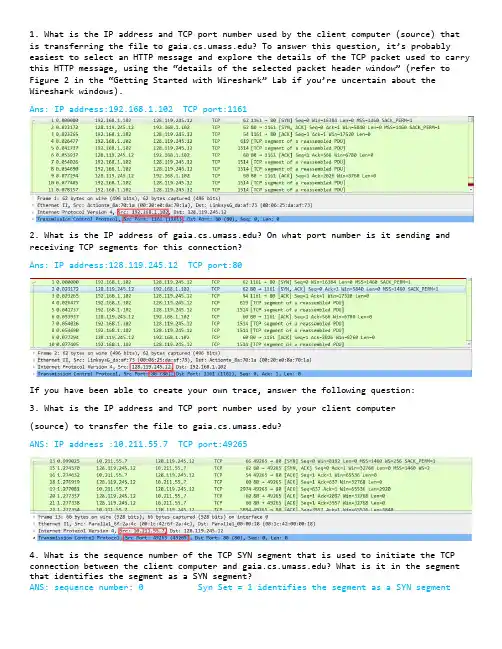
1. What is the IP address and TCP port number used by the client computer (source) that is transferring the file to ? To answer this questio n, it’s probably easiest to select an HTTP message and explore the details of the TCP packet used to carry this HTTP message, using the “details of the selected packet header window” (refer to Figure 2 in the “Getting Started with Wireshark” Lab if you’re uncertain about the Wireshark windows).Ans: IP address:192.168.1.102 TCP port:11612. What is the IP address of ? On what port number is it sending and receiving TCP segments for this connection?Ans: IP address:128.119.245.12 TCP port:80If you have been able to create your own trace, answer the following question:3. What is the IP address and TCP port number used by your client computer(source) to transfer the file to ?ANS: IP address :10.211.55.7 TCP port:492654. What is the sequence number of the TCP SYN segment that is used to initiate the TCP connection between the client computer and ? What is it in the segment that identifies the segment as a SYN segment?ANS: sequence number: 0 Syn Set = 1 identifies the segment as a SYN segment5. What is the sequence number of the SYNACK segment sent by to the client computer in reply to the SYN? What is the value of the ACKnowledgement field in the SYNACK segment? How did determine that value? What is it in the segment that identifies the segment as a SYNACK segment?ANS: The sequence number: 0ACKnowledgement number : 1 which is sequence number plus 1Both the sequence flag and the ACKnowledgement flag been set as 1, identifies the segment as SYNACK segment.6. What is the sequence number of the TCP segment containing the HTTP POST command? Note that in order to find the POST command, you’ll need to dig into the packet content field at the bottom of the Wireshark window, looking for a segment with a “POST” within its DATA field.Ans: The sequence number : 17. Consider the TCP segment containing the HTTP POST as the first segment in the TCP connection. What are the sequence numbers of the first six segments in the TCP connection (including thesegment containing the HTTP POST)? At what time was each segment sent? When was the ACK for each segment received? Given the difference between when each TCP segment was sent, and when its acknowledgement was received, what is the RTT value for each of the six segments? What is the EstimatedRTT value (see page 249 in text) after the receipt of each ACK? Assume that the value of the EstimatedRTT is equal to the measured RTT for the first segment, and then is computed using the EstimatedRTT equation on page 249 for all subsequent segments.Note: Wireshark has a nice feature that allows you to plot the RTT for each of the TCP segments sent. Select a TCP segment in the “listing of captured packets” window that is being sent from the client to the server. Then select: Statistics->TCP Stream Graph- >Round Trip Time Graph.Segment 1 Segment 2 Segment 3Segment 4Segment 5Segment 6After Segment 1 : EstimatedRTT = 0.02746After Segment 2 : EstimatedRTT = 0.875 * 0.02746 + 0.125*0.035557 = 0.028472 After Segment 3 : EstimatedRTT = 0.875 * 0.028472 + 0.125*0.070059 = 0.033670 After Segment 4 : EstimatedRTT = 0.875 * 0.033670 + 0.125*0.11443 = 0.043765 After Segment 5 : EstimatedRTT = 0.875 * 0.043765 + 0.125*0.13989 = 0.055781 After Segment 6 : EstimatedRTT = 0.875 * 0.055781 + 0.125*0.18964 = 0.072513 8. What is the length of each of the first six TCP segments?(see Q7)9. What is the minimum amount of available buffer space advertised at the received for the entire trace? Does the lack of receiver buffer space ever throttle thesender?ANS:The minimum amount of buffer space (receiver window) advertised at for the entire trace is 5840 bytes;This receiver window grows steadily until a maximum receiver buffer size of 62780 bytes.The sender is never throttled due to lacking of receiver buffer space by inspecting this trace.10. Are there any retransmitted segments in the trace file? What did you check for (in the trace) in order to answer this question?ANS: There are no retransmitted segments in the trace file. We can verify this by checking the sequence numbers of the TCP segments in the trace file. All sequence numbers are increasing.so there is no retramstmitted segment.11. How much data does the receiver typically acknowledge in an ACK? Can youidentify cases where the receiver is ACKing every other received segment (seeTable 3.2 on page 257 in the text).ANS: According to this screenshot, the data received by the server between these two ACKs is 1460bytes. there are cases where the receiver is ACKing every other segment 2920 bytes = 1460*2 bytes. For example 64005-61085 = 292012. What is the throughput (bytes transferred per unit time) for the TCP connection? Explain how you calculated this value.ANS: total amount data = 164091 - 1 = 164090 bytes#164091 bytes for NO.202 segment and 1 bytes for NO.4 segmentTotal transmission time = 5.455830 – 0.026477 = 5.4294So the throughput for the TCP connection is computed as 164090/5.4294 = 30.222 KByte/sec.13. Use the Time-Sequence-Graph(Stevens) plotting tool to view the sequence number versus time plot of segments being sent from the client to the server. Can you identify where TCP’s slow start phase begins and ends, and where congestion avoidance takes over? Comment on ways in which the measured data differs from the idealized behavior of TCP that we’ve studied in the text.ANS: Slow start begins when HTTP POST segment begins. But we can’t identify where TCP’s slow start phase ends, and where congestion avoidance takes over.14. Answer each of two questions above for the trace that you have gathered when you transferred a file from your computer to ANS: Slow start begins when HTTP POST segment begins. But we can’t identify where TCP’s slow start phase ends, and where congestion avoidance takes over.。
实验3:可靠数据传输协议-GBN协议的设计与实现
1.实验目的
理解滑动窗口协议的基本原理;掌握GBN的工作原理;掌握基于UDP设计并实现一个GBN协议的过程与技术。
2.实验环境
接入Internet的实验主机;
Windows xp或Windows7/8;
开发语言:C/C++(或Java)等。
3.实验内容
1)基于UDP设计一个简单的GBN协议,实现单向可靠数据传输(服务器到客户的数据传输)。
2)模拟引入数据包的丢失,验证所设计协议的有效性。
3)改进所设计的GBN协议,支持双向数据传输;
4.实验设计
1)Client:
函数列表:
各函数功能:
状态转换图:
2)Server:
状态转换图:
3)数据包结构:
发送方:数据包包括序列号与内容接收方:只含接收到的数据包的序号
5.实验结果1)Client:
2)Server:
详细对照:。
计算机网络实验报告(6篇)计算机网络实验报告(通用6篇)计算机网络实验报告篇1一、实验目的1、熟悉微机的各个部件;2、掌握将各个部件组装成一台主机的方法和步骤;3、掌握每个部件的安装方法;4、了解微型计算机系统的基本配置;5、熟悉并掌握DOS操作系统的使用;6、掌握文件、目录、路径等概念;7、掌握常用虚拟机软件的安装和使用;8、熟悉并掌握虚拟机上WINDOWS操作系统的安装方法及使用;9、掌握使用启动U盘的制作和U盘安装windows操作系统的方法;10、了解WINDOWS操作系统的基本配置和优化方法。
二、实验内容1.将微机的各个部件组装成一台主机;2.调试机器,使其正常工作;3.了解计算机系统的基本配置。
4.安装及使用虚拟机软件;5.安装WINDOWS7操作系统;6.常用DOS命令的使用;7.学会制作启动U盘和使用方法;8.WINDOWS7的基本操作;9.操作系统的基本设置和优化。
三、实验步骤(参照实验指导书上的内容,结合实验过程中做的具体内容,完成此项内容的撰写)四、思考与总结(写实验的心得体会等)计算机网络实验报告篇2windows平台逻辑层数据恢复一、实验目的:通过运用软件R-Studio_5.0和winhe_对误格式化的硬盘或者其他设备进行数据恢复,通过实验了解windows平台逻辑层误格式化数据恢复原理,能够深入理解并掌握数据恢复软件的使用方法,并能熟练运用这些软件对存储设备设备进行数据恢复。
二、实验要求:运用软件R-Studio_5.0和winhe_对电脑磁盘或者自己的U盘中的删除的数据文件进行恢复,对各种文件进行多次尝试,音频文件、系统文件、文档文件等,对简单删除和格式化的磁盘文件分别恢复,并检查和验证恢复结果,分析两个软件的数据恢复功能差异与优势,进一步熟悉存储介质数据修复和恢复方法及过程,提高自身的对存储介质逻辑层恢复技能。
三、实验环境和设备:(1)Windows _P 或Windows 20__ Professional操作系统。
实验:二层以太网组网和交换机的配置实验一:二层以太网组网实验【实验目的】1. 了解局域网各组成部分。
2. 掌握网络设备类型选择、软硬件设置方法。
3. 掌握基本的网络故障的判断、解决方法。
【实验环境】Cisco 2950交换机、具备Windows 操作系统的PC 机、直通双绞线、交叉双绞线。
【实验重点及难点】9 重点:学习网络设备的连接与设置方法。
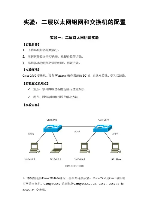
9 难点:网络故障的判断及解决方法【实验内容】网络连接示意图1、本实验选择Cisco 2950-24作为二层网络连接设备。
Cisco 2950是Cisco 最低端可网管交换机。
Catalyst 2950 系列包括Catalyst 2950T-24、2950-、2950-12 和2950C-24 交换机。
192.168.0.4 192.168.0.1 192.168.0.2 192.168.0.3 Cisco 2950 Cisco 2950Catalyst 2950-24 交换机有24 个10/100 端口;2950-12 有12 个10/100 端口;2950T-24 有24个10/100 端口和2 个固定10/100/1000 BaseT 上行链路端口;2950C-24 有24 个10/100 端口和2 个固定100 BaseFX 上行链路端口。
本次实验不考虑对交换机进行设计,只按照交换机的默认设置。
按照如上连接图进行网络连接。
具体连接过程如下:1)Cisco 2950交换机连接,将两台交换机接通电源,系统自检正常以后,任意选择两个交换机的端口,通过交叉线进行连接。
2)将如图PC机及笔记本加电,并通过直通线分别接入各交换机,观察各接入端口,待端口为绿色是为正常。
Cisco 2950交换机的端口在接入PC机时,其端口有30秒的测试过程,此过程中状态灯为黄色,若端口检测正常,则会转变为绿色。
在此步骤中思考以下问题:1)实验中Cisco 2950加电启动的过程?2)Cisco 2950交换机端口数是多少?3)Cisco 2950在接入设备时状态灯的变化过程。
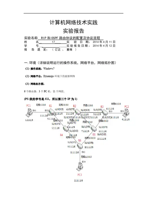
计算机网络技术实践实验报告实验名称 RIP和OSPF路由协议的配置及协议流程姓名__ 17____ 实验日期: 2014年4月11日学号___ _____实验报告日期: 2014年4月12日报告退发: ( 订正、重做 )一.环境(详细说明运行的操作系统,网络平台,网络拓扑图)(1)操作系统:Windows7(2)网络平台:Dynamips环境下的虚拟网络(3)网络拓扑图:6个路由器,3个PC机,11个网段。
(PS:我的学号是511,所以第三个IP为1)二.实验目的✧在上一次实验的基础上实现RIP和OSPF路由协议✧自己设计网络物理拓扑和逻辑网段,并在其上实现RIP和OSPF协议;✧通过debug信息来分析RIP协议的工作过程,并观察配置水平分割和没有配置水平分割两种情况下RIP协议工作过程的变化。
三.实验内容及步骤(包括主要配置流程,重要部分需要截图)(1)改写的.net文件(2)实现RIP和OSPF协议前配置1.运行各个路由器和主机2.完成各个路由器和主机端口配置R1端口:PC1端口:测试连通性:(3)实现RIP协议未配置RIP协议的情况:R1端口配置RIP:测试RIP后路由之间的联通:测试RIP后主机之间的联通:配置RIP协议的情况:Debug信息:R1路由:R2路由:同一自治系统中的路由器每过一段时间会与相邻的路由器交换子讯息,以动态的建立路由表。
RIP 允许最大的跳数为15 多于15跳不可达。
RIP协议根据距离矢量路由算法来完成。
每个路由器都有一个路由表,通过相互传递路由表来更新最新的与其他路由之间的信息。
从上图中R1路由是接收R2传来的信息来更新路由表,而R2是从R5接收信息来更新路由表。
关闭R2水平分割:通过对比关闭之前和之后的R2的debug信息,我们可以发现,在关闭之前,路由器会标记已经收到的信息,不会重复的接收和发出,而关闭之后路由器就在两个路由之间不停的循环发送和接收,照成了不必要操作。

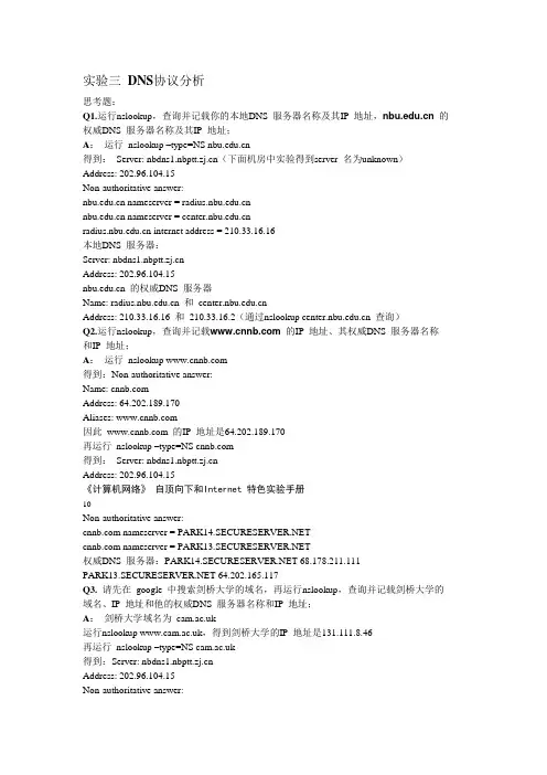
实验三DNS协议分析思考题:Q1.运行nslookup,查询并记载你的本地DNS 服务器名称及其IP 地址, 的权威DNS 服务器名称及其IP 地址;A:运行nslookup –type=NS 得到:Server: (下面机房中实验得到server 名为unknown)Address: 202.96.104.15Non-authoritative answer: nameserver = nameserver = internet address = 210.33.16.16本地DNS 服务器:Server: Address: 202.96.104.15 的权威DNS 服务器Name: 和Address: 210.33.16.16 和210.33.16.2(通过nslookup 查询)Q2.运行nslookup,查询并记载 的IP 地址、其权威DNS 服务器名称和IP 地址;A:运行nslookup 得到:Non-authoritative answer:Name: Address: 64.202.189.170Aliases: 因此 的IP 地址是64.202.189.170再运行nslookup –type=NS 得到:Server: Address: 202.96.104.15《计算机网络》自顶向下和Internet 特色实验手册10Non-authoritative answer: nameserver = nameserver = 权威DNS 服务器: 68.178.211.111 64.202.165.117Q3. 请先在google 中搜索剑桥大学的域名,再运行nslookup,查询并记载剑桥大学的域名、IP 地址和他的权威DNS 服务器名称和IP 地址;A:剑桥大学域名为运行nslookup ,得到剑桥大学的IP 地址是131.111.8.46再运行nslookup –type=NS 得到:Server: Address: 202.96.104.15Non-authoritative answer: nameserver = nameserver = nameserver = nameserver = nameserver = nameserver = nameserver = 其中权威服务器 internet address = 128.232.0.19Q4.运行ipconfig/all,查询并记载你的本地DNS 服务器,看和nslookup 显示的有无差别,如有差别差在哪里?为什么?A:本地DNS 服务器为202.96.104.15。
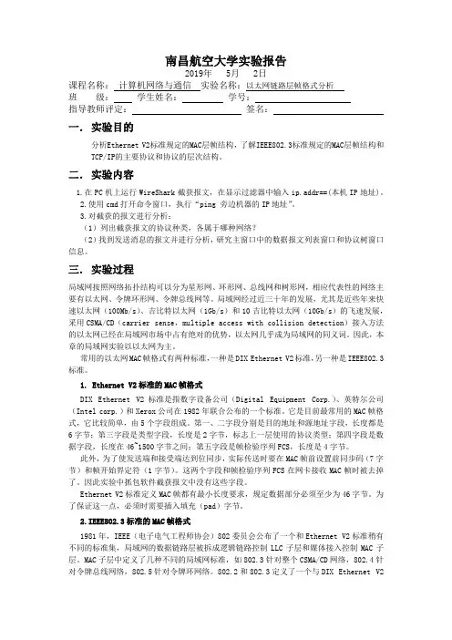
南昌航空大学实验报告2019年 5月 2日课程名称:计算机网络与通信实验名称:以太网链路层帧格式分析班级:学生姓名:学号:指导教师评定:签名:一.实验目的分析Ethernet V2标准规定的MAC层帧结构,了解IEEE802.3标准规定的MAC层帧结构和TCP/IP的主要协议和协议的层次结构。
二.实验内容1.在PC机上运行WireShark截获报文,在显示过滤器中输入ip.addr==(本机IP地址)。
2.使用cmd打开命令窗口,执行“ping 旁边机器的IP地址”。
3.对截获的报文进行分析:(1)列出截获报文的协议种类,各属于哪种网络?(2)找到发送消息的报文并进行分析,研究主窗口中的数据报文列表窗口和协议树窗口信息。
三.实验过程局域网按照网络拓扑结构可以分为星形网、环形网、总线网和树形网,相应代表性的网络主要有以太网、令牌环形网、令牌总线网等。
局域网经过近三十年的发展,尤其是近些年来快速以太网(100Mb/s)、吉比特以太网(1Gb/s)和10吉比特以太网(10Gb/s)的飞速发展,采用CSMA/CD(carrier sense,multiple access with collision detection)接入方法的以太网已经在局域网市场中占有绝对的优势,以太网几乎成为局域网的同义词。
因此,本章的局域网实验以以太网为主。
常用的以太网MAC帧格式有两种标准,一种是DIX Ethernet V2标准,另一种是IEEE802.3标准。
1. Ethernet V2标准的MAC帧格式DIX Ethernet V2标准是指数字设备公司(Digital Equipment Corp.)、英特尔公司(Intel corp.)和Xerox公司在1982年联合公布的一个标准。
它是目前最常用的MAC帧格式,它比较简单,由5个字段组成。
第一、二字段分别是目的地址和源地址字段,长度都是6字节;第三字段是类型字段,长度是2字节,标志上一层使用的协议类型;第四字段是数据字段,长度在46~1500字节之间;第五字段是帧检验序列FCS,长度是4字节。
计算机网络实验报告实验3一、实验目的本次计算机网络实验 3 的主要目的是深入理解和掌握计算机网络中的相关技术和概念,通过实际操作和观察,增强对网络通信原理、协议分析以及网络配置的实际应用能力。
二、实验环境本次实验在计算机网络实验室进行,使用的设备包括计算机、网络交换机、路由器等。
操作系统为 Windows 10,实验中使用的软件工具包括 Wireshark 网络协议分析工具、Cisco Packet Tracer 网络模拟软件等。
三、实验内容与步骤(一)网络拓扑结构的搭建使用 Cisco Packet Tracer 软件,构建一个包含多个子网的复杂网络拓扑结构。
在这个拓扑结构中,包括了不同类型的网络设备,如交换机、路由器等,并配置了相应的 IP 地址和子网掩码。
(二)网络协议分析启动 Wireshark 工具,捕获网络中的数据包。
通过对捕获到的数据包进行分析,了解常见的网络协议,如 TCP、IP、UDP 等的格式和工作原理。
观察数据包中的源地址、目的地址、协议类型、端口号等关键信息,并分析它们在网络通信中的作用。
(三)网络配置与管理在实际的网络环境中,对计算机的网络参数进行配置,包括 IP 地址、子网掩码、网关、DNS 服务器等。
通过命令行工具(如 Windows 中的 ipconfig 命令)查看和验证配置的正确性。
(四)网络故障排查与解决设置一些网络故障,如 IP 地址冲突、网络连接中断等,然后通过相关的工具和技术手段进行故障排查和解决。
学习使用 ping 命令、tracert 命令等网络诊断工具,分析故障产生的原因,并采取相应的解决措施。
四、实验结果与分析(一)网络拓扑结构搭建结果成功构建了包含多个子网的网络拓扑结构,各个设备之间能够正常通信。
通过查看设备的状态指示灯和配置信息,验证了网络连接的正确性。
(二)网络协议分析结果通过 Wireshark 捕获到的数据包,清晰地看到了 TCP 三次握手的过程,以及 IP 数据包的分片和重组。
实验三:路由器的配置评分标准若实验报告每一项内容基本达到以下要求则可评为80分,95分封顶,实验报告总分为:实验过程及结果得分*80%+实验总结*20%。
一旦发现抄袭现象,则总分一律评为50分以下。
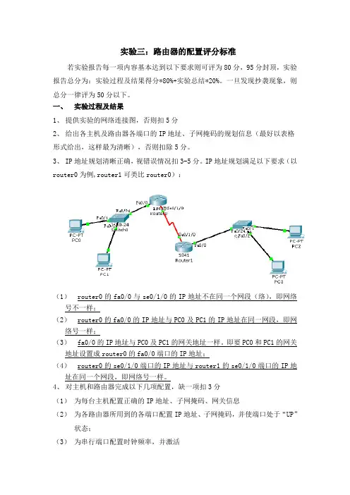
一、实验过程及结果1、提供实验的网络连接图,否则扣5分2、给出各主机及路由器各端口的IP地址、子网掩码的规划信息(最好以表格形式给出,这样最为清晰),否则扣除5分。
3、IP地址规划清晰正确,视错误情况扣3-5分。
IP地址规划满足以下要求(以router0为例,router1可类比router0):(1)router0的fa0/0与se0/1/0的IP地址不在同一个网段(络),即网络号不一样;(2)router0的fa0/0的IP地址与PC0及PC1的IP地址在同一网段,即网络号一样;(3)fa0/0的IP地址与PC0及PC1的网关地址一样。
即要PC0和PC1的网关地址设置成router0的fa0/0端口的IP地址;(4)router0的se0/1/0端口的IP地址与router1的se0/1/0端口的IP地址在同一个网段,即网络号一样。
4、对主机和路由器完成以下几项配置,缺一项扣3分(1)为每台主机配置正确的IP地址、子网掩码、网关信息(2)为各路由器所用到的各端口配置IP地址、子网掩码,并使端口处于“UP”状态;(3)为串行端口配置时钟频率,并激活(4)为各路由器配置路由信息协议(RIP)(5)使用show ip route查看路由器的路由表情况,并解释5、路由器的各项配置均有配置过程截图(只保留有用和正确的部分,图片文字能看的清,大小缩放合适)或文字形式的详细的配置命令。
若配置命令不完全、存在错误,视缺失和错误情况酌情扣3-6分6、对截图或配置过程进行必要的文字说明(忌啰嗦),即交代实验原理、思路、实验设计的想法等。
否则酌情扣2-3分6、有实验结果验证及说明,否则扣5分7、实验过程阐述思路清晰,有调理。
实验三交换机的配置及VLAN背景资料:一、Cisco CLI的命令模式1. 用户执行模式Switch>2. 特权执行模式Switch#3. 全局配置模式Switch(config)#4. 特定配置模式Switch(config-if/vlan/…)二、交换机的基本配置Switch>enable (进入特权执行模式)Switch#configure terminal(进入全局配置模式)Switch(config)#hostname 提示符名称(配置交换机名称,例如SW)Switch(config)#enable secret ****** (配置交换机特权模式的密文密码)Switch(config)#enable pssword ******(配置交换机特权模式的明文密码)Switch(config[-if/…])#exit (逐级退出,特定配置模式->全局配置模式->特权执行模式->用户执行模式)Switch(config)#end (直接退到特权模式)****#^Z (退到特权执行模式)--More--表示还有内容显示,此时,空格:翻页显示;回车:按行显示。
三、创建和删除VLAN1. 生成vlan 10和vlan 20Switch>enableSwitch#configure terminalSwitch(config)#vlan 10Switch(config-vlan)#name test10Switch(config-vlan)#endSwitch#configure terminalSwitch(config)#vlan 20Switch(config-vlan)#name test20Switch(config-vlan)#endSwitch#show vlan2. 删除vlan 10和vlan 20Switch>enSwitch#conf tSwitch(config)#no vlan 10Switch(config)#endSwitch#conf tSwitch(config)#no vlan 20Switch(config)#endSwitch#show vlan brief四、在VLAN中添加和删除端口1.把交换机F0/1端口分配到VLAN 10中Switch>enSwitch#conf tSwitch(config)#interface f0/1Switch(config-if)#swichport mode accessSwitch(config-if)#switchport access vlan10Switch(config-if)endSwitch#show interface f0/1 switchport2.把交换机F0/1端口从VLAN 10中删除Swtich>enSwitch#conf tSwitch(config)#interface f0/1Switch(config-if)#no switchport access vlan 10Switch(config-if)#endSwitch#show vlan brief一、实验任务掌握划分交换机VLAN的基本方法。
实验3北航研究生计算机网络实验引言:计算机网络是现代社会中不可或缺的一部分,实验3是北航研究生计算机网络实验课程中的一部分。
该实验旨在帮助学生深入理解计算机网络的工作原理,并通过实践操作加深对计算机网络的理解。
实验目的:1. 了解计算机网络的基本原理和概念;2. 掌握计算机网络的实验环境和工具;3. 实践操作计算机网络的基本配置和管理。
实验内容:1. 实验环境的搭建:搭建一个基于模拟器的计算机网络实验环境,如使用 GNS3 或 Packet Tracer 软件进行网络拓扑的设计与配置;2. 网络配置与管理:配置网络设备,如路由器、交换机等,并实现网络互连与通信;3. 网络协议的配置与测试:配置网络协议,如TCP/IP协议,并进行相应的测试与验证。
实验步骤:1. 实验环境的搭建:a. 选择合适的计算机网络模拟器软件,如 GNS3 或 Packet Tracer;b. 安装所选软件,并进行基本配置;c. 设计一个适合的网络拓扑并配置网络设备。
2. 网络配置与管理:a. 配置路由器和交换机以实现网络设备的互连;b. 设置网络设备的IP地址,子网掩码等;c. 配置路由表以实现数据包转发;d. 测试网络连接和通信是否正常。
3. 网络协议的配置与测试:a. 选择合适的网络协议,如TCP/IP协议;b. 配置所选协议的相关参数,如IP地址、子网掩码、网关等;c. 测试配置是否正确,如通过 ping 命令测试是否能够与其他主机进行通信;d. 验证网络协议在正常工作情况下的特性,如TCP的可靠数据传输、IP的数据路由等。
实验总结与心得:通过完成实验3,我对计算机网络的工作原理和实现有了更深入的了解。
实验中,我通过搭建实验环境和配置网络设备,学会了如何建立和管理一个基本的计算机网络。
我还通过配置和测试网络协议,掌握了常用协议的配置和测试方法,并对协议在实际网络中的应用有了更好的理解。
在实验过程中,我遇到了一些挑战,如网络设备的设置和网络连接的调试。
计算机网络技术实验3实验目的:1. 理解计算机网络中数据包的传输过程。
2. 掌握使用网络分析工具(如Wireshark)捕获和分析网络数据包。
3. 学习网络协议的基本概念和工作机制。
实验环境:1. 计算机若干台,每台计算机均安装有操作系统(如Windows或Linux)。
2. 网络分析工具Wireshark。
3. 网络连接设备,如路由器、交换机等。
4. 网络线缆,确保计算机之间可以进行网络连接。
实验步骤:1. 网络环境搭建:- 连接计算机至路由器,确保所有计算机处于同一局域网内。
- 配置计算机的IP地址,确保它们在同一子网中。
2. 安装并配置Wireshark:- 在每台计算机上安装Wireshark软件。
- 打开Wireshark,选择适当的网络接口进行捕获设置。
3. 数据包捕获:- 启动Wireshark,开始捕获网络流量。
- 在另一台计算机上进行网络活动,如浏览网页、发送邮件等。
4. 数据包分析:- 观察Wireshark捕获的数据包,注意数据包的类型、大小、源地址和目的地址等信息。
- 使用Wireshark的过滤功能,筛选特定的数据包,如HTTP请求、TCP三次握手等。
5. 协议分析:- 选择一个TCP/IP数据包,分析其头部信息,包括序列号、确认号、窗口大小等。
- 观察TCP三次握手过程,理解其在建立连接中的作用。
6. 网络故障模拟与诊断:- 人为制造一些网络故障,如断开网络连接、修改IP地址等。
- 使用Wireshark观察故障发生时的数据包变化,分析故障原因。
7. 实验报告撰写:- 记录实验过程中的关键步骤和观察结果。
- 分析数据包捕获和分析的结果,总结网络协议的工作原理。
- 讨论网络故障模拟与诊断的过程和结果。
实验注意事项:- 在进行网络故障模拟时,确保不会对实验环境造成不可逆的损害。
- 在使用Wireshark时,注意遵守相关法律法规,不得用于非法监听或侵犯他人隐私。
- 实验过程中,注意记录详细的数据包信息,以便于后续分析。
计算机网络实验三
仲恺农业工程学院实验报告纸
自动化(院、系)自动化专业 122 班___ 组计算机通信网课
实验三虚拟局域网VLAN
第一部分:交换机端口隔离.
【实验名称】
交换机端口隔离.
【实验目的】
理解Port Vlan的配置,了解VLAN的原理,熟练掌握交换机端口隔离划分虚拟局
【背景描述】
假设此交换机是宽带小区城域网中的一台楼道交换机,住户PC1连接在交换机的
fa0/5口;住户PC2连接在交换机的fa0/15口,住户pc3连接在fa0/1口.现要实现各家各户
的端口隔离.
【实现功能】
通过PORT VLAN实现本交换机端口隔离. (通过虚拟局域网技术可以隔离网络风暴,
提高网络的性能,降低无用的网络开销。
并能提高网络的安全性,保密性。
)
【实现拓扑】
Switch PC1 PC2
【实验设备】
S2126G 1台、PC机
【实验步骤】
步骤1.搭建一个小型局域网的拓扑,使得一台可网管的交换机,通过普通快速以太
网端口f0/1、f0/2、f0/10与多台PC,使用直连线相连接。
并给三台PC机配置IP,要求所有IP属于同一个网段。
保证三台PC两两之间互相能够ping通。
截图于此
switchA#configure terminal !进入交换机全局配置模式
switchA(config)#vlan 2 !创建VLAN2
switchA(config-vlan)#name wxk01 !将其命名为wxk01
switchA(config-vlan)#exit!退出VLAN 01
switchA(config)#vlan 3 !创建VLAN 02
switchA(config-vlan)#name wxk02 !将其命名为wxk02
switchA(config-if)#exit
验证测试
使用命令show vlan和show running-config查看与刚才有何不同。
switchA#show vlan
步骤2.将接口分配到VLAN.
switchA(config)#interface fa0/1 !进入fa0/1的接口配置模式。
switchA(config-if)#switch mode access
switchA(config-if)#switch access vlan 2 !将fa 0/1 端口加入VLAN 2中。
switchA(config-if)#exit
switchA(config)#interface fa 0/2 !进入fa0/2的接口配置模式。
switchA(config-if)#switch mode access
switchA(config-if)#switch access vlan 3 !将fa 0/2 端口加入VLAN 3中。
switchA(config-if)#exit
验证测试
switchA#show vlan
步骤3.测试任两台PC互相PING不通.
第二部分:跨交换机实现VLAN
【实验名称】
跨交换机实现VLAN.
【实验目的】
理解VLAN如何跨交换机实现.
【背景描述】
假设某企业有2个主要部门:销售部和技术部,其中销售部门的个人计算机系统
分散连接在2台交换机上,他们之间需要相互连接通信,但为了数据安全起见,销
售部和技术部须要进行相互隔离,现要在交换机上做适当配置来事项这一目标.
【实现功能】
Port VLAN 来实现交换机的端口隔离,然后使在同一个VLAN里的计算机系统
能跨交换机进行相互通信,而在不同VLAN里的计算机不能进行相互通信。
.
【实验拓扑】
【实验步骤】(设置PC0的IP为192.168.0.17,PC1的IP为192.168.0.18,PC2的IP为192.168.0.19)
步骤1. 在交换机Switch2上创建VLAN 02 VLAN 03 ,并将f0/5端口划分到VLAN02中. 并将f0/15端口划分到VLAN03中
Switch2#configure terminal !进入全局配置模式
Switch2(config)#vlan 02 !创建VLAN02
Switch2(config-vlan)#interface fa 0/5 !进入接口配置模式。
Switch2(config-if)#switch mode access
Switch2(config-if)#switchport access vlan 02 !将f0/5端口划分到VLAN 02中Switch2(config-if)#exit
Switch2(config)#vlan 03 ! 创建VLAN03
Switch2(config-vlan)#interface f 0/15 !进入接口配置模式
Switch2(config-if)#switch mode access
Switch2(config-if)#switchport access vlan 03 !将f0/15端口划分到VLAN 03中验证测试:验证已创建了VLAN 02,并将f0/5端口已划分到VLAN 02中。
验证已创建了VLAN 03,并将f0/15端口已划分到VLAN 03中。
Switch2#show vlan
步骤2.在交换机Switch1上创建VLAN01,并将f0/5端口划分到VLAN 01 中.
Switch1#configure terminal !进入全局配置模式
Switch1(config)#vlan 01 !创建VLAN01
Switch1(config-vlan)#name sales !将其命名为sales.
Switch1(config-vlan)#exit
Switch1(config)#interface fa 0/5 !进入接口配置模式。
Switch1(config)#switch mode access
Switch1(config-if)#switchport access vlan 01 !将f0/5端口划分到VLAN 01中Switch1(config-if)#exit
Switch1(config)#exit
Switch1#show vlan
验证测试:验证已创建了VLAN 01,并将f0/35端口已划分到VLAN 01中。
步骤3.在交换机Switch1上将与Switch2相连的端口定义为tag vlan 模式.
Switch1(config)#interface fa 0/24 !进入接口配置模式
Switch1(config-if)#switchport mode trunk !将fa0/24端口设为tag vlan模式。
Switch1(config-if)#exit
Switch1(config)#exit
验证测试:验证fa 0/24端口已被设置为tag vlan 模式。
Switch1#show interfaces fa 0/24 switchport
步骤4.在交换机Switch2上将与Switch1相连的端口定义为tag vlan模式.
Switch2(config)#interface fa 0/3 !进入接口配置模式
Switch2(config-if)#switchport mode trunk !将fa0/3端口设为tag vlan模式。
Switch2(config-if)#exit
Switch2(config)#exit
验证测试:验证fa 0/3端口已被设置为tag vlan 模式。
Switch2#show interfaces fa 0/3 switchport
步骤5.验证PC0与PC1能互相通信,但PC0与PC2不能互相通信.
PC:\ping 192.168.0.18
PC:\ping 192.168.0.19
【注意事项】
1.丄台交换机之间相连的端口应该设置为tag vlan 模式.
2.两台交换机之间的端口应该设置为tag vlan
的传输。
3. Trunk接口在默认情况下支持所有vlan
【实验心得】
通过此次实验,理解Port Vlan的配置,了解VLAN的原理,熟练掌握交换机端口隔离划分虚拟局;理解VLAN如何跨交换机实现。
实验可能一开始是没有结果的,不过要不断
排查问题所在,还要充分利用身边的资源,团队
合作很重要,耐心也是很重要的。
持之以恒才能
得到最终的结果,可能一开始觉得找不到什么解决方法,可能峰回路转就会得到你想要的结果。