RAMC 浮子流量计 中文说明书
- 格式:pdf
- 大小:914.92 KB
- 文档页数:19

1前言非常感谢您选择丹东通博电器(集团)有限公司的产品。
MTF 型智能金属管浮子流量计已获1项外观专利,专利号:ZL02 3 53133.9.MTF 型智能金属管浮子流量计已通过国家防爆认证,认证标志:Exia ⅡCT4,Exd ⅡCT4。
使用前请仔细阅读使用说明书,特别是与防爆相关的环境温度等各项要求。
2概述a) 本产品执行标准代号:Q/AMM 014-2010;b) 产品特点:MTF 型智能金属浮子流量计是我公司研制开发的智能系列仪表,是模拟、数字与微处理器相结合的产品。
该流量计将流体流量信号变换为对应模拟电压信号并转换成4~20mA 两线制电流输出并且加载HART 协议通讯,具有高精度,低漂移,抗干扰能力强等特点。
并可以实现对仪表的远程组态、监测、维护、及校准等功能。
可构成生产过程测量、监督管理系统。
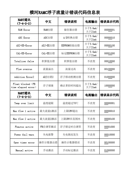
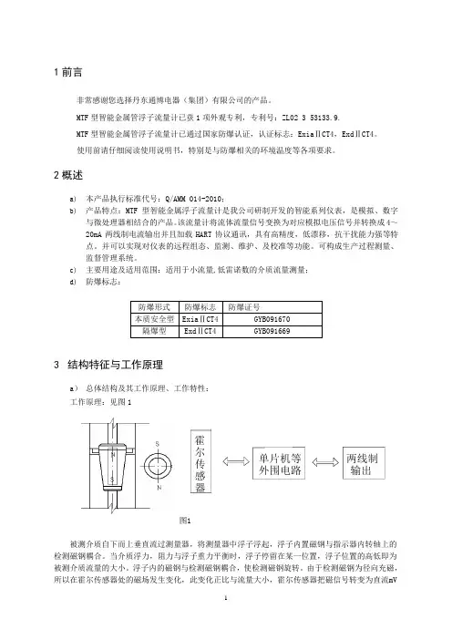
c) 主要用途及适用范围:适用于小流量,低雷诺数的介质流量测量; d) 防爆标志:3 结构特征与工作原理a ) 总体结构及其工作原理、工作特性:工作原理:见图1图1被测介质自下而上垂直流过测量器,将测量器中浮子浮起,浮子内置磁钢与指示器内转轴上的检测磁钢耦合。
当介质浮力,阻力与浮子重力平衡时,浮子停留在某一位置,浮子位置的高低即为被测介质流量的大小。
浮子内的磁钢与检测磁钢耦合,使检测磁钢旋转。
由于检测磁钢为径向充磁,所以在霍尔传感器处的磁场发生变化,此变化正比与流量大小,霍尔传感器把磁信号转变为直流mV防爆形式 防爆标志 防爆证号 本质安全型 Exia ⅡCT4 GYB091670 隔爆型 Exd ⅡCT4 GYB091669 器单片机等 外围电路 两线制 输出 尔传感霍信号,经单片机处理,输出两线制(4-20)mA电流信号并加载符合HART协议通讯的数字信号。
总体结构:流量计主要由测量器和指示器两大部分组成,按连接方式的不同可分为垂直安装和水平安装两种,如图2、图3所示图2垂直式式安装图3水平式安装b) 主要部件或功能单元的结构、作用及其工作原理:测量器部分基本型:全部零件均由304制造,适用于液体测量。
使用手册Instruction manual安徽运诚科技集团有限公司2019.06 版金属管 浮子流量计应运而生因诚而存EMERGE AS THE TIMES REQUIREDEVELOPMENT BASED ON INTEGRITY金属管浮子流量计01概述金属管浮子流量计(金属管转子流量计)是工业自动化过程控制中常用的一种变面积流量测量仪表。
它具有体积小,检测范围大,使用方便等特点,它可用来测量液体、气体以及蒸汽的量,特别适宜低流速小流量的测量。
多年来,金属管浮子流量计以其优良性能和可靠性,以及较好的性能价格比,在石化、钢铁、电力、冶金、轻工、食品、制药、水处理等行业得到了广泛的应用。
本手册面向专业技术人员,适用于金属管浮子流量计的设计选型,也可用于最终用户在使用时的参考。
手册分别介绍了本系列金属管浮子流量计的工作原理、功能特点、技术参数、仪表类型及外形、流量计算、接线方法和安装、维护等。
本手册只针对本系列金属管浮子流量计的设计选型和使用,同时厂家保留某些技术参数改进而不预先通知的权利。
02测量原理本系列金属管浮子流量计主要由两大部分组成:传感器和指示器。
传感主要由连接法兰、测量锥管、浮子和上下导向器组成;指示器主要由壳体、磁传动系统、刻度盘和电远传系统组成。
在垂直的锥形测量管内,有一可上下移动的测量部件——浮子(图1),当流体自下而上通过锥形管时,浮子受到流体的作用力,沿锥形管向 上移动。
当流体的流量增大时,浮子的位移量增大;反之,流体的流量减少时,浮子的位移量变小。
也就是说,流体流量的大小,决定了浮子在测量管中的位置,从而决定了浮子和锥形管之间环形面积的大小。
当流体的流量保持在一个恒定的流量Q时,浮子也处于一动平衡状态,停留在锥形管中的一位置h,此时,浮子和锥形管之间的环形面积保持恒定。
浮子受到三个力的作用:浮子的重力G,浮子受到的浮力F,浮子受到流体的作用力P,这三个力达到平衡。
根据流体动力学的柏努力方程、力平衡原理和流体连续性定律,可以计算出此时通过环形面积的瞬时流体流量,所以,金属管浮子流量计是采用可变面积测量流量的原理。
MeasureMent and control technology.Flow Meter.Heat Requirement CalculationsAsahi/America, Inc.35 Green StreetMalden, MA 02148Phone: (800) 343-36184Float-typeflow meterFloat-type flow meterKey to symbols▲ PA (polyamide Trogamid)■ PSU (polysulphone)● PVC◆ PMMA (polymethylmethacrylate “Plexiglas”)Va 1.4571Tg Malleable cast iron5Flow meter M 335 / M 350Flow meter M 335 / M 350Measuring ranges 50 – 60,000 l/hFunction The FRANK flow meter M 335 / M 350 operates on the float principle and is used for flow rate measurements in closed pipelines. The medium flows through the vertically installed flow meter from bottom to top. This raises the float and shows the current flow rate on the scale on the measuring device. The read-off edge corresponds to the largest diameter of the float.FRANK M 335 / M350 flow meters come as standard with a water scale and a % scale, and two setpoint indicators.Special features:• Fracture-proof and corrosion-resistant • Radially removable• Special adhesive scales for liquid and gaseous media• Holder for accessories (limit value contacts)• Measuring tube carries the DN label, and also the measuring range and material • PVDF floats and stops as standard• Measuring ranges 50 – 60,000 l/h6Flow meterM 335 / M 350 Operating pressure: max. PN 10 at 20 °C* o nly with PVDF screw connectionFlow meter M 335 / M350Flow meter M 335 / M 3509Flow meter M 335 / M35010Flow meter M 335 / M 350Special scales as requested by the customer Details required: Medium, spec. weight in g/cm3, viscosity in cP or mPas, operating temperature in °C, desired measuring range in l/h.Application instructions for special scalesWhen applying special scales later, ensure that the marking ▼ on the scale corresponds with the one on the measuring tube.11Flow meter M 335 / M 350Accessories Limit value contact Z 40 min.Limit value contact Z 42 max.For further information, refer to the separate data sheets.Installation and assembly instructions • I nstall the flow meter into the pipeline system vertically and without tension.• P rovide an inlet and outlet section, Inlet approx. 10 x DN, outlet approx. 5 x DN.This table is used to correct values displayed for gases by the flow meter if the operating pressure deviates from the pressure used as a basis for the calibration. The values displayed on the flow meter are simply multiplied by the factor corresponding to the operating pressure.We supply special scales for operating pressures of between 1 and 8 bar (see Page 10).Notes on operation• A void pressure surges, as these can damage the unit.• E xercise caution when installing. The measuring tube must not come into contact with solvent.• B efore start-up, make sure that the connected parts are sufficiently tightened.• T he union nuts must not be mixed up on a measuring tube made from the material PVDF . The overall length also does not correspond to the dimensions table.We reserve the right to make technical changes in the interest of improvement.12Flow meter M 123Flow meter M 123Measuring ranges 15 – 1,000 l/h Function The FRANK M 123 flow meter works on the float principle and is used to measure the flow rate in closed pipelines. The medium flows through the vertically installed flow meter from bottom to top. This raises the float and shows the current flow rate on the scale on the measuring device. The read-off edge corresponds to the largest diameter of the float.FRANK M 123 flow meters have a water scale and 2 setpoint indicators as standard.Special features:• Fracture-proof and corrosion-resistant • Radially removable • A dhesive special scales, for liquid and gaseous media • Holder for accessories (limit value contacts)• Measuring tube carries the DN label, and also the measuring range and material • PVDF floats and stops as standard • Measuring ranges 1.5 – 1,000 l/h • Less space required thanks to short overall length13Flow meter M123Operating pressure: max. PN 10 at 20 °C14Flow meter M 123Screw connection with fusion spigot Screw connection with threaded socket15Flow meter M12316Flow meter M 123Special scales as requested by the customer Details required: Medium, spec. weight in g/cm3, viscosity in cP or mPas, operating temperature in °C, desired measuring range in l/h.Application instructions for special scalesWhen applying special scales later, ensure that the marking ▼ on the scale corresponds with the one on the measuring tube.AccessoriesLimit value contact Z 40Limit value contact Z 42Installation and assembly instructions• I nstall the flow meter into the pipeline system vertically and without tension.• P rovide an inlet and outlet section Inlet approx. 10 x DN, outlet approx. 5 x DN.Notes on operation• A void pressure surges, as these can damage the unit.• E xercise caution when installing. The measuring tube must not come into contact with solvent.• B efore start-up, make sure that the connected parts are sufficiently tightened.• T he union nuts must not be mixed up on a measuring tube made from the material PVDF. The overall length also does not correspond to the dimensions table.We reserve the right to make technical changes in the interest of improvement.17Limit value contact Z 40 min., Z 42 max.18Flow meterM 10 to M 13PMMA flow meter M 10 to M 13Measuring ranges 1.5 – 100 l/h H2OFunctionFRANK M 10 to M 13 flow meters work on the float principle and are used to measure the flow rate in closed pipelines. The medium flows through the vertically installed flow meter from bottom to top. This raises the float and shows the current flow rate on the scale on the measuring device. The read-off edge corresponds to the largest diameter of the float (ball).Operating pressure: max 10 bar at 20 °C Special features:• Compact and robust design• Short overall length• With needle valve (M10 and M 13), very fine adjustment19Flow meter M 10 to M13FRANK plastic AGHerbert-Frank-Straße 26D-72178 Waldachtal Telefon +49 (0) 7486 181 0Fax +49 (0) 7486 181 337 E-Mail info@frankplastic.de www.frankplastic.de。
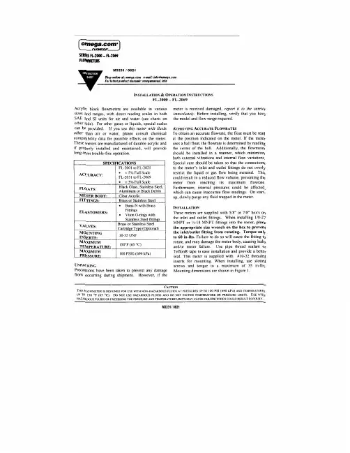
CLEAN ING AND DISASSEMBLY Occasional cleaning may be required if dirt appears in the flow tube or if float movement becomes restricted. To clean, remove the top plug and remove the float. Wash the tapered hole and top plug with a mild liquid detergent and soft brush. Rinse all parts with clean water and dry thoroughly with clean air or nitrogen. Do not use solvents to clean this meter as they will attack the acrylic and destroy the meter. FL-2001 FL-2031 FL-2060 DIMENSIONSto to to FL-2025 FL-2057 FL-2069 AIN. 4 6½6 5/8 mm 102 165 164 B IN. 3 5 1/i 5 In mm76.2 140 140 CIN. I I 318 I 1/8 mm 25.1 34.9 28.6 DIN. I 518 3½ 3 1/, mm 41.3 88.9 38.1 EIN. I 3/16 I 1/2 1112 mm 30.2 38.1 38.1 FIN. I 1/8 I 1/8 I 3/8 mm �9.6 28.6 34.9 G IN. 1/8-27 118-27 1/4-18 mm MNPT MNPT MNPT*Does not include 1 /8" backplate.FL-2001 to FL-2025 FLOW RATES RANGEMODEL RANGE MODEL SCFH OF A IRCODE LPM OF A IR CODE .1-1 rL-2001 .04 Lu o_s LMP FL-2010 .2-2 FL-2002 1-1 FL-2011 4-5 FL-2003 2-25 FL-2012 5-10 FL-2004 4-5 FL-2013 2-20 FL-2005 1-10 FL-2014 3.-30 FL-2006 2-25 FL-2015 4-50 FL-2007 6-50 FL-2016 10-100 FL-2008 10-100 F L -2017 20-200 GPHOFWATER CODE CCM OFWATER CODE 2-2 FL-2021 5-50 FL-2018 .4-5 FL-2022 10-100 FL-2019 1-IO FL-2023 20-240 FL-2020 2-20 FL-2024 4--40 FL-2025 RE-ASSEMBLY Check to make sure that all parts are clean and dry. To lubricate the o-rings, apply a small amount of halocarbon grease prior to re-assembly. If applicable, reinstall the rod guide assembly into the flowmeter body. Make sure the rod guide is seated firmly in the body of the meter. Reinstall the top plug, making sure that the rod guide is properly aligned. Tighten top plug until it's flush with top of acrylic body. Exceeding this may damage the meter body. If you have any questions regarding the installation, maintenance or use of this tlowmeter, please call the Customer Service Department. 1 ' / i'. -G .,, I0-32ME.ADED INSERTS (2PtACES) I 0 l @'. __ L 0 j i l---c-----i FL-2060 to FL-2069 F LOW RA T ES* RANGE MODEL RANGE MODEL SCF M OF AIR CODE LPM OF A IR CODE .5-5 FL-2060 14-140 FL-2063 1-10 FL-2061 30-280 FL-2064 2-20 FL-2062 60-560 FL-2065 GPM OFWATER CODE LPM OFWATER CODE .2-2.5 FL-2066 8-9 FL-2068 .4-5 FL-2067 1.5-20 FL-2069 FL-203 I to FL-2057 F LOW RA T ES RANGE MODEL RANGE MODEL SCF H O F A IR CODE CCM OFWATER CODE .4.5 FL-2031 4-50 FL-2045 1-10 FL-2032 10-120 FL-2046 2-20 FL-2033 25-225 FL-2047 4-40 FL-2034 40-400 FL-2048 10-100 FL-2035 40-060 FL-2049 14-150 FL-2036 100-1500 FL-2050 20-200 FL-2037200-3000 FL-2051 CCM OF A IR CODE ]00-3700 FL-2052 100-1000 FL-2038GPHWATER CODE LPM OF AIR CODE 1-10 FL-2053 .4-5 FL-2039 2-25 FL-2054 1-10 FL-2040 4-50 FL-2055 2-20 FL-2041 6-60 FL-2056 3-30 FL-2042 SCF M OF A IR CODE4-50 FL-2043 .3-3 FL-2057 10-100 FL-2044 CONTINUED PRODUCT IMPROVEMENT MAY RESULT IN SPECIFICATION REVISIONSWHEN ORDER.ING PARTS PLEASE tNCLUOE PART DESCRlPTtON. ITEM NUMBER AND TYPE OF MATERIAL REQUlRED.M3231 I 0821。

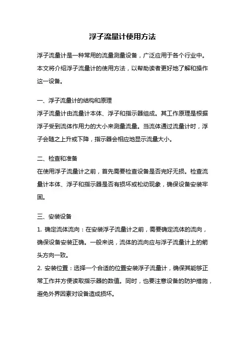
浮子流量计使用方法浮子流量计是一种常用的流量测量设备,广泛应用于各个行业中。
本文将介绍浮子流量计的使用方法,以帮助读者更好地了解和操作这一设备。
一、浮子流量计的结构和原理浮子流量计由流量计本体、浮子和指示器组成。
其工作原理是根据浮子受到流体作用力的大小来测量流量。
当流体通过流量计时,浮子会随之上升或下降,指示器会相应地显示流量大小。
二、检查和准备在使用浮子流量计之前,首先需要检查设备是否完好无损。
检查流量计本体、浮子和指示器是否有损坏或松动现象,确保设备安装牢固。
三、安装设备1. 确定流体流向:在安装浮子流量计之前,需要确定流体的流向,确保设备安装正确。
一般来说,流体的流向应与浮子流量计上的箭头方向一致。
2. 安装位置:选择一个合适的位置安装浮子流量计,确保其能够正常工作并方便读取指示器的数值。
同时,也要注意设备的防护措施,避免外界因素对设备造成损坏。
四、校准浮子流量计在使用浮子流量计之前,需要进行校准,以确保其测量的准确性。
校准浮子流量计的方法有多种,可以根据具体的设备和要求来选择适合的方法。
五、操作流程1. 打开阀门:在测量之前,需要打开流体流动的阀门,确保流体能够顺利通过浮子流量计。
2. 观察指示器:当流体通过流量计时,浮子会受到流体作用力的影响而上升或下降。
此时,可以观察指示器上的刻度,读取流量数值。
3. 记录数据:根据指示器上的刻度,记录流量数值。
可以根据需要选择手动记录或使用数据采集系统进行自动记录。
4. 关闭阀门:测量结束后,需要关闭流体流动的阀门,停止流体通过浮子流量计。
六、注意事项1. 清洁维护:定期对浮子流量计进行清洁和维护,确保设备的正常运行和准确测量。
2. 防止堵塞:避免流体中含有颗粒物质,以防止浮子流量计的堵塞。
3. 防止震动:在安装设备时,要注意避免设备受到震动或振动,以免影响测量结果的准确性。
4. 定期校准:定期对浮子流量计进行校准,以确保测量结果的准确性和稳定性。
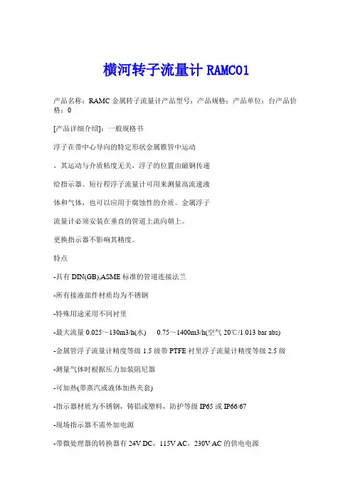
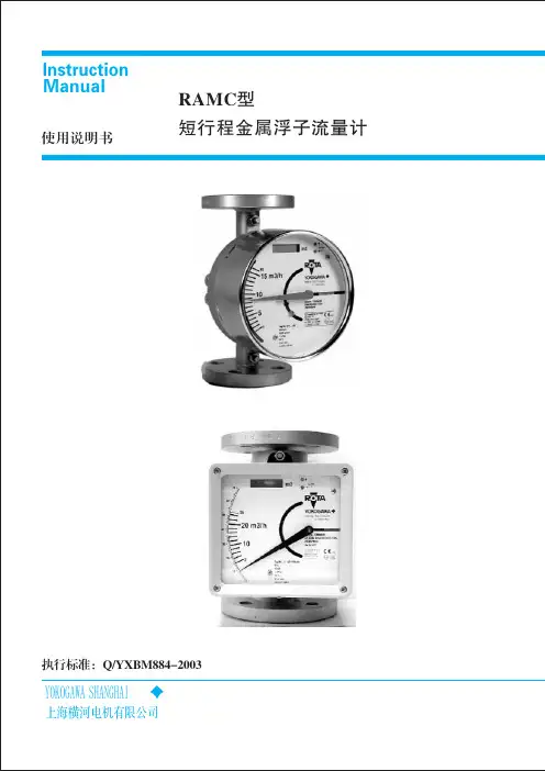
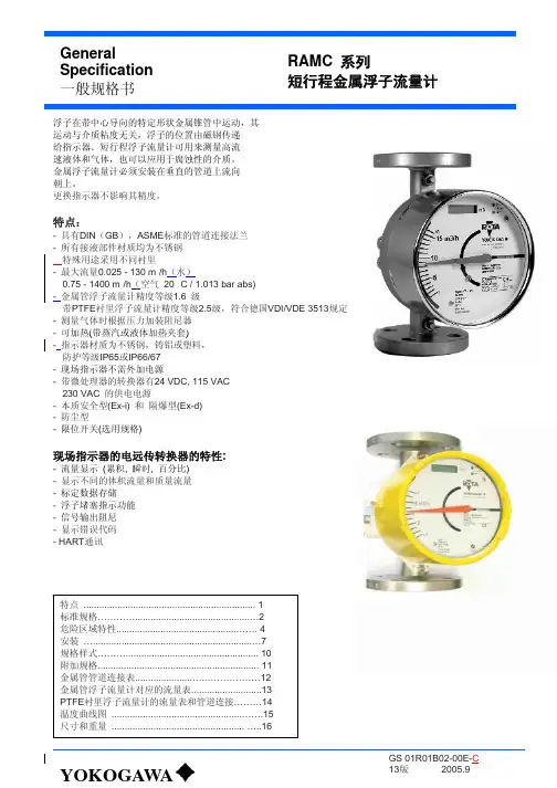
横河转子流量计RAMC01产品名称:RAMC金属转子流量计产品型号:产品规格:产品单位:台产品价格:0[产品详细介绍]:一般规格书浮子在带中心导向的特定形状金属锥管中运动,其运动与介质粘度无关,浮子的位置由磁钢传递给指示器。
短行程浮子流量计可用来测量高流速液体和气体,也可以应用于腐蚀性的介质。
金属浮子流量计必须安装在垂直的管道上流向朝上。
更换指示器不影响其精度。
特点-具有DIN(GB),ASME标准的管道连接法兰-所有接液部件材质均为不锈钢-特殊用途采用不同衬里-最大流量0.025~130m3/h(水) 0.75~1400m3/h(空气20℃/1.013 bar abs)-金属管浮子流量计精度等级1.5级带PTFE衬里浮子流量计精度等级2.5级-测量气体时根据压力加装阻尼器-可加热(带蒸汽或液体加热夹套)-指示器材质为不锈钢,铸铝或塑料,防护等级IP65或IP66/67-现场指示器不需外加电源-带微处理器的转换器有24V DC,115V AC,230V AC的供电电源-本质安全型(Ex-i)和隔爆型(Ex-d)-防尘型-限位开关(选用规格)现场指示器的电远传转换器的特性-流量显示(累积,瞬时,百分比)-显示不同的体积流量和质量流量-标定数据存储-浮子堵塞指示功能-信号输出阻尼-显示错误代码- HART通讯横河金属转子流量计-浮子流量计横河转子流量计一、横河转子流量计流量测量方法和仪表的选用横河浮子流量计,又称横河转子流量计,是变面积式流量计的一种, 在一根由下向上扩大的垂直锥管中, 圆形横截面的浮子的重力是由液体动力承受的, 浮子可以在锥管内自由地上升和下降。
在流速和浮力作用下上下运动,与浮子重量平衡后,通过磁耦合传到与刻度盘指示流量。
一般分为玻璃和金属转子流量计。
横河金属转子流量计是工业上最常用的,对于小管径腐蚀性介质通常用玻璃材质,由于玻璃材质的本身易碎性,关键的控制点也有用全钛材等贵重金属为材质的转子流量计二、横河转子流量计的特点:横河转子流量计是工业上和实验室最常用的一种流量计。
1前言非常感谢您选择丹东通博电器(集团)有限公司的产品。
MTF 型智能金属管浮子流量计已获1项外观专利,专利号:ZL02 3 53133.9.MTF 型智能金属管浮子流量计已通过国家防爆认证,认证标志:Exia ⅡCT4,Exd ⅡCT4。
使用前请仔细阅读使用说明书,特别是与防爆相关的环境温度等各项要求。
2概述a) 本产品执行标准代号:Q/AMM 014-2010;b) 产品特点:MTF 型智能金属浮子流量计是我公司研制开发的智能系列仪表,是模拟、数字与微处理器相结合的产品。
该流量计将流体流量信号变换为对应模拟电压信号并转换成4~20mA 两线制电流输出并且加载HART 协议通讯,具有高精度,低漂移,抗干扰能力强等特点。
并可以实现对仪表的远程组态、监测、维护、及校准等功能。
可构成生产过程测量、监督管理系统。
c) 主要用途及适用范围:适用于小流量,低雷诺数的介质流量测量; d) 防爆标志:3 结构特征与工作原理a ) 总体结构及其工作原理、工作特性:工作原理:见图1图1被测介质自下而上垂直流过测量器,将测量器中浮子浮起,浮子内置磁钢与指示器内转轴上的检测磁钢耦合。
当介质浮力,阻力与浮子重力平衡时,浮子停留在某一位置,浮子位置的高低即为被测介质流量的大小。
浮子内的磁钢与检测磁钢耦合,使检测磁钢旋转。
由于检测磁钢为径向充磁,所以在霍尔传感器处的磁场发生变化,此变化正比与流量大小,霍尔传感器把磁信号转变为直流mV防爆形式 防爆标志 防爆证号 本质安全型 Exia ⅡCT4 GYB091670 隔爆型 Exd ⅡCT4 GYB091669 器单片机等 外围电路 两线制 输出 尔传感霍信号,经单片机处理,输出两线制(4-20)mA电流信号并加载符合HART协议通讯的数字信号。
总体结构:流量计主要由测量器和指示器两大部分组成,按连接方式的不同可分为垂直安装和水平安装两种,如图2、图3所示图2垂直式式安装图3水平式安装b) 主要部件或功能单元的结构、作用及其工作原理:测量器部分基本型:全部零件均由304制造,适用于液体测量。
转子流量计RAMC1. 简介转子流量计,也称涡轮流量计,是一种通过测量流体流动能力来确定流量的仪器。
它通常由流体膜、转子、传感器等组成。
转子流量计的最大特点是可以测量管道中的瞬时流量。
转子流量计广泛应用于石化、燃气、化工、给排水、水利等行业,能够测量各种液体、气体、蒸汽的流量。
RAMC系列涡轮流量计由英国Spirax Sarco公司生产。
该系列涡轮流量计具有测量范围广、精度高、线性好、噪声低、稳定性好等特点,广泛应用于燃气、石化、化工等高粘度介质、腐蚀介质及微小流量介质的流量测量。
其可测量流量范围为0.02~100吨/小时,最高测量精度为±0.5%。
2. 工作原理转子流量计通过测量旋转在管道中的叶轮速度来计算流量。
当流体通过流量计的管道时,叶轮将旋转,然后通过传感器将旋转速度转化为电信号。
电信号经过处理后,即可得到流量的数字信息。
转子流量计的测量原理简单,结构紧凑,适用于介质流量的瞬时测量。
叶轮测量的灵敏度高,可测量小于0.1m/s的低流速介质;同时,为了提高精度,进出口直径的长度比也应该保持一定的范围。
3. 应用场景RAMC系列涡轮流量计适用于一些高粘度、腐蚀、低流速的液体或气体流量测量,包括:•燃气计量计量流量•化工介质的流量测量•石油和天然气的流量监测•供水、给排水系统的流量监测等领域4. RAMC系列优势RAMC系列涡轮流量计具有以下优点:•高测量精度,最高达到±0.5%;•稳定性好,长期使用可保持精度;•测量范围广,可测量0.02~100吨/小时的流量范围;•腐蚀介质和高温介质测量可达到1000mmHg和450℃。
5. 总结转子流量计是一种可以测量管道中瞬时流量的仪器,广泛应用于石化、燃气、化工、给排水、水利等行业。
RAMC系列涡轮流量计是Spirax Sarco公司生产的一种高精度、高稳定性、测量范围广的涡轮流量计,适用于一些高粘度、腐蚀、低流速的液体或气体流量测量。
浮子流量计使用方法一、浮子流量计简介浮子流量计是一种常用的流量测量仪器,通过测量流体中浮子的位置变化来确定流量大小。
它主要由流量计本体、浮子、测量管道和传感器等组成。
浮子流量计广泛应用于化工、石油、冶金、环保等领域,以及液体、气体等介质的流量测量。
二、浮子流量计使用前的准备工作1.检查浮子流量计的外观是否完好,是否有破损或漏气现象。
2.确认浮子流量计的规格型号是否符合实际需要。
3.检查浮子流量计的安装位置和管道连接是否正确。
三、浮子流量计的安装步骤1.选择合适的安装位置,确保流体能够顺利通过浮子流量计。
2.根据浮子流量计的规格型号,选择合适的接头和密封件,进行连接。
3.将浮子流量计与管道连接,确保连接紧固可靠,不漏气、不漏液。
4.根据实际需要,安装传感器,连接电源和信号线。
四、浮子流量计的使用方法1.打开流体供应阀门,使流体进入浮子流量计。
2.观察浮子的位置变化,可以通过裸眼或配备的显示屏进行实时监测。
3.根据浮子的位置,可以确定流体的流量大小。
通常,浮子越高,表示流体流量越大;浮子越低,表示流体流量越小。
4.根据需要,可以通过调节流体供应阀门的开度,来控制流体的流量。
五、浮子流量计的注意事项1.在使用浮子流量计前,应确保浮子流量计的内部清洁,避免杂质或颗粒物对测量结果的影响。
2.浮子流量计的安装位置应尽量避免有振动或冲击的环境,以免影响测量精度。
3.浮子流量计的使用温度范围、压力范围等参数应符合实际需求,以免损坏仪器或影响测量准确性。
4.定期对浮子流量计进行校准和维护,确保其长期稳定可靠的工作。
六、浮子流量计的优缺点1.优点:浮子流量计结构简单,使用方便,适用于大多数介质的流量测量;测量范围广,测量精度高;成本相对较低。
2.缺点:对流体的压力、温度和粘度等参数有一定的限制;需要定期维护和校准,以确保测量结果的准确性;不适用于高压、高温和腐蚀性介质的流量测量。
七、浮子流量计的应用领域1.化工工业:浮子流量计广泛应用于化工工业中,用于测量各种液体和气体的流量,如酸、碱、溶剂等。
LZ型金属管转子流量计使用手册江苏省苏科仪表有限公司概述LZ系列金属管转子流量计是基于浮子位置测量的一种变面积流量仪表。
采用全金属结构,具有体积小、压损小、量程比大(10~20:1)、安装维护方便等特点,故广泛应用于各行业复杂、恶劣环境下、对小流量、低流速、各种苛刻介质条件的流量测量与过程控制。
LZ系列金属管转子流量计的系列产品,针对不同的用户需求、不同场合,有多种测量形式供用户可选;按输出形式分有就地指示型、远传输出型、控制报警型;按防爆要求分类,又可分为普通型、本质安全型、隔离防爆型三种。
LZ系列金属管转子流量计采用无接触检测磁场角度变化的磁测传感器、并配以高性能MCU,可实现液晶指示、累积、远传输出(4~20mA)、脉冲输出、上下限报警输出等功能,该型智能信号变送器具有及高的精度和可靠性,完全可以取代进口同类型仪表,且具有性价比高、在线参数标定、掉电保护等特点。
LZ系列金属管转子流量计的设计制作还考虑了用户工艺流向要求,有LZ50垂直安装式、LZ51上进下出安装式、LZ52侧进侧出安装式、LZ53底进侧出安装式、LZ54螺纹连接式、LZ56R/L水平安装式等安装方式可选。
一.结构及原理LZ系列金属管转子流量计由二部分组成:✧传感器---测量管及浮子;✧信号变送器----指示器;传感器的触液材质有四种:不锈钢、哈氏合金、钛材、不锈钢衬PTFE;用户可根据不同的工艺压力及介质的腐蚀性要求,选择不同的触液材质,来满足工艺的耐压及介质防腐的需要。
根据不同的测量要求,用户在选型时,可以选择不同的指示器组合,来实现不同的测量要求。
具体指示器形式与其对应功能见指示器型谱表。
流量的测量是由指示器内的变送器通过耦合磁钢感受浮子位置的变化来完成流量的指示和信号的远传输出的。
当被测介质自下而上流经测量管时,浮子受重力、浮力及流体流速对浮子垂直向上的推动力三者平衡时,浮子即相对静止在某个位置,这个位置随浮子与锥管的环面积、流体流速而变化,浮子的位置即对应被测介质流量的大小。
浮子流量计使用方法浮子流量计是一种常用的流量测量仪器,广泛应用于工业生产中。
它通过测量液体或气体流经管道时的浮子上升或下降的速度来确定流量的大小。
下面将详细介绍浮子流量计的使用方法。
一、安装准备在使用浮子流量计之前,首先需要进行安装准备工作。
具体步骤如下:1.选择合适的安装位置:浮子流量计应安装在管道的水平段上,并且距离阀门、泵等设备一定距离,以确保流体流经时的稳定性。
2.清洁管道:在安装之前,必须确保管道内部干净,没有杂质或沉积物,以免影响测量的准确性。
3.选择合适的测量范围:根据实际需要,选择合适的测量范围。
浮子流量计的测量范围应该略大于实际流量,以确保测量的准确性。
二、安装步骤安装准备完成后,可以开始进行浮子流量计的安装。
具体步骤如下:1.连接管道:将浮子流量计与管道连接,确保连接紧固,不漏水。
2.调整位置:根据需要,调整浮子流量计的位置,使其与管道平行,并确保流体顺利流经。
3.固定浮子流量计:使用螺丝等工具将浮子流量计固定在安装位置上,以防止其移动或摇晃。
三、使用步骤安装完成后,可以开始使用浮子流量计进行流量测量。
具体步骤如下:1.打开阀门:在测量之前,确保管道的阀门已经打开,使流体顺利进入浮子流量计。
2.观察浮子:当流体通过浮子流量计时,浮子会上升或下降。
通过观察浮子的位置,可以判断流量的大小。
3.读取数据:根据浮子的位置,可以读取流量计上的刻度或数字显示,得到具体的流量数值。
4.记录数据:使用记录工具,将测量到的数据记录下来,以备后续分析或使用。
四、注意事项在使用浮子流量计时,需要注意以下事项,以确保测量的准确性和安全性:1.避免过大流量:浮子流量计有一定的测量范围,不要超过其最大测量范围,否则会导致测量不准确甚至损坏设备。
2.防止堵塞:定期清洁管道和浮子流量计,避免杂质或沉积物堵塞流道,影响测量的准确性。
3.防止震动:避免在使用过程中发生剧烈震动或碰撞,以免损坏浮子流量计。
4.定期校准:浮子流量计需要定期校准,以确保测量的准确性。
目录仪表的键盘和前面板-------------------------------------2 仪表功能----------------------------------------------------4 仪表程序----------------------------------------------------4 仪表键盘和中控方式的转换----------------------------6 仪表的启动和停止----------------------------------------7 仪表重量和容积方式的转换----------------------------8 给定量的输入----------------------------------------------8 显示事件信息----------------------------------------------8 服务数据----------------------------------------------------9 标定功能----------------------------------------------------9 调零-----------------------------------------------------14 计数器1或2的复位-------------------------------------13 安装与调整-------------------------------------------------13 维护与保养-------------------------------------------------14 事件信息----------------------------------------------------16(一)仪表的键盘1各按键的作用如下:启动键和停止键。