PowerFlex40P变频器安装调试-彭程
- 格式:ppt
- 大小:4.84 MB
- 文档页数:19

变频器安装调试方法及技巧摘要:变频器是精密设备,安装和调试必须遵守操作规范,才能保证变频器长期安全可靠地运行。
安装变频器时要考虑变频器工作场所的温度、湿度、灰尘、振动等情况;使用变频器传动电动机,要考虑谐波抑制问题;变频器系统调试时,通电前先进行直观检查,通电后按空载→轻载→带负载步骤进行调试。
关键词:变频器;安装方法;调试方法变频器是精密设备,安装和调试必须遵守操作规范,才能保证变频器长期安全可靠地运行,发挥它良好的调速性能。
本文详细论述了变频器的安装和调试方法。
一、变频器的安装方法变频器装设的场所须满足以下条件:安装现场无腐蚀、易燃易爆气体、液体;无灰尘、漂浮性的纤维及金属颗粒;备有通风口或换气装置以排出变频器产生的热量;与易受变频器产生的高次谐波和无线电干扰影响的装置分离。
若安装在室外,必须单独按照户外配电装置设置。
变频器安装环境:温度要求在-10℃~40℃,湿度低于90%的环境中工作,环境温度若>40℃,每升高1℃,变频器应降额5%使用;不能安装在有爆炸气体的环境里,否则有爆炸的危险;安装基础坚固无振动,避免阳光直射;无电磁干扰,安装空间散热良好。
变频器内部装有冷却风扇以强制风冷,为了使冷却循环效果良好,必须将变频器垂直安装,其上下左右与相邻的物品和档板必须保持足够的空间,便于维修检查。
选择主回路电缆时,须考虑电流容量、短路保护、电缆压降等因素。
一般情况下,变频器输入电流的有效值比电机电流大。
变频器的变流回路电路形式不同,输入功率因数也不同,使用交流电抗器和使用直流电抗器的情况下有不同的功率因数。
变频器与电机之间的连接电缆尽量短,传输电缆越长,电压降越大,可能引起电机转矩不足。
特别是变频器输出频率低时,其输出电压也低,线路电压损失所占百分比加大。
变频器与电机之间的线路压降不能超过额定电压的2%,根据这一规定来选择电缆。
变频器与电机之间敷设电缆时,要考虑变频器、电机的电压、电流及铺设距离,通过计算来确定选用何种截面的电缆。
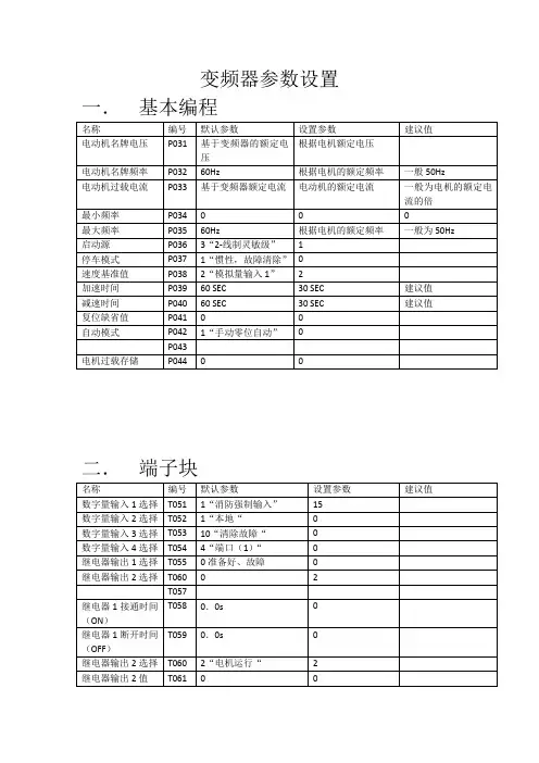


变频器调试步骤第一篇:变频器调试步骤变频器的参数设置和现场调试【变频器的参数设置】变频器的参数设定在调试过程中是十分重要的。
由于参数设定不当,不能满足生产的需要,导致起动、制动的失败,或工作时常跳闸,严重时会烧毁功率模块IGBT或整流桥等器件。
变频器的品种不同,参数量亦不同。
一般单一功能控制的变频器约50~60个参数值,多功能控制的变频器有200个以上的参数。
但不论参数多或少,在调试中是否要把全部的参数重新调正呢?不是的,大多数可不变动,只要按出厂值就可,只要把使用时原出厂值不合适的予以重新设定就可,例如外部端子操作、模拟量操作、基底频率、最高频率、上限频率、下限频率、启动时间、制动时间(及方式)、热电子保护、过流保护、载波频率、失速保护和过压保护等是必须要调正的。
当运转不合适时,再调整其他参数。
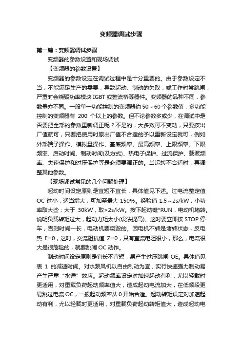
【现场调试常见的几个问题处理】起动时间设定原则是宜短不宜长,具体值见下述。
过电流整定值OC过小,适当增大,可加至最大150%。
经验值1.5~2s/kW,小功率取大些;大于30kW,取>2s/kW。
按下起动键*RUN,电动机堵转。
说明负载转矩过大,起动力矩太小(设法提高)。
这时要立即按STOP停车,否则时间一长,电动机要烧毁的。
因电机不转是堵转状态,反电热E=0,这时,交流阻抗值Z=0,只有直流电阻很小,那么,电流很大是很危险的,就要跳闸OC动作。
制动时间设定原则是宜长不宜短,易产生过压跳闸OE。
具体值见表1的减速时间。
对水泵风机以自由制动为宜,实行快速强力制动易产生严重“水锤”效应。
起动频率设定对加速起动有利,尤以轻载时更适用,对重载负荷起动频率值大,造成起动电流加大,在低频段更易跳过电流OC,一般起动频率从0开始合适。
起动转矩设定对加速起动有利,尤以轻载时更适用,对重载负荷起动转矩值大,造成起动电流加大,在低频段更易跳过电流OC,一般起动转矩从0开始合适。
【基底频率设定】基底频率标准是50Hz时380V,即V/F=380/50=7.6。
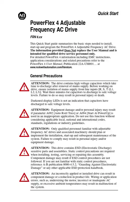
Quick Start PowerFlex 4 AdjustableFrequency AC DriveFRN 6.xxThis Quick Start guide summarizes the basic steps needed to install,start-up and program the PowerFlex 4 Adjustable Frequency AC Drive.The information provided Does Not replace the User Manual and is intended for qualified drive service personnel only.For detailed PowerFlex 4 information including EMC instructions,application considerations and related precautions refer to thePowerFlex4 User Manual, Publication 22A-UM001… at/literature.General Precautions!ATTENTION: The drive contains high voltage capacitors which take time to discharge after removal of mains supply. Before working ondrive, ensure isolation of mains supply from line inputs [R, S, T (L1,L2, L3)]. Wait three minutes for capacitors to discharge to safe voltage levels. Failure to do so may result in personal injury or death.Darkened display LEDs is not an indication that capacitors havedischarged to safe voltage levels.!ATTENTION: Equipment damage and/or personal injury may result if parameter A092 [Auto Rstrt Tries] or A094 [Start At PowerUp] isused in an inappropriate application. Do not use this function withoutconsidering applicable local, national and international codes,standards, regulations or industry guidelines.!ATTENTION: Only qualified personnel familiar with adjustable frequency AC drives and associated machinery should plan orimplement the installation, start-up and subsequent maintenance of the system. Failure to comply may result in personal injury and/orequipment damage.!ATTENTION: This drive contains ESD (Electrostatic Discharge) sensitive parts and assemblies. Static control precautions are requiredwhen installing, testing, servicing or repairing this assembly.Component damage may result if ESD control procedures are notfollowed. If you are not familiar with static control procedures,reference A-B publication 8000-4.5.2, “Guarding Against Electrostatic Damage” or any other applicable ESD protection handbook.!ATTENTION: An incorrectly applied or installed drive can result in component damage or a reduction in product life. Wiring or application errors, such as, undersizing the motor, incorrect or inadequate ACsupply, or excessive ambient temperatures may result in malfunction of the system.English-2•Mount the drive upright on a flat, vertical and level surface.•Protect the cooling fan by avoiding dust or metallic particles.•Do not expose to a corrosive atmosphere.•Protect from moisture and direct sunlight.Ambient Operating TemperaturesRefer to the PowerFlex 4 User Manual for details on how to comply with the Low V oltage (LV) and Electromagnetic Compatibility (EMC) Directives.Mounting ConsiderationsMin. Panel Thickness Screw Size Screw Torque DIN Rail 1.9 mm (0.0747 in.)M4 (#8-32)1.56-1.96 N-m (14-17 lb.-in.)35 mmAmbient Temperature Enclosure RatingMinimum MountingClearancesMinimum Maximum-10°C (14°F)40°C (104°F)IP 20/Open Type Use Mounting Option AIP 30/NEMA 1/UL Type 1(1)(1)Rating requires installation of the PowerFlex 4 IP 30/NEMA 1/UL Type 1 option kit.Use Mounting Option B 50°C (122°F)IP 20/Open Type Use Mounting Option BNo clearance required between drives.General Grounding RequirementsCE ConformityEnglish-3Specifications, Fuses and Circuit BreakersCatalog NumberOutput RatingsInput RatingsBranch Circuit ProtectionPower DissipationkW (HP)Amps Voltage Range kVA Amps Fuses 140M Motor Protectors (2) (3)Contactors Min. Enclosure Volume (4) (in.3)IP20 OpenWatts100 - 120V AC (±10%) – 1-Phase Input, 0 - 230V 3-Phase Output22A-V1P5N1040.2 (0.25)1.590-1260.75 6.010140M-C2E-C10100-C0916553222A-V2P3N1040.4 (0.5) 2.390-126 1.159.015140M-C2E-C16100-C1216554022A-V4P5N1040.75 (1.0)4.590-126 2.2518.030140M-D8E-C20100-C2316555522A-V6P0N1041.1 (1.5)6.090-126 3.024.040140M-F8E-C32100-C37165580200 - 240V AC (±10%) – 1-Phase (1) Input, 0 - 230V 3-Phase Output, NO BRAKE 22A-A1P4N1030.2 (0.25)1.4180-2650.7 3.26140M-C2E-B40100-C0916553222A-A2P1N1030.4 (0.5) 2.1180-2651.05 5.310140M-C2E-B63100-C0916554022A-A3P6N1030.75 (1.0)3.6180-2651.89.215140M-C2E-C16100-C1216555522A-A6P8N103 1.5 (2.0) 6.8180-2653.414.225140M-C2E-C16100-C1616558522A-A9P6N103 2.2 (3.0)9.6180-2654.819.630140M-D8E-C25100-C231655125200 - 240V AC (±10%) – 1-Phase (1)Input, 0 - 230V 3-Phase Output 22A-A1P5N1040.2 (0.25)1.5180-2650.75 5.010140M-C2E-B63100-C0916553222A-A2P3N1040.4 (0.5) 2.3180-2651.15 6.010140M-C2E-B63100-C0916554022A-A4P5N1040.75 (1.0)4.5180-2652.2510.015140M-C2E-C16100-C1216555522A-A8P0N104 1.5 (2.0)8.0180-2654.018.030140M-D8E-C20100-C23165585200 - 240V AC (±10%) – 3-Phase Input, 0 - 230V 3-Phase Output22A-B1P5N1040.2 (0.25)1.5180-2650.75 1.83140M-C2E-B25100-C0916553222A-B2P3N1040.4 (0.5)2.3180-2651.15 2.56140M-C2E-B40100-C0916554022A-B4P5N1040.75 (1.0)4.5180-2652.25 5.210140M-C2E-C10100-C0916555522A-B8P0N104 1.5 (2.0)8.0180-2654.09.515140M-C2E-C16100-C1216558522A-B012N104 2.2 (3.0)12.0180-2655.515.525140M-C2E-C16100-C16165512522A-B017N1043.7 (5.0)17.5180-2658.621.030140M-F8E-C25100-C231655180Recommended Fuses and Circuit BreakersFuse: UL Class J, CC, T or Type BS88; 600V (550V) or equivalent. Circuit Breakers: HMCP or Bulletin 140U or equivalent.Protective FeaturesMotor Protection: I 2t overload protection - 150% for 60 Secs, 200% for 3 Secs (Provides Class 10 protection)Overcurrent: 200% hardware limit, 300% instantaneous fault Over Voltage:100-120V AC Input – Trip occurs at 405V DC bus voltage (equivalent to 150V AC incoming line)200-240V AC Input – Trip occurs at 405V DC bus voltage (equivalent to 290V AC incoming line)380-460V AC Input – Trip occurs at 810V DC bus voltage (equivalent to 575V AC incoming line)Under Voltage:100-120V AC Input – Trip occurs at 210V DC bus voltage (equivalent to 75V AC incoming line)200-240V AC Input – Trip occurs at 210V DC bus voltage (equivalent to 150V AC incoming line)380-480V AC Input – Trip occurs at 390V DC bus voltage (equivalent to 275V AC incoming line)Control Ride Through: Minimum ride through is 0.5 Secs - typical value 2 Secs Faultless Power Ride Through: 100 millisecondsDynamic BrakingInternal brake IGBT included with all ratings except No Brake versions. Refer to Appendix B of the PowerFlex 4 User Manual for DB resistor ordering information.(1)200-240V AC - 1-Phase drives are also available with an integral EMC filter. Catalog suffix changes from N103 to N113 and N104 to N114.English-4Power Terminal Block SpecificationsInput Power ConditionsI/O Terminal Block Specifications(2)The AIC ratings of the Bulletin 140M Motor Protector Circuit Breakers may vary. See Bulletin 140M Motor Protection Circuit Breakers Application Ratings .(3)Manual Self-Protected (Type E) Combination Motor Controller, UL listed for 208 Wye or Delta, 240 Wye or Delta, 480Y/277 or 600Y/347. Not UL listed for use on 480V or 600V Delta/Delta, corner ground, or high-resistance ground systems.(4)When using a Manual Self-Protected (Type E) Combination Motor Controller, the drive must be installed in a ventilated or non-ventilated enclosure with the minimum volume specified in this column. Application specific thermal considerations may require a larger enclosure.Power WiringPower Wire RatingRecommended Copper WireUnshielded 600V, 75°C (167°F) THHN/THWN15 Mils insulated, dry location Shielded 600V, 75°C or 90°C (167°F or 194°F) RHH/RHW-2Belden 29501-29507 or equivalent Shielded Tray rated 600V, 75°C or 90°C (167°F or 194°F) RHH/RHW-2Shawflex 2ACD/3ACD or equivalentFrameMaximum Wire Size (1)Minimum Wire Size (1)TorqueA 3.3 mm 2 (12 AWG)0.8 mm 2 (18 AWG) 1.7-2.2 N-m (16-19 lb.-in.)B 5.3 mm 2 (10 AWG)1.3 mm 2 (16 AWG)(1)Maximum/minimum sizes that the terminal block will accept - these are not recommendations.Input Power ConditionCorrective ActionLow Line Impedance (less than 1% line reactance)•Install Line Reactor (2)•or Isolation TransformerGreater than 120 kVA supply transformer Line has power factor correction capacitors Line has frequent power interruptionsLine has intermittent noise spikes in excess of 6000V (lightning)Phase to ground voltage exceeds 125% of normal line to line voltage •Remove MOV jumper to ground.•or Install Isolation Transformer with grounded secondary if necessary.Ungrounded Distribution System (2)Refer to Appendix B of the PowerFlex 4 User Manual for accessory ordering information.I/O Wiring Recommendations (3)Wire Type(s)Description Minimum Insulation RatingBelden 8760/9460(or equiv.)0.8 mm 2(18AWG), twisted pair, 100% shield withdrain.300V 60 degrees C (140 degrees F)Belden 8770(or equiv.)0.8 mm 2(18AWG), 3 conductor, shielded for remote pot only.(3)If the wires are short and contained within a cabinet which has no sensitive circuits, the use of shielded wire may not benecessary, but is always recommended.Maximum Wire Size (4)Minimum Wire Size (4)Torque1.3 mm 2 (16 AWG)0.13 mm 2 (26 AWG)0.5-0.8 N-m (4.4-7 lb.-in.)(4)Maximum / minimum that the terminal block will accept - these are not recommendations.English-5 Refer to the PowerFlex 4 User Manual for recommendations onmaximum power and control cable length.Control Terminal BlockSink/Source DIP Switch Source (SRC)Inputs can be wired as Sink (SNK) or Source (SRC) via DIP Switch setting.01Stop(1)Coast The factory installed jumper or a normally closed inputmust be present for the drive to start.P036(1)02Start/Run FWD Not ActiveCommand comes from the integral keypad by default. Todisable reverse operation, see A095 [Reverse Disable].P036, P03703Direction/Run REV Not Active P036, P037, A09504Digital Common–For digital inputs. Electronically isolated with digital inputs from analog I/O.05Digital Input 1Preset Freq Program with A051 [Digital In1 Sel].A051 06Digital Input 2Preset Freq Program with A052 [Digital In2 Sel].A05211+24V DC–Drive supplied power for digital inputs. Maximum output current is 100mA.12+10V DC–Drive supplied power for 0-10V external potentiometer. Maximum output current is 15mA.P038130-10V In(3)Not Active For external 0-10V input supply(input impedance = 100k ohm) or potentiometer wiper.P03814Analog Common–For 0-10V In or 4-20mA In. Electronically isolated with analog inputs from digital I/O.(1) Important: I/O Terminal 01 is always a coast to stop input except when P036 [Start Source] is set to “3-Wire” control. In three wire control, I/O Terminal 01 is controlled by P037 [Stop Mode]. All other stopRefer to the PowerFlex 4User Manual for moreinformation.P036[Start Source]StopI/O Terminal 01StopKeypad Per P037Coast3-Wire Per P037Per P0372-Wire Per P037CoastRS485 Port Per P037CoastEnglish-6Before Applying Power to the Drive❏ 1.Confirm that all inputs are connected to the correct terminals and are secure.❏2.Verify that AC line power at the disconnect device is within the rated value of the drive.❏ 3.Verify that any digital control power is 24 volts.❏ 4.Verify that the Sink (SNK)/Source (SRC) Setup DIP Switch is set tomatch your control wiring scheme. See page 5 for location.Important:The default control scheme is Source (SRC). The Stopterminal is jumpered (I/O Terminals 01 and 11) to allow starting from the keypad. If the control scheme is changed to Sink (SNK), the jumper must be removed from I/O Terminals 01 and 11 and installed between I/O Terminals 01 and 04.❏5.Verify that the Stop input is present or the drive will not start.Important:If I/O Terminal 01 is used as a stop input, the jumperbetween I/O Terminals 01 and 11 must be removed.Applying Power to the Drive❏ 6.Apply AC power and control voltages to the drive.❏7.Familiarize yourself with the integral keypad features (see next page)before setting any Program Group parameters.Start, Stop, Direction and Speed ControlFactory default parameter values allow the drive to be controlled from the integral keypad. No programming is required to start, stop, change direction and control speed directly from the integral keypad.Important:To disable reverse operation, see A095 [Reverse Disable].If a fault appears on power up, refer to page 11 for an explanation of the fault code. For complete troubleshooting information, refer to the PowerFlex 4 User Manual .154-20mA In (3)Not Active For external 4-20mA input supply(input impedance = 250 ohm).P03816RS485 (DSI) Shield–Terminal should be connected to safety ground - PE when using the RS485 (DSI) communications port.(3)Only one analog frequency source may be connected at a time. If more than one reference is connected at the same time, an undetermined frequency reference will result.No.SignalDefaultDescription Param.Prepare For Drive Start-Up!ATTENTION: Power must be applied to the drive to perform the following start-up procedures. Some of the voltages present are at incoming line potential. To avoid electric shock hazard or damage to equipment, only qualified service personnel should perform the following procedure. Thoroughly read and understand the procedure before beginning. If an event does not occur while performing this procedure, Do Not Proceed . Remove All Power including usersupplied control voltages. User supplied voltages may exist even when main AC power is not applied to the drive. Correct the malfunction before continuing.English-7 Integral KeypadNo.LED LED State Description➊Run/DirectionStatus Steady Red Indicates drive is running and commanded motor direction. Flashing Red Drive has been commanded to change direction. Indicatesactual motor direction while decelerating to zero.➋AlphanumericDisplay Steady Red Indicates parameter number, parameter value, or fault code. Flashing Red Single digit flashing indicates that digit can be edited.All digits flashing indicates a fault condition.➌Displayed Units Steady Red Indicates the units of the parameter value being displayed.➍Program Status Steady Red Indicates parameter value can be changed.➎Fault Status Flashing Red Indicates drive is faulted.➏Pot Status Steady Green Indicates potentiometer on Integral Keypad is active.➐Start Key Status Steady Green Indicates Start key on Integral Keypad is active.The Reverse key is also active unless disabled by A095[Reverse Disable].English-8The last user-selected Display Group parameter is saved when power is removed and is displayed by default when power is reapplied.The following is an example of basic integral keypad and display functions. This example provides basic navigation instructions and illustrates how to program the first ProgramViewing and Editing ParametersSee the PowerFlex 4 User Manual for more information on parameters.English-9 See the PowerFlex 4 User Manual for more information on parameters.Display Group ParametersNo.Parameter Min/Max Display/Optionsd001[Output Freq]0.0/[Maximum Freq]0.1 Hzd002[Commanded Freq]0.0/[Maximum Freq]0.1 Hzd003[Output Current]0.00/(Drive Amps × 2)0.01 Ampsd004[Output Voltage]0/Drive Rated Volts 1 VACd005[DC Bus Voltage]Based on Drive Rating 1 VDCd006[Drive Status]0/1 (1 = Condition True)Bit 3Bit 2Bit 1Bit 0Decelerating Accelerating Forward Running [Fault x Code]F2/F122F1d007-d009d010[Process Display]0.00/99990.01 – 1d012[Control Source]0/9Digit 1 = Speed Command Digit 0 = Start Command(See P038; 9 = “Jog Freq”)(See P036; 9 = “Jog”)d013[Contrl In Status]0/1 (1 = Input Present)Bit 3Bit 2Bit 1Bit 0Reserved Stop Input Dir/Run REV Start/Run FWD d014[Dig In Status]0/1 (1 = Input Present)Bit 3Bit 2Bit 1Bit 0Reserved Reserved Digital In2 Sel Digital In1 Sel d015[Comm Status]0/1 (1 = Condition True)Bit 3Bit 2Bit 1Bit 0Fault Occurred RS485 Option Transmitting Receivingd016[Control SW Ver] 1.00/99.990.01d017[Drive Type]1001/99991d018[Elapsed Run Time]0/9999 Hrs 1 = 10 Hrsd019[Testpoint Data]0/FFFF 1 Hexd020[Analog In 0-10V]0.0/100.0%0.1%d021[Analog In 4-20mA]0.0/100.0%0.1%d024[Drive Temp]0/120 degC 1 degCSmart Start-Up with Basic Program Group ParametersEnglish-10See the PowerFlex 4 User Manual for more information on parameters.Advanced Group ParametersEnglish-11To clear a fault, press the Stop key, cycle power or set A100 [Fault Clear] to 1 or 2.A103[Comm Data Rate](3)0/50 = “1200”1 = “2400”2 = “4800”3 = “9600”4 = “19.2K”5 = “38.4K”3A104[Comm Node Addr](3)1/2471100A105[Comm Loss Action]0/30 = “Fault”1 = “Coast to Stop”2 = “Stop”3 = “Continu Last”0A106[Comm Loss Time]0.1/60.00.15.0A107[Comm Format](3)0/50 = “RTU 8-N-1”1 = “RTU 8-E-1”2 = “RTU 8-O-1”3 = “RTU 8-N-2”4 = “RTU 8-E-2”5 = “RTU 8-O-2”0A110[Anlg In 0-10V Lo]0.0/100.0%0.1%0.0%A111[Anlg In 0-10V Hi]0.0/100.0%0.1%100.0%A112[Anlg In4-20mA Lo]0.0/100.0%0.1%0.0%A113[Anlg In4-20mA Hi]0.0/100.0%0.1%100.0%A114[Slip Hertz @ FLA]0.0/10.0 Hz 0.1 Hz 2.0 Hz A115[Process Time Lo]0.00/99.990.010.00A116[Process Time Hi]0.00/99.990.010.00A117[Bus Reg Mode]0/10 = “Disabled” 1 = “Enabled”1A118[Comm Write Mode]0/10 = “Save”1 = “RAM Only”(3) Power to drive must be cycled before any changes will affect drive operation.No.ParameterMin/MaxDisplay/OptionsDefaultFault CodesNo.FaultDescriptionF2Auxiliary Input (1)Check remote wiring.F3Power Loss Monitor the incoming AC line for low voltage or line power interruption.F4UnderVoltage (1)Monitor the incoming AC line for low voltage or line power interruption.F5OverVoltage (1)Monitor the AC line for high line voltage or transient conditions. Bus overvoltage can also be caused by motor regeneration. Extend the decel time or install dynamic brake option.F6Motor Stalled (1)Increase [Accel Time x] or reduce load so drive output current does not exceed the current set by parameter A089 [Current Limit].F7Motor Overload (1)An excessive motor load exists. Reduce load so drive output current does not exceed the current set by parameter P033 [Motor OL Current].F8Heatsink OvrTmp (1)Check for blocked or dirty heat sink fins. Verify that ambient temperature has not exceeded 40°C (104°F) for IP 30/NEMA 1/UL T ype 1 installations or 50°C (122°F) for Open type installations.Check fan.F12HW OverCurrent (1)Check programming. Check for excess load, improper DC boost setting, DC brake volts set too high or other causes of excess current.F13Ground Fault Check the motor and external wiring to the drive output terminals for a grounded condition.F33Auto Rstrt Tries Correct the cause of the fault and manually clear.F38Phase U to Gnd Check the wiring between the drive and motor. Check motor for grounded phase.Replace drive if fault cannot be cleared.F39Phase V to Gnd F40Phase W to Gnd F41Phase UV Short Check the motor and drive output terminal wiring for a shorted condition.Replace drive if fault cannot be cleared.F42Phase UW Short F43Phase VW Short F48Params DefaultedThe drive was commanded to write default values to EEPROM. Clear the fault or cycle power to the drive. Program the drive parameters as needed.F63SW OverCurrent (1)Check load requirements and A098 [SW Current Trip] setting.F64Drive Overload Reduce load or extend Accel Time.F70Power Unit Cycle power. Replace drive if fault cannot be cleared.F71Net Loss The communication network has faulted.F81Comm Loss If adapter was not intentionally disconnected, check wiring to the port. Replace wiring, portexpander, adapters or complete drive as required. Check connection. An adapter was intentionally disconnected. Turn off using A105 [Comm Loss Action].F100Parameter Checksum Restore factory defaults.F122I/O Board Fail Cycle power. Replace drive if fault cannot be cleared.(1)Auto-Reset/Run type fault. Configure with parameters A092 and A093.See the PowerFlex 4 User Manual for more information on parameters.English-12PowerFlex 4 Panel Mount Drives – Ratings are in kW and (HP)PowerFlex 4 Panel Mount Drives (1)– Dimensions are in millimeters and (inches).(1)Flange Mount drives are also available. Refer to the PowerFlex 4 User Manual for more information.(2)Overall height of drive with IP 30/NEMA 1/UL Type 1 option kit installed.(3)Overall height of standard IP 20/Open Type drive.IP 30/NEMA 1/UL Type 1 Option Kit – Dimensions are in millimeters and (inches)Publication 22A-QS001I-EN-P – June 2013Supersedes Publication 22A-QS001H-EN-P – October 2009Copyright © 2013 Rockwell Automation, Inc. All rights reserved.Drive DimensionsF r a m e120V AC – 1-Phase240V AC – 1-PhaseNo Brake240V AC – 1-Phase 240V AC – 3-Phase 480V AC – 3-PhaseA0.2 (0.25)0.37(0.5)0.2 (0.25)0.37 (0.5)0.75 (1.0)0.2 (0.25)0.37 (0.5)0.75 (1.0)0.2 (0.25)0.37 (0.5)0.75 (1.0)1.5 (2.0)0.37 (0.5)0.75 (1.0)1.5 (2.0)B0.75(1.0)1.1 (1.5)1.5 (2.0)2.2 (3.0)1.5 (2.0)2.2 (3.0)3.7 (5.0)2.2 (3.0)3.7 (5.0)Frameab (2)cde (3)fgShipping WeightA 80 (3.15)185 (7.28)136 (5.35)67 (2.64)152 (5.98)59.3 (2.33)140 (5.51) 1.4 (3.1)B100 (3.94)213 (8.39)136 (5.35)87 (3.43)180 (7.09)87.4 (3.44)168 (6.61)2.2 (4.9)U.S. Allen-Bradley Drives Technical SupportTel:(1)262.512.8176,Fax:(1)262.512.2222,Email:*****************,Online:/support/abdrives。
PowerFlex 40 Adjustable Frequency AC Drive PowerFlex 40变频器User Manual用户手册重要用户信息固态设备具有不同于电动机械设备的操作特性。
《固态控制器的应用、安装和维护安全指南》(出版号SG I-1.1,本资料可从当地的Rockwell销售办事处或/manuals/gi获得)说明了固态设备和硬接线电动机械设备之间的重要差别。
由于这些差别的存在以及固态设备应用的多样性,因此所有技术人员有责任确保这些固态设备的每项应用是可行的。
罗克韦尔自动化公司绝不承担因使用该设备而引起的间接或灾后损失的责任或义务。
本手册所包含的例子和图表仅仅用于说明。
因为任何特定安装有着特定的变化因素和需求,所以罗克韦尔自动化公司不承担用户基于例子和图表中实际应用的任何责任或义务。
关于本手册中所说明的信息、电路、设备或软件,罗克韦尔自动化公司不承担任何专利责任。
如果没有得到罗克韦尔自动化公司书面允许,严厉禁止任何团体、公司、个人对本手册的内容进行整体或部分复制。
我们使用了注释贯穿于本手册,提醒用户作安全考虑。
本手册系根据英文原文版翻译而成。
本手册中若有与英文不符之处,请以英文为准。
252627注意事项:是指有关导致人员伤亡、财产损害或经济损失的实际应用或环境情况。
注意事项可以帮助用户z识别危害z避免危害z认识危害所带来后果重要事项:是指用户对有关产品正确理解和应用所需掌握的重要信息。
DriveExploer,Drive tools32和SCANport是罗克韦尔自动化公司的商标。
PLC是罗克韦尔自动化公司的登记注册商标。
ControlNet是ControlNet国际有限公司的商标。
DeviceNet是Open DeviceNet Vendor Association的商标。
目录前言概述谁应该使用本用户手册… ……………. .P-1参考资料…………………………………………P-1手册定义 ……………………………………P-2变频器外形尺寸…………………………………P-2预防措施… …………………………………P-3产品目录号说明…………………………………P-4 第一章安装/接线打开面板………………………………………….1-1安装注意事项……………………………………1-2交流电源注意事项 ………………… 1-3接地要求…… ………………………………1-4熔断器和断路器…………………………………1-6电源接线…………………………………………1-8I/O接线 ……………………………………..1-12起动和速度给定控制………………………… 1-20EMC电磁兼容指南……………………………..1-22 第二章起动变频器启动前的准备工作 ……………………2-1操作面板 ……………………………………2-3参数浏览和编辑…………………………………2-4远程操作面板2-5 第三章编程与参数关于参数 ………………………………… 3-1参数构成…………………………………………3-2显示组……………………………………………3-3基本程序(设置)组 …………………… . 3-9高级程序(设置)组 …………………………… 3-14参数对照-按名称(英文字母)顺序…………… 3-42 第四章故障处理变频器状态………………………………………4-1故障情况……………………………………… 4-1故障说明…………………………………………4-3常见故障和处理措施……………………………4-5 附录A 变频器附加信息变频器、熔断器和断路器的额定值…………….A-1技术规范 ……………………………………… A-2 附录B 附件和尺寸产品选型………………………………………….B-1产品尺寸………………………………………… B-7 附录C RS485(DSI)协议附录D RJ45 DSI 分裂式电缆附录E 基本逻辑、步序逻辑和定时器/计数器功能附录F PID 设置索引前言概述本手册的目的是为用户提供PowerFlex40交流变频器的安装、起动和故障处理所需的基本信息。

变频器调试的基本方法和步骤变频器是利用电力半导体器件的通断作用将工频电源变换为另一频率的电能控制装置,能实现对交流异步电机的软起动、变频调速、提高运转精度、改变功率因数、过流/过压/过载保护等功能。
主要应用在风机、水泵的应用上。
为了保证生产的可靠性,各种生产机械在设计配用动力驱动时,都留有一定的富余量。
当电机不能在满负荷下运行时,除达到动力驱动要求外,多余的力矩增加了有功功率的消耗,造成电能的浪费。
风机、泵类等设备传统的调速方法是通过调节入口或出口的挡板、阀门开度来调节给风量和给水量,其输入功率大,且大量的能源消耗在挡板、阀门的截流过程中。
当使用变频调速时,如果流量要求减小,通过降低泵或风机的转速即可满足要求。
以下谈下一般变频器调试的基本方法。
变频器调试的基本方法和步骤:一、变频器的空载通电验1、将变频器的接地端子接地。
2、将变频器的电源输入端子经过漏电保护开关接到电源上。
3、检查变频器显示窗出厂显示是否正常,如果不正确,应复位,否则要求退换。
4、熟悉变频器的操作键。
一般的变频器均有运行(RUN)、停止(STOP)、编程(PROG)、数据P确认(DATAPENTER)、增加(UP、▲)、减少(DOWN、)等6个键,不同变频器操作键的定义基本相同。
此外有的变频器还有监视(MONITORPDISPLAY)、复位(RESET)、寸动(JOG)、移位(SHIFT)等功能键。
二、变频器带电机空载运行1、设置电机的功率、极数,要综合考虑变频器的工作电流。
2、设定变频器的最大输出频率、基频、设置转矩特性。
通用变频器均备有多条VPf曲线供用户选择,用户在使用时应根据负载的性质选择合适的VPf曲线。
如果是风机和泵类负载,要将变频器的转矩运行代码设置成变转矩和降转矩运行特性。
为了改善变频器启动时的低速性能,使电机输出的转矩能满足生产负载启动的要求,要调整启动转矩。
在异步电机变频调速系统中,转矩的控制较复杂。
在低频段,由于电阻、漏电抗的影响不容忽略,若仍保持VPf为常数,则磁通将减小,进而减小了电机的输出转矩。
变频器调试的基本步骤-变频器的通用调试方法一、变频器的空载通电验1.将变频器的接地端子接地。
2.将变频器的电源输入端子经过漏电保护开关接到电源上。
3.检查变频器显示窗的出厂显示是否正常如果不正确应复位否则要求退换。
4.熟悉变频器的操作键。
一般的变频器均有运行(RUN) 、停止(STOP) 、编程(PROG) 、数据 P 确认 (DATAPENTER) 、增加(UP、▲) 、减少(DOWN、') 等 6 个键不同变频器操作键的定义基本相同。
此外有的变频器还有监视(MONITORPDISPLAY) 、复位(RESET) 、寸动(JOG) 、移位(SHIFT) 等功能键。
二、变频器带电机空载运行1.设置电机的功率、极数要综合考虑变频器的工作电流。
2.设定变频器的最大输出频率、基频、设置转矩特性。
VPf 类型的选择包括最高频率、基本频率和转矩类型等项目。
最高频率是变频器—电动机系统可以运行的最高频率由于变频器自身的最高频率可能较高当电动机容许的最高频率低于变频器的最高频率时应按电动机及其负载的要求进行设定。
基本频率是变频器对电动机进行恒功率控制和恒转矩控制的分界线应按电动机的额定电压进行设定。
转矩类型指的是负载是恒转矩负载还是变转矩负载。
用户根据变频器使用说明书中的VPf 类型图和负载特点选择其中的一种类型。
通用变频器均备有多条VPf 曲线供用户选择用户在使用时应根据负载的性质选择合适的VPf 曲线。
如果是风机和泵类负载要将变频器的转矩运行代码设置成变转矩和降转矩运行特性。
为了改善变频器启动时的低速性能使电机输出的转矩能满足生产负载启动的要求要调整启动转矩。
在异步电机变频调速系统中转矩的控制较复杂。
在低频段由于电阻、漏电抗的影响不容忽略若仍保持VPf 为常数则磁通将减小进而减小了电机的输出转矩。
为此在低频段要对电压进行适当补偿以提升转矩。
一般变频器均由用户进行人工设定补偿。
日立 J300 变频器则为用户提供两种选择:自行设定和自动转矩提升。
变频器接线与解密调试步骤
变频器一般情况下,都是不需要我们服务人员或者电工去配线的,因为设备在工厂一般都会安装调试后再发货,如果碰上更换变频器或者电路板的情况,今天聊一聊,我们怎么去接线和调试参数呢?
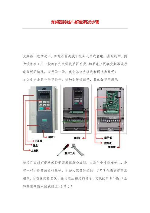
首先肯定是要先拆下外壳,接触到接线端子,具体如下图所示
如果你面前有麦格米特变频器你就会看到,在每个小接线端子上,是有一些小标签或者叫线号,比如大家都知道的,U V W代表的就是三相电。
而在变频器里属于输出电压接线的端子,其他的参考下图。
(正转的信号输入线就接X1号端子)
配线结束之后,再仔细检查一遍,如果确定配线无误,然后就可以给变频器通电调试了,前一篇文章我们说到过,麦格米特变频器如果想要查看或者修改参数,就需要先解密
因为某些设备厂家是定制变频器的是动态密码,所以P00.00显示的
是随机数,等P00.001=随机数生效,然后我们就可以调节参数了。

PowerFlex 低壓變頻器性能強大。
靈活操控。
2Rockwell Automation 出版品 PFLEX-SG002P-ZC-P - 2022 年10 月PowerFlex 低壓變頻器產品選型指南內容最新消息擴大 TotalFORCE 技術的使用修訂版 11 韌體版本•支援氣冷式 PowerFlex® 755TS 變頻器-框架 1 7,400V/480V-預測維護有助於避免意外停機時間-支援 TotalFORCE® 電力供應選項卡,在三相電源斷電時保持控制和通訊作用-扭矩準確度模組 (框架 2...7) - 改善捲繞機、拆捲機與測試台等敏感應用的扭矩準確度-動態煞車功能 - 釋放過量的直流匯流排能量⽽不需將其送回主電源-額外的停止模式 - 用於在不將過多的再⽣能量送回直流匯流排時進⾏減速•支援250Hp 額定值的氣冷式框架6PowerFlex 755TL、755TM 與755TR •安全擦除有助於保護客戶的知識產權•用於進⾏ PowerFlex 755TL、755TM 與 755TR 變頻器故障檢測的電源轉入式故障與警示資訊參數PowerFlex 755TS 交流變頻器PowerFlex 755TS 變頻器是結合 TotalFORCE 技術的傳統六脈衝變頻器。
在此之前,TotalFORCE 僅能在採用主動式前端技術的 PowerFlex 755T 變頻器中使用,⽽現在應用範圍更加廣泛。
其中包括⾵扇、幫浦與輸送帶應用,以及更進階的馬達控制製程,⽽這些製程需要專用變頻器解決方案中常⾒的⾼效能功能。
PowerFlex 755TS 採用三種主要方式,為幾乎所有的馬達控制應用提供簡化且一致的使用者體驗:•彈性、⾼效能的控制•即時營運智慧與預測維護•在 Studio 5000® 設計環境中可輕鬆進⾏設定、整合和視覺化PowerFlex 755TM 變頻器的非再生電源在不需要再⽣與低諧波時,提供適合共用匯流排之節省空間、具成本效益的解決方案。
审核:编制:序号项 目图 片更换方法及标准控制要点检查者2准备工作2更换备件确认确认损坏的变频器与备件型号是否一致1、提前准备好变频器备件,确认完好。
2、确认备件型号是否一致(例如:0.75KW/1.0HP是否完全一样,如不一样,见更换标准2)。
3、悬挂安全警示牌。
1、确认备件完好与型号时必须仔细,否则会造成返工,影响工作效率。
2、现场张贴安全警示标志付鑫参数设置要准确无误变频器更换无误后,就可以上电运行,如上电可以断电在从新上电,即可完成更换付鑫付鑫付鑫付鑫付鑫付鑫付鑫确认工具齐全数据备份要准确变频器带有高电压的电容器,在供电结束后它需要一定时间进行放电,在变频器工作前,确保电源盒输入线路的绝缘。
等待3min,以使电容器放电达到安全电压等级。
否则,可能导致人员伤害或死亡。
拆线前务必验电,即使知道已断电,养成良好的作业习惯。
拆线时,螺丝不要松的太大,松动即可,防止螺丝丢失线号与接线端子一一对应,以免接线时引起不必要的麻烦。
轻拿轻放,避免损坏接线时,与拆除时记录一一对应接线,接线完成后,确认是否正确。
确认工具齐全1、按控制面板ESC键,显示上电后的显示组参数 参数号闪烁再次按下ESC键 进入参数组菜单 按下向上或者向下箭头在组菜单中滚动(d,P,A) 选择P 按下SEL键进入参数组 记下参数代码 按下SEL键 显示当前参数值 并记录 P031(电动机铭牌电压)=380V,P032(电动机铭牌频率)=50 HZ,P032(电动机过载电流)=10.2A,P034(最小频率)电笔验电1、首先拆掉主回路输入主电源,R(L1) S(L2) T(L3) 并记录与之对应的接线端子线号,拆下输出电源U(T1) V(T2)W(T3) 并记录与之对应的接线端子线号。
2、然后拆除控制回路,拆下变频器控制回路接线端子上面的控制线,并记录与之对应的线号3、最后拆除安全接地线和5针线数据连接器在电柜背板上面拆除损坏的变频器,更按照原有方式换新的变频器。
变频器怎样调试首要应作为到以下几个进程:一、变频器的空载通电查验1 将变频器的接地端子接地。
2 将变频器的电源输入端子经过漏电维护开关接到电源上。
3 检查变频器闪现窗出厂闪现是不是正常,假定禁绝确,应复位,不然央求退换。
4 了解变频器的操作键。
通常的变频器均有作业(RUN) 、接连(STOP) 、编程(PROG) 、数据P招认(DATAPENTER) 、添加(UP、▲) 、削减(DOWN、") 等6个键,纷歧样变频器操作键的界说根柢相同。
此外有的变频器还有监督(MONITORPDISPLAY) 、复位(RESET) 、寸动(JOG) 、移位(SHIFT) 等功用键。
二、变频器带电机空载作业1.设置电机的功率、极数,要归纳思考变频器的作业电流。
2.设定变频器的最大输出频率、基频、设置转矩特性。
通用变频器均备有多条VPf 曲线供用户挑选,用户在运用时应依据负载的性质挑选适宜的VPf 曲线。
假定是风机和泵类负载,要将变频器的转矩作业代码设置成变转矩和降转矩作业特性。
为了改进变频器主张时的低速功用,使电机输出的转矩能满意出产负载主张的央求,要调整主张转矩。
在异步电机变频调速体系中,转矩的操控较杂乱。
在低频段,由于电阻、漏电抗的影响不容疏忽,若仍坚持VPf 为常数,则磁通将减小,进而减小了电机的输出转矩。
为此,在低频段要对电压进行恰当抵偿以跋涉转矩。
通常变频器均由用户进行人工设定抵偿。
3.将变频器设置为自带的键盘操作办法,按作业键、接连键,查询电机是不是能正常地主张、接连。
. 4. 了解变频器作业发作缺陷时的维护代码,查询热维护继电器的出厂值,查询过载维护的设定值,需求时能够批改。
变频器的运用人员能够按变频器的运用阐明书对变频器的电子热继电器功用进行设定。
当变频器的输出电流跨过其容许电流时,变频器的过电流维护将堵截变频器的输出。
因而,变频器电子热继电器的门限最大值不跨过变频器的最大容许输出电流。
功率因数CosΦ=P/( √3 UI) = 11KW / (√3 ×380V×21.3A) = 0.781不需设置0.8911KW 21.3A 380V50HZ 2930rpm2然后还要进行下列参数设置:见图11、控制端子排上的DIP1拨到ON状态,见图2,图32、P0701[0]=2,表示接通反转/停止命令1;见图83、P0732改为52.2,以选择数字量输出2作为变频器运行与否的反馈信号,见图54、P0756[0]=2,表示模拟量1为0-20mA输入;见图4,图55、P0771[0]=24,表示变频器实际输出频率,见图66、P0773=1000,表示变频器实际输出频率的滤波时间为1000ms,见图67、P0775[0]=1,表示模拟量1输出取绝对值;见图118、P700[0]=2,端子排输入9、P1000[0]=2 , 模拟输入值另外,如果用操作面板BOP操作变频器启停和设置频率需要1、P700[0]=1, BOP设置启停2、P701[0]=0 , 禁止数字量输入(即5端子不起作用)3.P1000[0] =1 MOP设定值为频率设定值同时需要变频器重新上电后,操作面板BOP操作变频器启停和设置频率功能可用图1频率设定图4复位图10启动图7频率输出图6故障输出图5运行图5 P0756[0]=2P0771[0]=24P0732=52.2黄色字体参数为默认值,无须修改。
图2图3图4图5图6图7图8图9图8中P0701=1,的含义是:当数字输入1(5端子)和公共端(9端子)连通时,电机正转;当数字输入1(5端子)和公共端(9端子)断开时,电机停止。
图9中P0702=12,的含义是:当数字输入1(5端子)和公共端(9端子)连通时,同时当数字输入2(6端子)和公共端(9端子)也连通时,电机跟仅当数字输入1(5端子)和公共端(9端子)连通时电机的转向方向相反。
图10图11。