ieee1241标准
- 格式:doc
- 大小:11.01 KB
- 文档页数:2
ieee试验标准
IEEE(电气电子工程师协会)是一个国际性的学术和技术组织,致力于推动电气、电子和计算机工程领域的研究、开发和标准化。
IEEE 制定了许多试验标准,这些标准为各种电子设备和系统的测试和评估提供了指导。
以下是一些IEEE试验标准的例子:
1.IEEE 80
2.3:以太网标准,用于局域网(LAN)中的有线连接。
2.IEEE 802.11:无线局域网(WLAN)标准,用于无线连接。
3.IEEE 802.15:无线个人局域网(WPAN)标准,用于近距离无线通信,
如蓝牙和ZigBee。
4.IEEE 802.16:宽带无线接入(BWA)标准,用于无线宽带通信。
5.IEEE 802.20:移动宽带无线接入(MBWA)标准,用于移动设备无
线通信。
6.IEEE 1588:网络测量和控制系统的精确时间协议(PTP),用于精确
同步网络中的设备时钟。
7.IEEE 2030:能源互联网标准,用于智能电网和可再生能源系统的互
操作性和安全性。
这只是IEEE试验标准的一小部分,IEEE还制定了涵盖许多其他领域的标准和规范,包括电信、电力、交通、医疗等。
这些标准对于
确保设备和系统的互操作性和可靠性至关重要,并为工程师和技术人员提供了指导和支持。
ieee 水轮机标准
IEEE水轮机标准是指由国际电气和电子工程师协会(IEEE)制定的关于水轮机的技术标准。
水轮机是一种将水能转化
为机械能的装置,常用于发电和水利工程中。
目前,IEEE并没有单独制定水轮机的标准,但是有一些与
水轮机相关的标准和指南可以参考,如下所示:
1. IEEE 115-2009: "IEEE Guide for Test Procedures
for Synchronous Machines Part I - Acceptance and Performance Testing"
这个标准主要涉及同步机的测试程序,虽然不是专门针对
水轮机,但是水轮机也属于同步机的一种。
2. IEEE 1248-2010: "IEEE Guide for the Commissioning of Electrical Systems in
Hydroelectric Power Plants"
这个标准主要涉及水力发电厂电气系统的验收和调试,其
中包括水轮机的相关内容。
此外,还有一些其他的国际标准和行业指南可以参考,如
国际电工委员会(IEC)的标准和美国机械工程师协会(ASME)的指南等。
需要注意的是,水轮机的设计、制造和安装通常需要遵循
国家和地区的相关法规和标准,因此在具体项目中应根据当地的要求和规定进行设计和实施。

IEEE Std1241-2000 IEEE Standard for Terminology and Test Methods for Analog-to-Digital ConvertersSponsorWaveform Measurement and Analysis Technical Committeeof theof theIEEE Instrumentation and Measurement SocietyApproved7December2000IEEE-SA Standards BoardAbstract:IEEE Std1241-2000identifies analog-to-digital converter(ADC)error sources and provides test methods with which to perform the required error measurements.The information in this standard is useful both to manufacturers and to users of ADCs in that it provides a basis for evaluating and comparing existing devices,as well as providing a template for writing specifications for the procurement of new ones.In some applications,the information provided by the tests described in this standard can be used to correct ADC errors, e.g.,correction for gain and offset errors.This standard also presents terminology and definitions to aid the user in defining and testing ADCs.Keywords:ADC,A/D converter,analog-to-digital converter,digitizer,terminology,test methodsThe Institute of Electrical and Electronics Engineers,Inc.3Park Avenue,New York,NY10016-5997,USACopyrightß2001by the Institute of Electrical and Electronics Engineers,Inc.All rights reserved. Published 13 June 2001. Printed in the United States of America.Print:ISBN0-7381-2724-8SH94902PDF:ISBN0-7381-2725-6SS94902No part of this publication may be reproduced in any form,in an electronic retrieval system or otherwise,without the prior written permission of the publisher.IEEE Standards documents are developed within the IEEE Societies and the Standards Coordinating Committees of the IEEE Standards Association(IEEE-SA)Standards Board.The IEEE develops its standards through a consensus development process,approved by the American National Standards Institute,which brings together volunteers representing varied viewpoints and interests to achieve thefinal product.Volunteers are not necessarily members of the Institute and serve without compensation.While the IEEE administers the process and establishes rules to promote fairness in the consensus development process,the IEEE does not independently evaluate,test,or verify the accuracy of any of the information contained in its standards.Use of an IEEE Standard is wholly voluntary.The IEEE disclaims liability for any personal injury,property or other damage,of any nature whatsoever,whether special,indirect,consequential,or compensatory,directly or indirectly resulting from the publication,use of,or reliance upon this,or any other IEEE Standard document.The IEEE does not warrant or represent the accuracy or content of the material contained herein,and expressly disclaims any express or implied warranty,including any implied warranty of merchantability orfitness for a specific purpose,or that the use of the material contained herein is free from patent infringement.IEEE Standards documents are supplied‘‘AS IS.’’The existence of an IEEE Standard does not imply that there are no other ways to produce,test,measure,purchase, market,or provide other goods and services related to the scope of the IEEE Standard.Furthermore,the viewpoint expressed at the time a standard is approved and issued is subject to change brought about through developments in the state of the art and comments received from users of the standard.Every IEEE Standard is subjected to review at least everyfive years for revision or reaffirmation.When a document is more thanfive years old and has not been reaffirmed,it is reasonable to conclude that its contents,although still of some value,do not wholly reflect the present state of the art. Users are cautioned to check to determine that they have the latest edition of any IEEE Standard.In publishing and making this document available,the IEEE is not suggesting or rendering professional or other services for,or on behalf of,any person or entity.Nor is the IEEE undertaking to perform any duty owed by any other person or entity to another.Any person utilizing this,and any other IEEE Standards document,should rely upon the advice of a competent professional in determining the exercise of reasonable care in any given circumstances.Interpretations:Occasionally questions may arise regarding the meaning of portions of standards as they relate to specific applications.When the need for interpretations is brought to the attention of IEEE,the Institute will initiate action to prepare appropriate responses.Since IEEE Standards represent a consensus of concerned interests,it is important to ensure that any interpretation has also received the concurrence of a balance of interests.For this reason, IEEE and the members of its societies and Standards Coordinating Committees are not able to provide an instant response to interpretation requests except in those cases where the matter has previously received formal consideration. Comments for revision of IEEE Standards are welcome from any interested party,regardless of membership affiliation with IEEE.Suggestions for changes in documents should be in the form of a proposed change of text,together with appropriate supporting ments on standards and requests for interpretations should be addressed to:Secretary,IEEE-SA Standards Board445Hoes LaneP.O.Box1331Piscataway,NJ08855-1331USANote:Attention is called to the possibility that implementation of this standard may require use of subjectmatter covered by patent rights.By publication of this standard,no position is taken with respect to theexistence or validity of any patent rights in connection therewith.The IEEE shall not be responsible foridentifying patents for which a license may be required by an IEEE standard or for conducting inquiriesinto the legal validity or scope of those patents that are brought to its attention.IEEE is the sole entity that may authorize the use of certification marks,trademarks,or other designations to indicate compliance with the materials set forth herein.Authorization to photocopy portions of any individual standard for internal or personal use is granted by the Institute of Electrical and Electronics Engineers,Inc.,provided that the appropriate fee is paid to Copyright Clearance Center. To arrange for payment of licensing fee,please contact Copyright Clearance Center,Customer Service,222Rosewood Drive,Danvers,MA01923USA;(978)750-8400.Permission to photocopy portions of any individual standard for educational classroom use can also be obtained through the Copyright Clearance Center.Introduction(This introduction is not a part of IEEE Std1241-2000,IEEE Standard for Terminology and Test Methods for Analog-to-Digital Converters.)This standard defines the terms,definitions,and test methods used to specify,characterize,and test analog-to-digital converters(ADCs).It is intended for the following:—Individuals and organizations who specify ADCs to be purchased—Individuals and organizations who purchase ADCs to be applied in their products —Individuals and organizations whose responsibility is to characterize and write reports on ADCs available for use in specific applications—Suppliers interested in providing high-quality and high-performance ADCs to acquirersThis standard is designed to help organizations and individuals—Incorporate quality considerations during the definition,evaluation,selection,and acceptance of supplier ADCs for operational use in their equipment—Determine how supplier ADCs should be evaluated,tested,and accepted for delivery to end users This standard is intended to satisfy the following objectives:—Promote consistency within organizations in acquiring third-party ADCs from component suppliers—Provide useful practices on including quality considerations during acquisition planning —Provide useful practices on evaluating and qualifying supplier capabilities to meet user requirements—Provide useful practices on evaluating and qualifying supplier ADCs—Assist individuals and organizations judging the quality and suitability of supplier ADCs for referral to end usersSeveral standards have previously been written that address the testing of analog-to-digital converters either directly or indirectly.These include—IEEE Std1057-1994a,which describes the testing of waveform recorders.This standard has been used as a guide for many of the techniques described in this standard.—IEEE Std746-1984[B16]b,which addresses the testing of analog-to-digital and digital-to-analog converters used for PCM television video signal processing.—JESD99-1[B21],which deals with the terms and definitions used to describe analog-to-digital and digital-to-analog converters.This standard does not include test methods.IEEE Std1241-2000for analog-to-digital converters is intended to focus specifically on terms and definitions as well as test methods for ADCs for a wide range of applications.a Information on references can be found in Clause2.b The numbers in brackets correspond to those in the bibliography in Annex C.As of October2000,the working group had the following membership:Steve Tilden,ChairPhilip Green,Secretary&Text EditorW.Thomas Meyer,Figures EditorPasquale Arpaia Giovanni Chiorboli Tom Linnenbrink*B.N.Suresh Babu Pasquale Daponte Solomon MaxAllan Belcher David Hansen Carlo MorandiDavid Bergman Fred Irons Bill PetersonEric Blom Dan Kien Pierre-Yves RoyDan Knierim*Chairman,TC-10CommitteeContributions were also made in prior years by:Jerry Blair John Deyst Norris NahmanWilliam Boyer Richard Kromer Otis M.SolomonSteve Broadstone Yves Langard T.Michael SoudersThe following members of the balloting committee voted on this standard:Pasquale Arpaia Pasquale Daponte W.Thomas MeyerSuresh Babu Philip Green Carlo MorandiEric Blom Fred Irons William E.PetersonSteven Broadstone Dan Knierim Pierre-Yves RoyGiovanni Chiorboli T.E.Linnenbrink Steven J.TildenSolomon MaxWhen the IEEE-SA Standards Board approved this standard on21September2000,it had the following membership:Donald N.Heirman,ChairJames T.Carlo,Vice-ChairJudith Gorman,SecretarySatish K.Aggarwal James H.Gurney James W.MooreMark D.Bowman Richard J.Holleman Robert F.MunznerGary R.Engmann Lowell G.Johnson Ronald C.PetersenHarold E.Epstein Robert J.Kennelly Gerald H.Petersonndis Floyd Joseph L.Koepfinger*John B.PoseyJay Forster*Peter H.Lips Gary S.RobinsonHoward M.Frazier L.Bruce McClung Akio TojoRuben D.Garzon Daleep C.Mohla Donald W.Zipse*Member EmeritusAlso included are the following nonvoting IEEE-SA Standards Board liaisons:Alan Cookson,NIST RepresentativeDonald R.Volzka,TAB RepresentativeDon MessinaIEEE Standards Project EditorContents1.Overview (1)1.1Scope (1)1.2Analog-to-digital converter background (2)1.3Guidance to the user (3)1.4Manufacturer-supplied information (5)2.References (7)3.Definitions and symbols (7)3.1Definitions (7)3.2Symbols and acronyms (14)4.Test methods (18)4.1General (18)4.2Analog input (41)4.3Static gain and offset (43)4.4Linearity (44)4.5Noise(total) (51)4.6Step response parameters (63)4.7Frequency response parameters (66)4.8Differential gain and phase (71)4.9Aperture effects (76)4.10Digital logic signals (78)4.11Pipeline delay (78)4.12Out-of-range recovery (78)4.13Word error rate (79)4.14Differential input specifications (81)4.15Comments on reference signals (82)4.16Power supply parameters (83)Annex A(informative)Comment on errors associated with word-error-rate measurement (84)Annex B(informative)Testing an ADC linearized with pseudorandom dither (86)Annex C(informative)Bibliography (90)IEEE Standard for Terminology and Test Methods for Analog-to-Digital Converters1.OverviewThis standard is divided into four clauses plus annexes.Clause1is a basic orientation.For further investigation,users of this standard can consult Clause2,which contains references to other IEEE standards on waveform measurement and relevant International Standardization Organization(ISO) documents.The definitions of technical terms and symbols used in this standard are presented in Clause3.Clause4presents a wide range of tests that measure the performance of an analog-to-digital converter.Annexes,containing the bibliography and informative comments on the tests presented in Clause4,augment the standard.1.1ScopeThe material presented in this standard is intended to provide common terminology and test methods for the testing and evaluation of analog-to-digital converters(ADCs).This standard considers only those ADCs whose output values have discrete values at discrete times,i.e., they are quantized and sampled.In general,this quantization is assumed to be nominally uniform(the input–output transfer curve is approximately a straight line)as discussed further in 1.3,and the sampling is assumed to be at a nominally uniform rate.Some but not all of the test methods in this standard can be used for ADCs that are designed for non-uniform quantization.This standard identifies ADC error sources and provides test methods with which to perform the required error measurements.The information in this standard is useful both to manufacturers and to users of ADCs in that it provides a basis for evaluating and comparing existing devices,as well as providing a template for writing specifications for the procurement of new ones.In some applications, the information provided by the tests described in this standard can be used to correct ADC errors, e.g.,correction for gain and offset errors.The reader should note that this standard has many similarities to IEEE Std1057-1994.Many of the tests and terms are nearly the same,since ADCs are a necessary part of digitizing waveform recorders.IEEEStd1241-2000IEEE STANDARD FOR TERMINOLOGY AND TEST METHODS 1.2Analog-to-digital converter backgroundThis standard considers only those ADCs whose output values have discrete values at discrete times, i.e.,they are quantized and sampled.Although different methods exist for representing a continuous analog signal as a discrete sequence of binary words,an underlying model implicit in many of the tests in this standard assumes that the relationship between the input signal and the output values approximates the staircase transfer curve depicted in Figure1a.Applying this model to a voltage-input ADC,the full-scale input range(FS)at the ADC is divided into uniform intervals,known as code bins, with nominal width Q.The number of code transition levels in the discrete transfer function is equal to 2NÀ1,where N is the number of digitized bits of the ADC.Note that there are ADCs that are designed such that N is not an integer,i.e.,the number of code transition levels is not an integral power of two. Inputs below thefirst transition or above the last transition are represented by the most negative and positive output codes,respectively.Note,however,that two conventions exist for relating V min and V max to the nominal transition points between code levels,mid-tread and mid-riser.The dotted lines at V min,V max,and(V minþV max)/2indicate what is often called the mid-tread convention,where thefirst transition is Q/2above V min and the last transition is3Q/2,below V max. This convention gets its name from the fact that the midpoint of the range,(V minþV max)/2,occurs in the middle of a code,i.e.,on the tread of the staircase transfer function.The second convention,called the mid-riser convention,is indicated in thefigure by dashed lines at V min,V max,and(V minþV max)/2. In this convention,V min isÀQ from thefirst transition,V max isþQ from the last transition,and the midpoint,(V minþV max)/2,occurs on a staircase riser.The difference between the two conventions is a displacement along the voltage axis by an amount Q/2.For all tests in this standard,this displacement has no effect on the results and either convention may be used.The one place where it does matter is when a device provides or expects user-provided reference signals.In this case the manufacturer must provide the necessary information relating the reference levels to the code transitions.In both conventions the number of code transitions is 2NÀ1and the full-scale range,FSR,is from V min to V max.Even in an ideal ADC,the quantization process produces errors.These errors contribute to the difference between the actual transfer curve and the ideal straight-line transfer curve,which is plotted as a function of the input signal in Figure1b.To use this standard,the user must understand how the transfer function maps its input values to output codewords,and how these output codewords are converted to the code bin numbering convention used in this standard.As shown in Figure1a,the lowest code bin is numbered0, the next is1,and so on up to the highest code bin,numbered(2NÀ1).In addition to unsigned binary(Figure1a),ADCs may use2’s complement,sign-magnitude,Gray,Binary-Coded-Decimal (BCD),or other output coding schemes.In these cases,a simple mapping of the ADC’s consecutive output codes to the unsigned binary codes can be used in applying various tests in this standard.Note that in the case of an ADC whose number of distinct output codes is not an integral power of2(e.g.,a BCD-coded ADC),the number of digitized bits N is still defined,but will not be an integer.Real ADCs have other errors in addition to the nominal quantization error shown in Figure1b.All errors can be divided into the categories of static and dynamic,depending on the rate of change of the input signal at the time of digitization.A slowly varying input can be considered a static signal if its effects are equivalent to those of a constant signal.Static errors,which include the quantization error, usually result from non-ideal spacing of the code transition levels.Dynamic errors occur because of additional sources of error induced by the time variation of the analog signal being sampled.Sources include harmonic distortion from the analog input stages,signal-dependent variations in the time of samples,dynamic effects in internal amplifier and comparator stages,and frequency-dependent variation in the spacing of the quantization levels.1.3Guidance to the user1.3.1InterfacingADCs present unique interfacing challenges,and without careful attention users can experience substandard results.As with all mixed-signal devices,ADCs perform as expected only when the analog and digital domains are brought together in a well-controlled fashion.The user should fully understand the manufacturer’s recommendations with regard to proper signal buffering and loading,input signal connections,transmission line matching,circuit layout patterns,power supply decoupling,and operating conditions.Edge characteristics for start-convert pulse(s)and clock(s)must be carefully chosen to ensure that input signal purity is maintained with sufficient margin up to the analog input pin(s).Most manufacturers now provide excellent ADC evaluation boards,which demonstrate IN P U T IN P U T(a)Figure 1—Staircase ADC transfer function,having full-scale range FSR and 2N À1levels,corresponding to N -bit quantizationIEEE FOR ANALOG-TO-DIGITAL CONVERTERS Std 1241-2000IEEEStd1241-2000IEEE STANDARD FOR TERMINOLOGY AND TEST METHODS recommended layout techniques,signal conditioning,and interfacing for their ADCs.If the characteristics of a new ADC are not well understood,then these boards should be analyzed or used before starting a new layout.1.3.2Test conditionsADC test specifications can be split into two groups:test conditions and test results.Typical examples of the former are:temperature,power supply voltages,clock frequency,and reference voltages. Examples of the latter are:power dissipation,effective number of bits,spurious free dynamic range (SFDR),and integral non-linearity(INL).The test methods defined in this standard describe the measurement of test results for given test conditions.ADC specification sheets will often give allowed ranges for some test condition(e.g.,power supply ranges).This implies that the ADC will function properly and that the test results will fall within their specified ranges for all test conditions within their specified ranges.Since the test condition ranges are generally specified in continuous intervals,they describe an infinite number of possible test conditions,which obviously cannot be exhaustively tested.It is up to the manufacturer or tester of an ADC to determine from design knowledge and/or testing the effect of the test conditions on the test result,and from there to determine the appropriate set of test conditions needed to accurately characterize the range of test results.For example,knowledge of the design may be sufficient to know that the highest power dissipation(test result)will occur at the highest power supply voltage(test condition),so the power dissipation test need be run only at the high end of the supply voltage range to check that the dissipation is within the maximum of its specified range.It is very important that relevant test conditions be stated when presenting test results.1.3.3Test equipmentOne must ensure that the performance of the test equipment used for these tests significantly exceeds the desired performance of the ADC under ers will likely need to include additional signal conditioning in the form offilters and pulse shapers.Accessories such as terminators, attenuators,delay lines,and other such devices are usually needed to match signal levels and to provide signal isolation to avoid corrupting the input stimuli.Quality testing requires following established procedures,most notably those specified in ISO9001: 2000[B18].In particular,traceability of instrumental calibration to a known standard is important. Commonly used test setups are described in4.1.1.1.3.4Test selectionWhen choosing which parameters to measure,one should follow the outline and hints in this clause to develop a procedure that logically and efficiently performs all needed tests on each unique setup. The standard has been designed to facilitate the development of these test procedures.In this standard the discrete Fourier transform(DFT)is used extensively for the extraction of frequency domain parameters because it provides numerous evaluation parameters from a single data record.DFT testing is the most prevalent technique used in the ADC manufacturing community,although the sine-fit test, also described in the standard,provides meaningful data.Nearly every user requires that the ADC should meet or exceed a minimum signal-to-noise-and-distortion ratio(SINAD)limit for the application and that the nonlinearity of the ADC be well understood.Certainly,the extent to whichthis standard is applied will depend upon the application;hence,the procedure should be tailored for each unique characterization plan.1.4Manufacturer-supplied information1.4.1General informationManufacturers shall supply the following general information:a)Model numberb)Physical characteristics:dimensions,packaging,pinoutsc)Power requirementsd)Environmental conditions:Safe operating,non-operating,and specified performance tempera-ture range;altitude limitations;humidity limits,operating and storage;vibration tolerance;and compliance with applicable electromagnetic interference specificationse)Any special or peculiar characteristicsf)Compliance with other specificationsg)Calibration interval,if required by ISO10012-2:1997[B19]h)Control signal characteristicsi)Output signal characteristicsj)Pipeline delay(if any)k)Exceptions to the above parameters where applicable1.4.2Minimum specificationsThe manufacturer shall provide the following specifications(see Clause3for definitions):a)Number of digitized bitsb)Range of allowable sample ratesc)Analog bandwidthd)Input signal full-scale range with nominal reference signal levelse)Input impedancef)Reference signal levels to be appliedg)Supply voltagesh)Supply currents(max,typ)i)Power dissipation(max,typ)1.4.3Additional specificationsa)Gain errorb)Offset errorc)Differential nonlinearityd)Harmonic distortion and spurious responsee)Integral nonlinearityf)Maximum static errorg)Signal-to-noise ratioh)Effective bitsi)Random noisej)Frequency responsek)Settling timel)Transition duration of step response(rise time)m)Slew rate limitn)Overshoot and precursorso)Aperture uncertainty(short-term time-base instability)p)Crosstalkq)Monotonicityr)Hysteresiss)Out-of-range recoveryt)Word error rateu)Common-mode rejection ratiov)Maximum common-mode signal levelw)Differential input impedancex)Intermodulation distortiony)Noise power ratioz)Differential gain and phase1.4.4Critical ADC parametersTable1is presented as a guide for many of the most common ADC applications.The wide range of ADC applications makes a comprehensive listing impossible.This table is intended to be a helpful starting point for users to apply this standard to their particular applications.Table1—Critical ADC parametersTypical applications Critical ADC parameters Performance issuesAudio SINAD,THD Power consumption.Crosstalk and gain matching.Automatic control MonotonicityShort-term settling,long-term stability Transfer function. Crosstalk and gain matching. Temperature stability.Digital oscilloscope/waveform recorder SINAD,ENOBBandwidthOut-of-range recoveryWord error rateSINAD for wide bandwidthamplitude resolution.Low thermal noise for repeatability.Bit error rate.Geophysical THD,SINAD,long-term stability Millihertz response.Image processing DNL,INL,SINAD,ENOBOut-of-range recoveryFull-scale step response DNL for sharp-edge detection. High-resolution at switching rate. Recovery for blooming.Radar and sonar SINAD,IMD,ENOBSFDROut-of-range recovery SINAD and IMD for clutter cancellation and Doppler processing.Spectrum analysis SINAD,ENOBSFDR SINAD and SFDR for high linear dynamic range measurements.Spread spectrum communication SINAD,IMD,ENOBSFDR,NPRNoise-to-distortion ratioIMD for quantization of smallsignals in a strong interferenceenvironment.SFDR for spatialfiltering.NPR for interchannel crosstalk.Telecommunication personal communications SINAD,NPR,SFDR,IMDBit error rateWord error rateWide input bandwidth channel bank.Interchannel crosstalk.Compression.Power consumption.Std1241-2000IEEE STANDARD FOR TERMINOLOGY AND TEST METHODS2.ReferencesThis standard shall be used in conjunction with the following publications.When the following specifications are superseded by an approved revision,the revision shall apply.IEC 60469-2(1987-12),Pulse measurement and analysis,general considerations.1IEEE Std 1057-1994,IEEE Standard for Digitizing Waveform Recorders.23.Definitions and symbolsFor the purposes of this standard,the following terms and definitions apply.The Authoritative Dictionary of IEEE Standards Terms [B15]should be referenced for terms not defined in this clause.3.1Definitions3.1.1AC-coupled analog-to-digital converter:An analog-to-digital converter utilizing a network which passes only the varying ac portion,not the static dc portion,of the analog input signal to the quantizer.3.1.2alternation band:The range of input levels which causes the converter output to alternate between two adjacent codes.A property of some analog-to-digital converters,it is the complement of the hysteresis property.3.1.3analog-to-digital converter (ADC):A device that converts a continuous time signal into a discrete-time discrete-amplitude signal.3.1.4aperture delay:The delay from a threshold crossing of the analog-to-digital converter clock which causes a sample of the analog input to be taken to the center of the aperture for that sample.COMINT ¼communications intelligence DNL ¼differential nonlinearity ENOB ¼effective number of bits ELINT ¼electronic intelligence NPR ¼noise power ratio INL ¼integral nonlinearity DG ¼differential gain errorSIGINT ¼signal intelligenceSINAD ¼signal-to-noise and distortion ratio THD ¼total harmonic distortion IMD ¼intermodulation distortion SFDR ¼spurious free dynamic range DP ¼differential phase errorTable 1—Critical ADC parameters (continued)Typical applicationsCritical ADC parametersPerformance issuesVideoDNL,SINAD,SFDR,DG,DP Differential gain and phase errors.Frequency response.Wideband digital receivers SIGINT,ELINT,COMINTSFDR,IMD SINADLinear dynamic range fordetection of low-level signals in a strong interference environment.Sampling frequency.1IEC publications are available from IEC Sales Department,Case Postale 131,3rue de Varemb,CH 1211,Gen ve 20,Switzerland/Suisse (http://www.iec.ch).IEC publications are also available in the United States from the Sales Department,American National Standards Institute,25W.43rd Street,Fourth Floor,New York,NY 10036,USA ().2IEEE publications are available from the Institute of Electrical and Electronics Engineers,445Hoes Lane,P.O.Box 1331,Piscataway,NJ 08855-1331,USA (/).。
导线分流器技术标准
导线分流器技术标准是指对导线分流器的设计、制造、安装和使用等各个方面所规定的要求和规范。
以下是一些常见的导线分流器技术标准:
1. IEC 61643-21:针对低压配电系统中的导线分流器的标准,
涵盖了产品的分类、工作原理、设计要求、性能测试方法等内容。
2. GB/T 18802.21:中国国家标准,与IEC 61643-21相对应,
规定了导线分流器的技术要求和测试方法。
3. UL 1449:美国标准,主要涉及电力系统的过电压保护设备,其中包括了导线分流器的要求和测试方法。
4. IEEE C62.41:由美国电气和电子工程师学会(IEEE)发布
的标准,主要用于指导电力系统中过电压保护设备的选择、安装和测试,包括导线分流器等设备。
5. DIN VDE 0675-6:德国标准,规定了低压电气装置的过电
压保护装置的要求和测试方法,适用于导线分流器等设备。
这些标准不仅规定了导线分流器的基本技术要求,还包括了产品的安装、维护、检测和使用方面的规范,确保导线分流器在正常工作条件下具有可靠的过电压保护功能,并对电力系统的稳定性和安全性起到有效的保障作用。
SAE AS1241D标准一、范围本标准规定了汽车零件的耐腐蚀性能、耐磨损性能、耐疲劳性能、耐高温性能、耐低温性能、耐候性能、耐化学性能以及尺寸和公差等方面的要求。
本标准适用于汽车行业中各种类型的汽车零件,包括金属、塑料、橡胶等材料制成的零件。
二、术语和定义1. 耐腐蚀性能:指汽车零件在各种腐蚀介质中的抗腐蚀能力。
2. 耐磨损性能:指汽车零件在摩擦、冲击等作用下的抗磨损能力。
3. 耐疲劳性能:指汽车零件在循环载荷、温度变化等作用下的抗疲劳能力。
4. 耐高温性能:指汽车零件在高温环境下的稳定性和性能保持能力。
5. 耐低温性能:指汽车零件在低温环境下的稳定性和性能保持能力。
6. 耐候性能:指汽车零件在不同气候条件下的稳定性和性能保持能力。
7. 耐化学性能:指汽车零件在各种化学介质中的稳定性和性能保持能力。
8. 尺寸和公差:指汽车零件的制造尺寸和公差要求,以保证零件的互换性和装配精度。
三、汽车零件的耐腐蚀性能要求根据汽车零件的使用环境和介质条件,可以分为以下几种情况:1. 一般耐腐蚀要求:适用于大部分汽车零件,要求在正常使用条件下,零件表面无明显腐蚀现象,不严重影响零件的外观和性能。
2. 高耐腐蚀要求:适用于某些特殊用途的汽车零件,如排气管、油箱等,要求在严酷的腐蚀介质中仍能保持良好的抗腐蚀能力。
四、汽车零件的耐磨损性能要求根据汽车零件的不同用途和摩擦条件,可以分为以下几种情况:1. 一般耐磨要求:适用于大部分汽车零件,要求在正常使用条件下,零件具有一定的抗磨损能力,不出现明显的磨损和损伤现象。
2. 高耐磨要求:适用于某些特殊用途的汽车零件,如制动器摩擦片、传动轴等,要求具有高抗磨损能力和长寿命。
五、汽车零件的耐疲劳性能要求根据汽车零件的不同用途和受力条件,可以分为以下几种情况:1. 一般疲劳要求:适用于大部分汽车零件,要求在正常使用条件下,零件具有一定的抗疲劳能力,不出现明显的疲劳断裂和损伤现象。
2. 高疲劳要求:适用于某些特殊用途的汽车零件,如曲轴、连杆等关键部件,要求具有高抗疲劳能力和长寿命。
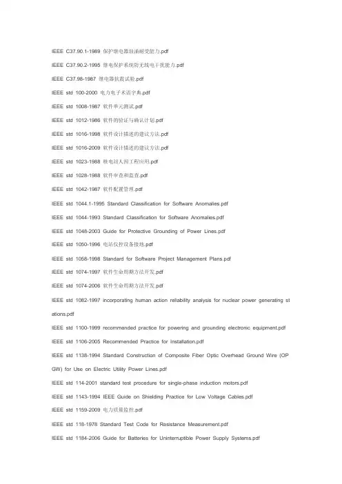
IEEE C37.90.1-1989 保护继电器浪涌耐受能力.pdfIEEE C37.90.2-1995 继电保护系统防无线电干扰能力.pdfIEEE C37.98-1987 继电器抗震试验.pdfIEEE std 100-2000 电力电子术语字典.pdfIEEE std 1008-1987 软件单元测试.pdfIEEE std 1012-1986 软件的验证与确认计划.pdfIEEE std 1016-1998 软件设计描述的建议方法.pdfIEEE std 1016-2009 软件设计描述的建议方法.pdfIEEE std 1023-1988 核电站人因工程应用.pdfIEEE std 1028-1988 软件审查和监查.pdfIEEE std 1042-1987 软件配置管理.pdfIEEE std 1044.1-1995 Standard Classification for Software Anomalies.pdfIEEE std 1044-1993 Standard Classification for Software Anomalies.pdfIEEE std 1048-2003 Guide for Protective Grounding of Power Lines.pdfIEEE std 1050-1996 电站仪控设备接地.pdfIEEE std 1058-1998 Standard for Software Project Management Plans.pdfIEEE std 1074-1997 软件生命周期方法开发.pdfIEEE std 1074-2006 软件生命周期方法开发.pdfIEEE std 1082-1997 incorporating human action reliability analysis for nuclear power generating st ations.pdfIEEE std 1100-1999 recommended practice for powering and grounding electronic equipment.pdf IEEE std 1106-2005 Recommended Practice for Installation.pdfIEEE std 1138-1994 Standard Construction of Composite Fiber Optic Overhead Ground Wire (OP GW) for Use on Electric Utility Power Lines.pdfIEEE std 114-2001 standard test procedure for single-phase induction motors.pdfIEEE std 1143-1994 IEEE Guide on Shielding Practice for Low Voltage Cables.pdfIEEE std 1159-2009 电力质量监控.pdfIEEE std 118-1978 Standard Test Code for Resistance Measurement.pdfIEEE std 1184-2006 Guide for Batteries for Uninterruptible Power Supply Systems.pdfIEEE std 1185-1994 installation methods for generating station cables.pdfIEEE std 1186-1996 阀控铅酸蓄电池维护、测试和更换.pdfIEEE std 1-2000 电子设备额定值中温度极限和电绝缘评定的一般原则.pdfIEEE std 1201-1991 工商业电缆托盘中使用的电缆的阻燃试验.pdfIEEE std 1205-2000 Guide for Assessing, Monitoring, and Mitigating Aging Effects of Class 1E E quipment Used in Nuclear Power Generating Stations.pdfIEEE std 1210-2004 Standard Tests for Determining Compatibility of Cable-Pulling Lubricants With Wire and Cable.pdfIEEE std 122-1985 Recommended Practice for Functional and Performance Characteristics of Co ntrol Systems for Steam Turbine-Generator Units.pdfIEEE std 1241-2000 Standard for Terminology and Test Methods for Analog-to-Digital Converters. pdfIEEE std 1249-1996 Guide for Computer-Based Control for Hydroelectric Power Plant Automation. pdfIEEE std 125-2007 Recommended Practice for Preparation of Equipment Specifications for Speed -Governing.pdfIEEE std 1283-2004 High-Temperature Operation on Conductors.pdfIEEE std 1289-1998 the application of human factors engineering in the design of computer-base d monitoring and control displays for nuclear power generating stations.pdfIEEE std 1313.2-1999 the application of insulation coordination.pdfIEEE std 1366-2001 Guide for Electric Power Distribution Reliability Indices.pdfIEEE std 1366-2003 Guide for Electric Power Distribution Reliability Indices.pdfIEEE std 1394.3-2003 Standard for a High Performance Serial Bus Peer-to-Peer Data Transport Protocol (PPDT).pdfIEEE std 141-1993 工业厂房电力分布.pdfIEEE std 1413.1-2002 Guide for Selecting and Using Reliability Predictions Based on.pdfIEEE std 1415-2006 Guide for Induction Machinery Maintenance Testing and Failure Analysis.pdf IEEE std 142-2007 Recommended Practice for Grounding of Industrial and Commercial Power Sy stems.pdfIEEE std 1434-2000 IEEE Trial-Use Guide to the Measurement of Partial Discharges in Rotating Machinery.pdfIEEE std 1559-2009 Standard for Inertial Systems Terminology.pdfIEEE std 15939-2008 Adoption of ISO-IEC 15939-2007—Systems and Software Engineering—Mea surement Process.pdfIEEE std 1633-2008 Recommended Practice on Software Reliability.pdfIEEE std 1800-2005 INTERNATIONAL STANDARD.pdfIEEE std 260.1-2004 Standard Letter Symbols for Units of Measurement (SI Units, Customary Inc h-Pound Units, and Certain Other Units.pdfIEEE std 270-2006 Standard Definitions for Selected Quantities, Units and Related Terms with Sp ecial Attention to the International System of Units.pdfIEEE std 279-1971 核电站保护系统准则.pdfIEEE std 281-1984 电力系统通讯设备使用环境.pdfIEEE std 295-1969 Standard for Electronics Power Transformers.pdfIEEE std 301-1988 用于电力辐照的探测器的放大器和预放大器的试验程序.pdfIEEE std 303-1991 recommended practice for auxiliary devices for motors in class 1, groups A, B, C, and D, division 2 locations.pdfIEEE std 308-1991 核电站1E级电力系统.pdfIEEE std 308-2001 核电站1E级电力系统.pdfIEEE std 315-1975(R1993) Standard American National Standard Canadian Standard Graphic Sy mbols for Electrical and Electronics Diagrams.pdfIEEE std 317-1983 核电站安全壳结构的电气贯穿件.pdfIEEE std 32-1972 Standard Requirements, Terminology,and Test Procedure for Neutral Grounding. pdfIEEE std 323-2003 核电站1E级设备的鉴定.pdfIEEE std 334-1994 核电站持续运行1E级电机的鉴定.pdfIEEE std 334-2006 核电站持续运行1E级电机的鉴定.pdfIEEE std 336-2005 核电站1E级仪表电气设备安装检测试验要求.pdfIEEE std 338-1987 核电站安全系统定期试验准则.pdfIEEE std 344-1987 核电站1E级设备抗震要求.pdfIEEE std 344-2004 核电站1E级设备抗震鉴定推荐方法.pdfIEEE std 352-1987 核电站安全系统可靠性分析原则.pdfIEEE std 37.91-2008 电力变压器继电保护导则.pdfIEEE std 379-2000 单一故障准则在核电站安全系统的应用.pdfIEEE std 381-1977 核电站使用的1E级模块的型式试验.pdfIEEE std 382-2006 核电站有安全功能的电动阀门组件的执行机构的资格鉴定.pdfIEEE std 383-2003 核电站1E级电缆垫片连接件型式试验.pdfIEEE std 384-2008 核电站1E级设备和回路的独立原则.pdfIEEE std 387-1995 核电站内柴油发电机组作为备用电源准则.pdfIEEE std 4-1995 Standard Techniques for High-Voltage Testing.pdfIEEE std 420-1982 核电站1E级控制盘的鉴定.pdfIEEE std 421.4-2004 Guide for the Preparation of Excitation System Specifications.pdfIEEE std 421.5-2005 Recommended Practice for Excitation System Models for Power System Sta bility Studies.pdfIEEE std 422-1986 核电站电缆系统的设计安装.pdfIEEE std 43-2000(R2006) Recommended Practice for Testing Insulation Resistance of Rotating M achinery.pdfIEEE std 450-1995 固定式应用排气铅酸电池的维护试验与更换建议方法.pdfIEEE std 484-1996 固定式应用排气铅酸电池安装设计与安装.pdfIEEE std 485-1997 固定式应用铅酸蓄电池尺寸确定的推荐措施.pdfIEEE std 493-2007 Recommended Practice for the Design of Reliable Industrial and Commercial Power Systems.pdfIEEE std 494-1974 核电站IE级设备与系统相关文件的标识方法.pdfIEEE std 495-1986 故障电路指示器的试验指南.pdfIEEE std 497-1981 核电站事故监控系统准则.pdfIEEE std 498-1990 核设施内测量和试验设备的标定要求.pdfIEEE std 516-2009 Guide for Maintenance Methods on Energized Power Lines.pdfIEEE std 525-1992 the design and installation of cable systems in substations.pdfIEEE std 528-1994 standard for inertial sensor terminology.pdfIEEE std 528-2001 standard for inertial sensor terminology.pdfIEEE std 535-1986 核电站1E级铅蓄电池的鉴定.pdfIEEE std 535-2006 核电站1E级铅蓄电池的鉴定.pdfIEEE std 572-1985 核电站1E级连接组件的鉴定.pdfIEEE std 572-2006 核电站1E级连接组件的鉴定.pdfIEEE std 576-1980 核电站控制室的设计.pdfIEEE std 577-2004 核电站安全系统的设计和运行中的可靠性分析要求.pdfIEEE std 603-1991 核电站安全系统准则.pdfIEEE std 622-1987 核电站电伴热系统的设计与安装.pdfIEEE std 627-1980 核电站内应用的安全系统设备的设计资格鉴定.pdfIEEE std 628-1987 核电站1E级电缆通道的安装与鉴定.pdfIEEE std 634-2004 Standard Cable-Penetration Fire Stop Qualification Test.pdfIEEE std 649-1991 核电站1E级马达控制中心的鉴定.pdfIEEE std 650-1990 核电站1E级静止电池充电器和逆变器的鉴定.pdfIEEE std 665-1995 电站接地导则.pdfIEEE std 666-2007 IEEE std Design Guide for Electric Power Service Systems for Generating St ations.pdfIEEE std 690-2004 核电站1E级电路的电线系统的设计与安装.pdfIEEE std 692-1986 核电站保卫系统准则.pdfIEEE std 730.1-1995 软件质量保证策划导则.pdfIEEE std 730-1989 软件质量保证计划.pdfIEEE std 730-2002 软件质量保证计划.pdfIEEE std 7-4.3.2-1993 核电站安全系统数字计算机准则.pdfIEEE std 7-4.3.2-2003 核电站安全系统数字计算机准则.pdfIEEE std 741-1997 核电站1E级电力系统和设备保护准则.pdfIEEE std 765-1995 核电站优先电源准则PSS.pdfIEEE std 796-1983 微机系统总线.pdfIEEE std 80-1986 交流变电站接地安全导则.pdfIEEE std 81-1983 Guide for Measuring Earth Resistivity, Ground Impedance.pdfIEEE std 828-1990 软件配置管理计划.pdfIEEE std 829-2008 软件测试文档.pdfIEEE std 830-1993 软件需求规格书建议方法.pdfIEEE std 833-1988 Recommended Practice for the Protection of Electric Equipment in Nuclear Po wer Generating Stations from Water Hazards.pdfIEEE std 837-2002 变电站永久接地质量标准.pdfIEEE std 845-1999 核电站人机界面性能评估.pdfIEEE std 933-1999 核电站可靠性大纲计划界定指南.pdfIEEE std 934-1987 核电站1E级设备部件更换件的要求.pdfIEEE std 944-1986 核电站内不间断电源的应用和试验.pdfIEEE std 946-1992 核电站辅助电源系统设计.pdfIEEE std 946-2005 核电站辅助电源系统设计.pdfIEEE std 982.1-1988 设计可靠的软件所采用的措施.pdfIEEE std 98-84 固体电绝缘材料热评估试验程序的编制.pdfIEEE std 99-2007 Recommended Practice for the Preparation of Test Procedures for the Thermal Evaluation of Insulation Systems for Electrical Equipment.pdfIEEE std 993-1997 Standard for Test Equipment Description Language (TEDL).pdfIEEE std ANSI N42.48-2008 American National Standard Performance Requirements.pdfIEEE std C2-2007 National Electrical Safety Code 2007 Edition.pdfIEEE std C37.013-1997 发电机出口断路器.pdfIEEE std C37.04-1999 Standard Rating Structure for AC High-Voltage Circuit Breakers.pdfIEEE std C37.04i-1991 Supplement to Standard Rating Structure for AC High-Voltage Circuit Brea kers Rated on a Symmetrical Current Basis.pdfIEEE std C37.100-1992 Standard Definitions for Power Switchgear.pdfIEEE std C37.101-1993 Guide for Generator Ground Protection.pdfIEEE std C37.101-2006 发电机接地保护指南.pdfIEEE std C37.111-1999 Standard Common Format for Transient Data Exchange (COMTRADE) fo r Power Systems.pdfIEEE std C37.20.1-1993 Standard for Metal-Enclosed Low- Voltage Power Circuit Breaker Switchg ear.pdfIEEE std C37.2-2008 Standard for Electrical Power System Device Function Numbers, Acronyms, and Contact Designations.pdfIEEE std C37.234-2009 Guide for Protective Relay Applications to Power System Buses.pdf IEEE std C37.30-1997 Standard Requirements for High- Voltage Switches.pdfIEEE std C37.34-1994 Standard Test Code for High-Voltage Air Switches.pdfIEEE std C37.48-2005 Guide for the Application, Operation, and Maintenance of High-Voltage Fus es, Distribution.pdfIEEE std C37.90.3-2001 Standard Electrostatic Discharge Tests for Protective Relays.pdfIEEE std C57.12.80-2002 电力分配变压器术语.pdfIEEE std C57.19.00-1991 Standard General Requirements and Test Procedure for Outdoor Power Apparatus Bushings.pdfIEEE std C62.23-1995 Application Guide for Surge Protection of Electric Generating Plants.pdf IEEE-EIA 12207.0-1996 Software Lifecycle Process.pdfIEEE-EIA 12207.1-1997 Software Lifecycle Process-Life cycle data.pdfIEEE-EIA 12207.2-1997 Software Lifecycle Process-Implementation considerations.pdf。
CDS:correlated double samplerVGA: variable gain amplifierAFE: AFE(Active Front End)整流/回馈单元的功能.其主动的含义在于,与传统的二极管或可控制硅整流技术相比,主动前端不再是被动地将交流转变成直流,而是具备了很多主动的控制功能。
它不仅能消除高次谐波,提高功率因数,而且不受电网波动的影响,具有卓越的动态特性。
ADC性能指标:直流性能:INL: 积分非线性误差。
指的是实际的传输特性与理想传输特性的在垂直方向上的最大差值,它表示了实际转移曲线偏离理想曲线的程度。
INL = | [(V D - V ZERO)/V LSB-IDEAL] - D |,其中0 < D < 2N-DNL: 微分非线性误差。
DNL = |[(V D+1- V D)/V LSB-IDEAL - 1] |,其中0 < D < 2N - 2较高数值的DNL增加了量化结果中的噪声和寄生成分,限制了ADC的性能,表现为有限的信号-噪声比指标(SNR)和无杂散动态范围指标(SFDR)。
抖动:交流分析方法:SNR:信噪比。
基频与耐克斯特频率以内的所有噪声信号(不包括基频的谐波)总和的比。
THD:总谐波失真。
基频与所有基频的谐波总和的比(dBc)。
IEEE规定至少要包含9次谐波。
SINAD:基频与耐克斯特频率以内的所有噪声和基频的谐波的总和只比。
SINAD反应了量化过程产生的噪声、非线性产生的噪声和其他噪声。
SFDR:无杂散动态范围。
基频的RMS值与最大谐波的值只比(dBc)。
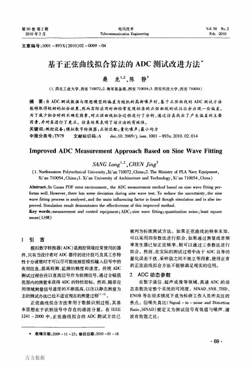
IEEE 1241-2000规定了用正弦波测试ADC性能的方法。
直流分析方法:FFT和直方图的比较:在低频输入下,由于输入近似直流,FFT不能起到多大作用。
我们关心的是ADC的输出有多大可信程度。
这时可以对ADC输入直流,分析ADC的输出数据的统计特性。
直方图:得到标准差。
CDS:correlated double samplerVGA: variable gain amplifierAFE: AFE(Active Front End)整流/回馈单元的功能.其主动的含义在于,与传统的二极管或可控制硅整流技术相比,主动前端不再是被动地将交流转变成直流,而是具备了很多主动的控制功能。
它不仅能消除高次谐波,提高功率因数,而且不受电网波动的影响,具有卓越的动态特性。
ADC性能指标:直流性能:INL: 积分非线性误差。
指的是实际的传输特性与理想传输特性的在垂直方向上的最大差值,它表示了实际转移曲线偏离理想曲线的程度。
INL = | [(V D - V ZERO)/V LSB-IDEAL] - D |,其中0 < D < 2N-DNL: 微分非线性误差。
DNL = |[(V D+1- V D)/V LSB-IDEAL - 1] |,其中0 < D < 2N - 2较高数值的DNL增加了量化结果中的噪声和寄生成分,限制了ADC的性能,表现为有限的信号-噪声比指标(SNR)和无杂散动态范围指标(SFDR)。
抖动:交流分析方法:SNR:信噪比。
基频与耐克斯特频率以内的所有噪声信号(不包括基频的谐波)总和的比。
THD:总谐波失真。
基频与所有基频的谐波总和的比(dBc)。
IEEE规定至少要包含9次谐波。
SINAD:基频与耐克斯特频率以内的所有噪声和基频的谐波的总和只比。
SINAD反应了量化过程产生的噪声、非线性产生的噪声和其他噪声。
SFDR:无杂散动态范围。
基频的RMS值与最大谐波的值只比(dBc)。
IEEE 1241-2000规定了用正弦波测试ADC性能的方法。
直流分析方法:FFT和直方图的比较:在低频输入下,由于输入近似直流,FFT不能起到多大作用。
我们关心的是ADC的输出有多大可信程度。
这时可以对ADC输入直流,分析ADC的输出数据的统计特性。
直方图:得到标准差。
ANSI/IEEE C62.33-1982(IEEE 1988年重定)(ANSI 1989年重定)美国国家标准关于浪涌保护器压敏电阻IEEE标准测试规范发起者浪涌保护器委员会IEEE电源工程协会1981年9月17日批准1988年3月10日重定1994年3月17日重定IEEE 标准版1983年7月1日批准1988年3月10日重定美国国家标准机构——————版权所有1982年条款页数1. 范围 (1)1.1 (1)1.2 (1)1.3 (1)1.4 (1)2.在定义压敏电阻里术语和字母符号的描述2.1额定参数值 (2)2.2 描述 (2)2.3 基本描述 (3)3.工作条件 (5)3.1 正常工作条件 (5)3.2 非正常工作条件 (6)4. 标准设计测试程序 (7)4.1 标准设计测试标准………………………………………………………………… ..74.2 统计程序 (7)4.3 测试标准 (7)4.4 限制电压测试(V c)(见Fig3) (7)4.5 额定峰值单次脉冲瞬时电流测试(I tm)(见图4) (8)4.6 寿命额定脉冲电流测试(见图3) (8)4.7 额定有效值电压测试(V m(ac))(见图5),额定直流电压测试(V m(dc)) (10)4.8 直流功耗电流测试(I D)(见图6) (10)4.9 标称压敏电压测试(V N(dc))和(V N(ac))(见图6) (11)4.10 额定循环峰值电压测试(Vpm)(见图5) (12)4.11 电容测试 (12)4.12 交流功耗功率(P d) (12)5.失效模式 (12)短路电路失效模式 (12)降级失效模式 (13)高限制电压失效模式 (13)“失效-安全”工作 (13)6.其他参数 (13)额定瞬变能量 (14)额定瞬时平均功率泄放(P t(A V)m) (14)电压过冲击(V os)(见图8) (15)响应时间,过冲持续时间(见图8) (15)7.参考书目 (15)1.总则1.1这个标准适用于浪涌保护应用系统的压敏电阻,该系统具有从直流到频率420Hz、电压小于等于1000Vrms,或者1200V dc。
IEC和IEEE浪涌防护标准文件比较相对于其它工业领域,浪涌防护行业出现时间尚不足百年。
在这样一个年轻的领域,人们对它的认识仍然存在着差异,而对于世界的各地的用户来说,如何选择合适的浪涌保护器就成为最为关心的问题。
目前,在浪涌保护行业中存在着两大标准制定机构,一个是国际电气技术委员会(IEC) ,另一个是电气电子工程师协会(IEEE)。
他们之间虽然既有相似之处,又存在差异。
本文将重点讲述两者之间的主要差异。
讲述的内容则分为浪涌保护的应用场所和产品特点两个方面。
作为国际机构,IEEE已经有很长的历史。
有关浪涌保护的标准文件为 ANSI/IEEE C62.41-48。
此标准文件对浪涌保护的各项应用规范做出了规定,其建议的测试波形考虑到了现实世界中电压及电流波动的实际情况,得到了广泛肯定。
IEEE有关浪涌保护的文件包括:C62.41.1 浪涌环境概述;C62.41.2 浪涌问题论述;C62.42 浪涌保护器元件;C62.44 浪涌保护器的应用;C62.45 浪涌保护器的测试;C62.48 系统互动。
一、浪涌保护器的测试波形的比较IEC和IEEE 采用的测试波形的整体比较:其中8/20 µs 波形用于短路电流测试,1.2/50 µs 波形和100 kHz 环波用于电压测试。
区别1:IEEE对于C,B类浪涌保护器的测试波形称为 8/20 混合波,其构成为1.2/50 µs 的开路电压测试,和8/20 µs的短路电流测试。
IEEE对于 A类保护器的测试波形为 100kHz的电压环波,用以模仿现实环境中配电系统内部产生的瞬态电压和电磁射频干扰。
执行环波测试的依据是:在现实的配电环境中,各类电气电子负载,如电机等传导性设备,逆变器,变频设备没,非线性电子设备,它们的开关和运作都会在线路造成瞬态电压,污染配电系统。
据研究表明,内部瞬态电压在配电系统的浪涌污染中占80%以上。
关键字:信号链ADC动态参数傅里叶序列作者:Bill Klein高级应用工程师德州仪器(TI)如同Bode 图是理解运算放大器(op amp) AC 参数的基础一样,傅里叶序列图是理解转换器AC 参数的基础。
在这两种情况下,幅度和相位与时间数据的关系就变为了幅度和相位与频率显示的关系。
因为必须要实现从模拟域到数字域的转换,因此对于转换器来说这种转换更为复杂。
而信号的傅里叶序列表现是用数学术语来进行充分描述的,无法在标准测试设备上实现。
因此,它不如Bode 图看起来直观。
当函数关系可以用一个数学表达式来描述时,时域中信号的标准傅里叶序列就可以被明确定义出来了。
但如果该函数仅为ADC的数字输出时,那么就需要快速傅里叶变换(FFT) 了。
该变换最早发表于1965 年,被称为Cooley-Tukey 算法,并被编写成为很多种计算机程序,此处的重要性在于结果。
这就得到了信号带宽中每个频率的幅度。
从这个结果中,您可以计算出若干个性能参数。
图1 给出了带有典型FFT 结果的图。
该图是从ADS8325 产品说明书上复制下来的,ADS8325是一款16 位250k 采样速率的转换器。
当输入为10kHz 频率的满量程正弦波时,FFT 显示出了在整个40kHz 范围内应用信号的每个整数倍频率时的峰值。
图1:ADS8325 输出的FFT 分析。
通过观察可以看出,在这个例子中,无杂散动态范围(SFDR) 大约为75dB,应用信号在10kHz 时为0dB,三次谐波在30kHz 时约为-75dB。
这是最大的寄生信号,SFDR 为两个幅度之间的差值。
因为确定ADC 输出的频率是不可能的,因此任何低于-75dB 的信号都必须被看成是噪声,并且被忽略掉。
式1这个公式也可被看成是dBc,其中dB 参考电平为载波信号或V0。
题目为《信号链基础知识:模拟与数字世界》的本系列文章的第三篇文章(2007 年11 月30 日发表)描述了与理想转换器相关的量子化噪声。
IEEE标准对互感器的要求1.概述1.1范围这个标准作为考察设备性能和互换性的基础,来帮助规范设备的选择,也用来作为安全规范。
这个标准覆盖了这种电器设备的导电性,尺寸和机械性能,也把安全因素,互感器的生产,变比,电流的最终分布作为纳入考虑因素。
1.2意图这个标准的意图是为电力系统和交流电以及电磁式电压互感器来提供一个性能规范。
这些互感器为户内和户外使用的。
2.参考文献3.定义3.1户内电压互感器:指的是因为其构造而必须保护该产品接触气候。
3.2开合式电流互感器:互感器有一个二次绕组与其他铁芯绝缘开来且永久组装在铁芯上但是没有一次绕组作为结构不可分割的一部分。
该类型的铁芯能偶打开或者分离这样他可以放置在一个一次导体上且可以安全重连。
它应有一个最小的绝缘用于2.5KV施加试验,且它能够或者不能够完全达到额定一次电压。
该类型主要用作一个临时的或者永久安装在哪里而实际上不破坏一次导体。
4.总要求4.1使用条件4.1.1正常温度和海拔使用条件符合这个标准的互感器应在他们适合的热等级下运行,并且海拔不超过1000m.4.1.1.1平均环境温度为30℃如果互感器使空气冷却的,那么冷却空气的环境温度不应超过40℃日平均环境温度不超过30℃,最低环境温度为-30℃。
4.1.1.2平均环境温度为55℃给出的互感器运行等级为55℃的平均温度,最高环境温度不超过65℃4.1.2 非正常温度和海拔使用条件互感器或许会应用在4.1.1中的高温或高海拔的条件下,性能会受到影响,其他特殊因素也应该给出。
4.1.3其他影响互感器设计和应用的条件上述未列出的非正常条件列入互感器设计和使用条件的考虑。
这种非正常条件如下:a)烟或气体,大量的或摩擦状的尘埃,爆炸混合性粉尘或气体,蒸汽,盐雾,大量的腐蚀性气体或水滴等。
b)不正常的震动,摇晃,或c)环境温度大于55℃或低于-30℃d)非正常运输或储存条件e) 不正常的空间限制或通风的限制f)非正常的灰尘,运行频率,维护的难度,波形匮乏,不平衡电压,特殊的安装要求。
IEEE 1241标准是一个关于电子设备中电源管理和系统管理的重要标准。
它提供了许多关于电源系统设计、性能和可靠性的指导原则。
以下是对IEEE 1241标准的800字回答:
一、简介
IEEE 1241标准是由电气和电子工程师协会(IEEE)发布的一系列电源管理标准,旨在规范电子设备的电源管理系统的设计和实施。
这些标准包括电源管理系统的性能、可靠性和可维护性等方面的要求。
二、主要内容
1. 电源管理系统设计原则
IEEE 1241标准强调了电源管理系统设计的重要性,包括电源电压的选择、电源系统的性能指标、电源转换效率、功率因数校正等方面。
此外,该标准还提出了电源系统的可靠性设计要求,包括过电流保护、过电压保护、过温保护等。
2. 电源管理系统的性能指标
IEEE 1241标准规定了电源管理系统的主要性能指标,包括电压精度、纹波抑制、瞬态响应、噪声抑制等。
这些指标对于确保电子设备的稳定运行和降低功耗具有重要意义。
3. 电源管理系统的可靠性和可维护性
该标准强调了电源管理系统的可靠性和可维护性,包括电源系统的故障检测和诊断、电源故障隔离、电源系统的备份和冗余等。
此外,该标准还提出了电源系统的可维护性要求,包括易于安装和拆卸、易于诊断和修复等。
三、应用场景
IEEE 1241标准适用于各种电子设备,如计算机、通信设备、消费电子产品、医疗设备等。
这些设备需要高效的电源管理系统来确保设备的稳定运行和降低功耗,从而提高设备的性能和可靠性。
四、优势和不足
IEEE 1241标准的优势在于它提供了一套统一的电源管理系统设计规范,有助于确保电子设备的电源管理系统的性能和可靠性。
此外,该标准还强调了电源管理系统的可维护性,有助于提高设备的可维护性和用户满意度。
然而,IEEE 1241标准也存在一些不足。
首先,该标准主要关注电源管理系统的设计和性能指标,而对于电源系统的成本和能耗等方面的考虑较少。
其次,该标准对于电源管理系统的安全性和电磁兼容性等方面的要求较少,需要其他标准和规范的支持。
五、结论
综上所述,IEEE 1241标准是一个重要的电源管理标准,对于电子设备的稳定运行和降低功耗具有重要意义。
该标准提供了一套统一的电源管理系统设计规范,有助于提高设备的性能和可靠性。
然而,该标准也存在一些不足,需要进一步完善和扩展。