热能与动力工程专业英语全部翻译译文
- 格式:pdf
- 大小:8.32 MB
- 文档页数:95

4.2 Refriger ant evaporators11Several ty pes of evapor ators c an be used in multistage systems.2A tubular, dir ect expansion evapor ator oil easily and requires the smallest refrigerant charge.3Where dir ect expansion is impr actical, a flooded system or a recirculated system may be used, but these methods c ompound oil r eturn pr oblems.24Some problems that can bec ome mor e acute in low-temper ature systems than in high-temperatur e sy stems include oil transport pr operties, loss off c apacity caused by static head from the depth of the pool of liquid r efrigerant in the evaporator, deterioration of refriger ant boiling heat tr ansfer c oeff icients, and higher specif ic volumes for the vapor.35The effect of pressure losses in the evapor ator and suc tion piping is mor e acute in lowtemperatur e sy stems because of the lar ge change in satur ation temperatures and specif ic volume in relation to pr essur e changes at these c onditions.6Sy stems that oper ate near zero absolute pressure are particularly affected by pressur e loss.7F or example, with R-12 and R-22 at 140 kPa suction and 27℃liquid feed temper ature, a 7 kPa loss incr eases the volume flow r ate by about 5﹪.8A t 35 kPa suction and -7℃ liquid feed temperature, a 7 kPa loss increases the volume flow rate by about 25﹪.49The depth of the pool of boiling r efrigerant in a flooded evaporator causes a liquid head or static pressur e that is exerted on the lower part of the heat transfer surfac e.10Therefore, the saturation temperatur e at this sur face is hi gher than the pr essure in the suction line, which is not affected by the static head.11A lthough tubular dr y expanded evaporators do not have appreciable static liquid head, gas pressur e dr ops from the inlet to the outlet of the evaporator create a velocity head that c auses a similar condition.512The liquid depth penalty for the evaporator can be eliminated if the pool of liquid is below the heat transfer surface and a r efrigerant pump spr ays the liquid over the surface.13Of course, the pump energy is an additional heat load to the system, and more refrigerant must be used to prov ide the Net Positive Suction Head (NPSH) requir ed by the pump.14The pump is also an additional item to be maintained.615Another type of low-temperatur e evaporator is the flash cooler in w hic h liquid refrigerant is cooled by boiling off some vapor.16The r emaining cold liquid c an then be pumped from the flash c ooler to the evaporator.17There it is either top or bottom fed at a r ate greater than the evapor ation rate to ensure wetting of the entire evaporator surface for maximum heat tr ansfer without an appreciable static head penalty.18This liquid over feed system is fr equently used in large refrigerated war ehouses with many evapor ators. 719Another less frequently used system pumps the liquid r efrigerant as a secondar y cooler, or coil, heat transfers to it from the material being cooled.20The liquid temperature rises to develop a temper ature r ange, but bec ause pr essur e is maintained suff iciently above satur ation by the liquid pump, the coolant does not evapor ate until it returns via a restriction to the flash cooler.21Suff icient refriger ant must be circ ulated to acc ommodate the temperatur e range.22The flash c ooler in this sy stem is an acc umulator r eceiver similar to that used in a liquid overfeed system, except that no excess r efrigerant is fed to the remote heat transfer surfac e.823In both types of liquid r ecirculation systems, the cold liquid can be moved by mec hanic al pumps or by pressure from the compr essor dischar ge. 4.2制冷剂的蒸发器11有几种类型的蒸发器,可用于在多级系统。
毕业设计外文翻译原文标题:Proposal for a high efficiency LNGpower-generation System utilizing wasteheat from the combined cycle中文标题:一个高效的利用液化天然气联合循环余热的发电系统学院名称:能源与动力工程学院专业名称:热能与动力工程Proposal for a high efficiency LNG power-generation system utilizing waste heat from the combined cycleY. Hisazumi*, Y. Yamasaki, S. SugiyamaEngineering Department, Osaka Gas Co., 1-2 Hiranomachi 4-chome Chuo-ku, Osaka 541, Japan Accepted 9 September 1998AbstractHigh-efficiency power-generation with an LNG vaporizing system isproposed: it utilizesthe LNG's cold energy to the best potential limit. This system can be applied to LNG vaporizers in gas companies or electric power companies and recovers the LNG's cold energy as electric power. The system consists of a Rankine cycle using a Freon mixture, natural-gas. Rankine cycle and a combined cycle with gas and steam turbines. The heat sources for this system are the latent heat from the steam-turbine's condenser and the sensible heat of exhaust gas from the waste-heat recovery boiler. In order to find out the optimal condition of the system, several factors, such as gas turbine combustion pressure, steam pressure, condensing temperature in combined cycle, composition of mixture Freon, and natural gas vaporizing pressure are evaluated by simulation. The results of these studies show that in the total system, about 400 kWh can be generated by vaporizing 1 ton of LNG, including about 60 kWh/LNG ton recovered from the LNG cold energy when supplying NG in 3.6 MPa.. About 8.2MWh can be produced by using 1 ton of LNG as fuel, compared with about 7 MWh by the conventional combined system. A net efficiency of over 53%HHV could be achieved by the proposed system. In the case of the LNG terminal receiving 5 million tons of LNG per year, this system can generate 240 MW and reduce the power of the sea water pump by more than 2MW. 1998 Elsevier Science Ltd. All rights reserved.1. IntroductionIn the fiscal year 1994, the amount of LNG imported to Japan reached about 43 million tons; of this 31 million tons were used as fuel for power generation. As shown in Fig. 1, about 20% of the LNG imported was used for power generation [2]. Fig. 2 shows the major LNG power generation systems now in operation and their outputs. Several commercial LNG power generation plants have been constructed since 1979, and their total output has reached approximately 73 MW. Among the new power-generation plants without CO2 emission, this value of 73 MW is second to the 450 MW input of geo-thermal power generation plants in Japan, with the exception of power generation by refuse incinerators, and is much larger compared with the 35 MW output of solar-power plants and the 14 MW output of wind-power stations.Table 1 shows the LNG power generation plants constructed in Japan. The economics of LNG power generation became worse as the appreciation of the yen madethe cost of energy kept constant but while raising the construction cost; the adoption of the combined cycle utilizing gas-turbine and steam turbine (hereafter called combined cycle) increased the gas send-out pressure and lowered the power output per ton of LNG. Therefore, no LNG powergeneration plants were constructed in the 1990s due to lower cost effectiveness of the systems.As for the thermal power plant using natural gas as fuel, the steam turbine produced only about 6 MWh of power output per ton of LNG. But recently, improvement in blade-cooling technology and materials of the gas turbine enabled a 1400℃class turbine to be designed and increased the combustion pressure up to 3 MPa. Therefore, as shown in Fig. 3, the heat efficiency of the combined cycle has been improved and the electrical output from 1 ton of LNG has reached about 7MWh.In this paper, a proposal is made for the high-efficiency LNG power generation system based on a new concept which fully utilizes the cold energy without discarding it into the sea. The system is composed of the combined cycle and the LNG power-generation plant.2. High-efficiency LNG power-generation system2.1. Basic componentsFig.4 shows the process flow diagram of the high-efficiency LNG power-generation system. This complex system consists of the combined cycle and the LNG power generation cycle. The combined cycle is composed of a gas turbine (GAS-T) and a steam turbine (ST-T) using natural gas (NG) as fuel, while the LNG power generation cycle is composed of a Freon (uorocarbon) mixture turbine (FR-T) and a natural-gas turbine (NG-HT, NG-LT) using the latent heat of condensation from the exhaust steam and the sensible heat of the exhaust gas as heat sources. The plate fin type heat exchanger can be used for the LNG/natural gas (LNG-CON) and LNG/ Freon mixture (FR-CON). The shell-and-tube type can be selected as exchangers for exhaust steam/natural gas (LNG-VAP),exhaust steam/Freon mixture(FR-VAP), and exhaust gas/natural gas (NG-SH) applications according to the operating conditions.Ice thickness on the surface of the heat-exchanger tubes becomes a problem as heat is exchanged between exhaust gas and cold natural gas or Freon mixture. The ice thickness can be estimated by the technology of heat transfer between LNG and sea water, thus enabling one to avoid blockages due to ice inside the tubes.In addition, stable and continuous send-out of gas is made possible by using a bypass system, even if turbines and pumps for the Freon mixture and natural gas circulating systems (FR-RP, LNG-RP) stop.2.2. Features of the systemThe practical use of the following existing technologies in combination shows the high feasibility of the proposed system:. Power generation using Freon or hydrocarbon type Rankine cycle,. Power generation by natural-gas direct expansion],. TRI-EX type vaporizer which vaporizes LNG by using an intermediate medium or vacuum type LNG vaporizer.The Freon mixture is made up of the HFC type, which is a fluorocarbon consisting of H, F, and C and has no adverse influence on the ozone layer; it enables reduction in exergy loss at the heat exchanger and increases itscirculating flow rate to be achieved.The effective recovery of cold exergy and pressure exergy is made possible by the combined system using natural gas and Freon mixture Rankine cycle.Fig. 5 shows the temperature-heat duty relation when vaporizing 1 kg of LNG in the system shown in Fig. 4. Separation of the condensed natural-gas in two sections enables an increase in the heat duty between Freon (FR) and LNG, and a reduction of difference in temperature of LNG and natural gas between the inlet and outlet of the heat exchanger.3. Evaluation of the characteristics of the proposed system3.1. Process simulationThe characteristics of this system were evaluated by using process simulator. The followings are the conditions used for the calculation:Effciencies of rotating machines LNG compositionGas turbine (GAS-T) 88% CH4 89.39%Steam turbine (ST-T) 85% C2H6 8.65%Natural-gas turbine (NG-HT, LT) 88% C3H8 1.55%Freon turbine (FR-T) 88% iC4H10 0.20%Air compressor (AIR-C) 85% nC4H10 0.15%LNG pump (LNG-MP, RP) 70% iC5H12 0.01%Freon pump (FR-RP) 70% N2 0.05%Natural gas gross heat-value: 10,510 kcal/Nm3AIR/NG flow ratio of gas turbine: 323.2. Effects of send-out pressure of the natural gasWhen natural-gas is sent out at 3.5 or 1.8 MPa, evaluations were made of the effects of send-out pressure of the LNG and change in superheating temperature of the natural gas on the total output of the high pressure (NG-HT) and the low pressure (NG-LT) natural-gas expansion-turbines. Fig. 6 shows the results of this calculation, where self consumption of power is calculated from the power, raising the pressure of the LNG up to the inlet pressure of the turbine minus the power required for the original send-out pressure. In both cases, the inlet pressure rise for the turbine causes an increase of self consumption power, but brings about a greater out-put. About 7 MPa of the inlet pressure of the turbine is appropriate considering the pressure tolerance of the heat exchangers.When the superheating temperature of the natural gas at the inlet to the turbine becomes high, the recovery of power increases, but the temperature of the exhaust gas from the outlet of the natural-gas super heater (NG-SH) declines, thus indicating that there is a limitation to superheating gas.3.3. Effects of combustion pressure of the gas turbineThe outputs of the gas turbine and the steam turbine, and the efficiency per gross heating value were evaluated by changing the combustion pressure of the gas turbine operating at 1300℃turbine-inlet temperature - see Fig. 7.If the combustion pressure of the gas turbine becomes high, the output of the gas turbine increases, but the output of the steam turbine decreases because the rise in combustion pressure causes a lowering of the exhaust-gas temperature at the outlet of the gas turbine and consequently a decline in the steam temperature at the inlet of the steam turbine. However, the overall efficiency of the turbines increases upon increasing the combustion pressure because the increment of gas-turbine output exceeds the decrement of steam turbine output. As a result, taking the pressure loss into account, it is appropriate to set the send-out pressure of the natural gas at the LNG terminal at 3.5 MPa.(FR-vap),3.4. Effects of Inlet pressure of the steam turbineFig. 8 shows the relations between the steam-turbines output and exhaust gas temperatures by changing the steam pressure in the range of 3-7 MPa. As the steam pressure increases, the output of the steam turbine rises and the temperature of the exhaust gases also increase. Besides, the power required for the water-supply pump increases with a rise in the steam pressure. Therefore, the current combined cycles operate at steam pressure of 7 MPa or more because the increment of the output of steam turbine exceeds the additional power required for the water-supply pump.3.5. Rankine cycle using a Freon-mixture refrigerant.The Freon refrigerant was selected from the HFC refrigerants on the basis of marketability, boiling point and freezing-point. Table 2 shows the physical properties of HFC Freon.When only HFC-23 is used as the medium, because of its low freezing-point it never freezes even if heat is exchanged between the LNG and HFC-23. But if HFC-23 is heated by the exhaust steam of the steam turbine, the pressure rises approximately up to the critical pressure. Therefore, the use of HFC-23 is not cost effective, because it is then necessary to set a high design pressure. To cope with this problem, we evaluated the compound refrigerant composed of HFC-134a (with high boiling point) and HFC-23.Fig. 9 shows saturated vapor pressure at various temperatures, the boiling point and the dew point at atmospheric pressure for mixtures of HFC-23 andHFC-134a of various compositions. The saturated pressure at each temperature rises with the increasing mole ratio of HFC-23: Hence, 40-45% of the mole ratio of HFC-23 is the optimal value considering the design pressure of the equipment.Fig. 10 shows the plots of the output of the Freon turbine versus the condensing temperature of the steam turbine when changing the composition of the HFC-23. In this figure, the turbine outlet pressure is determined in such a way that thedifference in temperature between the LNG and Freon mixture is not less than 5℃in the Freon condenser (FR-CON). The Freon turbine's inlet-pressure is set to the saturatedtemperature of the Freon mixture, i.e. less than 2℃from the steam-condensing temperature.This figure indicates that the output of the turbine scarcely correlates with the mole ratio of HFC-23. The higher the steam-condensing temperature becomes, the greater the output per ton of LNG the turbine produces, but in such a case, it is necessary to evaluate the system as a whole because more fuel is required, as described below. The result indicates that the optimal mole composition of HFC-23 and HFC-134a is 40%/60% considering both design pressure and the output of the turbine.3.6. Comprehensive evaluation from the viewpoint of the steam-condensing Temperature.As the dew point of the exhaust gas is 42℃, it is wise to set the exit temperature of the exhaust gas from the natural-gas super heater (NG-SH) to 80℃or more in order to prevent white smoke from the smoke stack. Table 3 shows the effect of the steam-condensing temperature on the generated output of the total system. The lower steam-condensing temperature brings about a higher efficiency of the total system, but also causes a lowering in the inlet temperature of natural-gas turbine. Therefore, it is appropriate to set the steam-condensing temperature at approximately 30℃.When the condensing temperature is 30C, the generated outputs per ton of LNG of the combined cycle and LNG power generation plant are 342.83 and67.55 kWh, respectively, resulting in 402.64 kWh of total generated output aftersubtracting the self-use power. As 48.94 kg of fuel is used for operating the system, the generated outputs of the combined cycle and the total system reach about 7 and 8.2 MWh, per ton of fuel respectively.3.7. Evaluation of exergyNatural-gas is liquefied at an LNG liquefaction terminal, with the consumption of about 380 kWh/LNG-ton: 1 ton of LNG having about 250 kWh of physical exergy as cold exergy and 13.5 MWh of chemical exergy. Fig. 11 shows the result of evaluating the exergy of the system shown in Fig. 4 under the optimal condition. The total output of Freon and natural gas turbines is 67.5 kWh, and the effective recovery percentage of cold exergy is 56%. As 90 kWh out of the pressure exergy can be recovered as output, about 157 kWh of net recovery can be obtained, which indicates the recovery percentage reaches about 63% for 250 kWh of LNG cold exergy. This conversion efficiency is higher than that achieved from chemical exergy to electric power.Most of the exergy loss occurs in the heat exchanger and the turbine, and in mixing with re-condensed LNG. As for the turbines, the loss of energy may be improved by using high-efficiency turbines. On the other hand, modification of the heat exchanger to reduce the energy loss may cause increased complexity of the system and is difficult to be done from the economic viewpoint. Though the recovery.percentage of cold energy in this system is low compared with the 80% in air-separation equipment, this system has the advantage of recovering a large amount of the available cold energy.4. ConclusionThe paper has proposed a high-efficiency LNG power generation system in combination with a combined-cycle power generation system fueled by natural-gas. The system utilizes LNG cold energy and it requires no sea water as a heat source.This system can be applied to LNG vaporization and send-out processes of gas companies or electric-power companies. The system recovers LNG coldenergy as an electric-power output without wasting it into sea water. The system consists of Rankine cycle with Freon mixture and a natural-gas Rankine cycle using the latent heat of exhaust steam from the steam turbine and the sensible heat of exhaust gas from the waste-heat recovery boiler. To improve the total efficiency of the system, a simulation was conducted to evaluate several factors, such as the composition of the Freon mixture, natural gas send-out pressure, as well as the combustion pressure steam inlet pressure, and steam-condensing temperature of the combined cycle. As a result, not less than 60 kWh/LNG-ton of output was generated even at a high natural-gas send-out pressure of 3.5 MPa. This value is considerably higher than the output generated at a LNG send-out pressure of 3 or 4 MPa, as given in Table 2.The system can produce about 400 kWh of net output when vaporizing 1 ton of LNG. While the conventional combined-cycle system in operation generates about 7 MWh when 1 ton of LNG is used as fuel, the system using the same amount of fuel generates about 8.2 MWh with a high degree of efficiency: a not-less-than 53% conversion efficiency was achieved per gross heat value.In the case of an LNG terminal receiving 5 million tons of LNG per year, this system can generate a power of about 240 MW when 600 t of LNG is used in an hour. With the elimination of about 24,000 tons per hour of sea water, which has been used for vaporizing 600 t/h of LNG in the conventional system, no less than 2 MW of electric power for operating sea water pumps can be saved.The proposed system emits no CO2, and can generate a large amount of electricity with high cost efficiency when incorporated into a combined cycle, with no use of sea water. Therefore, we consider that installation of this system is the one of the most favorable means of investment to put a new energy source or energy-saving equipment to practical use.To realize the full potential of this system, it is necessary to understand the heat characteristics of the Freon mixture, the icing and heat transfer characteristics of exhaust steam, the controllability of total system and the characteristics against partial load.References[1] The Center for Promotion of Natural gas Foundation. Research and development report of cold energy utilizing system, 1994[2] Japan's Energy and Economy Research Center. Energy and economy statistical data in 1995[3] Abe. Operating results and future prospect of a recent combined-cycle power generation plant. Thermal and Nuclear Power 1995;46(6):33-41[4] Maertens J. Design of Rankine cycles for power generation. Int. Refrig. 1986;9:137-43[5] Terada, Nakamoto. Power generation utilizing LNG cold. Thermal and Nuclear Power Generation 1986;37(10):66-71[6] Ooka, Ueda, Akasaka. Advanced LNG vaporizer and power generation utilizing LNG cold. Chemical Engineering 1981;45(3):187-90[7] Miura. The development of LNG vaporizer using vacuum steam heat (VSV). Journal of Japan Gas Society 1992;45:34-6[8] Nagai. Software-package and the usage. Chemical Equipment1994;August:31-7[9] Daikin Co. Ltd. Freon Data Sheet of HFC23一个高效的利用液化天然气联合循环余热的发电系统日本大阪541燃气有限公司工程部1-2平野町4肖梅中央谷,1998年9月概述本文提出了一个高效液化天然气气化发电系统,它是利用液化天然气冷能的最佳潜能极限。
Every free surface emits energy in the form of electromagnetic waves;the amount of energy is a function of the surface temperature. This emitted energy is known as radiant thermal energy. The nature of this radiant energy is not completely understood, but laws have been formulated that describe its behavior. It is recognized that, as with other forms of radiant energy ,radiant heat energy is transmitted in the form of electromagnetic waves. The complete formulation of the laws governing radiant heat energy must consider that this energy is quantized,that is, the energy is transferred in quanta. In contrast with other modes of heat transfer, no medium is required to transmit radiant energy. In fact some gases, for instance, carbon dioxide and water vapor, absorb some of the radiant energy passing through them.每一个自由表面都会以电磁波的形式发射能量,能量的量是表面温度的函数。
6.1‟s most efficient speed is usually much higher than that of the machine it is driving ,so a speed reduction gear usually has to be used .600 000马力的汽轮机。
转子——叶轮上装有动叶,转子两端装有轴颈。
轴承箱——安装在气缸上,用来支承转子的轴。
调速器和阀门系统——通过控制蒸汽流量来调节涡轮的速度和出力,同时还有轴承润滑系统以及一套安全装置。
某种类型的联轴器——用来连接从动机械…catch ‟the steam from the nozzle smoothly ,and they are curved so that they change the direction of the jet and in so doing receive an impulse which pushes6.1(见原文)所示为一种简单的冲动式汽轮机。
…reaction ‟ turbine .moving blades are also nozzles ,similar to the stationary nozzles but facing the other way ,and in addition to catching and deflecting the steam issuing from the stationary(见原文中图6.2)它综合了冲力和反作用力的原理。
6.2中的涡轮壳带有一整圈喷嘴,这些喷嘴和反冲式涡轮机里的一样,也是弯曲的,并以最有效的角度引导蒸汽喷向转动的叶片。
,under these conditions the exhaust volume flow becomes large ,and it is necessary to have more than one exhaust stage ;for example ,a large turbine may have three are“axial flow ”turbine .“double flow ”.drops can damage the blades and reduce the turbine efficiency ,and this is one reason why the steam ,after passing through the high-pressure turbine ,idea sometimes。
2.5 Natural Convectionnatural or free convection.therefore important not to ignore radiation in calculating the total heat loss or gain.wall temperatures in a room can affect human comfort.(1)gravity coils used in high humidity cold storage rooms and in roof-mounted refrigerant condensers,(2)the evaporator and condenser of household refrigerators, (3) baseboard radiators and convectors for space heating and(4)cooling panels for airdifference in density of the adjacent fluid.diffusion.β, the kinematic viscosity ν (=μ/ρ) ,and the thermal diffusivity α=(κ/ρc p )., Nu, is a function of the product of the Prandtl number ,Pr ,and Grashof number ,Gr, which ,when combined ,depend on the fluid properties ,,Δt ,and the characteristic length of the surface ,L.divided into three regions: (1) turbulent natural convection for which n equals 0.33, (2) laminar natural convection, for which n equals 0.25 and (3) a region that has ( Gr·Pr) less than for laminar convection, for which the exponent n gradually diminishes from 0.25 to lower values.Pr) is likely to be very small, so that the exponent n is 0.1.Pr) to find whether the boundary layer is laminar or turbulent, then apply the appropriate equation.transfer coefficient is independent of the characteristic length., the heat transfer coefficient for vertical pipes islarger than for horizontal pipes.facing upward can be used.for natural convective heat transfer coefficients indicate that caution should be taken when applying coefficients for (isolated) vertical plates recommended by ASHRAE for situations with vertical surfaces in enclosed spaces (buildings).correlations for calculating natural convective heat transfer from vertical surfaces in rooms undercertain temperature boundary conditions have been developed.the forced convection effect, i.e. , the Reynolds number , increases, the“mixed convection”(superimposedcombined free and forced convection heat transfer .tubes.conditions influence the values of the convection coefficient in a mixed convection regime, but the references permit locating the pertinent regime and approximating the convection coefficient.。
热能与动力工程Thermal Energy and Power Engineering材料与能源学院:Institute of Materials and Energy空调制冷:refrigeration and air conditioning热传导:thermol conduction学生毕业后能胜任现代火力发电厂,制冷与低温工程及相关的热能与动力工程专业的技术与管理工作,并能从事其它能源动力领域的专门技术工作.The graduates may find employment of technology and management in the fields of the Thermal Energy &Power Engineering (TEPE) and its relevance, such as modern power plant or the Refrigeration and Cryogenics Engineering (RCE), the graduates may also engaged in the special technique in the fields related to TEPE.现代空气动力学、流体力学、热力学、水力学以及航空航天工程、水利水电工程、热能工程、流体机械工程都提出了一系列复杂流动问题,其中包括高速流、低速流、管道流、燃烧流、冲击流、振荡流、涡流、湍流、旋转流、多相流等等A series of complicated flow problems have been posed in modern fluid mechanics, aero dynamics, thermodynamics, and aeronautical and aerospace engineering, water conservancy and hydropower engineering, heat energy engineering, fluid machinery engineering, and so on, and they cover high-speed flow, low-speed flow, eddy flow, turbulent flow, burning flow, impact flow, oscillating flow, backflow, and two-phase flow, etc.In the thermal engineering, the studied objects normally are isolated from one another and then we try to analysis the change and interaction, the studied objects isolated is named thermodynamic system.在热力工程中,通常将研究对象分离出来再分析其变化及(与外界)的相互作用,该对象即热力系统。
4.8The major pieces of equipment required to complete the air-conditioning cycle are listed as follows:①Fan. ②Supply ducts.③Supply outlets.④Space to be conditioned.⑤Returnoutlets.⑥Returnducts.⑦Filter.⑧Heating coil(Combustion chamber) or cooling coil.完成空调循环的主要设备如下所示:风机,送风管,送风口,被调空间,回风口,过滤器,加热盘管(燃烧室)或冷却盘管。
The purpose and function of each of these components are covered in the following sections.这些组成部件中的每一个的目的和用途在下面的文章中都将会涉及到。
Fan 风机The fan moves air to and from an enclosed space. In an air-conditioning system,the fan moves air that consists of:①All outdoor air.②All indoor or room air(This is also called recirculated air).③A combination of outdoor and indoor air.风机的作用是吧空气引入或引出密闭的空间。
在空调系统中,风机所输送的空气包含:室外空气,室内空气(也叫循环空气),室内外混合空气。
The fan pulls air from the outdoors and from the room at the same time. Since the drafts in the room cause discomfort, and poor air movement slows the tody heat rejection process, it is necessary to regulate the amount of air supplied by the fan. To accomplished this regulation, a fan is selected that can deliver the correct amount of air. By controlling the speed of the fan, the air stream in the room can be regulated to provide good circulation without drafts.风机从室外引入空气,同时把室内空气排出,由于室内吹风会产生不舒适,空气稀薄时会减慢热流动过程。
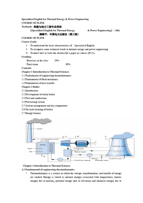
Specialized English for Thermal Energy & Power EngineeringCOURSE OUTLINETextbook: 热能与动力工程专业英语(Specialized English for Thermal Energy & Power Engineering)(3th) 阎维平,中国电力出版社(第三版)COURSE OUTLINECourse Goals:1.To understand the basic characteristics of Specialized English.2.To recognize some technical words in thermal energy and power engineering.3.To know how to write the abstract for a paper or a thesis (P155).Grading:Exercises in the class 20%Final exam 80%ContentsChapter 1 Introduction to Thermal Sciences1.1 Fundamental of engineering thermodynamics1.2 Fundamental of fluid mechanics1.3 Fundamental of heat transferChapter 2 Boiler2.1 Introduction2.2 Development of utility boiler2.3 Fuel and combustion2.4 Pulverizing system2.5 System arrangement and key components2.6 On-load cleaning of boilers2.7 Energy balanceChapter 1 Introduction to Thermal Sciences1.1 Fundamental of engineering thermodynamics•Thermodynamics is a science in which the storage, transformation, and transfer of energy are studied. Energy is stored as internal energy( associated with temperature), kinetic energy( due to motion), potential energy (due to elevation) and chemical energy( due tochemical composition); it is transformed from one of these forms to another; and it is transferred across a boundary as either heat or work.第一章热科学介绍1.1 工程热力学基础热力学是一门研究能量储存、转换及传递的科学。
4.4 Absorption Heat Pump吸收式热泵(4·4)Functions Of Absorption Heat Pump 1.吸收式热泵的功能An absorption heat pump extracts heat from a low- temperature heat source ,such as waste heat or surface water ,and delivers its heat output at a higher temperatur for winter heating or Other applications at a coefficient of performance greater than 1 .吸收式热泵从低温热源(如废热或地表水)取热,在较高的温度下输出热量用于冬天或其他场合供热,其效能系数大于1。
In Japan and Sweden ,absorption heat pumps have been installed in dustrial and district heating plants using industrial waste heat to pmvide hot water ,typically at 165 。
F ,for winter heating or other purposes at a COP between 1 ·4 and l. 7 ·在日本和瑞典,吸收式热泵已经安装于利用工业废热来提供热水的供热工厂(代表性的温度是165F),用于冬天供热或其他用途,其COP(效能系数)在1·4~1·7之间。
Absorption heat pumps can be used either for winter heating or for cooling in summer and heating in winter ·吸收式热泵单向用于冬天供热或双向用于夏天制冷、冬天供热。
4.5 Comfort and DiscomfortOne of the goals of the environmental engineer and architect is to ensure comfortable conditions in a building.Thermal pleasure can only be achieved locally over part of the body or temporarily in the context of a situation which is in itself uncomfortable.We are left simply with the idea of comfort as a lack of discomfort;this may seem an uninspiring definition,but nevertheless it presents a real practical challenge.环境工程师和建筑工程师的目标之一就是确保一栋建筑物具有舒适的环境。
热愉悦性只有身体的局部才能感觉到,或者是在一本身并不舒适的环境下暂时达到。
一连几个小时连续的热预约是不可能的,我们认为舒适就是只要不感到不舒适就可以了。
这好像是一个很平常的定义,但是不管怎么说,它提出了一个现实的挑战。
General thermal discomfort will be felt if a person is either too hot or too cold.In addition there are several potential sources of local discomfort ,such as cold feet or draughts .假如一个人觉得太热或者太冷,通常就会觉得热不舒适。
除此之外,还有几个造成不舒适的来源,比如说脚冷或者吹风。
4.7Hand-over and documentationDesigners and contractors can help to ensure adequate maintenanceby stressing its importance to the client. The client should be advisedabout the personnel required and provided with the requisite infonnationfor maintenance. 设计者和承包商通过对用户强调维修的重要性来保证足够的维修。
应当向用户建议所需要的人员,并提供必要的信息以进行维修。
For plant to continue working properly throughout its life it isnecessary for the maintenance and operating staff to be familiar with theprinciples and methods of running the plant. In addition to a full set ofrecord drawings, two manuals should be available, one for the operatingstaff (e.g. office manager, caretaker) and another for the maintenancestaff. The fonmer should describe such things as the design principles,the method of operation, details of alarms and safety precautions. Thelatter, larger service manual, should contain the information listed by BS5 720: 1 979 and reproduced below. 为使设备在整个使用期限内连续正常工作,维修和操作人员必须熟悉设备、运转原理和操作方法。
热能与动力工程专业英语-翻译(李瑞扬)1.3 The Characteristics of Fluids 流体的特征constituent:组成的;tangential:切向的;restrain:限制、约束;equilibrium:平衡,均衡;interface:相互关系、分界面;molecule:微小颗粒、分子;continuum:连续体;vessel:容器;tar:焦油、柏油;pitch:树脂;imperceptibly:察觉不到的,细微的;restore:恢复;subside:下沉、沉淀、减退、衰减;hypothetically:假设地、假想地;sphere:球、球体;microvolume:微元体积;rarest:最稀罕的,虽珍贵的A fluid is a substance which may flow; that is, its constituent particles may continuously change their positions relative to one another. Moreover, it offers no lasting resistance to the displacement, however great, of one layer over another. This means that, if the fluid is at rest, no shear force (that is a force tangential to the surface on which it acts )can exist in it. A solid, on the other hand, can resist a shear force while at rest; the shear force may cause some displacement of one layer over another, but the material does not continue to move indefinitely. In a fluid, however, shear forces are possible only while relative movement between layers is actually taking place. A fluid is further distinguished from a solid in that a given amount of it owes its shape at any particular time to that of a vessel containing it, orto forces which in some way restrain its movement. 流体是可以流动的物质,也就是说,组成流体的质点可以连续的改变它们的相对位置。
热能与动力工程专业英语第四版以下为您提供 20 个关于热能与动力工程专业的英语释义、短语、单词、用法及双语例句:1. **Thermal Energy and Power Engineering**:热能与动力工程- 释义:This term refers to the field that studies and applies technologies related to thermal energy conversion and power generation.- 例句:I'm majoring in Thermal Energy and Power Engineering at the university.(我在大学主修热能与动力工程。
)2. **Heat Transfer**:热传递- 释义:The process by which heat is transferred from one place to another.- 例句:Heat transfer is an important concept in thermal engineering. (热传递是热能工程中的一个重要概念。
)3. **Thermal Efficiency**:热效率- 释义:The ratio of the useful heat output to the total heat input in a thermal system.- 例句:Improving thermal efficiency is a key goal in power generation. (提高热效率是发电的关键目标。
)4. **Power Generation**:发电- 释义:The process of producing electrical power.- 例句:Different methods of power generation have their own advantages and disadvantages. (不同的发电方法各有优缺点。
4.3Refrigeration 制冷Refrigeration was used by ancient civilizations when it was naturally available. The Roman rulers had slaves transport ice and snow from the high mountains to be used to preserve foods and to provide c ool beverages in hot weather. Such natural sources of refrigeration were, of course, extremely limited in terms of location, temperatures , and scope. Means of producing refrigeration with machinery, called mechanical refrigeration, began to be developed in the 1850s. Today the refrigeration industry is a vast and essential part of any te chnological society, with yearly sales of equipment amounting to bill ions of dollars in the United States alone. 当能自然地制冷时,曾为古代文明所利用。
罗马统治者让奴隶们从高山上搬运冰、雪,用来保存食物,并在暑热时提供冷饮。
当然,这种制冷的自然资源就地点、气温和范围而言是极其有限的。
使用机械产生冷量的方式称作机械制冷,是19世纪20年代开始发展起来的。
当今,制冷工业是任何技术社会的庞大而重要的一部分,仅在美国设备年销售额就达到数十亿美元。
5.3 Boiler Circulation5.31 b/ft3)与上升管(上流)中的流体密度之差(图 5.3)。
“once-through ”system and a “recirculating ”system.“once-through ”forced-circulation type receives water from the feed supply ,pumping it to the inlet of the heat-absorbing circuits .“once-through ”type evaporates to partial dryness (90% quality )removing the excess water in a separator .90%的干度),再在汽水分离器中除去多余的水。
“recirculating ”forced-circulation-type unit has water supplied to the heat-absorbing circuits through a separate circulating pump .“round trip .”。
1.0的燃料。
33%的电厂所输入燃料的热量来计算,则其净能量的损失约为供给水泵电动机能量的2倍。
,并一直增加到最大的循环流体流量点才停止。
,is produced by two opposing forces .5.4中所示的曲线形状是由两个相对的力形成的。
5.4中曲线的上升部分才是适当的,也即设计在曲线顶点的左侧运行。
design conditions are limited to the rising portion of the circulation curve ,a natural-circulation boiler tends to be self-compensating for the numerous variations in3 208.2 psia)下运行而设计的锅炉可采用机械方式是流体在回路中流动。