
Trace_Width_Based_on_Power
- 格式:xls
- 大小:16.50 KB
- 文档页数:1

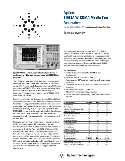
AgilentE1963A W-CDMA Mobile Test ApplicationFor the E5515C (8960) Wireless Communications Test Set Technical OverviewSpeed UMTS test plan development and get your devices to market sooner, while ensuring compliance with TS34.121 test standards.The E1963A W-CDMA Mobile Test Application, when used with the Agilent GSM, GPRS, and EGPRS applications, is the industry standard for Universal Mobile Telecommunications (UMTS) mobile test. Agilent’s 8960 (E5515C) test set provides you with a single hardware platform that covers all the UMTS/3GPP (Third Generation Partnership Project) radio formats: W-CDMA, HSPA, GSM, GPRS, and EGPRS.Exceed your calibration test time goals with the E1999A-202 fast device tune measurement. Simultaneously calibrate your device’s transmitter (Tx) output power and receiver (Rx) input level across level and frequency. E1999A-202 is a superset of the discontinued E1999A-201. It not only offers the equivalent capabilities of theE1999A-201, but is also further enhanced to reduce the calibration test times for W-CDMA, cdma2000®, and 1xEV-DO wireless devices with smaller step size support (10 ms step size versus 20 ms step size).Reach your high-volume production goals by moving prototypes quickly into production with this test solution’s fast and repeatable measurements, accurate characterization, and ease of programming. The HSPA, W-CDMA, GSM, GPRS, and EGPRS product combination delivers a complete and integrated UMTS test solution in a single box. FM radio source, a single channel GPS source (E1999A-206) and PESQ measurement (E1999A-301) are also added into the test box for FM radio receiver calibration, GPS receiver calibration and audio quality test without the need of an external audio analyzer. This fast, one-box approach simplifies your production process and increases your production line effectiveness. With the most complete test functionality for 3GPP TS34.121 Section 5 and 6 tests, E1963A Options 403,405 and 413 provide fast, flexible measurements and options in user equipment (UE) connectivity, giving design and manufacturing test engineers more flexibility in creating test plans and the assurance that designs meet technology standards. The option 423 supports 64QAM downlink modulation and RB test mode connection.Key Capabilities•Fast device calibration across level and frequency simultaneously•Test HSPA devices as defined in 3GPP TS34.121•Switch between HSPA sub-test conditions while on an active connection•Test all UMTS technologies with one connection maintained throughout•Test all frequency bands I through XIV•FM and GPS receiver calibration in one box•Test vocoder speech quality using the industry standard PESQ algorithmTx measurements W-CDMA HSDPA HSUPA Thermal power Yes Yes Yes Channel power Yes Yes Yes Adjacent channel leakage ratio Yes Yes Yes Waveform quality Yes Yes Yes Spectrum emission mask Yes Yes Yes Phase discontinuity Yes Yes Yes Inner loop power Yes Occupied bandwidth Yes Yes Yes Code domain power Yes Yes YesIQ constellation Yes Yes- YesTx on/off power Yes Yes Yes Frequency stability Yes Yes Yes Dynamic power analysis Yes Yes YesTx dynamic power YesSpectrum monitor Yes Yes YesRx measurements W-CDMA HSDPA HSUPA Loopback BER Yes N/A N/A BLER on DPCH (W-CDMA)Yes N/A N/A HBLER on HS-DPCCH (HSDPA)N/A YesN/A3GPP TS 34.121 Adherence3GPP TS34.121 Testdescription E1963A5.2 Maximum output power Yes(Release 5 only)5 5.2AA Maximum output power with HS-DPCCH(Release 6 and later)Yes55.2B Maximum output power with HS-DPCCH and E-DCHYes5 5.2C UE-relative code-domain power accuracy Yes5DPCCH and E-DCH55.3 Frequencyerror Yes5.4.1 Open loop power control Yes5.4.2 Inner loop power control Yes5.4.3 Minimum output power Yes5.4.4 Out-of-sync handling of output power E6703X2 5.5.1 Transmit off power Yes5.5.2 Transmit on/off time mask Yes5.6 Change of TFC E6703X5.7 Power setting in UL compressed mode5.7A HS-DPCCH Yes55.8 Occupied bandwidth (OBW)Yes5.9 Spectrum emission mask (SEM) Yes5.9A Spectrum emission mask with HS-DPCCH Yes5 5.9B Spectrum emission mask with E-DCH Yes5 5.10 Adjacent channel leakage power ratio (ACLR) Yes5.10A ACLR with HS-DPCCH Yes5 5.10B ACLR with E-DCH Yes5 5.11 Spuriousemissions Yes2 5.12 Transmitintermodulation Yes3 5.13.1 Error vector magnitude (EVM) Yes5.13.1A Error vector magnitude (EVM) with HS-DPCCH Yes5 5.13.1AA EVM and phase discontinuity with HS-DPCCH Yes5 5.13.2 Peak code domain error Yes5.13.2A Relative code domain error with HS-DPCCH Yes5.13.2B Relative code domain error with HS-DPCCH andE-DCHYes5.13.3 Phase discontinuity measurement Yes3GPP TS34.121 Testdescription E1963A/ E6703X6.2 Referencesensitivity Yes6.3 Maximum input level Yes 6.3A Maximum input level for HS-DPCCH reception(16QAM)Yes56.4 Adjacent channel selectivity (ACS)(Release 99 and Release 4)Yes1 6.4A ACS (Release 5 and later releases) Yes16.5 Blockingcharacteristics Yes16.6 Spuriousresponse Yes16.7 Intermodulationcharacteristics Yes16.8 Spuriousemissions Yes21 Requires use of external source2 Requires use of external spectrum analyzer3 Requires use of external spectrum analyzer and source4 Internal fading is possible using Baseband Studio. Most of these tests require external instrumentation such as faders. Consult TS34.121 for details.5 Requires Feature option license 3GPP TS34.121Test description E1963A7.2Demod in static propagation Yes7.3Demod in multi-path E6703X47.4Demod in moving channel E6703X47.5Demod in birth-death E6703X4What to Order for W-CDMA/HSPAModel number DescriptionE5515C8960 Series 10 Wireless Communications Test SetE5515C-003Flexible CDMA base station emulatorE1963A W-CDMA mobile test applicationE1963A-403HSDPA test modesE1963A-405E1963A-413HSDPA 14.4Mbps TMHSUPA test modesE1963A-423HSPA+ test modesWhat to Order for UMTSModel number DescriptionE5515C8960 Series 10 Wireless Communications Test SetE5515C-002Second RF sourceE5515C-003Flexible CDMA base station emulatorE1963A W-CDMA mobile test applicationE1963A-403HSDPA test modesE1963A-405HSDPA 14.4Mbps test modeE1963A-413HSUPA test modesE1963A-423HSPA+ test modesE1968A-202GSM/GPRS/EGPRS mobile test applicationE1987A Fast switching test applicationFeature Options List for W-CDMA/HSPA Model number DescriptionE1963A-401End-to-end videoE1963A-402Video loopbackE1963A-403HSDPA test modesE1963A-405HSDPA 14.4Mbps test modeE1963A-408Enhanced Audio (real-time vocoder, WB-AMR, DAI) E1963A-409Adv. SMSE1963A-413HSUPA test modesE1963A-423E1999A-202E1999A-206E1999A-301HSPA+ test modesEnhanced fast device tune measurementSingle channel GPS sourcePESQ MeasurementRelated LiteratureE1963A W-CDMA Test Application, photocard, 5989-3414ENAgilent 8960 Wireless Communications Test Set HSPA Applications, photocard, 5989-7515EN8960 Series 10 Wireless Communications Test Set, configuration guide, 5968-7873EFor More InformationLearn more about the E1963A test application and HSPA Options at:/find/E1963AFor details on the manufacturing test solutions visit:/find/8960mfg Technical SpecificationsThese specifications apply to an E5515C mainframe with Option 003 (or E5515B/T upgraded to equivalent configuration) when used with the latest E1963A test application or the E1987A test application.Specifications describe the test set’s warranted performance and are valid for the unit’s operation within the stated environmental ranges unless otherwise noted. All specifications are valid after a 30-minute warm-up period of continuous operation.Supplemental characteristics are intended to provide typical, but non-warranted, performance parameters that may be useful in applying the instrument. These characteristics are shown in italics and labeled as “typical” or “supplemental.” All units shipped from the factory meet these typical numbers at +25 °C ambient temperature without including measurement uncertainty. What Included in This Technical OverviewThis data sheet is organized in four sections:•HSPA Specifications•W-CDMA Specifications•HSPA and W-CDMA Common Technical Specifications •General SpecificationsHSPA/HSPA+ Specifications(E1963A Option 403, 405, 413 and 423)Call connection typesHSPA FDD test modeHSPA FDD test modes are supported by the E1963A. FDD test mode provides Layer 1 functionality only. No higher-level signaling is provided or accepted. No higher-level call processing operations are performed. The test set assumes that the user has appropriately configured the UE.FDD test mode allows you to test the parametric performance of your UE’s transmitter and receiver without call processing. In FDD test mode, the test set does not send any signaling information on the downlink. Rather, it continuously generates a downlink signal and searches for a corresponding uplink signal. The UE must synchronize to the downlink signal and send an appropriate uplink signal, which the test set uses to measure the UE’s transmitter and receiver performance. Any changes to the UE configuration must be accomplished by directly sending commands to the UE from a system controller through a proprietary digital interface./rfcomms/refdocs/wcdma/ wcdma_gen_bse_fddtest.phpFRC H-Set supportH-Set Modulation Nominal avg. inf. Bit rate (Mbps)2 QPSK, 16QAM 0.801, 1.1663 QPSK, 16QAM 1.601, 2.3324 QPSK 0.5345 QPSK 0.8016 QPSK, 16QAM 3.219, 5.6898 64QAM 13.25210 QPSK, 16QAM 4.68, 8.774HSPA RB test modeRB test mode uses signaling to establish a test control connection between the test set and UE, allowing you to test the parametric performance of your UE’s transmitter and receiver. In RB test mode, the test set provides signaling to establish a connection between the UE and the test set. The test set can also signal the UE to change its configuration and alter the uplink signal. The test set measures the uplink signal to determine the UE’s transmitter and receiver performance. RB test mode is operated on the downlink, simultaneously supporting a symmetrical RMC (Reference Measurement Channel) of 12.2 kbps. This symmetrical RMC is typically used for transmitter testing and receiver testing using BER./rfcomms/refdocs/wcdma/ wcdma_gen_bse_hsdpa_rbtest_setup.php HSPA handoversTo support the HSPA tests and sub-test conditions specified in the 3GPP standards, the Transport Channel Reconfiguration procedure allows you to change HSPA parameters while on a live connection. βc, βd, ∆ACK,∆NACK, ∆CQI, CQI feedback cycle (k), CQI repetition factor, Ack-Nack repetition factor, and default DPCH offset (DOFF) parameters can all be modified without dropping the HSPA connection. In addition, when using the user-defined DL configuration for HSDPA in RB test mode, the number of HARQ processes and UE IR buffer size can be changed on a live HSDPA connection to provide flexibility in testing multiple configurationsThe Radio Bearer Reconfiguration allows you to handover from a CS Domain or CS/PS Domain HSDPA RB Test Mode connection or HSPA RB Test Mode connection to a (non-HSDPA/non-HSPA) symmetrical RMC. The Radio Bearer Reconfiguration also allows you to change many other network parameters as part of the reconfiguration.You can also hand over between channels within a band and between bands using the Physical Channel Reconfiguration procedure. This allows you to test channels in the low, middle, and high frequency portions of each UE-supported band without dropping the HSPA connection./rfcomms/refdocs/wcdma/ wcdma_gen_call_handoffs.phpInter-system handoversAlmost all UEs support multiple formats today. To speed the process of testing multiple formats with call processing, you can perform handovers from HSPA to GSM and from HSPA to W-CDMA. If your test plan requires testing HSPA followed by GSM, GPRS, and/or EGPRS, you can hand over from an HSPA FRC to GSM test mode using the system handover. If your test plan requires testing W-CDMA as well, you can hand over from an HSPA FRC to a W-CDMA RMC, then use the existing W-CDMA RMC to GSM test mode system handover to test GSM, GPRS, and/or EGPRS./rfcomms/refdocs/wcdma/ wcdma_gen_call_handoffs.phpHSDPA user-defined downlinkVerify your device’s HSDPA throughput at the MAC-hs level with the user-defined downlink (DL) in the E1963A Option 403 and 405. Flexibly configure the 8960 to provide up to a 14.4 Mbps Radio Bearer (RB) test mode signal for testing HS-DSCH category 9 and 10 devices by setting the number of active HS-PDSCHs, transport block size index, modulation type, inter-TTI, number of HARQ processes, and UE incremental redundancy (IR) buffer size. HSPA+ option supports DL 64QAM and throughput is up to 21 Mbps./rfcomms/refdocs/wcdma/ wcdma_gen_bse_hsdpa_rbtest_setup.phpHSPA RF generatorW-CDMA channels active in HSPA modeW-CDMA(spread factor) Default assignmentAlternate choicesP-CCPCH (256) 1 --PICH (256) 16channel code settable within available coderangeDPCH, 12.2 kpbs RMC(128)20 HSDPA within available coderangeHS-SCCH-2 (128) 6 HS-SCCH-3 (128) 9 HS-SCCH-4 (128) 10 HS-PDSCH (16) 7OCNS HSDPA (128)122, 123, 124, 125, 126, 127HSUPA within available coderangeE-HICH (128) 22 E-RGCH (128) 22Common pilot channel relative level: -20 to 0 dBPrimary CCPCH relative level: -20 to 0 dB PICH relative level: -20 to 0 dBDPCH relative level : settable from -30 to 0 dB with 0.01 dB resolutionHS-SCCH relative level of individual code channels:HS-SCCH channel can be off but at least one channel is in presence. For 64QAM downlink, at least two channels are in presence. the channel level is settable from -20 to 0 dB HS-PDSCH relative level of all active code channels: settable from -20 to 0 dBPrimary sync channel relative level: always the same as P-CCPCHDownlink CDMA modulationModulation type: QPSK,16QAM and 64 QAM per 3GPP standard QPSK residual EVM : < 10%, typically < 3%QPSK carrier feed through: < -25 dBc , typically < -35 dBc nominal ambient performance: < -45 dBc 16QAM residual EVM: typically < 3%16QAM carrier feed through: typically < -35 dBc nominal ambient performance: < -45 dBcOCNS – orthogonal channel noise sourceComposed of 6 channels per Table E.5.5 in Annex E of 3GPP 34.121. OCNS channel can be off but at least 1 OCNS channel is in presence.OCNS channel relative level range: automatically calculated from other code channel relative levels to provide thecomposite W-CDMA cell power, but user-allocated channel level available./rfcomms/refdocs/wcdma/wcdma_gen_bse_gen_info.php#BCGCBAHEHSPA RF analyzer (measurements only) Real-time demodulation of: uplink– DPCH, HS-DPCCH, E-DCHTx measurementsChannel power measurementMeasurement bandwidthRRC filter off: measured with a bandwidth greater than (1 + α) * chip rate, where α = 0.22 and chip rate = 3.84 McpsRRC filter on:measured with a filter that has a root-raised cosine(RRC) filter response with roll-off α = 0.22 and a bandwidth equal to the chip rate 3.84 MHz BW centered on the active uplink channel)Measurement range:-61 to +28 dBm/3.84 MHzMeasurement interval: settable from 0.01 to 12 msMeasurement accuracy (at + 10 °C from the calibration temperature):< ±1.0 dB (typically < ±0.5 dB) for measurement intervals of 333 µs to12 ms over 698 to1024 MHz, 1400 to 1500 MHz and 1700 to 2000MHz< ±1.0 dB (typically < ±0.55 dB) for measurement intervals of 333 µs to12 ms over 2480 to 2580 MHz,< ±1.0 dB (typically < ±0.6 dB) for measurement intervals of 67 to < 333 µs over 698 to1024 MHz, 1400 to 1500 MHz and 1700 to 2000 MHz Measurement triggers: auto, immediate, protocol, RF rise, external, and HS-DPCCH/rfcomms/refdocs/wcdma/ wcdma_meas_chanpow_desc.php Phase discontinuityMeasurement method: the measured results include the phase discontinuity (defined as the phase difference of adjacent timeslots) as well as all waveform quality results for each timeslotInput power level range:Phase discontinuity: -61 to +28 dBm/3.84 MHzOther measurements: -25 to +28 dBm/3.84 MHzInput frequency ranges: 800 to 1000 MHz, 1700 to 1990 MHz Phase discontinuity range: ±180 degreesEVM range: 0 to 35% rmsPhase discontinuity measurement accuracy:< ±2.4 degrees (typically < ±1.7 degrees) for input levels of -25 to +28 dBm/3.84 MHz< ±2.6 degrees (typically < ±1.9 degrees) for input levels of -51 to < -25 dBm/3.84 MHzOther reported parameters with phase discontinuity: all measurements found in the waveform quality measurement are also available; the specifications are the same in both measurements, including the input power range of the waveform quality measurement Measurement interval: 617 µs (= 1 timeslot (667 µs) – 25 µs transient periods at either side of the nominal timeslot boundaries) or 283 µs (0.5 timeslot (333 µs) – 25 µs transient periods at either side of the nominal timeslot boundaries)Measurement triggers: protocol, external, and HS-DPCCH Temperature range: +20 to +55 °CConcurrency capabilities: phase discontinuity measurements cannot be made concurrently with other measurements/rfcomms/refdocs/wcdma/ wcdma_meas_wpdiscon_desc.phpWaveform quality measurement (HSDPA)Waveform quality measurement: composite EVMMeasurement format:HPSKMeasurement chip rate: 3.84 McpsInput level range: -25 to +28 dBm/3.84 MHzMeasurement range: < 35% EVMMeasurement interval: 0.5 to 1.0 timeslot with choice to include orexclude 25 µs transient periodsEVM measurement accuracy (including the effects of residualEVM):EVM measurement accuracy:< 2.8% rms, typically < 2.4% rms for UE EVM > 1% rms, < 2200 MHz< 3.2% rms, typically < 2.8% rms, for UE EVM > 1% rms, 2300 to 2580MHzMeasurement triggers: auto, protocol, immediate, external, and HS-DPCCHHS-DPCCH trigger alignment:adjustable oversubframes 0 to 5timeslots Ack Nack or CQIsubslots 0 to 0.5 timeslotOther reported parameters with EVM:•frequency error•magnitude error•phase error•origin offset•timing error•peak code domain errorFrequency error measurement range: ±1 kHzResidual frequency error:< ± (5 Hz + timebase accuracy) for a measurement interval of 1timeslot< ±(7 Hz + timebase accuracy) for a measurement interval of 0.5timeslotFrequency error measurement accuracy:Peak code domain error accuracy:< ±0.4 dB for code power levels > -25 dBTiming error measurement range: ±10 µsTiming error measurement accuracy: < ±0.5 chips (±130 ns)/rfcomms/refdocs/wcdma/wcdma_meas_wfrmqual_desc.php#CIHBBHDJIQ tuningAll measurements found in the waveform quality measurementare also available in the IQ tuning measurement; thespecifications are the same in both measurements./rfcomms/refdocs/wcdma/wcdma_meas_iqtuning_desc.phpHSPA Code domain powerCode domain power accuracy:< ±0.4 dB for code power level > -25 dBRelative code domain error (RCDE) accuracy:< ±0.5 dB for RCDE level > -20 dBRelative code domain power accuracy (RCDPA):< ±0.2 dB for code power level from ≥ -10 to 0 dB< ±0.3 dB for code power level from ≥ -15, -10 dB< ±0.4 dB for code power level from ≥ -20, -15 dBAll measurements found in the waveform quality measurement are also available in the code domain measurement; the specifications are the same in both measurements.Measurement triggers: immediate, protocol, external, auto, HS-DPCCH and Even Frame/rfcomms/refdocs/wcdma/ wcdma_meas_cod_dom_desc.phpAdjacent channel leakage ratio (ACLR) Measurement method:ratio of the filtered mean transmitted power to the filtered mean power in an adjacent channel; both the transmitted and the adjacent channel powers are measured with a filter that has a RRC response with roll-off α = 0.22 and a bandwidth equal to the chip rateInput power level range: +5 to +28 dBm/3.84 MHzInput frequency ranges: 698 to 1000 MHz, 1400 to 1500 MHz, 1700 to 2000 MHz, and 2480 to 2580 MHz,Measurement level ranging: autoMeasurement accuracy: < +0.8 dB (typically < +0.5 dB), including the effects of the residual floor, for measurements at -33 dBc at +5 MHz offsets and -43 dBc at +10 MHz offsets, and +10 °C from the calibration temperatureResidual ACLR floor: < -48 dBc for +5 MHz offsets, < -58 dBc for +10 MHz offsetsMeasurement triggers: auto, protocol, immediate, external, HS-DPCCH Trigger alignment: adjustable over subframes 0 to 5 Measurement interval: 1 timeslotMeasurement result: dBc relative to in-channel transmitted power /rfcomms/refdocs/wcdma/ wcdma_meas_aclr_desc.php Dynamic power analysisMeasurement method: graphical display of the uplink power waveform including HS-DPCCH, DPCH versus time; by using the HS-DPCCH trigger source, results will be aligned to the HS-DPCCHInput power level range: -61 to +28 dBm/3.84 MHz Measurement level ranging: autoData capture range: combination of number of steps and step length cannot exceed 58.26 msMeasurement bandwidth: selectable RRC filter on or offMeasurement interval: settable from 0.01 to 12 ms (must be less than or equal to the step length)Measurement accuracy: (at +10 °C from calibration temperature with measurement interval 333 µs to 12 ms):Input level range Measurement accuracy Frequency range < 25 dBtypically < ±0.5 dB 1700 to 2000 MHz< ±1.0 dB,typically < ±0.55 dB 2480 to 2580 MHz < 35 dBtypically < ±0.55 dB 1700 to 2000 MHz< ±1.0 dB,typically < ±0.6 dB 2480 to 2580 MHz< 40 dB typically < ±0.55 dB1700 to 2000 MHz< ±1.0 dB,typically < ±0.7 dB2480 to 2580 MHz Measurement triggers: RF rise, external, and HS-DPCCHHS-DPCCH trigger alignment:adjustable over subframes 0 to 5 /rfcomms/refdocs/wcdma/ wcdma_meas_wdpanalysis_desc.phpSpectrum emission mask (SEM)Measurement method: ratio of the transmitted power (3.84 MHz BW RRC) to offset frequencies, which are between 2.5 MHz and 12.5 MHz away from the UE center carrier frequency; the offset frequencies are measured in 30 kHz or 1 MHz bandwidths, depending on the offsetInput power level range:+5 to +28 dBm/3.84 MHzInput frequency ranges: 698 to 1000 MHz, 1400 to 1500 MHz, 1700 to 2000 MHz, and 2480 to 2580 MHzMeasurement accuracy:< +1.5 dB (typically < +0.8 dB) for the following offsets (+10 °C from the calibration temperature)8.5 to 12.5 MHz -49 1 MHz Measurement accuracy for additional spectrum emission limits for bands II, IV, V, X, XII, XIII and XIV:typically < +1.1 dB for the following offsets (+10 °C from the calibration temperature) Frequency offset Levels (dBm) Meas BW2.5 to3.5 MHz --15 dBm 30 kHz3.5 to 12.5 MHz -13 dBm or -15 dBm 1 MHz or 100 kHzMeasurement triggers:auto, protocol, immediate, external, and HS-DPCCHHS-DPCCH trigger alignment:adjustable over subframes 0 to 5 /rfcomms/refdocs/wcdma/ wcdma_meas_spec_em_mask_desc.php Rx measurementsHSDPA/HSPA+ block error ratioMeasurement method: test set counts the ACK/NACK/statDTX on UE HS-DPCCH and uses the results to calculate BLERBLER measurement input level range: -50 to +28 dBm/3.84 MHzReported parameters: measured BLER, number of blocks tested, throughput, number of ACKs, number of NACKs, number of stat DTXs, and median CQIConcurrency capability: HSDPA BLER measurements cannot be made concurrently with phase discontinuity, PRACH Tx on/off, or inner loop power measurements, or while speech is provided on the downlink; HSDPA BLER measurements can be made concurrently with all other measurements, including W-CDMA loopback BER and BLER/rfcomms/refdocs/wcdma/ wcdma_meas_hblerror_desc.phpHSDPA bit error ratioMeasurement method: the 8960 can be configured so that BER can be measured externally using the 8960 downlink and external UE monitoring softwareW-CDMA SpecificationsCall connection typesEnd-to-end video conferencing (Option 401)Loop back video conferencing (Option 402)Imaging testing real-time mobile video conferencing at your own desk!The E1963A, when configured as a two-instrument system, provides true H324 call setup with live video and audio from both mobile devices.With only one E5515C, Loop back video call can be setup with option 402.Validate compatibility by testing interoperability between your mobile and the competitor models offered for the same network.•complete call setup, mobile origination, and mobile release•64k circuit-switched UDI channel•H324 call setup/rfcomms/refdocs/wcdma/ wcdma_gen_call_video_call.phpAMR voiceStandard voice call with audio loopback for a quick check of voice functionality for 12.2 k rate; also many more AMR rates, such as 4.75, 5.15, 5.9, 6.7, 7.4, 7.95, 10.2, and 12.2 k•UE and BS origination 12.2 k•UE and BS release/rfcomms/refdocs/wcdma/ wcdma_gen_bse_amrvoice.phpFDD test modeFDD test mode allows you to test the parametric performance of your UE’s transmitter and receiver without call processing. In FDD test mode, the test set does not send signaling information on the downlink. Rather, it continuously generates a downlink signal and searches for a corresponding uplink signal. The UE must synchronize to the downlink signal and send and appropriate uplink signal, which the test set uses to measure the UE’s transmitter and receiver performance. Any changes to the UE configuration must be accomplished by directly sending commands to the UE from a system controller through a proprietary digital interface./rfcomms/refdocs/wcdma/ wcdma_gen_bse_fddtest.php RB test modeFast conformance test calls with significant configuration control and testing capabilities•BS origination and release•Symmetrical configuration: W-CDMA modes support symmetrical RMCs at 12.2, 64, 144 and 384 k rates.These symmetrical RMCs are typically used fortransmitter testing and receiver testing user BER (vialoopback type 1) or BLER (via loopback type 2) •Asymmetric configuration: the asymmetrical RMCs use either a 12.2 k channel or a 64 k channel on theuplink. The primary purpose of the symmetrical RMCsis to provide a way to make a BLER measurement bycounting retransmission requests that the UE sends.There is no need for data loopback in this mode /rfcomms/refdocs/wcdma/ wcdma_gen_bse_rbtest_setup.phpInter-system handoverDual-mode functionality is required for most W-CDMA phones, as GSM is an integral part in the majority of devices shipping today. Inter-system handovers provide a means to validate dual-mode performance at your desk instead of roaming on a real network. When operated in conjunction with compressed mode, this feature can very closely emulate the basics of a real handover as made on the network.•blind handovers from W-CDMA to GSM•configurable landing GSM cell•test control to GSM voice•W-CDMA AMR voice to GSM voice/rfcomms/refdocs/wcdma/ wcdma_gen_call_handoffs.php。

汉普LTE类产品测试方法指导版本:V1.0共53 页(包括封面)目录1.1 CMW500初始配置设置 (3)1.2最大发射功率测试 (9)1.3最大功率衰减(MPR) (11)1.3附加最大功率衰减(A-MPR) (13)1.3配置UE功率测试 (15)1.4矢量幅度误差EVM(PUSCH) (18)1.5频率误差 (20)1.6占用带宽 (20)1.7 ACLR临道泄露比 (21)1.8绝对功率控制容限 (25)1.9相对功率控制容限 (29)1.10带内发射(InBandEmissions) (34)1.11 IQ Const (35)1.10 EVM vs C(subcarrier) (38)1.11 Spectrum Flatness (39)1.12 Spectrum Emission Mask (41)2.1 LTE Ext.BLER (42)2.2最大输入电平 (45)附录: (47)A.LTE对应频段 (47)B.EVM的计算 (50)C.频谱发射模板的通过判定 (50)D.最大功率衰减的测试目的 (50)E.LTE综测软件使用介绍 (51)F.LTE校准校准环境的搭建 (53)1.1 CMW500初始配置设置针对CMW500的初始化操作进行介绍,主要进行信令下的测试。
初始化设置(1)点击CMW500左上角RESET键,弹出复位界面(2)选择Global菜单下的Reset选项,然后点击Reset按钮确认(3)设置线损,在LTE Signaling界面下点击Config按钮,在RF Settings下选择测试端口以及线损,设置为1.00dB(4)设置功率控制模式,在LTE Signaling界面下点击Config按钮,在Uplink PowerControl下选择TX Power Control(TPC),Active TPC Setup选择为Max power模式。
(6)网络连接设置,在LTE Signaling界面下点击Config按钮,在Connection下选择Additional Spectrum Emission设置为NS_01模式。

8960!C M U200!全中文说明书_手机综测仪基本操作和设置-CAL-FENGHAI-(2020YEAR-YICAI)_JINGBIAN一、8960综测仪基本操作和设置:1、三个关键按钮:Measurement, Call setup, System config2、按下System config 系统配置按钮进入仪器参数设置界面a、点击Instrument Setup 设置正确的GPIB地址b、点击RF IN/OUT Amptd offset按钮设置相应的线损Passloss值(我司一般880-960 GSM , 1710-1880 DCS ;在进行耦合测试时,GSM 22, DCS 28)c、点击Application selection 按钮后,界面有两个按钮 Application Switch切换测试应用软件GSM / GPRS ,Application Setup 选择测试应用版本(一般情况下不用考虑此项)d、 RF IN / OUT (Output port 设置选择IN/OUT)3、 Call Setup 界面操作a、 Operating Mode 操作模式设置:一般选择Active Cell ,在进行META匹配调试时,CMU或8960都要设置为Non-Signalling,所谓非信令模式就是选择含有广播信道BCH的操作模式,仪器8960仅进行通讯;Signalling模式有CellGPRS\Cell EGPRS,仪器8960起基站的作用。
b、 Connection Type 连接类型设置:一般选择Auto模式,也可选择ETSI Type A,在测误码率BER 时要选择 BLER模式。
c、 BCH Parameters参数设置,Cell power 一般开始设置要大一些,譬如-65dbm,以便能够顺利建立通信,然后可以调节到需要的值;Cell Band 要和所测试的信道一致EGSM/DCS或者PGSM;d、 TCH Parms 参数设置:Traffic Band 选择PGSM/DCS;Traffic Channel Traffic一般测试几个典型信道1、37、69、124、512、698、885、975、1023或者特定的信道;MS TX Level 一般都选择最大功率级0/5. Channel mode 业务信道模式(编码器)选择一般不用理会;timeslot和Time advance 、mobile loopback也不太考虑;Speech 选择Echo回音模式。

DSP 专有名词解释AAbsolute Lister 绝对列表器ACC 累加器AD 模拟器件公司Analog DevicesADC 数模转换器All-pipeline-Branching 全流水分支ALU 算数逻辑运算单元Arithmetic Logical UnitAMBA 先进微控制器总线结构(ARM处理器的片上总线)Advanced microcontroller bus architectur eANSI 美国国家标准局AP 应用处理器Application ProcessorAPI 应用程序编程接口Application Programmable interface ARAU 辅助寄存器单元Auxiliary Register Arithmetic Unit ARP 辅助寄存器指针/地址解析协议Address Resolution ProtocolArchiver Utility 归档器公用程序ASIC 专用集成电路Application Specific Integrated Circ uitASP 音频接口/动态服务器页面(Active Server Page)ASK 振幅调制BB0,B1 DARAM B0、B1 块双口随机存储器BDM 背景调试模式Background Debug Mode Bluetooth 蓝牙BEGIER 调试中断使能寄存器BOPS 每秒十亿次操作BOOT Loader 引导装载程序CC Compiler C编译器CALU 中央算术逻辑单元Central Arithmetic Logical UnitCAN 控制器局域网Controller Area NetworkCCS 代码调试器/代码设计套件Code Composer StudioCDMA 码分多址Code Division Multiple AccessCode Size 代码长度CLKX 发送时钟引脚CLKR 接收时钟引脚COFF 通用目标文件格式Common Object File FormatConvolution 卷积Cost Efficient 成本效益Cost Revenue Analysis 成本收入分析Cross Reference List 交叉引用列表器CSM 代码安全模块Code Security ModuleDDAG 地址发生器Data Address Generator DAR 数据存储页面指针DARAM 双口随机存储器Double Access Random Access MemoryDMSoC 达芬奇数字媒体片上系统DP (DPH:DPL) 数据页面指针寄存器Data -page PointerDR 数据接收引脚DRR 数据接收寄存器Data receive registerDRAB 数据读地址总线Data Read Address BusDRDB 数据读数据总线Data Read Data BusDRR 数据接收寄存器Data receive registerDSC 数字信号控制器Digital Signal ControllerDSK DSP初学者套件DSP Starter KitDSP 数字信号处理/ 数字信号处理器Digital Signal Processing/ProcessorDSP/BIOS 小型嵌入式实时的操作系统DX 数据发送引脚DWAB 数据读地址总线Data Write Address Bus DWDB 数据写数据总线Data Write Data BusEeCAN 增强型控制器局域网(增强型CAN总线)Enhanced Controller Area NetworkEV 事件管理器Event ManagerEvent driven 事件驱动EVM 评估模块Evaluation Module EDMA 增强的直接存储器访问EMCV 嵌入式计算机视觉库Embedded Computer Vision LibraryEMIF 外部存储器接口External Memory InterfaceEmulator 硬件仿真器————Simulator 软件仿真器EOS 嵌入式操作系统Embedded Operation System ES 嵌入式系统Embedded SystemETM 嵌入式跟踪宏单元Embedded Trace MacrocellF—HFFT 快速傅里叶变换fast fourier transformFFS 闪存系统文件Flash file systemFinite Impulse Response Filter 有限长脉冲响应滤波器FPWR flash的功耗模式寄存器Flash Power Word Register FSM 有限状态机Finite State Machine FSR 接收帧同步引脚FSX 发送帧同步引脚GAL 普通阵列逻辑Generic array logicGPIO 通用输入输出接口General Purpose Input Output Port GPT 通用定时器General purpose timerGPRS 通用分组无线业务General Packet Radio ServiceGUI 图形用户界面Graphical User InterfaceHCD USB主机控制器驱动程序HostController DriverHWI 硬件中断Hardware Interrupt HPI 主机接口Host Port InterfaceIIBQ 指令缓冲队列Instruction Buffer QueueIC 集成电路Integrated CircuitICE 实时在线仿真In-Circuit EmulatorIDE 集成开发环境Integrated Development EnvironmentIDMA 内部直接存储器访问I^2C 内部集成电路Inter Integrated Circuit Integrated Preprocessor 集成预处理器Interrupt Redirect 中断重定向IPC 进程间通信Inter Process Communication IRDA 红外线数据协会Infrared Data AssociationISP 在线编程In-System programmable ISR 中断服务程序Interrupt service routineISS 指令集模拟器Instruction set simulatorJ—LJTAG 边界扫描接口/联合测试行动小组Joint Test Action GroupLCD 液晶显示器Liquid Crystal Display Library Build Utility 创建库工具Lowest power/MIPS 最低功耗LPM 低功耗模式Low Power ModuleM—NMAC 媒体访问控制Media Access ControlMBPS 每秒百万比特Million Bits Per Second MCU 单片机Micro Control Unit McASP 多通道音频串口Multichannel audio serial portMcBSP 多通道缓冲接口Multichannel Buffered Serial Port MFLOPS 每秒百万次浮点操作MIPS 每秒百万条指令Million Instructions Per Second MMC 多媒体卡Multimedia Card MMR 内存映射式寄存器Memory Map RegisterMMU 存储管理单元Memory Management Unit MOPS 每秒百万条操作Million Operation Per Second MPU 嵌入式处理器/微处理器Micro Processor UnitMSI 中规模集成电路medium-scale integrationMSP 混合信号处理器Mixed Signal ProcessorNFC 近场通信Near Field CommunicationNTSC 国家电视标准委员会National Television Standard CommitteeNull-overhead 零开销OOCD 片上调试技术On-chip debugging techniquesOEM 原始设备生产商(代工生产)Original equipment manufacturer OFDM 正交频分多路复用技术Orthogonal Frequency Division MultiplexingOLE 对象连接与嵌入Object linking and embeddingOMAP 开放式多媒体应用平台Opening Multimedia Application PlatformOpenCv 开放计算机视觉库Open computer vision libraryOSD 屏幕显示On Screen DisplayOSC 晶体整荡器OTP 一次性可编程One Time ProgrammablePP(PH:PL)乘积结果寄存器PAB 程序地址总线Program Address BusPAL 可编程阵列逻辑programmable array logicPAL 逐行倒相Phase Alteration Line PAN 个人局域网personal area networkPC 程序计数器Program CounterPIE 外设中断扩展Peripheral Interrupt Expansion PIN 个人身份识别号Personal Identification Number PLD 可编程逻辑器件Programable Logic DevicePLL 锁相环Phase Locking LoopPMC 程序存储控制器Program Memory ControllerPointer Arithmetic 定点运算PPM 脉冲相位调制Pulse Position ModulationPRDB 程序读数据总线Program Read Data BusPreemptive kernel 抢占式内核PREG 乘积存储器Process Manager 进程管理器Product Shifter 乘积移位器PWM 脉宽调制Pulse Width Modulation RRBR 接收缓冲寄存器Receive buffer registerRF 无线电射频Radio FrequencyResource Manager and Process Manager 资源和进程管理器RISC 精简指令集Reduced Instruction Set ComputingROM 只读存储器Read Only MemoryRSR 接收移位寄存器Receive Shift RegisterRTC 实时时钟Real Time Clock Run Time Support Library 运行支持库Run Time Support Library DSP Algorithm Standard 运行支持库DSP 运算法则标准SSARAM 单口随机存储器Single Access Random Access MemorySBSRAM 同步突发静态RAM Scan_Based Emulator 基于扫描的硬件仿真器SCI 串行通信接口Serial Communication Interface SCR 交换中心资源Switched Central Resource SD 安全数字卡Secure Memory Card SDRAM 同步动态RAMShell Program 外壳程序Simulator 软件仿真器SIR 异步半双工的红外通信方式Serial InfraredSOC 片上系统System On ChipSource Inter_List Feature 源代码交叠工具SPI 串行外设接口Serial Peripheral Interface Super Harvard 超级哈佛结构SWI 软件中断Software Interrupt SWWSR 软件等待状态寄存器Wait for a status register software (供参考)System Crash 系统崩溃TTAP 测试访问口Test Access PortTEC 错误传输计数器Transmission error counterTFT 薄膜场效应晶体管Thin Film TransistorTI 德州仪器Texas InstrumentsTREG 临时寄存器TSIP 电信串行接口端口Telecommunication Serial Interface PortU-XUART 通用异步收发器Universal Asynchronous receiver Transmitter UWB 超宽带通信Ultra wideband communicationsVLIW 超长指令字Very Long Instruction Word VPBE 视频处理后端Video Processing Back End VPFE 视频处理前端Video Processing Front End VPSS 视频处理子系统Video Processing Sub SystemWDT 看门狗定时器Watchdog TimerWi-fi 一种无线方式互连技术Wireless fidelityXDS 扩展开发系统External Development SystemXARn(ARnH:ARn)(n取0—7)辅助寄存器XINTF 存储器外部扩展接口External interfaceXSR 发送移位寄存器XT(T:TL)乘法单元被乘数寄存器/暂存器数字12 - stage Pipeline 十二级流水线3CComputer Communication Consumer3G 第3代移动通信技术The 3rd Generation Telecommunication40-bit barrel shifter 40位桶形移位器。