ESP8266WIFI模块使用说明
- 格式:docx
- 大小:37.21 KB
- 文档页数:3
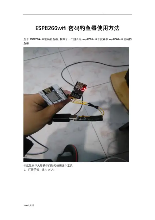
ESP8266wifi密码钓鱼器使用方法
至于ESP8266wifi密码钓鱼器,我做了一个组合版-esp8266wifi干扰器和esp8266wifi密码钓鱼器
在这里家华大哥教你们如何使用这个工具
1.打开手机,进入WLAN
连接wifi Tenda 607098,密码112233445566 2.进入浏览器,进入网址192.168.4.1
点击“开始”按钮,扫描wifi
3.等待15秒后,点击目标wifi对应的“select”按钮,如下图
点击“攻击”选卡
点击deauth的“开始”按钮,干扰目标wifi 4.连接wifi,名称HH,密码m1234567
5.进入浏览器,输入网址192.168.1.1/backdoor.html
6.等待10秒后,输入目标wifi编号,勾选TP LNK,其它的那两个也行,然后点击确认。
随后esp8266钓鱼器上的蓝灯会常亮,打开WLAN,你会发现有一个与目标wifi同名的钓鱼wifi。
6.当esp8266钓鱼器上的蓝灯熄灭时,打开WLAN,会发现钓鱼wifi消失了,HH重新出现。
这说明wifi主人连上了钓鱼wifi,并成功钓到wifi密码。
.
7.重新连接HH,再次进入网址192.168.1.1/backdoor.html
目标wifi密码就会显示在左上角的“登‐〉〈‐录”处。
6.拔掉wifi干扰器,用钓来的wifi密码连接目标wifi。
注意:所有符号都用英文符号!!!
Word文档。
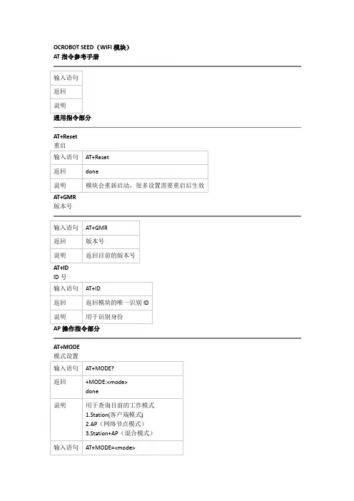
OCROBOT SEED(WIFI模块)AT指令参考手册
通用指令部分
AT+Reset
版本号
AP操作指令部分
AT+MODE
AT+ExtAP
退出网络
AT+SAP
配置模块为可登陆的wifi热点(仅在AP与Station+AP模式下有效)
TCP/IP指令部分
AT+MUX
配置单链接模式或者多链接模式(一般使用推荐配置成单链接模式,使用简单)
建立TCP或者UDP链接
单链接模式下
多链接模式
获取链接状态
AT+UpDate 发送数据
多链接模式
关闭链接
单链接模式
建立服务器,接受数据(请注意:一定要开启多链接模式才能启用)
其他显示指令
+IPD指令
这个指令为系统收到数据的自动返回指令格式如下+IPD,<数据长度>,<数据> +IPD,<链接ID>,<数据长度>,<数据>。


拿到模块我们开始吧编写人:张松审核人:王崇版本:20161224V1.2目录简介 (2)第一章接线篇 (3)1.1接线 (3)1.2测试 (3)第二章AT指令使用几种例子 (5)2.1模块ap模式下做tcp serve (5)2.2模块sta模式下做tcp serve (6)2.3模块tcp client透传模式 (6)2.4模块UDP多连接模式 (8)2.5模块UDP透传模式 (10)2.6两个模块UDP传输模式 (11)第三章常用指令及安信可新增指令篇 (14)3.1AT常用 (14)第四章模块固件烧录篇 (15)第五章模块环境开发篇 (16)第六章如何写一个hello word! (22)第七章硬件参考设计 (23)第八章常用资料说明 (26)第九章常见问题 (27)简介这是主要真对安信可的出厂模块(并非开发板)进行的个人总结,如有不明白和错误可以加群8266技术支持群(383531883)给群主张松留言,我会经常更新一些大家常见的问题和怎么去玩ESP8266等。
第一章接线篇1.1接线拿到我们模块后,请按以下接线进行测试,即VCC、EN接3.3v、GPIO15GND接地、模块的TX、RX接串口工具的RX、TX、RST引脚低电平复位,不需要可以悬空、GPIO0下载固件时要拉低(温馨提示:如果您购买的是ESP-01S/07S/08S/12S只需要接VCC GND RX TX既可正常工作)。
如果您购买的是ESP-01模块只需要把CH-PD接到VCC上。
其他的按照下图接线即可(没有的IO可以不接)。
如下图:1.2测试在以上接线OK的情况下,打开串口调试助手,配置模式为波特率:115200、数据位:8校验位/停止位/流控:none,给模块上电,串口打印信息如下:此时,打开手机,可以搜到Ai-Thinker_XXXX开头的wifi热点(开发板是没有wifi信号的。
上电默认为station模式),两者均可证明模块已正常启动,接下来就为大家介绍常用的功能!指令发送的时候记得发送换新行,或者回车换行。
ESP8266用户手册ESP8266是一种广泛使用的无线模块,由Espressif Systems开发,被广泛使用于物联网和嵌入式设备的应用。
ESP8266的设计目标是为IoT应用提供连接便捷、底层可编程性和低成本的方案,它采用了Tensilica的L106 Diamond系列的32位大小端MCU。
由于其强大的功能和易于使用性,ESP8266已经成为了DIY电子爱好者的最爱。
本文将详细介绍ESP8266用户手册,以帮助新手更好地使用该模块。
1. 硬件介绍ESP8266是一款集成了Wi-Fi的芯片,它与主控芯片之间通过串行通信进行交互。
ESP8266的主体尺寸为16mm x 24mm,并且它的引脚和结构都是十分紧凑的。
ESP8266通常工作在3.3V的电压下,但是如果需要与5V的主控芯片进行通信,就需要进行电平转换。
2. 软件介绍在软件方面,ESP8266支持多种开发平台和语言。
目前,ESP8266最受欢迎的开发平台是Arduino IDE,用户可以通过该平台进行快速的开发工作。
此外,ESP8266也支持其他语言和开发平台,例如Python、Lua等。
3. WiFi模式ESP8266支持三种WiFi模式: STA模式、AP模式和STA+AP 模式。
STA模式是指将ESP8266作为一个WiFi的客户端连接到一个现有的WiFi网络,AP模式是指将ESP8266作为一个WiFi热点使其它设备可以连接到它,STA+AP模式是指将ESP8266同时作为WiFi客户端和WiFi热点。
4. AT指令ESP8266可以通过AT指令进行控制。
当我们要将ESP8266作为单片机处理时,我们可以使用AT指令来控制它的各种功能。
AT指令通常以“AT”开头,其后跟着具体的指令。
例如,AT+GMR是一个用来获取ESP8266固件版本信息的指令。
5. 固件升级在使用ESP8266过程中,我们可能需要升级不同版本的固件以获取新的功能和修复BUG。

高性能UART-WIFI 模块ATK-ESP8266 WIFI 用户手册User Manual目录1.特性参数 (1)2.使用说明 (2)2.1模块引脚说明 (2)2.1安信可ESP8266-12F WIFI模块 (3)2.2模块使用说明 (4)2.2.1 功能说明 (4)2.2.1.1 透传模式 (4)2.2.2 使用前准备 (4)2.2.3 硬件连接 (4)2.2.4 指令结构 (5)2.2.3 基础AT指令 (5)2.2.3.1 AT (5)2.2.3.2 AT+RST (6)2.2.3.3 AT+GMR (6)2.2.3.4 ATE (6)2.2.3.5 AT+RESTORE (6)2.2.3.6 AT+UART (6)2.2.4 WIFI功能AT指令 (7)2.2.4.1 AT+CWMODE (8)2.2.4.2 AT+CWJAP (8)2.2.4.3 AT+CWLAP (9)2.2.4.4 AT+CWQAP (9)2.2.4.5 AT+CWSAP (9)2.2.4.6 AT+CWLIF (10)2.2.4.7 AT+CWDHCP (10)2.2.4.8 AT+CW AUTOCONN (11)2.2.4.9 AT+CIPSTAMAC (11)2.2.4.10 A T+CIPAPMAC (11)2.2.4.11 A T+CIPSTA (12)2.2.4.12 A T+CIPAP (12)2.2.4.13 A T+SA VETRANSLINK (12)2.2.5 TCP/IP工具箱AT指令 (13)2.2.5.1 AT+CIPSTA TUS (13)2.2.5.2 AT+CIPSTART (14)2.2.5.3 AT+CIPSEND (15)2.2.5.4 AT+CIPCLOSE (15)2.2.5.5 AT+CIFSR (16)2.2.5.6 AT+CIPMUX (16)2.2.5.7 AT+CIPSERVER (16)2.2.5.8 AT+CIPMODE (17)2.2.5.9 AT+CIPSTO (17)2.2.5.10 A T+CIUPDA TE (17)2.2.5.11 A T+PING (18)2.2.6 基本AT指令测试 (18)2.2.6.1 AT+RST 重启模块,如图2.2.6.1.1 (19)2.2.6.2 AT+GMR 查看版本信息,如图2.2.6.2.1 (19)2.2.7 TCP Client透传模式 (19)2.2.8 多连接server (23)3 结构尺寸 (26)4 其他 (26)1.特性参数ATK-ESP8266是ALIENTEK推出的一款高性能的UART-WiFi(串口-无线)模块,ATK-ESP8266板载ai-thinker公司的ESP8266模块,该模块通过FCC,CE认证,可直接用于产品出口欧美地区。

ESP8266串口wifi模块,一对一或一对多通信AT指令配置说明史晓冬由B箱:****************介绍在本例中使用至少两个ESP8266模块其中模块1配置为AP模式,并创建一个服务器serveri。
模块2配置为STA模式,作为客户端clienti加入模块1创建的AP后与服务器serveri建立TCP连接,之后模块1和模块2可以通信。
模块3与模块2配置类似,模块3配置为STA模式,作为客户端client2加入模块1创建的AP,之后与serveri建立TCP连接,模块1和模块3可以通信。
ESP8266作为服务器最多可以连接5个客户端。
说明:ESP8266模块通过串口与TTL转USB模块(在调试时使用了CH340和CPL2003,两者均可)相连,然后连接到PC端。
使用串口调试助手对ESP8266进行AT指令的配置。
串口设置:波特率:115200停止位:1数据位:8奇偶校验:无串口调试助手设置为“发送新行”。
模块1设置,模式:AP模式,server服务器。
模块1通过CH340与PC相连后,打开串口调试助手,本历程中使用正点原子的XCOMV2.0;选择对应的com端口,对串口参数设置好。
如图1。
打开串口后,发送,“AT”,测试模块是否连接成功,如果返回“OK”则说明连接成功。
如下图:设置模式为AP模式,发送AT指令“AT+CWMODE=2",返回“OK”,说明配置成功。
如图:设置AP参数,热点名称为“ESP8266” ;密码为“123456789",通道号11,加密方式3;AT指令为:AT+CWSAP="ESP8266","123456789",11,3如图:返回“OK”设置成功。
重启模块使AP设置生效。
指令:AT+RST;如图:靛XCOM V2.0单条发送多条发送协议传输帮助AT+RST启动多链接。
AT指令为:AT+CIPMUX=1 如图:配置为TCP 服务器,端口号8080指令为:AT+CIPSERVER=1,8080 如图:Ai-Thiiiker Technclogy Co., Ltd. re alyNT 十匚工FMUK=1OKAT+GIFSERV^R=l, 8080 OK单荥发法薛条发送协议传输帮助kT+CIFSERVE^l, 3030获取本地IP 地址: 指令:AT+CIFSR 如图:定时发送周期:1 口口口口ms16进制发送7发送新行0%打开文件I Ij 产瀛电子网;wvuw. ope n edv. coms :g&R :5gBCTS=1 口 £R=1 DCD=1 当亩在返回的参数中,APIP为本地的IP地址,此地址将在模块2中建立TCP连接时使用。

安信可ESP8266模块使用指导ESP8266是一款低成本、低功耗的Wi-Fi模块,具有强大的处理能力和丰富的接口选项。
在这篇使用指导中,将向您介绍如何使用安信可ESP8266模块进行Wi-Fi通信。
1.硬件准备首先,您需要准备以下硬件设备:-安信可ESP8266模块-电脑或单片机开发板-USB转串口模块(用于连接ESP8266模块和电脑)2.硬件连接将ESP8266模块与USB转串口模块进行连接。
请确保连接正确,例如将ESP8266的VCC引脚连接到3.3V电源,GND引脚连接到地线,TX引脚连接到USB转串口的RX引脚,RX引脚连接到TX引脚。
3.软件准备在开始编程之前,您需要安装以下软件:- Arduino IDE(用于编写和上传代码)- ESP8266 Arduino核心库(用于支持ESP8266模块)安装完成后,打开Arduino IDE并选择适用于ESP8266的开发板。
4.编写代码以下是一个简单的示例代码,用于将ESP8266连接到Wi-Fi网络并发送HTTP请求:```Arduino#include <ESP8266WiFi.h>const char* ssid = "你的Wi-Fi名称";const char* password = "你的Wi-Fi密码";void setudelay(10);WiFi.begin(ssid, password);while (WiFi.status( != WL_CONNECTED)delay(500);Serial.print(".");}Serial.println("");Serial.println("Wi-Fi连接成功");Serial.println("发送HTTP请求...");WiFiClient client;client.println("GET /api/data HTTP/1.1");client.println("Connection: close");client.println(;}void loo//其他代码...```5.上传和运行代码将ESP8266模块连接到电脑,并在Arduino IDE中选择正确的串口和开发板。

ESP8266串口wifi模块使用手册
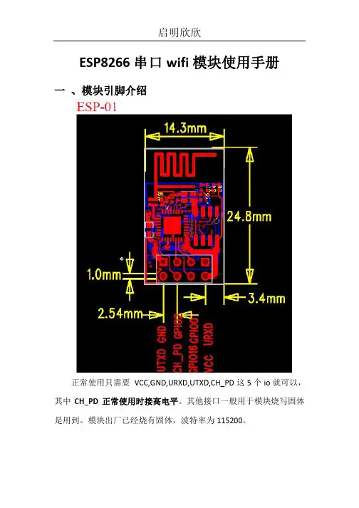
一、模块引脚介绍
正常使用只需要VCC,GND,URXD,UTXD,CH_PD这5个io就可以,其中CH_PD正常使用时接高电平。
其他接口一般用于模块烧写固体是用到。
模块出厂已经烧有固体,波特率为115200。
二、模块与407开发板(高配版)V3.1连接
由于wifi模块接口与网络芯片DP83838公用IO口,所以在使用wifi模块时,需要把P5,上图红色圈出来的短路帽全部拆掉,不要接。
三、实验操作与现象
1、P5短路帽全部拆掉
2、板子上电,下载配套的例程程序
3、板子断电,插上wifi模块
4、板子上电后,代码运行配置wifi模块工作在服务器
5、此时手机wifi搜索,可搜索到名为“qiming_wifi”的热点,连接此热点,密码为:0123456789
6、打开“启明WIFI”app,输入IP: 192.168.4.1 端口号5000
7、点击“连接”,连接成功后手机APP就可以控制开发板了第5、6步可以在程序中设置用户自己所需参数。

ESP8266 Phy Init Bin Parameter Configuration GuideVersion 1.0Espressif SystemsCopyright © 2018About This Guide This guide provides the parameter configuration for ESP8266 phy init bin.Release NotesDate Version Release notes2018.12V1.0Initial releaseDocumentation Change NotificationEspressif provides email notifications to keep customers updated on changes totechnical documentation. Please subscribe at https:///en/subscribe.CertificationDownload certificates for Espressif products from https:///en/certificates.Table of Contents....................................................................................... 1.Structure of ESP8266 Phy Init Bin 1.................................................................................... 2.Check Bits for ESP8266 Phy Init Bin 2.......................................................................................... 3.Version of ESP8266 Phy Init Bin 3............................................................................................... 4.Selection of Crystal Oscillator 4.......................................................................................................... 5.Six Levels of TX Power 5.......................................................................................... 6.TX Power for Various Data Rates 6.................................................................................................................... 7.TX Power Limits 7..........................................................................................7.1.Value Range of the TX Power Limits 77.2.Parameters for the TX Power Limits 7................................................................................................................................................................................................................. 8.RF Calibration 91. Structure of ESP8266 Phy Init Bin 1.Structure of ESP8266 Phy InitBin ESP8266 phy init bin is comprised of a 128-byte phy init data as shown in Table 1-1:Table 1-1. Structure of ESP8266 Phy Init BinName Sizephy init data128 bytes2. Check Bits for ESP8266 Phy Init Bin 2.Check Bits for ESP8266 PhyInit Bin The check bits for ESP8266 phy init bin are stored in byte zero of phy init data, and therelevant parameter is Init_bin_magic with default value of 0x5. The check bits are used forverifying the data location in ESP8266 phy init bin. If the parameter value is the same asthe default value when reading data, it is assumed that data are stored correctly inESP8266 phy init bin.Table 2-1. Check Bits for ESP8266 Phy Init BinLocation in phy init data Parameter Name Default Value Description0Init_bin_magic5For check3. Version of ESP8266 Phy Init Bin3.Version of ESP8266 Phy InitBinThe version information of ESP8266 phy init bin is stored in byte 1 of phy init data.For example, ESP8266_esp_data_bin_v08.bin represents Version 08, which is stored inbyte 1 as 0x8.Table 3-1. Version of ESP8266 Phy Init BinLocation in phy init data Parameter Name Default Value Description1Init_bin_version8phy init bin version4. Selection of Crystal Oscillator 4.Selection of Crystal OscillatorThe parameter crystal_sel allows you to select a crystal oscillator. The available options aregiven in Table 4-1. Currently, ESP8266 mainly supports 26 MHz and 40 MHz crystaloscillators.Table 4-1. Selection of Crystal OscillatorLocation in phy init data Parameter Name Default Value Description48crystal_sel10: 40 MHz crystal oscillator 1: 26 MHz crystal oscillator 2: 24 MHz crystal oscillator5. Six Levels of TX Power 5.Six Levels of TX PowerTX power can be switched between six levels. The indexes for the six levels are thenumbers from 0 to 5 at the end of the parameter names. For example, the index fortxpwr_qdb_0 is 0, representing the maximum TX power. From txpwr_qdb_0 totxpwr_qdb_5, the TX power decreases progressively.Default TX power settings can be found in Table 5-1.Table 5-1. Six Levels of TX PowerLocation in phy init data Parameter Name Default Value Unit Actual TX Power34txpwr_qdb_0780.25 dB19.5 dBm35txpwr_qdb_1740.25 dB18.5 dBm36txpwr_qdb_2700.25 dB17.5 dBm37txpwr_qdb_3640.25 dB16 dBm38txpwr_qdb_4600.25 dB15 dBm39txpwr_qdb_5560.25 dB14 dBm6. TX Power for Various Data Rates 6.TX Power for Various DataRates You can choose from any of the six TX power levels for different data rates. The columnDefault value in Table 6-1 contains the TX power index.Table 6-1. TX Power for Various Date RatesLocation in phy init data Parameter Name Data rate/mode DefaultValueDescription40txpwr_index_0MCS0, 1 Mbit/s, 2 Mbit/s, 5.5 Mbit/s, 11 Mbit/s,6 Mbit/s, 9 Mbit/s0Select txpwr_qdb_041txpwr_index_1MCS1, 12 Mbit/s0Select txpwr_qdb_0 42txpwr_index_2MCS2, 18 Mbit/s1Select txpwr_qdb_1 43txpwr_index_3MCS3, 24 Mbit/s1Select txpwr_qdb_1 44txpwr_index_4MCS4, 36 Mbit/s2Select txpwr_qdb_2 45txpwr_index_5MCS5, 48 Mbit/s3Select txpwr_qdb_3 46txpwr_index_6MCS6, 54 Mbit/s4Select txpwr_qdb_4 47txpwr_index_7MCS75Select txpwr_qdb_596txpwr_index_11b_en802.11b00: use txpwr_index_0 toset TX Power for 802.11b1: use bytes 97 and 98 toset TX Power for 802.11b97txpwr_index_11b_01 Mbit/s,2 Mbit/s0Select txpwr_qdb_098txpwr_index_11b_15.5 Mbit/s, 11 Mbit/s0Select txpwr_qdb_07. TX Power Limits7.TX Power LimitsThe TX power limits have been set mainly to limit the maximum powers for channels 1, 11,13 and 14 in order to conform to the certification test results.7.1.Value Range of the TX Power LimitsThe TX power limits are set against the six levels. The value range of the limits is [0:5],which includes the values presented in Table 7-1.7.2.Parameters for the TX Power LimitsThe parameters for the TX power limits are specified in Table 7-2. For example, if the valueof byte 78 is set to 2, the bytes 30-33 are enabled to configure the maximum TX powers for channels 1, 11, 13 and 14.Table 7-1. Values of the TX Power Limits ValueTX Power Limit (Unit: 0.25 dB)0txpwr_qdb_01txpwr_qdb_12txpwr_qdb_23txpwr_qdb_34txpwr_qdb_45txpwr_qdb_5Table 7-2. Parameters for the TX Power Limits Location inphy init data Parameter name Default value Description78fcc_enable 00: disable bytes 30-331: reserved2: enable bytes 30-33 to set maximum TXpower30mpwr_chan10Set the maximum TX power for 802.11 b/g/n mode at channel 1, range [0:5]. 0xf8 isan invalid parameter.31mpwr_chan110Set the maximum TX power for 802.11 b/g/n mode at channel 11, range [0:5]. 0xf8is an invalid parameter.7. TX Power Limits32mpwr_chan130Set the maximum TX power for 802.11 b/ g/n mode at channel 13, range [0:5]. 0xf8 is an invalid parameter.33mpwr_chan140Set the maximum TX power for 802.11 b/ g/n mode at channel 14, range [0:5]. 0xf8 is an invalid parameter.8. RF Calibration 8.RF CalibrationThe values of the parameter RF_calibration are shown in Table 8-1. To ensure better RFperformance, it is recommend to set RF_calibration to 3, otherwise the RF performancemay become poor.Table 8-1. Parameter of RF CalibrationLocation inphy init dataParameter name Default value Description114RF_calibration30 & 1: only used for setting TX power 2: No RF calibration3: Conduct all RF calibrationDisclaimer and Copyright NoticeInformation in this document, including URL references, is subject to change without notice.THIS DOCUMENT IS PROVIDED AS IS WITH NO WARRANTIES WHATSOEVER,INCLUDING ANY WARRANTY OF MERCHANTABILITY , NON-INFRINGEMENT, FITNESS FOR ANY PARTICULAR PURPOSE, OR ANY WARRANTY OTHERWISE ARISING OUT OF ANY PROPOSAL, SPECIFICATION OR SAMPLE.All liability, including liability for infringement of any proprietary rights, relating to use of information in this document is disclaimed. No licenses express or implied, by estoppel or otherwise, to any intellectual property rights are granted herein.The Wi-Fi Alliance Member logo is a trademark of the Wi-Fi Alliance. The Bluetooth logo is a registered trademark of Bluetooth SIG.All trade names, trademarks and registered trademarks mentioned in this document are property of their respective owners, and are hereby acknowledged. Copyright © 2018 Espressif Inc. All rights reserved.Espressif IoT Team。
ESP8266 WiFi模块用户手册目录术语和缩写 ....................................................... 错误!未定义书签。
1. 产品简介 ......................................................... 错误!未定义书签。
. 概述 ......................................................... 错误!未定义书签。
产品特性 ................................................. 错误!未定义书签。
模块封装 ................................................. 错误!未定义书签。
模块基本参数 ............................................. 错误!未定义书签。
. 硬件介绍 ..................................................... 错误!未定义书签。
. 功耗 ......................................................... 错误!未定义书签。
. 射频指标 ..................................................... 错误!未定义书签。
. 尺寸 ......................................................... 错误!未定义书签。
. WiFi 天线 .................................................... 错误!未定义书签。
. 推荐炉温曲线 ................................................. 错误!未定义书签。
Your ESP8266 is an impressive, low cost WiFi module suitable for adding WiFi functionality to an existing microcontroller project via a UART serial connection. The module can even be reprogrammed to act as a standalone WiFi connected device–just add power!The feature list is impressive and includes:802.11 b/g/n protocol Wi-Fi Direct (P2P), soft-APIntegrated TCP/IP protocol stackThis guide is designed to help you get started with your new WiFi module so let’s start!The hardware connections required to connect to the ESP8266 module are fairly straight-forward but there are a couple of important items to note related to power:The ESP8266 requires 3.3V power–do not power it with 5 volts!The ESP8266 needs to communicate via serial at 3.3V and does not have 5V tolerant inputs,so you need level conversion to communicate with a 5V microcontroller like most Arduinos use.However , if you’re adventurous and have no fear you can possibly get away with ignoring the second requirement. But nobody takes any responsibility for what happens if you do. :)Here are the connections available on the ESP8266 WiFi module:ESP8266 WiFi Module Quick Start GuideIntroductionHardware ConnectionsNOTE:Links and Code (Software) Supplied or Referenced in this Document is supplied as a service to our customers and accuracy is not guaranteed nor is it an Endorsement of any particular part, supplier or manufacturer. Use of information and suitability for any application is at users own discretion and user assumes all risk.All rights are retained by the AuthorWhen power is applied to the module you should see the red power light turn on and the blue serial indicator light flicker briefly.If you have a 3.3V FTDI Serial to USB board you can get started without fear of destroying your new ESP8266 WiFi module. Do note that many FTDI boards have a solder jumper to convert from 3.3V to 5V operation so ensure it is set to enable 3.3V operation.Here are the connections required to enable communication with the module over serial:With FTDI 3.3V Board (Legit)DO NOT DO THIS! You may break your Arduino or your ESP8266 WiFi module.This method is a bad idea for a number of reasons:The ESP8266 does not have 5V tolerant inputs–you could destroy your WiFi module.The ESP8266 may draw more current than the 3.3V regulator on your Arduino can supply–you could damage your Arduino.The operation of the ESP8266 outside of stated limits may be unstable and unreliable–you could damage your sanity.This method does have one redeeming feature:If you already have an Arduino Uno R3 it’s really easy to get started and (mostly) worked for me. :)We’re essentially going to use your Arduino as a power supply and USB to serial converter so you need to ensure there is no sketch that interferes with the serial connection. There are a couple of ways to achieve this:Upload an “empty” sketch that doesn’t use the serial connection, e.g. BareMinimum from theWith Arduino Uno R3 (Quick but not very legit)examples menu; or,Remove the microcontroller from the Arduino board (if it is a DIP form factor–don’t undersolder an SMD one).Here are the connections required to enable communication with the module over serial in this configuration:Serial ControlWith the hardware connections in place you can communicate with the WiFi module through a serial terminal.Using Arduino IDE Serial MonitorIf you already have the Arduino IDE installed the easiest way to get started is to use the built-in Serial Monitor:1. Plug in the WiFi module.2. Choose the correct serial port from the Tools > Serial Port menu.3. Open the Serial Monitor via the Tools menu or “magnifying glass” icon on the editor window.4. For the default firmware version (00160901), ensure Carriage return is selected in the lineending pop-up menu at the bottom of the serial monitor. (For later versions it must be set toBoth NL & CR.)5. For the default firmware version, ensure the communication speed is set to 115200 baud. (Forlater versions or if it has been modified it will need to be 9600 baud or similar.)You’re now ready to send your first commands!Using GNU ScreenIt’s possible to use GNU Screen out of the box with the default version of the firmware (00160901) which expects Carriage-Return-only line endings, e.g. (on OS X):screen /dev/bserial-AB12345 115200Unfortunately the updated firmware versions require Carriage-Return-and-New-Line line endings and there appears to be no way to configure screen to send both with one key press. Instead, you need to press <enter> or Ctrl-M then follow that with Ctrl-J.You might have more success with something like minicom or picocom with later firmware versions.Now you’re ready to send your first commands!First Commands1. Ensure AT commands are received correctly (the AT seems not to be case sensitive but therest of any command is case sensitive):ATResponse:OKIf you don’t get this response check:Hardware connections (the blue LED on the board should flash). Try swapping RX & TX.Correct baudrate–should be 115200 on the default firmware version (00160901).Correct line endings–should be Carriage Return only for default firmware version (00160901).If it still doesn’t work, give up, you’ve probably got better things to do with your life…2. Ensure the module is in a known state by issuing a reset command:AT+RSTResponse:ets Jan 8 2013,rst cause:4, boot mode:(3,6)wdt resetload 0x40100000, len 24444, room 16tail 12chksum 0xe0ho 0 tail 12 room 4load 0x3ffe8000, len 3168, room 12tail 4chksum 0x93load 0x3ffe8c60, len 4956, room 4tail 8chksum 0xbdcsum 0xbdreadyOr similar. The important part is the ready on the last line.3. Check the firmware version:AT+GMRThe stock firmware produces this output:001609014. Enable the module to act as both a “Station” and an “Access Point”:AT+CWMODE=3Response:OK(You may need to perform another reset after changing this setting.)5. List surrounding WiFi networks.First, if you’re on (at least) the 00160901 firmware you need to work around an apparent firmware bug that hangs on listing WiFi networks if the last joined network is no longer available.The following command ensures no network details are stored for connection (you should get an OK) response:AT+CWJAP="",""(You can check to see what the currently stored network details are with:AT+CWJAP?which should generate the following output if no network details are stored:+CWJAP:""With a later firmware or if the last joined network is still in the vicinity you shouldn’t need to do this pre-step.)Now you send the actual command to list networks in the vicinity:AT+CWLAPYou should get a response like:+CWLAP:(0,"",0)+CWLAP:(3,"WiFiArtThouRomeo",-80)+CWLAP:(3,"Free Public WiFi",-51)+CWLAP:(3,"Guest",-91)OKSometimes you might get ERROR or no response–in which case you’ll have to try doing the USB plug/unplug cycle and try again. (Or the same with the ground jumper.)6. Join a suitable WiFi access point:AT+CWJAP="<access_point_name>","<password>"You should get an OK response.For example, with the above list of access points you might use:AT+CWJAP="Guest","MyVoiceIsMyPasswordSoWhyDoINeedThis?"You can check if the module has been allocated a IP address with:AT+CIFSRYou should get your current IP address in response, e.g:192.168.1.2Acting as a TCP ClientYou can connect to an internet server (e.g. a web server) with the following method:1. Enable multiple connections (you need an OK response):AT+CIPMUX=12. Specify which connection channel you wish to connect on (0-4), the protocol type (TCP/UDP),the IP address (or domain if you have DNS access) and the port number using the CIPSTART command:AT+CIPSTART=4,"TCP","",80You should receive the response OK followed by Linked when the connection is open:OKLinked3. Next you need to specify how much data you wish to send (after specifying which channel). In thisexample we’re going to send “GET / HTTP/1.0\r\n\r\n” which is 18 bytes:AT+CIPSEND=4,18This time, instead of an “OK” response your will get a > prompt:>This indicates the module is waiting for you to send the 18 bytes of data.Here it gets a bit messy if you’re using the Arduino serial monitor as you have to swap between the line ending the module requires (“Carriage return” only) and what the HTTP server is expecting (“Both NL & CR”). Change the setting to Both NL & CR and send the following (you will need to press Send a second time to send the empty line the HTTP server expects):GET / HTTP/1.0The module should respond with:SEND OKNow you should change the line ending setting to Carriage return only so you can send additional commands.The module should provide a second response once the web server responds:+IPD,4,530:The 4 indicates it’s data from connection channel 4 and the 530 indicates there’s 530 bytes of data. You should now see the data:HTTP/1.0 302 FoundCache-Control: privateContent-Type: ...Woo! You just put a thing on the internet…time to go find a VC!You’ll likely get an OK response or two and then eventually an indication that the server has closed the connection:UnlinkActing as a TCP ServerYou can enable the module to accept TCP connections (i.e. act as a server) in the following manner:1. Connect to a WiFi access point.2. Enable multiple connections.AT+CIPMUX=13. Find out the IP address of the module:AT+CIFSRNote the response, e.g.:192.168.1.24. Set the module to listen (first parameter, mode is set to 1) for a connection on a specific port(in this case port 1336):AT+CIPSERVER=1,13365. From another device on the same network connect to the listening port, e.g. with telnet:telnet 192.168.1.2 1336The module should display:LinkType some text into the telnet session, e.g.:KiwiconAte!The module should display the following (0 being the connection channel, 13 being the length of the data received:+IPD,0,13:KiwiconAte!OKYou can send data in response with the CIPSEND command as used previously, e.g. (0 is the channel, 8 is the length of the data):AT+CIPSEND=0,8The module will display the prompt:>Then you can send the data, e.g.:WhatEvsAnd then the module will respond with:SEND OKThe telnet session should now display:WhatEvsYou can then end the telnet session with by pressing Ctrl-] and q<enter>, the module will display:UnlinkActing as a WiFi Access PointIn addition to connecting to WiFi Access Points the module can also act as an Access Point–this means you can connect devices to the module without any other network infrastructure in place. Ideal for a local private shared “drop box” perhaps…1. The module comes with an access point pre-defined (SSID of “ESP_…”) but you can define yourown with:AT+CWSAP="NoWorriESSID","password",3,0The first parameter is the SSID name; the second parameter is the password; the third the WiFichannel–pick one not used in your area; and, the final parameter is the encryption standard to use.An encryption value of 0 turns encryption off which means the password is ignored–but it still can’t be an empty value. I couldn’t get any encryption to work though (it would always create an unencrypted network) you might have more luck–possibly with a more recent firmware…2. To actually enable the network to be created you need to set the “WiFi mode” of the module to “AP”(2) or “Both” (3):AT+CWMODE=3Now you will be able to connect to your module as an access point from another device (e.g. a laptop or a phone).3. You can list the IP address etc of any device connected to the network with:AT+CWLIFWhich generates the response:192.168.4.100, [...]4. Now you can run the server example from above and connect–note that the module always has theIP 192.168.4.1 when acting as an AP.Updating the firmwareYou’ll be pleased to know you’re not stuck with the ample list of features that ship with your module, no, because you can update the firmware of your module! Yes, that means you can get new features & new bugs too…Finding New Official FirmwareIt’s not particularly easy to find new official firmware versions–the links are spread over forums, wikis and Google Drive accounts which don’t look particularly legit.It seems like the best source of details is the “Updates” section of the “Firmware” section on this page: /w/Wi07c#FirmwareThis ridiculous URL (from the link entitled “Find most upated firmware on this google link” on the above ElectroDragon page) seems to list all the official firmware updates: https:///folderview? id=0B3dUKfqzZnlwR2pVWjg3NXRVdW8&usp=drive_web&tid=0B3dUKfqzZnlwRjFaNTUzZFptbzg#listConsider uploading one of the following versions:ESP8266_flasher_V00170901_00_Cloud Update Ready.zipESP8266_AT_V00180902_02_baudrate watchdog added.zip(A note on version numbers: the version number 00160901 is made up of two parts: 0016 is theSDK version and 0901 is the AT command set version.)Once you’ve updated the firmware you also have the option of “Cloud Updates” but I’ve not managed to get any cloud update to work yet: /cloud-updating-your-wi07c-esp8266-now/Firmware Update ToolsWhile there are other tools for updating the firmware, for this example we’ll use esptoolhttps:///themadinventor/esptool/ which is cross platform and GPL licensed.Download the script file fromhttps:///themadinventor/esptool/master/esptool.py.Hardware Connections and Performing the UpdateIn order to update the firmware you need to configure the hardware to enter firmware update mode:1. Disconnect the module from your computer.2. Connect GPIO0 to ground (0 Volts) (“pulled low”) to enable firmware update mode.3. Reconnect the module to your computer.The module should now be in firmware update mode.(Note that the esptool docs say to ensure “GPIO2 is pulled high” but this doesn’t appear to be necessary.)Execute this command to perform the firmware update (the .bin file is from theESP8266_AT_V00180902_02_baudrate watchdog added.zip archive):python esptool.py --port /dev/bserial-ABC12345 write_flash 0x000000 " v0.9.2.2 AT Firmware.bin"You should receive progress updates during the upload process:Connecting...Erasing flash...Writing at 0x0007ec00... (100 %)Leaving...If you have problems connecting and have been using the Arduino IDE Serial Monitor ensure it isn’t open when trying to perform the upgrade. (Ask me how I know…)Once the update has completed:1. Disconnect the module from your computer.2. Remove the connection from GPIO0 to ground.3. Reconnect the module to your computer.You should now have a new firmware version installed and functioning.Note:The startup behaviour of the module is now different–it displays different output.The module now defaults to communicating at 9600 baud.The module now expects both carriage return and new line characters at the end of every line.New AT commands will be available and some bugs may have been fixed!Arduino and ESP8266Up until now you’ve been manually controlling the WiFI module via the serial console. It’s obviously possible to control the module programmatically via an Arduino sketch. At present there doesn’t seem like a “preferred” choice for an Arduino library to abstract the functionality but a few searches will find you Arduino examples to start with and presumably over time the Arduino community will settle on a preferred library.ESP8266 SDK and Custom FirmwareAn official Software Development Kit (SDK) has been released for the System-on-Chip (SoC) controller which powers the ESP8266 WiFi module. Using the SDK it’s possible to add extra features to the AT command firmware or even create a standalone firmware.Here’s a couple of custom firmwares to check out…NodeMcuLua based firmware for WiFi-SoC ESP8266: https:///nodemcu/nodemcu-firmwareVery cool and easy to get started with.Download the firmware:wget https:///nodemcu/nodemcu-firmware/raw/master/0.9.2/512k-flas h/nodemcu_512k.binFlash the firmware to the module:python esptool.py --port /dev/bserial-ABC123456 write_flash 0x000000 nodemcu_512k.binConnect to the module:screen /dev/bserial-ABC123456 9600Do the obvious…print("hello")For more details look at:https:///nodemcu/nodemcu-firmware#readmehttps:///nodemcu/nodemcu-firmware/wiki/nodemcu_api_enAT Command GPIO controlThere is a custom firmware with AT commands added to read and write the General PurposeInput/Output (GPIO) pins available–this enables you to control LEDs and read buttons with AT commands.For more details see: /esp8266-gpio-test-edited-firmware/More resourcesEspressif Systems (Designer): https:///en/products/esp8266/Espressif Systems Github: https:///espressifESP8266 Community Forum: /NURDspace on ESP8266: https://nurdspace.nl/ESP8266First setup of ESP8266 SDK: https://nurdspace.nl/ESP8266/First_setupElectroDragon on ESP8266: /w/Wi07cFinally…Have fun!Find updates to this guide and more information at /i/follower/p/notes-esp8266. This getting started guide is brought to you by Kiwicon 8 and !。
ESP8266wifi密码钓鱼器使用方法
至于ESP8266wifi密码钓鱼器,我做了一个组合版-esp8266wifi干扰器和esp8266wifi密码钓鱼器
在这里家华大哥教你们如何使用这个工具
1.打开手机,进入WLAN
连接wifi Tenda 607098,密码112233445566 2.进入浏览器,进入网址http://192.168.4.1
点击“开始”按钮,扫描wifi
3.等待15秒后,点击目标wifi对应的“select”按钮,如下图
点击“攻击”选卡
点击deauth的“开始”按钮,干扰目标wifi 4.连接wifi,名称HH,密码m1234567
5.进入浏览器,输入网址http://192.168.1.1/backdoor.html
6.等待10秒后,输入目标wifi编号,勾选TP LNK,其它的那两个也行,然后点击确认。
随后esp8266钓鱼器上的蓝灯会常亮,打开WLAN,你会发现有一个与目标wifi同名的钓鱼wifi。
6.当esp8266钓鱼器上的蓝灯熄灭时,打开WLAN,会发现钓鱼wifi消失了,HH重新出现。
这说明wifi主人连上了钓鱼wifi,并成功钓到wifi密码。
7.重新连接HH,再次进入网址http://192.168.1.1/backdoor.html 目标wifi密码就会显示在左上角的“登‐〉〈‐录”处。
6.拔掉wifi干扰器,用钓来的wifi密码连接目标wifi。
注意:所有符号都用英文符号!!!。
ESP8266_用户手册_V03关键信息项:1、产品名称:ESP82662、版本号:V033、功能描述4、使用方法5、技术规格6、注意事项11 产品介绍ESP8266 是一款高性能、低功耗的 WiFi 模块,为用户提供便捷的无线连接解决方案。
111 主要特点集成 WiFi 功能低功耗设计小巧轻便易于集成到各种设备中112 应用场景智能家居工业控制智能穿戴设备12 功能描述121 WiFi 连接功能支持 24GHz 频段能够连接到各种 WiFi 网络实现稳定的数据传输122 数据处理能力具备一定的数据处理能力,可对接收和发送的数据进行处理123 接口功能提供多种接口,方便与其他设备进行通信13 使用方法131 硬件连接介绍与其他硬件设备的连接方式和注意事项132 软件配置详细说明如何进行软件设置和参数配置133 编程开发提供相关的编程接口和示例代码14 技术规格141 工作电压范围142 工作温度范围143 传输速率144 接收灵敏度15 注意事项151 电源稳定性确保供电电源的稳定性,以避免模块工作异常152 电磁干扰避免在强电磁干扰环境中使用,以免影响 WiFi 信号153 散热问题在长时间工作时,注意模块的散热情况154 软件更新及时关注官方发布的软件更新,以获取更好的性能和功能155 法律法规在使用过程中,遵守相关的法律法规,不得用于非法用途16 故障排除161 连接问题分析 WiFi 连接失败的可能原因和解决方法162 数据传输异常处理数据传输中断或错误的情况17 售后服务提供售后服务的联系方式和服务内容,保障用户在使用过程中的权益。
18 版权声明声明对本用户手册及相关技术的版权归属和使用限制。
以上协议内容仅供参考,您可以根据实际需求进行修改和完善。
Wifi模块使⽤时连接⽅式WIFI连接⽅式(以ESP8266为列)这⾥采⽤AT指令的⽅式进⾏描述,具体AT指令使⽤需要参考8266给的⽂档,这个⼀般买的模块会有相应说明。
第⼀种连接⽅式:wifi作为热点构建局域⽹通信,这时WIFI可作为主机,其他设备作为从机,这时通过AT+CIPMUX可配置多对⼀和⼀对⼀⽅式,需要注意⼀点就是wifi模块会有超时机制,连接建⽴后,需要建⽴⼀个2S的循环数据发送机制,⽤于保持连接。
这时透传模式试过但不⾏。
具体AT指令如下:AT+CWMODE=3AT+RSTAT+CWSAP="ESP8266_TEST","1234567890",1,3AT+CIPMUX=1AT+CIPSERVER=1,8080第⼆种连接⽅式:Wifi连接到路由器作为服务器端,这时在路由器构成的局域⽹内的设备可以互相通信。
同时也可设置多对⼀和⼀对⼀⽅式。
AT+CWMODE=3AT+RSTAT+CIPMUX=1AT+CWJAP="My_router","11111111"AT+CIPSERVER=1,8080第三种连接⽅式:Wifi连接到路由器作为客户端,主机电脑作为服务器端,这时候若电脑上主机IP设置为专⽤IP即192.168.101.110,这时主机与设备之间可以透传,不过也只能在局域⽹内,若TCP连接设置为公⽹其他IP,则可实现外⽹通信。
AT+CWMODE=3AT+RSTAT+CWJAP="My_router","11111111"AT+CIFSRAT+CIPSTART="TCP","192.168.1.183",6602 //电脑主机上要提前设置服务器AT+CIPMODE=1 //透传AT+CIPSENDAT+CIPMUX=1AT+CWJAP="My_router","11111111"AT+CIFSRAT+CIPSTART=0,"TCP","115.29.109.104",6602 //连接外⽹服务器地址。
ESP8266WIFI模块使用说明
使用ESP8266模块前,需要准备好以下内容:
1.一台计算机,用于编程和调试ESP8266模块。
B转串口模块,用于将计算机的USB接口转换成串口接口。
3. 一根Micro USB电源线,用于给ESP8266模块供电。
接下来,我们将详细介绍如何搭建和使用ESP8266模块:
1.硬件连接
a. 将ESP8266模块连接到计算机上的USB转串口模块,通过Micro USB电源线给模块供电。
b.使用杜邦线将USB转串口模块的TXD连接到ESP8266模块的RXD引脚,将RXD连接到TXD引脚,同时将GND引脚连接到ESP8266模块的GND 引脚。
c.注意连接的稳固性,避免松动。
2.ESP8266固件烧录
a.打开计算机上的串口调试助手软件,设置好通信参数(波特率、数据位、校验位、停止位等)。
b.将ESP8266模块复位,打开串口调试助手软件后,会看到模块发送的一系列命令和响应。
如果没有出现乱码,说明串口连接正常。
d.烧录完成后,可以重新复位ESP8266模块,并在串口调试助手软件中输入AT命令来测试模块的功能。
3.AT指令测试
a.在串口调试助手软件中输入AT指令,例如AT+RST,按回车键发送指令给ESP8266模块。
b.模块会返回一些响应信息,例如OK表示指令执行成功,ERROR表示指令执行失败。
c.通过AT指令,可以进行WiFi连接、TCP/IP通信、HTTP请求等各种功能的测试和调试。
4.WiFi连接
a. 输入AT+CWMODE=1,设置ESP8266模块的工作模式为Station模式。
b.输入AT+CWJAP="WiFi名称","WiFi密码",连接到指定的WiFi网络。
c.输入AT+CIFSR,获取ESP8266模块的IP地址。
5.TCP/IP通信
a.输入AT+CIPSTART="TCP","服务器IP地址",端口号,建立与指定服务器的TCP连接。
b.输入AT+CIPSEND,进入发送数据模式。
c.输入要发送的数据,以"+++""结束发送。
d.输入AT+CIPCLOSE,关闭与服务器的TCP连接。
6.HTTP请求
a.输入AT+HTTPINIT,初始化HTTP客户端。
b.输入AT+HTTPPARA="URL","服务器URL",设置HTTP请求的URL地址。
c.输入AT+HTTPACTION=0,发送GET请求。
d.输入AT+HTTPREAD,读取服务器返回的数据。
以上是ESP8266模块的基本使用说明,根据需求,还可以进行更多的功能扩展和开发。
希望以上内容对您有所帮助!。