K641 操作手册
- 格式:pdf
- 大小:52.40 KB
- 文档页数:1

北京德威特电力系统自动化有限公司系统硬件系列说明书DVP–641N/645N北京德威特电力系统自动化有限公司重要提示感谢您使用北京德威特电力系统自动化有限公司的产品。
为了安全、正确、高效地使用本装置,请您务必注意以下重要提示:1) 请仔细阅读本说明书,并按照说明书的规定调整、测试和操作。
如有随机资料,请以随机资料为准。
2) 为防止装置损坏,严禁带电插拔装置各插件、触摸印制电路板上的芯片和器件。
3) 请使用合格的测试仪器和设备对装置进行试验和检测。
4)DVP-600N产品不带防跳继电器,防跳继电器由开关柜配套,或使用DVP-9181操作箱(需在订货中注明)。
5)交流操作时,DVP-600N装置开入电压为DC24V,DC24V电源由装置1端子提供,外部应为无源空接点输入,开入负电源在装置内部,外部(20端子)不接线。
6) 装置如出现异常或需维修,请及时与本公司服务热线联系,(010)80482861。
北京德威特电力系统自动化有限公司目 录1.装置概述 (1)2.技术数据 (1)3.装置结构说明 (5)3.1安装与开孔 (5)3.2装置组成 (6)3.3接线端子图及端子接线说明 (9)3.4显示板(人机交互板) (12)3.5 背板 (12)3.6电源板 (12)3.7处理器板 (12)3.8继电器板 (13)3.9互感器板 (13)4.人机交互 (14)4.1机箱面板说明 (14)4.2按键使用说明 (14)4.3液晶显示内容说明 (16)4.4液晶背光的使用说明 (20)5.CAN网通讯 (20)5.1主机通讯卡通讯波特率设置 (20)5.2装置通讯波特率设置 (21)5.3装置网络状态检查 (21)6.装置与电度脉冲表的连接 (21)7.显示说明 (22)7.1循环显示(供运行人员使用) (22)7.2定点显示(供运行人员或调试人员用) (22)7.3保护定值区显示 (27)北京德威特电力系统自动化有限公司7.4时间设置区显示 (29)7.5事故记录区显示 (30)8. 调试大纲(适用于现场调试及检修) (30)8.1上电显示 (30)8.2查看、输入、校对保护定值 (30)8.3开关量的检查 (31)8.5保护继电器的出口检查 (32)8.6模拟量输入检查及精度检查 (33)8.7保护装置原理框图 (36)8.8装置配备的保护 (40)8.9各类保护的逻辑及实验方法 (40)8.10 连接CAN网 (47)8.11连接电度脉冲表 (48)9.运行人员注意事项及要求 (48)10.检修及维护: (49)11.注意事项 (49)12.订货须知 (50)13.补充说明 (52)14.特殊说明 (55)北京德威特电力系统自动化有限公司DVP-641N/645N 使用说明书 1北京德威特电力系统自动化有限公司 11.装置概述DVP-641N 微机电容器保护监控装置DVP-645N 微机电抗器保护监控装置● DVP-641N 适用于 6~66kV 中性点不接地系统,该装置由监控和保护两套完全独立的系统组成,作为电容器的成套保护、控制、测量和监视报警装置。

国 电 南 自Q/GDNZ.JB051-2011PSL 641U线路保护测控装置技术说明书国电南京自动化股份有限公司GUODIAN NANJING AUTOMATION CO.,LTDPSL 641U线路保护测控装置技术说明书编写审核批准V 1.22国电南京自动化股份有限公司2011年3月版本声明本说明书适用于PSL 641U线路保护测控装置V1.22版本。
a)软件PSL 641U V1.22b)硬件PSL 641U线路保护测控装置硬件模件版本修改记录表序号 模件名称 初始版本(2006-02) 第一次修改版本(2008-08)第二次修改版本1 交流模件 PSL 640U-AC.A-A-11(12)2 CPU模件 E03-CPU.A-A E03-CPU.B-A3 面板模件 E03-PNL.A-A4 DIO模件 PSL 640U-DIO.A-A5 TRIP模件 PSL 640U-TRIP.A-A PSL 640U-TRIP.A-B6 电源模件 EDP 03-PWR.A-A7 母板模件 E03-MB.A-A E03-MB.A-B89PSL 641U线路保护测控装置产品说明书版本修改记录表109876543 V1.22 平台版本升级 PSL 641UV1.22 2011.32 V1.10 改进版本 PSL 641UV1.10 2009.041 V1.00 初始版本 PSL 641UV1.00 2007.04序号说明书版本号修改摘要软件版本号修改日期* 技术支持 电话:(025)51183073传真:(025)51183077* 本说明书可能会被修改,请注意核对实际产品与说明书的版本是否相符* 2007年4月 第2版 第1次印刷* 国电南自技术部监制目 录1概述 (1)1.1保护功能配置 (1)1.2测量和控制 (1)2技术参数 (2)2.1保护元件精确工作范围 (2)2.2保护元件定值误差 (2)2.3保护整组动作时间 (2)2.4通信接口 (2)3保护功能及原理 (3)3.1相间过电流保护 (3)3.1.1相间方向元件 (3)3.1.2低电压闭锁元件 (3)3.1.3负序过电压闭锁元件 (3)3.2相间电流反时限元件 (3)3.3零序过电流 (4)3.3.1零序方向元件 (4)3.3.2零序反时限元件 (4)3.3.3零序电流告警元件 (4)3.4合闸加速 (4)3.5三相重合闸 (4)3.5.1充电条件 (5)3.5.2启动方式 (5)3.5.3重合闸方式 (5)3.5.4闭锁条件 (5)3.5.5二次重合闸 (5)3.6手动同期合闸 (5)3.7低频减载 (6)3.8低压减载 (6)3.9过负荷 (6)3.10小电流接地选线 (7)3.11TV断线 (7)3.11.1母线TV断线 (7)3.11.2线路抽取电压断线 (7)4端子说明 (8)4.1总端子图 (8)4.2交流模件端子X1定义 (8)4.3CPU模件端子X2定义 (9)4.4DI0模件端子X3定义 (10)4.5DI0模件端子X4定义 (10)4.6TRIP模件端子X5定义 (11)4.7TRIP模件端子X6定义(请注意装置使用的TRIP板型号) (11)5定值整定说明 (13)5.1保护定值清单及说明 (13)5.2运行参数清单及说明 (15)5.3软压板清单及说明 (16)6装置信息代码表 (17)6.1事件信息表 (17)6.2告警信息表 (17)6.3软压板信息表 (18)6.4遥信量信息表 (18)6.5遥测信息表 (19)6.6遥控量信息表 (20)7装置二次接线示意图 (21)1概述PSL 641U线路保护测控装置以电流电压保护为基本配置,同时集成了各种测量和控制功能,适用于66kV及以下电压等级的配电线路。

一卡通门禁管理系统使用说明书深圳市捷顺科技实业股份有限公司Sh ENZHEN JIESHUN SCIENCE AND TECHNOLOGY INDUSTRY CO.,LTD.图标,即会出现如下所示的显示的“正在启动“界面信息:,则会弹出相应系统设置的对话框,如图8-5所示:,不需要的权限按钮,弹出调度设置窗口:图8-9调度设置窗口在名称中输入调度名称,并选择适当的调度类型。
如果选择“反复出现”,单击“更改”铵钮则会出现如图8-13的界面:图 8-13 部门设置窗口在“部门设置”中可以完成单位内部各个部门及其下属部门的设置。
如果公司要成立新的部门,先用鼠标左键单击最上面的公司组织结构,然后按鼠标右键弹出一菜单,在菜单中选择【增加】,则光标停留在窗口右边的“部门编号”输入框中,在此输入由用户自己定义的部门编号后,再在“部门名称”输入框中输入部门名称,最后按【保存】按钮,此时发现窗口左边的结构图中多了一个新增的部门。
如果要给部门设置其图标,进行人事资料登记,如图8-14所示。
此窗口可以对人事资料进行浏览、增加、修改、删除、查询和打印。
并且查询时可根据具体要求(如姓名、卡号、部门等22种内容)进行查询。
图8-14 人事资料窗体点击“增加”则出现如图8-15所示的表格,包括基本资料、工作经历、家庭背景和学习简历。
填写基本资料、工作经历、家庭背景和学习简历,基本资料里点击“照片”可以上传个人相片。
图8-15 人事资料录入窗体表示该卡可以在该设备上使用,即在该门禁控制器有效。
然后点击【发行】按钮,蓝色提示字体“请出示IC卡进行检测”将变成红色的“请出示IC卡发行”的提示字体,将上一步读到的IC卡在发在读卡区,听到“嘀”的一声就可以将卡片移开,系统提示“写卡成功”。
如果发行的IC卡不是上一步所读到的同一张卡,系统将提示“请出示该IC卡”。
如果不需要发行,请点击【放弃】退回到IC 卡检测状态。
对于已发行的卡,如果需要将卡类的信息改写,系统提供了改写功能,检测后,输入要改写的信息点击【改写】,在将卡片放在读卡区,系统自动将信息改写,成功后,系统提示写卡成功。

亚龙YL-115型四合一机床电气培训考核装置说明书亚龙科技集团有限公司目录设备安全使用维护保养须知 (1)设备使用时注意事项 (2)第一章 X62W万能铣床电路智能实训单元 (5)一、电路分析 (5)二、技术指标 (7)三、X62W万能铣床电路实训单元故障现象 (8)四、电气原理图 (9)第二章 T68镗床电路智能实训单元 (10)一、电路分析 (10)二、技术指标 (11)三、T68镗床电路实训单元故障现象 (11)四、电气原理图 (13)第三章 CA6140车床电路智能实训单元 (14)一、电路分析 (14)二、技术指标 (14)三、CA6140车床电路实训单元故障现象 (15)四、电气原理图 (16)第四章 M7120平面磨床电路智能实训单元 (17)一、电路分析 (17)二、技术指标 (19)三、M1720平面磨床电路实训单元故障现象 (19)四、电气原理图 (21)第五章 Z3050摇臂钻床电路智能实训单元 (22)一、电路分析 (22)二、技术指标 (24)三、Z3050摇臂钻床电路实训单元故障现象 (24)四、电气原理图 (26)第六章电动葫芦电路智能实训单元 (27)一、电路分析 (27)二、技术指标 (27)三、电动葫芦电路智能实训单元故障现象 (27)四、电气原理图 (29)第七章 M1432A型万能外圆磨床电路智能实训单元 (30)一、电路分析 (30)二、技术指标 (31)三、M1432A万能外圆磨床故障现象 (31)四、电路原理图 (33)第八章 M7475B型磨床电气电路实训单元 (34)一、电路分析 (34)二、技术指标 (35)三、M7475B型磨床电气故障点及对应现象说明 (36)四、M7475B型磨床电气故障图 (37)第九章 Z3040摇臂钻床智能实训单元 (38)一、电路分析 (38)二、技术指标 (39)三、Z3040钻床电路实训单元故障现象 (39)四、电气原理图 (41)第十章 X62W万能铣床电路智能实训单元(浙江版) (42)一、电路分析 (42)二、技术指标 (45)三、X62W万能铣床电路实训单元故障现象 (46)四、电气原理图 (47)第十一章 T68镗床电路智能实训单元 (浙江版) (48)一、电路分析 (48)二、技术指标 (50)三、T68镗床电路实训单元故障现象 (50)四、电气原理图 (52)设备安全使用维护保养须知教育技术装备是教育改革进程的重要环节,在教学实验与实习、技能培训和考核,应知应会等鉴定方面,在理论与实践相结合,教学与生产相联系及培养学生动手能力、思维能力、创新能力有着不可替代的作用,正确使用及保养至关重要,不仅能方便您的工作和学习,而且能延长使用寿命和应用周期,更能发挥有形资产的功能、培育无形资产的人才。
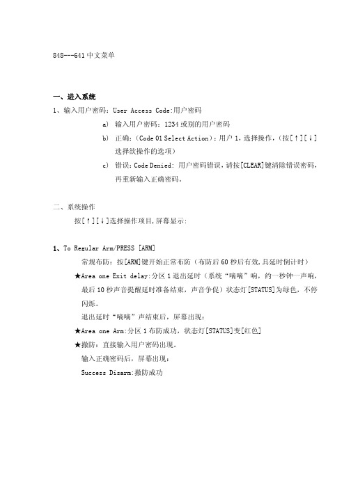
848---641中文菜单一、进入系统1、输入用户密码:User Access Code:用户密码a) 输入用户密码:1234或别的用户密码b) 正确:(Code 01 Select Action):用户1,选择操作,(按[↑][↓]选择欲操作的选项)c) 错误:Code Denied: 用户密码错误,请按[CLEAR]键清除错误密码,再重新输入正确密码。
二、系统操作按[↑][↓]选择操作项目,屏幕显示:1、To Regular Arm/PRESS [ARM]常规布防:按[ARM]键开始正常布防(布防后60秒后有效,具延时倒计时) ★Area one Exit delay:分区1退出延时(系统“嘀嘀”响,约一秒钟一声响,最后10秒声音提醒延时准备结束,声音争促)状态灯[STATUS]为绿色,不停闪烁。
退出延时“嘀嘀”声结束后,屏幕出现:★Area one Arm:分区1布防成功,状态灯[STATUS]变[红色]★撤防:直接输入用户密码出现。
输入正确密码后,屏幕出现:Success Disarm:撤防成功2、To Stay arm/ PRESS [STAY]:留守布防:按[STAY]键开始留守布防(布防后60秒后有效,无其它提示)其它提示请参考(1:正常布防)。
◆留守布防:只对家里门、窗户等区域部分布防,人可以在屋内正常活动,但却可防止有人从门、窗户、阳台等区域闯入家里。
3、To Instant arm/ PRESS [5]: 立即布防,按[5]键立即布防4、To Force arm/ PRESS [FORCE]:强制布防:按[FORCE]键开始强制布防5、To Disarm/ PRESS [DISARM]:撤防:按[DISARM]键对系统撤防6、Alarm Memory/[MEM] To View:系统报警记录:按[MEM]查看报警记录★Alarm in: 表示哪个防区曾经报警。
★Memory Empty:记录为空,说明系统没有报警记录。

Grand Rapids, Michigan, U.S.A. 49504-5298USER’S OPERATING AND INSTRUCTION MANUALMODEL 641DOUGH ROLLER0641S20000-CV641 DOUGH ROLLERINDEXSection Description Document No.Page No.SAFETY INSTRUCTIONS -------------------------------------- 0641S20003 --------------------------- 1-1DESCRIPTION/SPECIFICATIONS --------------------------- 0641S20004---------------------------- 2-1Description2-1 --------------------------------------------------------------------------------------------------2-1Specifications-----------------------------------------------------------------------------------------------INSTALLATION INSTRUCTIONS ---------------------------- 0641S20005 --------------------------- 3-1 Dough Roller Installation ---------------------------------------------------------------------------------3-1OPERATING INSTRUCTIONS -------------------------------- 0641S20006 --------------------------- 4-1TROUBLESHOOTING ------------------------------------------- 0641S20007 --------------------------- 5-1 The Dough Roller Will Not Start (Motor is Not Humming) --------------------------------------- 5-1The Dough Roller Will Not Start (Motor is Humming) -------------------------------------------- 5-1Lines or Marks in Finished Crust ---------------------------------------------------------------------- 5-2The Dough is Not Feeding ------------------------------------------------------------------------------ 5-2The Dough is Sticking to Rollers -----------------------------------------------------------------------5-3MAINTENANCE --------------------------------------------------- 0641S20008 --------------------------- 6-1 Cleaning ----------------------------------------------------------------------------------------------------- 6-1Removing Scrapers -------------------------------------------------------------------------------------- 6-1General Notes on Disassembly ----------------------------------------------------------------------- 6-2 -------------------------------------------------------------------------------------------------- 6-2LubricationService ------------------------------------------------------------------------------------------------------- 6-2RECOMMENDED SPARE PARTS -------------------------- 0641S20009 --------------------------- 7-1REPLACEMENT PARTS SECTIONMAIN FRAME ------------------------------------------------------ 0641S20010 --------------------------- 8-1Drawing8-1 ------------------------------------------------------------------------------------------------- Parts List ----------------------------------------------------------------------------------------------- 8-2ROLLERS ---------------------------------------------------------- 0641S20011 --------------------------- 9-19-1 Drawing------------------------------------------------------------------------------------------------- Parts List ----------------------------------------------------------------------------------------------- 9-2TABLES ------------------------------------------------------------- 0641S20012 ---------------------------10-1 ------------------------------------------------------------------------------------------------10-1DrawingParts List -----------------------------------------------------------------------------------------------10-2COVERS ------------------------------------------------------------ 0641S20013 ---------------------------11-1 ------------------------------------------------------------------------------------------------11-1DrawingParts List -----------------------------------------------------------------------------------------------11-2ContinuedINDEX (Continued)Section Description Document No.Page No. DRIVE --------------------------------------------------------------- 0641S20014 ---------------------------12-1 Drawing------------------------------------------------------------------------------------------------12-1 Parts List -----------------------------------------------------------------------------------------------12-2ELECTRICAL PARTS ------------------------------------------- 0641S20015 ---------------------------13-1 ------------------------------------------------------------------------------------------------13-1 DrawingParts List -----------------------------------------------------------------------------------------------13-2OPTIONAL STAND ---------------------------------------------- 0641S20016 ---------------------------14-1 ------------------------------------------------------------------------------------------------14-1 DrawingParts List -----------------------------------------------------------------------------------------------14-2 WIRING DIAGRAMS -------------------------------------------- 0641S20017 ---------------------------15-1 WARRANTY ------------------------------------------------------- GEN 040225WARRANTY PROCEDURE------------------------------------ GEN 040226RETURNED PARTS POLICY --------------------------------- GEN 040227641 DOUGH ROLLERSAFETY INSTRUCTIONSWARNINGVARIOUS SAFETY DEVICES AND METHODS OF GUARDING HAVE BEEN PROVIDED ON THIS MACHINE. IT IS ESSENTIAL HOWEVER THAT THE MACHINE OPERATORS AND MAINTENANCE PERSONNEL OBSERVE THE FOLLOWING SAFETY PRECAUTIONS. IMPROPER INSTALLATION, MAINTENANCE, OR OPERATION OF THIS EQUIPMENT COULD CAUSE SERIOUS INJURY OR DEATH.1. Read this manual before attempting to operate your machine. Never allow anuntrained person to operate or service this machine.2. Connect the machine to a properly grounded electrical supply that matches therequirements shown on the electrical specification plate and follow all specifications of local electrical codes.3. Disconnect and lock-out the machine from the power supply before cleaning orservicing.4. Check and secure all guards before starting the machine.5. Observe all caution and warning labels affixed to the machine.6. Use only proper replacement parts.7. Do not wear loose fitting clothing or loose hair when working near this machine.Shirt tails should be tucked in.8. Wear proper, personal, protective, safety equipment.9. Keep Hands away from the moving parts of this machine while it is in operation.10. In addition to these general safety instructions, please follow the more specific safetyinstructions in the rest of this operating instruction manual.WARNINGDO NOT USE FOR OTHER THAN ORIGINALLY INTENDED PURPOSE.641 DOUGH ROLLERDESCRIPTION/SPECIFICATIONSDescriptionThe Oliver Model 641 Dough Roller is engineered to exacting standards. It’s designed to provide maximum performance in minimal space. The machine is easy to operate, crusts of uniform thickness are made quickly and easily.Parts to be cleaned are quickly removed without the use of tools.Available in 14”, 17” and 21” capacities.SpecificationsSpace Requirements:Model 641 (All Dimensions are Approximate)ContinuedDESCRIPTION/SPECIFICATIONS (Continued)NOTEStandard Electrical Options: (Others consult factory).½ HP, 1 phase, 60 hz, 115VAC, 7 Amps.½ HP, 1 phase, 60 hz, 230VAC, 3.5 Amps.½ HP, 1 phase, 50 hz, 220VAC, 3.5 Amps.Standard Product Width Capacity14”, 17”, & 21”Shipping Weight14”: 212 lbs. (95 kg) (approximate)17”: 227 lbs. (102 kg) (approximate)21”: 257 lbs. (116 kg) (approximate)HeightBench Top: 21” (533 mm), (all widths) (approximate)On Optional Stand: 54” (1372 mm), (all widths) (approximate) Bench Space(All Dimensions are Approximate)14”: 30” (762 mm) X 33” (838 mm)17”: 33” (838 mm) X 33” (838 mm)21”: 37” (940 mm) X 33” (838 mm)Options33” High Metal Stand with 3” Casters.Above specifications subject to change without notice.641 DOUGH ROLLERINSTALLATION INSTRUCTIONSDough Roller Installation:Before starting the Installation process make sure you observe the following three caution notes.CAUTIONTHE DOUGH ROLLER IS HEAVY, USE PROPER TECHNIQUE WHEN LIFTING.KEEP BACK STRAIGHT, KNEES BENT, AND LIFT WITH LEGS.USE GLOVES TO PROTECT HANDS.CAUTIONNEVER LIFT THE DOUGH ROLLER BY ITS COVERS OR GUARDS.CAUTIONBEFORE PLACING THE DOUGH ROLLER ON THE TABLE OR COUNTER MAKE SURE THAT IT CAN SUPPORT THE DOUGH ROLLER’S WEIGHT WHICH ISAPPROX. 260 POUNDS (21”).Bench MountedSelect a location for your dough roller which has a substantial mounting surface, (see the caution note above), and which has electrical service compatible with the load the machine will place on it as indicated on the electrical data plate of the machine.Position the machine while it is still in its packaging as close as possible to the desired end location. Expose the machine by removing the outer packaging. Remove any straps or fasteners securing machine to crate. Using at least two people, (one in the front and one at the back of the machine), lift the dough roller from the resting surface of the packaging and set the machine onto the counter or table as close as possible to the desired end location. The machine must be sealed to the counter using the included neoprene rubber under machine edges. Plastic Hole plugs are included to close any unused holes in machine base.ContinuedINSTALLATION INSTRUCTIONS (Continued)Optional Stand MountedNote: One bottom guard bolt will have to be removed to mount machine to stand.Select a location for your dough roller which has a level surface, and which has electrical service compatible with the load the machine will place on it as indicated on the electrical data plate of the machine.Position the machine while it is still in its packaging as close as possible to the desired end location. Expose the machine and stand by removing the outer packaging. Remove any straps or fasteners securing machine and stand to crate. Machine will only go on the stand one way. Using at least two people, (one in the front and one at the back of the machine), lift the dough roller from the resting surface of the packaging and set the machine onto the stand. Secure to stand using the provided fasteners.(see page 14-1)For all Machines1. Be sure machine is clean and dry.2. Make sure power switch is in “Off” position.3. Check machine nameplate for correct voltage and frequency.4. Connect machine to a power source that matches nameplate requirements.5. Switch power “On” and check for proper operation of the machine.641 DOUGH ROLLEROPERATING INSTRUCTIONSWARNINGALWAYS USE CARE WHENEVER WORKING NEAR THE ROLLERS.KEEP HANDS CLEAR OF DOUGH CHUTE.Machine Preparation1. Make sure the dough chute and trays are dry.2. Dust the transfer tray (Item 200, page 10-1) with flour, Leave a little extra flour in the tray to dust the bottom side of the dough before it is sent through the second set of rollers.3. Make your initial setting of the roller adjustment levers. Loosen knob, move handle, then tighten knob. Dial numbers are for reference only.Dough Preparation1. Size and shape of the dough ball affects size and shape of the finished crust. For round pies make a dough piece a fat sausage shape and flatten slightly.2. Dust the dough pieces with flour before putting them in the machine.Making a Crust1. Place the dough piece in the top hopper chute (Item 206, page 10-1) end first.2. When the dough piece comes out in the transfer tray it should be a little longer than the diameter of the pie.3. Dust the top of the dough with flour. There should be sufficient flour in the transfer tray to dust the bottom of the dough.4. Turn the dough piece a quarter of a turn in the transfer tray and slide it sideways into the second pass rollers.WARNINGNEVER PUSH THE DOUGH WITH THE TIPS OF YOUR FINGERS.5. The second pass rollers should produce a crust of the proper thickness and about round in shape. If the crust is too thin, open the lower rollers. If the crust is to thick, close the lower rollers. If the thickness is right but the crust is too short, make the initial dough piece bigger and open the upper rollers. If it is too long, make the initial dough piece smaller and close the upper rollers. When you get the results you want, it is a good idea to write down the setting numbers if the adjustment levers for future reference.641 DOUGH ROLLERTROUBLESHOOTINGWARNINGALWAYS DISCONNECT THE DOUGH ROLLER FROM THE POWER SUPPLYBEFORE ATTEMPTING ANY TYPE OF MAINTENANCE TASK, INCLUDINGTROUBLESHOOTING.The Dough Roller Will Not Start (Motor Is Not Humming)•The machine is not plugged in.•There is no power at the outlet. (Check by plugging in a small working appliance, like a lamp. Check to see if a circuit breaker has tripped. If the circuit breaker has not tripped and the circuit is still not working have a qualified electrician check the circuit.)•The thermal overload on dough roller power switch has tripped – turn machine off, allow to cool then push switch further “Off” to reset.•The problem is somewhere else in the electrical system of the machine. (Have a qualified electrician find and repair the problem.)The Dough Roller Will Not Start (Motor Is Humming)CAUTIONDO NOT ALLOW THE MOTOR TO HUM WITHOUT STARTING.OVERHEATING CAN PERMANENTLY DAMAGE THE MOTOR.NOTEA SPECIAL NON-VENTILATED MOTOR MUST BE USED WITH THIS DOUGHROLLER.•The drive system is binding. (Have a qualified service agent check for defective bearings or other restrictions to free movement.)•There is mechanical interference between other parts of the Dough Roller. (Have a qualified service agent evaluate the machine for adjustment or replacement ofdefective parts.)ContinuedTROUBLESHOOTING (Continued)•Broken belt or chain. (Have a qualified service agent evaluate the machine for adjustment or replacement of defective parts.)•The motor has failed. (Have it checked by a qualified electrician.)Lines or Marks in Finished Crust•The rollers need to be cleaned. (see Maintenance section of this manual)The Dough is Not Feeding•Too much flour on dough surface. Dust dough with less flour.•Dough piece is too thin for current roller setting.The Dough is Sticking to Rollers•Dough needs more flour on surface. Dust dough with more flour.•The rollers need to be cleaned. (see Maintenance section of this manual) •Missing or improperly installed scrapers. (see Maintenance section of this manual)641 DOUGH ROLLERMAINTENANCEWARNINGALWAYS UNPLUG THE DOUGH ROLLER BEFORE PERFORMINGANY TYPE OF MAINTENANCE TASK.CleaningThe machine should be cleaned daily, more often during heavy use. Use a damp, soft cloth on the fixed parts of the machine. Trays and scrapers may be taken to sink for cleaning.Removing ScrapersRemove the scrapers and slides as follows. Reverse the procedures to install them.1. Long top scraper and tip.a. Grasp the scraper with both hands.b. Press down to compress springs and release the retainer.c. Shift sideways toward the belt guard.d. Swing the end opposite the guard away from machine.e. Slide the scraper sideways away from the guard to free the secondend. When reinstalling the scraper make sure the long slot is toward thebelt guard.2. Long bottom scraper slide and tip.(first remove the long top scraper as described above)a. Look under the slide before you attempt to remove it. Note the angleson the bottom of the slide that hold it in place.b. To remove the slide grasp it with both hands, one on either side, andlift sharply to both compress the springs and lift the angles clear of thepins that support and retain the tray.c. Pull the tray toward you to remove it from the machine.3. Short top scraper and tip.a. Grasp the scraper with both hands.b. Press down to compress springs and release the retainer.c. Shift the scraper toward the center of the machine.d. Swing the end closest to belt guard of the scraper away from themachine.e. Slide the scraper sideways away from the center of the machine toremove it. When reinstalling the scraper make sure the long slot istoward the center of the machine.ContinuedMAINTENANCE (Continued)Removing Scrapers (Continued)4. Short bottom scraper slide and tip.(first remove the long top scraper as described above)a. Grasp the scraper with both hands.b. Lift up sharply to compress the springs and release the retainer.At the same time, raise the end of the slide so it will clear the lip of thetransfer tray.c. Swing the inboard end of the scraper which is furthest from the beltguard toward the roller.d. Slide the scraper sideways toward the belt guard until the end furthestfrom the belt guard clears the stud assembly.e. Swing the end furthest from the belt guard away from the roller until thescraper is in front of the stud assembly.f. Slide the scraper toward the center of the machine to remove it.g. When reinstalling the scraper you must lift the retainer plate on the studassembly furthest from the belt guard so that the hooked end of thescraper can slide under the plate and around the stud.General Notes on Disassembly1. DO NOT LOOSEN THE ACORN NUTS OR THE STUD ASSEMBLIES! Theyare factory set to assure proper contact of the scraper tip on the roller.2. The white nylon scraper tips are easily removed from the scraper bar frocleaning by sliding them off with your fingers.3. WHEN REINSTALLING THE WHITE SCRAPER TIP, MAKE SURE THESMOOTH SIDE OF THE TIP (NOT THE STEPPED SIDE) WILL BE TOWARDTHE DOUGH DURING OPERATION!Lubrication1. All bearings are permanently lubricated and do not require further lubrication.2. Add a drop or two of medium weight food safe oil to the oil cup on the chainidler arm every 200 hours. The cup is located above the shaft of the main drivepulley and slightly under the dough hopper casting.ServiceIf you properly care for your Oliver Products Company Dough Roller, it will give you long, trouble free service. If replacement parts are required, order them from the factory. Refer to the Replacement Parts section of this manual for the item’s specific part number.641 DOUGH ROLLERRECOMMENDED SPARE PARTSPART NUMBER PART DESCRIPTION NO. REQ’D0641-1201-001 Tip-Scraper 7” roller 20641-1201-002 Tip-Scraper (14” machine) 20641-1201-003 Tip-Scraper (17” machine) 20641-1201-004 Tip-Scraper (21” machine) 25601-1238 Belt-V (5L580) 16301-3609* Motor-1/2 HP, 1-60-115/230 15709-1137 Starter-Manual (Power Switch and Enclosure) 15708-2430 Heater-Overload (115 VAC) 15708-2423 Heater-Overload (220/230 VAC) 14560-2508-1109 Knob with stud (1/4-20) 2(3/8-16) 2 5911-7033 Knob(1/2-13) 2 5911-7046 KnobSprocket 1 0641-1017 MainDriveassembly 1 0641-0188 Chain*For Other Electrics Contact the FactoryFor Service Parts Call Oliver Products @ 800-253-3893MAIN FRAMEMAIN FRAME PARTS LISTITEM NO PART DESCRIPTION PART NUMBER 001 Base RH (14” machine) 0641-1004-0011 001 Base RH (17” machine) 0641-1275-0011 001 Base RH (21” machine) 0641-1048-0011 002 Plate-Side Drive 0641-1209004 Plate-Side Adjustment 0641-1210 005 Tie Bar (square) (14” machine) 0641-1011-001 005 Tie Bar (square) (17” machine) 0641-1011-002 005 Tie Bar (square) (21” machine) 0641-1011-003 007 Tie Bar (round) (14” machine) 0641-1012-001 007 Tie Bar (round) (17” machine) 0641-1012-002 007 Tie Bar (round) (21” machine) 0641-1012-003 008 Motor Mounting Plate (14” machine) 0641-1203-001 008 Motor Mounting Plate (17” & 21” machines) 0641-1203-002 011 Dial-Top 0641-1100014 Pin-Spring 5835-6789015 Dial-Bottom 0641-1101 FOR SERVICE PARTS CALL OLIVER PRODUCTS @ 800-253-3893ROLLERSROLLERS PARTS LISTITEM NO PART DESCRIPTION PART NUMBER 100 Roller 7” 0641-1240-101101 Sprocket-Drive Roller 4615-4120-3631 103 Bearing 5250-0207 104 Shaft-Top Roll (14” machine) 0641-1016-001 104 Shaft-Top Roll (17” machine) 0641-1016-002 104 Shaft-Top Roll (21” machine) 0641-1016-003105 Eccentric-Drive Side 0641-1051106 Eccentric-Adjustment Side 0641-1052108 Set Collar 5806-7058110 Handle-Adjustment 0641-1105111 Screw-Adjustment 0641-0012-008 112 Flat Washer ½ STST 5851-9308113 Knob (1/2-13) 5911-7046 115 Roller (14” machine) 0641-1240-102 115 Roller (17” machine) 0641-1240-103 115 Roller (21” machine) 0641-1240-104 116 Shaft-Center Roller (14” machine) 0641-1013-001 116 Shaft-Center Roller (17” machine) 0641-1013-002 116 Shaft-Center Roller (21” machine) 0641-1013-003Continued FOR SERVICE PARTS CALL OLIVER PRODUCTS @ 800-253-3893ROLLERS PARTS LIST (Continued)ITEM NO PART DESCRIPTION PART NUMBER 117 Spacer-Adjustment Side 0641-1074118 Spacer-Drive Side 0641-1075 121 Shaft-Finish Roller (14” machine) 0641-1014-001 121 Shaft-Finish Roller (17” machine) 0641-1014-002 121 Shaft-Finish Roller (21” machine) 0641-1014-003 122 Handle-Adjustment Lower 0641-0012FOR SERVICE PARTS CALL OLIVER PRODUCTS @ 800-253-3893TABLESTABLES PARTS LISTITEM NO PART DESCRIPTION PART NUMBER 200 Tray Assembly (14” machine) 0641-1302200 Tray Assembly (17” machine) 0641-1104-001 200 Tray Assembly (21” machine) 0641-1104-002 201 Bracket-Support (14” machine) 0641-1084201 Bracket-Support (17” & 21” machine) 0641-1106206 Hopper-Dough Chute 0641-1091 208 Scraper Slide Assembly (14” machine) 0641-1143-001 208 Scraper Slide Assembly (17” machine) 0641-1143-002 208 Scraper Slide Assembly (21” machine) 0641-1143-003 209 Scraper Tip (14” machine) 0641-1201-002 209 Scraper Tip (17” machine) 0641-1201-003 209 Scraper Tip (21” machine) 0641-1201-004 210 Scraper Body RH (14” machine) 0641-1141-001 210 Scraper Body RH (17” machine) 0641-1141-002 210 Scraper Body RH (21” machine) 0641-1141-003211 Post-Scraper 0641-1312214 Spring-RH 4605-1000-0016 215 Lifter-Spring RH 0641-1053-0001 216 Washer-U 5851-8137Continued FOR SERVICE PARTS CALL OLIVER PRODUCTS @ 800-253-3893Rev. 8/27/05TABLES PARTS LIST (Continued)ITEM NO PART DESCRIPTION PART NUMBER 217 Washer 1-3/8 O.D. 4655-0314-1001 218 Locknut & Washer Assembly 0641-1061219 Retainer-Scraper 0641-1062 220 Scraper Slide Assembly 7” 0641-1147221 Scraper Tip 7” 0641-1201-001 222 Scraper Assembly RH 0641-1144-0001 223 Support Scraper Slide 0641-1058224 Retainer-Spring 0641-1034225 Retainer-Spring Upper 0641-1034-001 226 Spring 15/16 x 2-1/16 4605-1000-0017 228 Support Scraper Slide 0641-1056229 Link-Strap 0641-1059 232 Support Tray and Slide 0641-1055FOR SERVICE PARTS CALL OLIVER PRODUCTS @ 800-253-3893THIS PAGE WAS INTENTIONALLYLEFT BLANK.COVERSREV. 11/10/05COVERS PARTS LISTITEM NO PART DESCRIPTION PART NUMBER 300 Guard Backing Plate 0641-0022-0001 304 Belt Guard 0641-0023-0011 307 Center Roller Guard (14” machine) 0641-0024-0011 307 Center Roller Guard (17” machine) 0641-0024-0001 307 Center Roller Guard (21” machine) 0641-0024-0021 308 Guard- Roller End 0641-0033-0001 309 Rear Guard (14” machine) 0641-0032-0011 309 Rear Guard (17” machine) 0641-0032-0001 309 Rear Guard (21” machine) 0641-0032-0021 310 Knob with Stud (1/4-20) 4560-2508-1109 311 Knob (3/8-16) 5911-7033312 Outfeed Guard 0641-0028-0001 314 Bottom Guard (14” machine) 0641-0027-001 314 Bottom Guard (17” machine) 0641-0027314 Bottom Guard (21” machine) 0641-0027-002317 Chain Guard 0641-0026-0001REV. 11/10/05FOR SERVICE PARTS CALL OLIVER PRODUCTS @ 800-253-3893DRIVEDRIVE PARTS LISTITEM NO PART DESCRIPTION PART NUMBER 400 Bracket-Drive Sprocket 0641-1025401 Shim-Bracket 0641-1353403 Bearing 5250-0207404 Main Drive Sprocket 0641-1017 405 Spacer-Main Drive Sprocket 0641-1079406 Sheave 5L 5615-1629408 Arm-Chain Takeup RH 0641-1028-0001 409 Retaining Ring 5840-1357411 Idler Roller 0641-1029412 Stud-Shaft Idler 0641-1031 FOR SERVICE PARTS CALL OLIVER PRODUCTS @ 800-253-3893ELECTRICAL PARTSRev. 8/27/05ELECTRICAL PARTS LISTITEM NO PART DESCRIPTION PART NUMBER 800* Motor-1/2 HP, 1-60-115/230 6301-3609801 Sheave 5615-1500 802 Belt-V (5L580) (Not shown) 5601-1238803 Strain relief 90 deg. 5770-4806807 Starter-Manual 5709-1137 808* Heater-Overload (115 VAC) 5708-2434808* Heater-Overload (230 VAC) 5708-2427811 Strain Relief 5765-1082*For Other Electrics Contact the FactoryFOR SERVICE PARTS CALL OLIVER PRODUCTS @ 800-253-3893Rev. 3/23/07OPTIONAL STANDOPTIONAL STAND PARTS LISTITEM NO PART DESCRIPTION PART NUMBER 901 Stand (14” machine) 0641-1044-101 901 Stand (17” machine) 0641-1044-102 901 Stand (21” machine) 0641-1044-103 902 Bolt 3/8 x 2-1/2 5843-1060903 Nut 3/8 5832-0522904 Socket-Caster 5902-2601905 Caster 2-1/2” 5902-2348 FOR SERVICE PARTS CALL OLIVER PRODUCTS @ 800-253-3893WARRANTYPARTSOliver Packaging & Equipment Company (Oliver) warrants that if any part of the equipment (other than a part not manufactured by Oliver) proves to be defective (as defined below) within one year after shipment, and if Buyer returns the defective part to Oliver within one year, Freight Prepaid to Oliver’s plant in Grand Rapids, MI, then Oliver, shall, at Oliver’s option, either repair or replace the defective part, at Oliver’s expense.LABOROliver further warrants that equipment properly installed in accordance with our special instructions, which proves to be defective in material or workmanship under normal use within one (1) year from installation or one (1) year and three (3) months from actual shipment date, whichever date comes first, will be repaired by Oliver or an Oliver Authorized Service Dealer, in accordance with Oliver’s published Service Schedule.For purposes of this warranty, a defective part or defective equipment is a part or equipment which is found by Oliver to have been defective in materials workmanship, if the defect materially impairs the value of the equipment to Buyer. Oliver has no obligation as to parts or components not manufactured by Oliver, but Oliver assigns to Buyer any warranties made to Oliver by the manufacturer thereof.This warranty does not apply to:1. Damage caused by shipping or accident.2. Damage resulting from improper installation or alteration.3. Equipment misused, abused, altered, not maintained on a regular basis, operated carelessly, orused in abnormal conditions.4. Equipment used in conjunction with products of other manufacturers unless such use is approvedby Oliver Products in writing.5. Periodic maintenance of equipment, including but not limited to lubrication, replacement of wearitems, and other adjustments required due to installation, set up, or normal wear.6. Losses or damage resulting from malfunction.The foregoing warranty is in lieu of all other warranties expressed or implied AND OLIVER MAKES NO WARRANTY OF MERCHANTABILITY OR FITNESS FOR PURPOSE REGARDING THE EQUIPMENT COVERED BY THIS WARRANTY. Oliver neither assumes nor authorizes any person to assume for it any other obligations or liability in connection with said equipment. OLIVER SHALL NOT BE LIABLE FOR LOSS OF TIME, INCONVENIENCE, COMMERCIAL LOSS, INCIDENTAL OR CONSEQUENTIAL DAMAGES.WARRANTY PROCEDURE1. If a problem should occur, either the dealer or the end user must contact the Parts andService Department and explain the problem.2. The Parts and Service Manager will determine if the warranty will apply to this particularproblem.3. If the Parts and Service Manager approves, a Work Authorization Number will begenerated, and the appropriate service agency will perform the service.4. The service dealer will then complete an invoice and send it to the Parts and ServiceDepartment at Oliver Products Company.5. The Parts and Service Manager of Oliver Packaging and Equipment Company willreview the invoice and returned parts, if applicable, and approve for payment.。
风速仪641中文说明书
风速仪641中文说明书1、概述风速仪是一种精密测量风速的仪器,可以用于风速值、风量和噪声测量,以及可在气象、工业、农业等领域使用。
风速仪641由高分辨率的风速传感器、液晶显示器、温度和湿度调节装置等组成。
2、工作原理本仪器采用热电阻测量原理,即在一定的温升下,当被测的气体通过一定直径的管状传热元件时,由于热传导而使被测气体温度升高。
在不同的工作温度下,被测气体压力不同;由于不同温度下被测气体压力是相似的,所以,将两个工作状态分别转换为压力值。
3、测量范围和精度:在测量范围内,仪器可测量任何浓度或任何密度的气体,不受气压变化和空气质量变化的影响而产生偏差。
本。
PSL 641K数字式进线合环保护装置技术说明书使用说明书V1.60国电南京自动化股份有限公司* 本说明书可能会被修改,请注意最新版本资料* 由国电南自技术部监制第一部分技术说明书目次1装置简介 (2)2技术参数 (5)2.1额定参数 (5)2.2主要技术性能 (5)2.3绝缘性能 (6)2.4电磁兼容性能 (6)2.5机械性能 (7)2.6环境条件 (8)3装置硬件 (9)3.1机箱结构 (9)3.2交流模件 (9)3.3CPU模件 (9)3.4电源模件 (12)3.5逻辑及跳闸模件 (12)3.6人机对话模件 (13)4保护原理 (14)4.1过电流元件 (14)4.2零序过电流元件 (14)4.3TV断线检测 (15)4.4小电流接地选线 (15)4.5数据记录 (15)5与变电站自动化系统配合 (16)6定值及整定说明 (17)6.1PSL641K数字式进线合环保护装置整定值清单及说明 (17)6.2PSL641K数字式进线合环保护装置软压板清单及说明 (18)·声明·声明感谢您购买了国电南京自动化股份有限公司的数字式保护及自动化产品。
国电南京自动化股份有限公司的所有PS系列数字式保护及自动化产品符合严格的技术标准,经得起恶劣的现场工作环境的考验,综合技术指针处于国内领先水平。
本公司拥有一大批具有丰富的数字式保护及自动化产品开发经验的科技人才,承诺对用户常年24小时的技术支持,您尽可以信赖国电南京自动化股份有限公司的产品。
PS系列产品采用完全汉化的显示技术,人机界面友好,使您免除查找说明书操作的烦恼。
每款产品均配置了基于PC机调试接口的接口,结合本公司提供的Psview调试软件包,大大改善了现场调试手段。
PS 640系列产品采用防水、防尘、抗振动设计,适合安装于开关柜等环境条件较为恶劣的现场运行。
机箱面板采用先进的工业美学设计,使用方便,倍感亲切。
PS 640系列数字式保护及自动化产品具有如下特点:◆大资源、高起点●摩托罗拉32位单片机技术,使产品的稳定性和运算速度得到保证●保护采用14位的A/D转换器、可选配的专用测量模块其A/D转换精度更是高达24位,各项测量指标轻松达到●配置以大容量的RAM和Flash Memory,可记录8至50个录波报告,记录的事件数不少于40次。
Ⅱ. DFD641割片机菜单介绍0.0主目录介绍:F1 用于调用机种进行全自动切割动作F2 用于多机种连续的全自动切割动作F3 对晶圆切割全过程进行手动操作F4 用于机种型号的编辑F5 用于对切割刀片的资料维护F6 对机器一般效能参数的维护F7 用于机器机械部分参数及机构的维护F8 用于检查机器各设备状况及显示各记录机器当前作业日期当前作业的型号参数资料( 在4.0画面调用型号参数后将显示)机器系统自带资料,非设定项目3.0 手动操作:对晶圆切割全过程进行手动操作F1 将晶圆从cassete内夹出并运送到工作盘上F2 收集晶圆图像资料,见3.2.1画面F3 同一片晶圆上有不同型号晶粒时使用F4 对晶圆进行自动切割动作(CH1和CH2连续切割)F5 对晶圆进行半自动切割动作,见3.5画面(既先切割CH1,手动θ调整即晶圆旋转90°后,影像教读,再切CH2) F6 将工作台面上的晶圆送到清洗盘上F7 对晶圆进行清洗动作F8 将清洗完的晶圆送入cassete内F9 对外型进行辨识F10 执行影像教读(3.2)后,做一次晶圆辩识载物箱内cassete的数量晶圆在cassete的第几格进料当前作业的型号参数资料( 在4.0画面调用型号参数后将显示)3.2.1 影像教读:收集晶圆图像资料F1 对晶圆进行重新辩识F4 视窗大小调节, 见视窗调节画面(先低倍用小窗对晶圆调,再高倍用大窗对晶粒CH1/CH2调)F5 调节晶圆的水平度;F6 自动对晶圆进行影像辩识F7 照明灯光亮度调节,见调光画面F8 调节图象的清晰度, 见对焦画面F9 自动对晶圆进行辩识F10 显微镜低倍率(LO) /高倍率(HI)切换视窗调节画面F1 视窗X方向尺寸减5 F6 视窗Y方向尺寸减5F2 视窗X方向尺寸减1 F7 视窗Y方向尺寸减1F3 视窗X方向尺寸加1 F8 视窗Y方向尺寸加1F4 视窗X方向尺寸加5 F9 视窗Y方向尺寸加5F10 以系统内部设定视窗大小为准θ角校正画面先在晶片上找一特定点按F5(θ角校正),再调节视窗位置使其在晶片的同一位置,再按F5(θ角校正)调整;反复几次操作后,直到视窗在各处晶片位置都一致且TV下方显示“完成θ角调整”调光画面F1 直射光强度数值减5 F6 斜射光强度数值减5F2 直射光强度数值减1 F7 斜射光强度数值减1F3 直射光强度数值加1 F8 斜射光强度数值加1F4 直射光强度数值加5 F9 斜射光强度数值加5F5 系统自动根据影像调节光源强度F10 以系统内部设定光源强度为准对焦画面F2 摄像头手动上升对焦F3 校准参数对焦F4 大行程对焦F5摄像头位置归零后在重新自动调焦F7 摄像头手动下降对焦F8 型号参数对焦F9 小行程对焦3.5 半自动切割画面F1 切割向Y+ 方向调节F6 切割向Y- 方向调节F2 对切割的深度进行调节F7 更改进刀速度F8 到“4.1.2型号参数”画面F4 手动对晶圆进行校准,见手动调焦画面F9 对晶圆进行预切动作F5 割刀向Y+ 方向切割F10 割刀向Y- 方向切割右边数据是切割时的作业参数手动调焦F7 对照明灯光进行调节F8 显微镜对晶圆进行调焦使图像清晰F4 将基准线宽度调窄F9 将基准线宽度调宽F5 对晶圆进行θ角校正F10 显微镜低倍率(LO) /高倍率(HI)切换4.0 型号目录画面F1 上页F6 下页F2 对型号资料进行拷贝F7 移动光标到所需要处F3 将型号参数移动到另一子目录F8 添加子目录F4 更改型号名称的参数号F9 删除子目录F5 删除该型号参数F10 直接选用光标所指的型号名称4.1.2型号参数画面(选择一项切割参数后,按ENTER键进入4.1.2画面)F1 对光标处的参数进行选择F6 至“4.1.6程序控制表”画面(用来进行单位互换) F7 预切割教程F3 至“4.1.3校准参数”画面F8 至“4.1.8刀痕检查参数”画面F4 至“4.1.4洗净搬送参数”画面F9 特殊仕样F5 多重尺寸F10 测量晶片大小(提示:只需要设定旋转轴转速、晶片厚度、进刀速度、圆形切割尺寸、晶粒尺寸,其他都是固定不变)4.1.3校准参数:设定校准参数,以利于“3.2 影像教读”注意事项①跳格检查Y方向:10晶粒容许值:0.001mm②粗调θ值50以上③CH1/CH2θ值80以上。
EVO48操作说明书(标配641键盘)
常规布防:【密码】+【ARM】+ 如果没分区,则系统直接布防
如果分区,则选择分区号,如果全区布防则按【0】
强制布防:【密码】+【FORCE】+ 如果没分区,则系统直接布防
如果分区,则选择分区号,如果全区布防则按【0】注意:强制布防时,防区必须有强制防区的属性(默认无效,启动:防区选项【4】)
旁路布防:【密码】+【BYP】+【防区号】+液晶显示【防区号】Pypassed 防区旁路成功如果还需旁路其他防区,在【CLEAR】+【防区号】,操作结束后,按【ENTER】退出注意:被旁路的防区必须有被旁路的属性(默认有效)
留守布防:【密码】+【STAY】+如果没分区,则系统直接布防
如果分区,则选择分区号,如果全区布防则按【0】注意:留守布防时,只有被设为留守防区的防区处于撤防状态
系统撤防:【密码】+【DISARM】+如果没分区,则系统直接撤防
如果没区,则选择分区号,如果全区撤防则按【0】
警情查询:当屏幕上显示Trouble(s) Prss 【MEN】表示有报警信息
查看只需按一下【MEN】键,通过俺“▲”“▼”翻页来查询不同的报警防区
故障查询:当屏幕上显示Trouble(s) Prss 【TBL】表示有报警信息
查看只需按一下【TBL】键,通过俺“▲”“▼”翻页来查询不同的故障
修改时间:
【密码】+【TBL】+【8】+【__:_ _】(24小时制时间)+【Y=XXXX M=XX D=XX】(日期)
密码修改/添加:
【密码】+【0】+【ACC】+【XXX】(三位用户编码)+【XXXX】(4位新密码)+【ENTER】+【CLEAR】
注意:系统常规布防时,必须等待键盘上的【STATUS】绿灯亮,表示系统所以防区全部准备好,可以常规布防。
制作人:孙馨垚
备注:如果在文本中发现问题,以及漏洞,请及时联系我,以便第一时间修正。