岩土文献
- 格式:pdf
- 大小:2.75 MB
- 文档页数:17

岩土工程论文岩土工程论文随着我国社会经济的发展,人们对建筑的需求逐渐升高。
作为建筑工程的基础项目,岩石工程的质量对建筑工程的总体质量有着重大的影响。
下文是关于基建项目中的岩土工程勘察探析论文,欢迎借鉴!摘要:当前,我国的基本建设事业正处在高速发展的阶段,为了确保建设质量,我们必须要做好对应的岩土工程勘察,因为在绝大多数的基本建设中,岩土工程勘察都是最为重要的技术性环节。
通过全面、准确的岩土工程勘察,才能为项目的决策、设计和施工提供科学的参考依据,保证工程的可行性和工程建设的质量。
所以我们必须要加强相关的研究、探讨与实践,做好岩土工程勘察工作,为基本建设质量提供保障。
本文基于作者自身的实际工作与学习经验,主要对如何在基本建设项目中,切实做好岩土工程勘察工作提出了部分探讨性建议,以期能对基本建设项目实践提供参考。
关键词:基建项目;岩土工程勘察;重要性;方法基本建设应当遵循的基本程序是先勘察,再设计,最后施工,可以看出勘察是一切建设工作的基础环节。
通过岩土工程勘察,才能为工程项目的决策、设计和施工提供科学的参考依据,这对于确保基本建设项目的科学性、合理性及质量、安全来说是相当重要的,为此我们必须要加强相关的研究、探讨与实践。
1初勘在实际的岩土工程勘察过程当中,在初勘前还需要进行可行性研究勘察,经可行性研究勘察,可以从多个可选的建设工程场地中,通过地质评价以及方案对比等,筛选出可行性最高的场地,这对于后期施工建设过程的.进度、效益和质量等,均具有较大的影响。
在可行性研究勘察过后,需要做的便是初步勘察,初步勘察需要在可行性研究勘察的基础上,初步摸底、了解场地复杂的地质条件,对场地的适宜性、稳定性等做出更加准确的评价,并就工程方案等进行论证。
这既可以为工程和施工的设计提供必要的地质资料,也可以为将要进行的详细勘察找准方向。
在工程工作当中,初步勘察多在结构设计的方案阶段后进行,并且要在初步设计之前,因为在结构初步设计的过程当中,我们需要以初步勘察所获取到的资料为依据。

海洋岩土工程文献综述范文# 海洋岩土工程文献综述。
一、引言。
想象一下在那浩瀚无垠的海洋里搞工程,是不是感觉超级酷又超级难?这就是海洋岩土工程啦。
就像在一个巨大无比、充满神秘和挑战的蓝色舞台上施工一样。
这个领域可是汇聚了各种脑洞大开的想法和超级严谨的科学研究,因为海洋环境可不是闹着玩的,它又复杂又多变,就像一个调皮捣蛋的小精灵,总是给工程师们出难题。
那我们就来看看这个神奇的海洋岩土工程领域都有哪些有趣的研究成果吧。
二、海洋岩土工程的特点。
1. 复杂的海洋环境。
海洋岩土工程首先要面对的就是那复杂得让人头疼的海洋环境。
海水那是又咸又涩,腐蚀性特别强,就像一个隐藏在暗处的小恶魔,悄悄地腐蚀着工程结构。
而且海浪啊,那家伙,一波接着一波,有时候温柔得像个小姑娘,有时候又凶猛得像只发怒的狮子,对海上的工程设施不断地进行冲击。
还有潮汐的涨落,这就像一个周期性的魔法,让岩土的受力情况变得复杂多样。
比如说,在海边建个栈桥或者海上风力发电的基础,就得时刻考虑这些因素。
就像你要在一个随时可能发生地震(这里的地震就是各种海洋环境变化)的地方盖房子一样,得小心翼翼地应对。
2. 特殊的岩土性质。
海洋里的岩土可不像陆地上的那么老实。
海底的土有软得像棉花糖一样的软黏土,这种土的强度低得可怜,你稍微用点力它就变形,就像个软弱的小娃娃。
还有些土是沙质的,它们在水流的作用下就像一群调皮的小沙子在跳舞,很容易发生液化现象。
这可不得了,如果工程基础下面的土液化了,那就像房子建在流沙上一样,随时可能出大问题。
这就要求工程师们在设计基础的时候,得像了解自己的小宠物一样熟悉这些海洋岩土的特性。
三、海洋岩土工程的研究内容。
1. 基础设计与稳定性分析。
说到基础设计,这可是海洋岩土工程的核心内容之一。
就像给海上的建筑打个坚实的根基一样重要。
工程师们得考虑是用桩基础呢,还是像海上石油平台那样的浅基础。
桩基础就像把一根根长长的柱子插到海底土里,要确定桩的长度、直径、间距等等。

中英文对照外文翻译(文档含英文原文和中文翻译)原文:Safety Assurance for Challenging Geotechnical Civil Engineering Constructions in Urban AreasAbstractSafety is the most important aspect during design, construction and service time of any structure, especially for challenging projects like high-rise buildings and tunnels in urban areas. A high level design considering the soil-structure interaction, based on a qualified soil investigation is required for a safe and optimised design. Dueto the complexity of geotechnical constructions the safety assurance guaranteed by the 4-eye-principle is essential. The 4-eye-principle consists of an independent peer review by publicly certified experts combined with the observational method. The paper presents the fundamental aspects of safety assurance by the 4-eye-principle. The application is explained on several examples, as deep excavations, complex foundation systems for high-rise buildings and tunnel constructions in urban areas. The experiences made in the planning, design and construction phases are explained and for new inner urban projects recommendations are given.Key words: Natural Asset; Financial Value; Neural Network1.IntroductionA safety design and construction of challenging projects in urban areas is based on the following main aspects:Qualified experts for planning, design and construction;Interaction between architects, structural engineers and geotechnical engineers;Adequate soil investigation;Design of deep foundation systems using the FiniteElement-Method (FEM) in combination with enhanced in-situ load tests for calibrating the soil parameters used in the numerical simulations;Quality assurance by an independent peer review process and the observational method (4-eye-principle).These facts will be explained by large construction projects which are located in difficult soil and groundwater conditions.2.The 4-Eye-PrincipleThe basis for safety assurance is the 4-eye-principle. This 4-eye-principle is a process of an independent peer review as shown in Figure 1. It consists of 3 parts. The investor, the experts for planning and design and the construction company belong to the first division. Planning and design are done accordingto the requirements of the investor and all relevant documents to obtain the building permission are prepared. The building authorities are the second part and are responsible for the buildingpermission which is given to the investor. The thirddivision consists of the publicly certified experts.They are appointed by the building authorities but work as independent experts. They are responsible for the technical supervision of the planning, design and the construction.In order to achieve the license as a publicly certified expert for geotechnical engineering by the building authorities intensive studies of geotechnical engineering in university and large experiences in geotechnical engineering with special knowledge about the soil-structure interaction have to be proven.The independent peer review by publicly certified experts for geotechnical engineering makes sure that all information including the results of the soil investigation consisting of labor field tests and the boundary conditions defined for the geotechnical design are complete and correct.In the case of a defect or collapse the publicly certified expert for geotechnical engineering can be involved as an independent expert to find out the reasons for the defect or damage and to develop a concept for stabilization and reconstruction [1].For all difficult projects an independent peer review is essential for the successful realization of the project.3.Observational MethodThe observational method is practical to projects with difficult boundary conditions for verification of the design during the construction time and, if necessary, during service time. For example in the European Standard Eurocode 7 (EC 7) the effect and the boundary conditions of the observational method are defined.The application of the observational method is recommended for the following types of construction projects [2]:very complicated/complex projects;projects with a distinctive soil-structure-interaction,e.g. mixed shallow and deep foundations, retaining walls for deep excavations, Combined Pile-Raft Foundations (CPRFs);projects with a high and variable water pressure;complex interaction situations consisting of ground,excavation and neighbouring buildings and structures;projects with pore-water pressures reducing the stability;projects on slopes.The observational method is always a combination of the common geotechnical investigations before and during the construction phase together with the theoretical modeling and a plan of contingency actions(Figure 2). Only monitoring to ensure the stability and the service ability of the structure is not sufficient and,according to the standardization, not permitted for this purpose. Overall the observational method is an institutionalized controlling instrument to verify the soil and rock mechanical modeling [3,4].The identification of all potential failure mechanismsis essential for defining the measure concept. The concept has to be designed in that way that all these mechanisms can be observed. The measurements need to beof an adequate accuracy to allow the identification ocritical tendencies. The required accuracy as well as the boundary values need to be identified within the design phase of the observational method . Contingency actions needs to be planned in the design phase of the observational method and depend on the ductility of the systems.The observational method must not be seen as a potential alternative for a comprehensive soil investigation campaign. A comprehensive soil investigation campaignis in any way of essential importance. Additionally the observational method is a tool of quality assurance and allows the verification of the parameters and calculations applied in the design phase. The observational method helps to achieve an economic and save construction [5].4.In-Situ Load TestOn project and site related soil investigations with coredrillings and laboratory tests the soil parameters are determined. Laboratory tests are important and essential for the initial definition of soil mechanical properties of the soil layer, but usually not sufficient for an entire and realistic capture of the complex conditions, caused by theinteraction of subsoil and construction [6].In order to reliably determine the ultimate bearing capacity of piles, load tests need to be carried out [7]. Forpile load tests often very high counter weights or strong anchor systems are necessary. By using the Osterberg method high loads can be reached without install inganchors or counter weights. Hydraulic jacks induce the load in the pile using the pile itself partly as abutment.The results of the field tests allow a calibration of the numerical simulations.The principle scheme of pile load tests is shown in Figure 3.5.Examples for Engineering Practice5.1. Classic Pile Foundation for a High-Rise Building in Frankfurt Clay and LimestoneIn the downtown of Frankfurt am Main, Germany, on aconstruction site of 17,400 m2 the high-rise buildingproject “PalaisQuartier” has been realized (Figure 4). The construction was finished in 2010.The complex consists of several structures with a total of 180,000 m2 floor space, there of 60,000 m2 underground (Figure 5). The project includes the historic building “Thurn-und Taxis-Palais” whose facade has been preserved (Unit A). The office building (Unit B),which is the highest building of the project with a height of 136 m has 34 floors each with a floor space of 1340 m2. The hotel building (Unit C) has a height of 99 m with 24 upper floors. The retail area (Unit D)runs along the total length of the eastern part of the site and consists of eight upper floors with a total height of 43 m.The underground parking garage with five floors spans across the complete project area. With an 8 m high first sublevel, partially with mezzanine floor, and four more sub-levels the foundation depth results to 22 m below ground level. There by excavation bottom is at 80m above sea level (msl). A total of 302 foundation piles(diameter up to 1.86 m, length up to 27 m) reach down to depths of 53.2 m to 70.1 m. above sea level depending on the structural requirements.The pile head of the 543 retaining wall piles (diameter1.5 m, length up to 38 m)were located between 94.1 m and 99.6 m above sea level, the pile base was between 59.8 m and 73.4 m above sea level depending on the structural requirements. As shown in the sectional view(Figure 6), the upper part of the piles is in the Frankfurt Clay and the base of the piles is set in the rocky Frankfurt Limestone.Regarding the large number of piles and the high pile loads a pile load test has been carried out for optimization of the classic pile foundation. Osterberg-Cells(O-Cells) have been installed in two levels in order to assess the influence of pile shaft grouting on the limit skin friction of the piles in the Frankfurt Limestone(Figure 6). The test pile with a total length of 12.9 m and a diameter of 1.68 m consist of three segments and has been installed in the Frankfurt Limestone layer 31.7 m below ground level. The upper pile segment above the upper cell level and the middle pile segment between the two cell levels can be tested independently. In the first phase of the test the upper part was loaded by using the middle and the lower part as abutment. A limit of 24 MN could be reached (Figure 7). The upper segment was lifted about 1.5 cm, the settlement of the middle and lower part was 1.0 cm. The mobilized shaft friction was about 830 kN/m2.Subsequently the upper pile segment was uncoupled by discharging the upper cell level. In the second test phase the middle pile segment was loaded by using the lower segment as abutment. The limit load of the middle segment with shaft grouting was 27.5 MN (Figure 7).The skin friction was 1040 kN/m2, this means 24% higher than without shaft grouting. Based on the results of the pile load test using O-Cells the majority of the 290 foundation piles were made by applying shaft grouting. Due to pile load test the total length of was reduced significantly.5.2. CPRF for a High-Rise Building in Clay MarlIn the scope of the project Mirax Plaza in Kiev, Ukraine,2 high-rise buildings, each of them 192 m (46 storeys)high, a shopping and entertainment mall and an underground parking are under construction (Figure 8). The area of the project is about 294,000 m2 and cuts a 30 m high natural slope.The geotechnical investigations have been executed 70m deep. The soil conditions at the construction site are as follows: fill to a depth of 2 m to 3mquaternary silty sand and sandy silt with a thickness of 5 m to 10 m tertiary silt and sand (Charkow and Poltaw formation) with a thickness of 0 m to 24 m tertiary clayey silt and clay marl of the Kiev and But schak formation with a thickness of about 20 m tertiary fine sand of the But schak formation up to the investigation depthThe ground water level is in a depth of about 2 m below the ground surface. The soil conditions and a cross section of the project are shown in Figure 9.For verification of the shaft and base resistance of the deep foundation elements and for calibration of the numerical simulations pile load tests have been carried out on the construction yard. The piles had a diameter of 0.82 m and a length of about 10 m to 44 m. Using the results of the load tests the back analysis for verification of the FEM simulations was done. The soil properties in accordance with the results of the back analysis were partly 3 times higher than indicated in the geotechnical report. Figure 10 shows the results of the load test No. 2 and the numerical back analysis. Measurement and calculation show a good accordance.The obtained results of the pile load tests and of the executed back analysis were applied in 3-dimensionalFEM-simulations of the foundation for Tower A, taking advantage of the symmetry of the footprint of the building. The overall load of the Tower A is about 2200 MN and the area of the foundation about 2000 m2 (Figure11).The foundation design considers a CPRF with 64 barrettes with 33 m length and a cross section of 2.8 m × 0.8m. The raft of 3 m thickness is located in Kiev Clay Marl at about 10 m depth below the ground surface. The barrettes are penetrating the layer of Kiev Clay Marl reaching the Butschak Sands.The calculated loads on the barrettes were in the range of 22.1 MN to 44.5 MN. The load on the outer barrettes was about 41.2 MN to 44.5 MN which significantly exceeds the loads on the inner barrettes with the maximum value of 30.7 MN. This behavior is typical for a CPRF.The outer deep foundation elements take more loads because of their higher stiffness due to the higher volume of the activated soil. The CPRF coefficient is 0.88 =CPRF . Maximum settlements of about 12 cm werecalculated due to the settlement-relevant load of 85% of the total design load. The pressure under the foundation raft is calculated in the most areas not exceeding 200 kN/m2, at the raft edge the pressure reaches 400 kN/m2.The calculated base pressure of the outer barrettes has anaverage of 5100 kN/m2 and for inner barrettes an average of 4130 kN/m2. The mobilized shaft resistance increases with the depth reaching 180 kN/m2 for outer barrettes and 150 kN/m2 for inner barrettes.During the construction of Mirax Plaza the observational method according to EC 7 is applied. Especially the distribution of the loads between the barrettes and the raft is monitored. For this reason 3 earth pressure devices were installed under the raft and 2 barrettes (most loaded outer barrette and average loaded inner barrette) were instrumented over the length.In the scope of the project Mirax Plaza the new allowable shaft resistance and base resistance were defined for typical soil layers in Kiev. This unique experience will be used for the skyscrapers of new generation in Ukraine.The CPRF of the high-rise building project MiraxPlaza represents the first authorized CPRF in the Ukraine. Using the advanced optimization approaches and taking advantage of the positive effect of CPRF the number of barrettes could be reduced from 120 barrettes with 40 mlength to 64 barrettes with 33 m length. The foundation optimization leads to considerable decrease of the utilized resources (cement, aggregates, water, energy etc.)and cost savings of about 3.3 Million US$.译文:安全保证岩土公民发起挑战工程建设在城市地区摘要安全是最重要的方面在设计、施工和服务时间的任何结构,特别是对具有挑战性的项目,如高层建筑和隧道在城市地区。
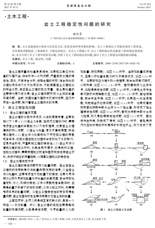
㊃土木工程㊃岩土工程稳定性问题的研究作者简介:谢剑勇(1974-),男,广西灵山人,中级工程师,本科,主要从事岩土工程㊁水文地质工作㊂谢剑勇(广西壮族自治区地球物理勘察院,广西柳州545005)摘㊀要:岩土是地基的主要持力层及受力层,容易受到外界因素的影响㊂岩土工程相比于其他类型的工程来说,具有难度系数较高㊁工程量较大㊁不稳定的特点㊂在岩土工程施工中,岩土工程的稳定性是衡量工程质量的重要指标,本文介绍了岩土工程中的常见问题,分析了岩土工程的稳定性问题,探讨了岩土工程稳定问题的防治措施㊂关键词:岩土工程;稳定性;问题中图分类号:TU195文献标识码:A文章编号:2096-2339(2017)05-0102-02㊀㊀岩土工程质量与地基息息相关,如果施工单位对地基的处理不当,将会引发一系列问题,严重威胁工程的稳定性,因此,只有综合分析㊁选择合理的参数,结合场地的工程地质条件及水文地质条件,才能提高岩土工程施工的安全系数,保证岩土工程的施工质量㊂岩土是地基的主要持力层及受力层,岩土工程问题可视为土体的能量平衡问题㊂当前,我国地基处理技术已相对成熟,但仍然存在一些问题,制约着岩土工程技术的发展㊂1㊀岩土工程常见问题1.1㊀岩土工程的基本范围岩土工程的分类方法很多,从实践层面来看,主要包括以下3种:(1)以岩土为承载,在进行工程设计时,需要考虑岩土地基的承载能力以及变形程度,这是岩土工程建筑的核心问题㊂以岩土为地基,常见于建筑房屋㊁桥梁等工程中;(2)岩土作为地面或地下开挖类工程的荷载或自承体,这类工程在施工过程中会受到地下水的制约,容易发生形变,严重影响工程的稳定性;(3)岩土可作为建筑工程的施工材料,尤其适用于填方㊁修堤筑坝工程㊂在施工过程中,需要根据施工标准和国家规定选用岩土材料,并进行相应的质量控制,以提高工程施工的稳定性㊂1.2㊀岩土工程实施方法岩土工程的稳定问题可视为能量问题㊂岩土在岩土工程中的作用就是它与能量共同作用的结果:①当岩土作为地基时,主要考虑在外加能量下的稳定,如果外界作用力也即外界附加能量大于地基的承载范围,就会导致地基变形,反之,则相对稳定;②作为荷载或者自载体时,主要是能量不平衡下的变形问题;③作为施工材料,则需要考虑本身的能量问题㊂④岩土工程稳定性的根本即是能量问题,岩土加固和改良主要作用是补充岩土体的能量㊂上面四项中,各项之间是相互有机联系的,具有一个共性 补充能量㊂所以,岩土工程的实施主要是解决能量的平衡问题,也就是稳定问题㊂外界能量称之为附加能量(附加荷载),如图1(a)所示㊂当附加能量逐渐增大,但是小于地基承载力时处于稳定状态,如图1(b)所示㊂如果附加应力增大到一定程度,就会出现剪切破坏,以致失稳,如图1(c)㊁(k)所示㊂若视建筑物为土体本身,如路堤稳定性问题,如图1(g)所示;为避免土体发生剪切破坏采用堆载反压,如图1(d)㊁(h)所示,若继续堆载,就会发生失稳,如图1(i)所示;如果在一边继续堆载,则就相当于边坡问题,如图1(e)所示㊂如果视建筑物或者边坡前半部分土体为一个挡土墙,则变成了挡土墙稳定性问题,如图1(m)所示;若视边坡前半部分土体为路堤,则又是路堤稳定性问题,如图1(i)所示㊂若边坡发生失稳,则就成了滑坡,如图1(f)所示㊂若路堤进行反压时所用的材料是废矿料或垃圾土,则又变成了尾图1㊀岩土工程施工方法图201矿库或垃圾填埋问题,如图1(j)所示㊂若边坡直立开挖,就成为深基坑问题,如图1(n)所示㊂2㊀岩土工程的稳定问题2.1㊀工程稳定性分析岩土工程稳定性分析对工程建设的意义重大㊂分析影响岩土工程稳定性的因素能够为工程建设提供理论依据,也会大大提高房屋㊁道路等岩土工程的稳定性和质量㊂当前,岩土工程稳定性分析的现状不容乐观,这是由于岩土工程主要研究的内容为岩土体的承载和变形问题,其影响因素较多,相对复杂㊂岩土工程稳定性分析方法有多种,主要包括:有限单元法㊁极限分析法等,这些方法相对简单,可操作性较强㊂影响岩土工程稳定性的主要因素有:工程因素㊁地质因素㊁地下水等㊂2.2㊀岩土工程的结构设计分析岩土工程的结构设计是决定工程质量的前提,岩土工程的地基是进行施工前必须考察的工作项目,地基的稳定与否直接与工程质量息息相关㊂在对地基进行考察时,为了确保施工安全,要从地质条件㊁承载力以及均匀性等方面进行评价,特别要重视地基承载力的评价㊂地基承载力影响因素很多,主要包括岩土的成因与堆积年代㊁岩土的物理力学性质㊁地下水情况等㊂地基承载力一般分为极限承载力和容许承载力,在设计中必须保证基础底面的压力不超过规定的地基土承载力,以确保岩土不被破坏,同时还要考虑不均匀沉降的问题,确保建筑物不会因沉降差异而使主体承重结构发生开裂㊂因为地基一旦发生形变,不但会影响岩土工程的稳定性,也会对建筑物造成很大的安全隐患㊂因此,需要高度重视岩土工程的结构设计,提高工程质量㊂与此同时,在进行深基坑施工时,应该充分考虑边坡㊁支护等结构设计的稳定性,严格进行支护系统侧压力计算,以强化岩土工程的稳定性,尽可能降低发生形变的几率㊂3㊀岩土工程稳定问题的防治措施3.1㊀岩土工程稳定问题的影响因素岩土工程的性质与能量变化直接相关㊂自然界的能量发生变化,其岩土的特性也随之发生改变㊂由各种原因导致的自然界能量发生变化,会直接影响工程的稳定性㊂在岩土工程中,影响因素主要包括以下几点:第一,自然环境因素(通常表现为地质灾害)㊂洪水㊁地震等自然灾害严重威胁着岩土工程的质量;第二,行为因素㊂岩土工程受到岩土材料的限制,填方㊁采矿等行为会很大程度地破坏地质条件,也会降低岩土工程的稳定性;第三,人为因素㊂岩土工程的实施主体是施工单位,施工时,需要施工人员进行现场核对㊂在最初对场地进行地质勘测时,可能会存在由于人为因素而引起的遗漏㊁情况不属实等问题,或出现施工设计不合理㊁施工程序过于复杂㊁质量控制不严格等问题,进而影响工程的整体质量㊂3.2㊀岩土工程稳定问题的防治要点在岩土工程中,很容易出现岩土形变问题,这主要受到自然界能量不平衡因素的影响㊂岩土工程稳定性不足可以通过改变岩土能量结构解决㊂在施工现场,根据施工的实际情况,科学规划施工结构和施工过程,以降低能量不足发生的几率㊂岩土工程问题防治需要根据不同的影响因素进行科学分析㊁合理规划,以促使岩土工程的能量平衡,提高岩土工程的稳定性和质量㊂对于由常规因素引起的岩土工程稳定性问题,要采取针对性的预防措施,防重于治,避免问题的出现,这是目前最常用㊁最高效的方式㊂3.3㊀抗剪强度指标的选取与优化在对岩土体进行测试过程中,不同条件测定的结果往往差异较大,其数据缺乏代表性的,很难在岩土工程中发挥较大的参考价值,因此,需要采取统一的标准㊂通常,岩土工程测试方法分为三种:室内实验㊁室外测试与检测㊂这三种测试方法得出的结果各有特点,为了保证岩土工程的土体测试质量,需要选定统一的标准㊂水与空气对岩土工程抗剪强度的影响较大,在进行指标选定时,应该充分考虑附加能量作用以及岩土与水的相互作用,以简化测定程序㊂4㊀结语岩土工程的基本问题主要包括岩土工程实施范围和实施方法,研究岩土工程的稳定问题需从工程稳定性结构设计着手㊂影响岩土工程稳定性的因素有:自然因素㊁人为因素以及工程本身的结构因素等,为了提高岩土工程的稳定性,需要根据不同的问题提出相应的防治措施,从而提高工程的整体质量㊂土体抗剪强度指标的选择需要考虑水和空气对土体的影响㊂参考文献:[1]㊀杨㊀峰.岩土工程勘察中关于水文地质问题的相关研究[J].城市地理,2014(16):39-40.[2]曹得占.岩土工程的地基稳定加固处理方案[J].城市建设理论研究(电子版),2014(15).301。

岩土工程学术文献
《产城(上半月)》:岩土工程勘察的质量与工程设计、现场施工及后续审批密切相关。
在当前的岩土工程勘测中传统的的勘测技术和勘测方法已无法满足现代社会的发展要求。
因此,必须加强施工人员的责任,及时更新现有的施工方法和技术,始终根据施工过程进行操作,有效地提高岩土工程勘测的质量,并消除潜在的安全隐患,满足施工质量要求。
因此,施工单位必须重视岩土勘察工作,制定与之相符的政策,并为下一步的工作铺平道路。
《建筑与装饰》:勘察技术是由科学实际地质工程经验所组成的,能够为之后的岩土工程施工提供勘探工作的技术支持,提供多种勘探技术,便于工程施工的勘探工作的顺利进行。
勘探技术在工程施工中的应用,有利于全方面的了解施工地的地质环境条件,对于当地的地质环境因素做出科学分析.先通过对岩土工程施工的勘探现状进行适当分析,然后再分析在岩土工程施工当中所应用的勘探技术,分析问题并提出优化措施,以此来促进之后在工程施工中的应用。

一、SpringerLink(全文)数据库简介(目前可访问的期刊为2236种,期刊前标记为绿色方框表示可访问所有卷的全文,标记为半个绿色方框表示可访问部分卷期的全文;其中大部分期刊是被SCI、EI、SSCI收录的核心期刊)自1996年推出以来,SpringerLink已是全球最大的在线科学、技术和医学(STM)领域学术资源平台。
题范围:自然科学和技术、经济、法律SpringerLink数据库由德国Springer(施普林格)出版社出版,2004年底,Springer与Kluwer Academic Publisher合并。
现在,SpringerLink数据库提供包括原Springer和原Kluwer出版的全文期刊、图书、科技丛书和参考书的在线服务。
具体学科涉及:数学、物理与天文学、化学、生命科学、医学、工程学、计算机科学、环境科学、地球科学、经济学、法律。
SpringerLink的数字资源有:全文电子期刊1500余种;图书和科技丛书(包括Lecture Notes in Computer Science——LNCS)13000种以上;超过200万条期刊文章的回溯记录;最新期刊论文出版印刷前的在线浏览。
电子期刊Springer出版1,900多种经同行评议的学术期刊,大部份拥有自1997年以来已出版的期刊内容。
Springer的在线回溯期刊数据库提供自第一卷第一期起的所有期刊。
Springer拥有大量的高水准ISI期刊,并不断新增学会期刊以及收购其他优质期刊,体现了Springer对提供高品质文献的承诺。
电子图书数据库Springer 的电子图书数据库包括各种的Springer图书产品,如专著、教科书、手册、地图集、参考工具书、丛书等。
SpringerLink在2009年已经出版超过30,000余种在线电子图书,每年将增加3,500种新书,只需轻点鼠标即可获得。
SpringerLink能够成为最受欢迎的在线科学平台之一,其中一个主要原因是Springer每天都会新增高品质的内容:学会刊物、参考工具书、会刊、专著、手册、实验室指南及更多内容。
第xx卷第x期岩土工程学报Vol.xx No.x xxxx年 x月 Chinese Journal of Geotechnical Engineering xxxx, xxxx 基于混沌优化的高阶段充填体可靠性分析刘志祥,李夕兵,张义平(中南大学,湖南长沙 410083)摘要:对高阶段充填体进行了力学分析,推导了分层充填力学计算公式,用可靠性理论研究了高阶段充填体稳定性。
考虑高阶段充填体可靠性分析的状态函数求导困难,提出了基于混沌优化的可靠性计算方法,为工程中复杂函数计算可靠性指标提供了一种新的方法。
高阶段充填体力学研究表明:缩短采场长度和增大采场宽度有利于充填体稳定性和降低充填成本。
为了评价高阶段充填体稳定性,分别在实验室配制充填料浆和采场取样试验了尾砂胶结充填体强度,分析了采场原位充填体强度与实验室试验强度的差异。
研究认为:采用实验室力学参数进行充填设计,最小设计安全系数为1.6~1.8,最小可靠性指标为1.8~2.0比较合理。
用本文方法对安庆铜矿3号高阶段采场充填体进行了可靠性分析,并评价了充填设计的可行性。
关键词:尾砂胶结充填体;分层充填;可靠性;混沌优化中图分类号:TD853.34 文献标识码:A 文章编号:1000–4548(2006)03–0348–05作者简介:刘志祥(1967–),男,湖南宁乡人,中南大学博士后,从事采矿与岩石力学研究。
Reliability analysis of high level backfill based on chaotic optimizationLIU Zhi-xiang, LI Xi-bing, ZHANG Yi-ping(Central South University, Changsha 410083, China)Abstract:Through the mechanical analysis of high backfill, the calculation formulae of the stratified backfill practice were deduced and reliability analysis of their stabilities were studied. In reliability analysis of high backfill, because the differential of status function was difficult to be obtained, a calculating method of reliability based on chaotic optimization was proposed, which was a new method of reliability analysis for complex status function in engineering practice. The mechanical researches showed that reducing length or increasing width of stope were propitious to improve stability of backfill and to lower filling cost. In order to evaluate the stability of backfill, a series of strength experiments of cemented tailings backfill both in the laboratory and under filling stope conditions were done, and their differences of strength were analyzed, as well as a conclusion was drawn that if the mechanical parameters in lab were used as the basis of filling design, the minimum safety factor should be1.6 to 1.8, and the minimum index of reliability should be 1.8 to2.0. Using the present method, the reliable indexes of backfillin stope No. 3 in Anqing copper mine, Anhui province, were calculated, and the feasibility of filling design were evaluated.Key words:consolidated tailings backfill; stratified filling; reliability; chaotic optimization0 引言高阶段采矿是一高效采矿技术[1],大都采用尾砂嗣后充填(矿房胶结充填、矿柱非胶结充填)。
海洋岩土工程文献综述范文# 海洋岩土工程文献综述。
一、引言。
你知道海洋下面的土和岩石可不简单呢!海洋岩土工程就是专门研究海洋环境下岩土相关问题的学科。
这就像是在大海这个超级大的游乐场里,探索那些隐藏在海底的岩土秘密。
在这篇综述里,咱就来好好扒一扒那些关于海洋岩土工程的研究文献,看看科学家们都发现了啥好玩的。
二、海洋岩土工程的独特性。
1. 环境因素。
海洋环境那可是相当复杂。
海水的腐蚀作用就像个小恶魔,不停地侵蚀着岩土结构。
就好比把一块铁放在潮湿的地方会生锈,海里的岩土也会被海水慢慢“折磨”。
文献里提到,盐分、温度变化还有水流速度等都会影响岩土的性质。
比如说,在一些暖流和寒流交汇的海域,岩土受到的腐蚀和冲刷就更严重,就像两个调皮的孩子一起搞破坏。
海洋的波浪荷载也是个大麻烦。
波浪一波又一波地打过来,就像无数个小拳头不停地捶打岩土结构。
这些荷载会让岩土产生变形,严重的话还会导致结构破坏。
有研究就用很复杂的数学模型来模拟波浪荷载对海底地基的影响,看着那些密密麻麻的公式,就像看外星文字一样,但它们确实能算出岩土到底能承受多大的波浪“攻击”。
2. 岩土特性差异。
海洋岩土和陆地上的岩土有很大的区别。
海底的土可能更加松软,就像蛋糕一样,而陆地上有些土可能比较坚硬。
这是因为海洋岩土的形成过程受到海洋生物、沉积环境等多种因素的影响。
有文献指出,海洋里的一些微生物会改变岩土的成分,它们就像小小的建筑工人,在岩土里“添砖加瓦”或者“拆东墙补西墙”,使得岩土的性质变得很奇特。
另外,海底岩土的分层结构也很复杂。
可能一层是软黏土,下面一层又是砂质土,再下面可能还有岩石层。
这种复杂的分层就像一个多层蛋糕,每层的口感(岩土性质)都不一样,给工程建设带来了很大的挑战。
比如说在打桩的时候,如果没有搞清楚下面的岩土分层,桩可能就打不牢,就像把一根筷子插在松松的沙子里,很容易就倒了。
三、海洋岩土工程的研究内容。
1. 海洋地基处理。
为了在海洋上建造各种大型结构,像海上石油平台、跨海大桥的桥墩之类的,必须先把地基处理好。
土木概论的参考文献土木工程是工程学中的一个重要分支,研究的是土地和建筑物的设计、建设和维护。
本文将介绍一些关于土木工程方面的重要参考文献,以帮助读者深入了解这个领域。
1. "Principles of Foundation Engineering" by Braja M. Das这本经典教材是基础工程学中的权威教材之一。
它详细介绍了土壤力学和地基设计的原理和方法。
作者通过丰富的图表和实际案例,向读者提供了解决复杂基础工程问题的工具和知识。
2. "Structural Analysis" by R.C. Hibbeler这本教材是结构工程学的经典之作,涵盖了结构分析的各个方面。
它以清晰简明的语言介绍了不同类型结构的分析方法,包括梁、柱、框架和悬挂结构。
该书还包含了大量的实例和练习题,帮助读者巩固理论知识并应用于实践中。
3. "Construction Methods and Management" by S.W. Nunnally这本教材详细介绍了建筑施工的方法和管理。
作者通过系统性的讲解,向读者展示了不同类型建筑项目的施工流程和管理技术。
该书还包括实例和案例研究,帮助读者了解施工行业的最新趋势和挑战。
4. "Geotechnical Engineering: Principles and Practices" by Donald P. Coduto这本教材是土力学领域的经典之作。
它涵盖了岩土工程的各个方面,包括土体力学、土壤力学和地基设计。
作者通过理论和实践结合的方式,向读者介绍了解决复杂地质工程问题的方法和策略。
5. "Transportation Engineering: An Introduction" by C.JotinKhisty and B.Kent Lall这本教材全面介绍了交通工程学的基本原理和应用。
Chapter 2: Mechanical Behav i our and PropertiesChapter 2.1MODELLING WEATHERING EFFECTS ON THE MECHANICAL BEHAVIOUR OF NATURAL BUILDING STONESRoberto NovaMilan University of Technology (Politecnico), P.za L. da Vinci 32, 20133 Milan, Italy Abstract:The main features of the mechanical behaviour of natural building stones are first recalled. It is shown that a convenient constitutive model can be conceivedin the framework of the theory of strain-hardening plasticity, successfullyapplied to soils and soft rocks. Extension of the theory to chemo-mechanicalconditions is presented and the main results of the numerical analyses of twogeotechnical problems are shown.Key words:soft rocks; plasticity; constitutive modelling; weathering; chemo-mechanics. 1.INTRODUCTIONSoft rocks were extensively used in the past as natural building stones. Limestones, tuffs, calcarenites and similar rocks were in fact employed as construction materials for temples, churches and palaces in all times, all over the world. Their mechanical properties are similar to those of concrete, the principal building stone of our age. They are therefore strong enough to bear high loading but at the same time weak enough to be easily quarried. Lime-stone, for instance, has a tensile strength that is one order of magnitude less than that of granite. They are also widespread so that their cost is limited: an ideal material to work with.The low tensile strength is due to the weakness of the chemical bonds link-ing together the mineral grains constituting the rock skeleton. These bonds are attacked by environmental agents such as water, wind, bacteria, so that their strength is progressively reduced with time of exposure to the atmosphere.The surface degradation of statues and monuments in the polluted air of our metropoleis is an apparent clue of the effect of weathering on natural55S.K. Kourkoulis (ed.), Fracture and Failure of Natural Building Stones, 55–70.© 2006 Springer.56 RobertoNovabuilding stones. The decay of the mechanical properties is not onlysuperficial but extends to the core of the stone, so that even its structuralefficiency can be jeopardised by the action of atmospheric agents.It is therefore of some interest also for engineers to know more about theweathering effects on the mechanical behaviour of natural building stones.Furthermore, it is important to clarify on which lines a constitutive model forsuch materials should be developed in order to cope with the observedphenomena.In this paper, the fundamental properties of soft rocks are recalled first.The way in which phenomena as yielding and subsequent hardening, brittleductile transition, effects of chemical attack can be dealt with is sketchednext. Comparisons with experimental data in laboratory tests and descriptionof the progressive degradation of structures in engineering problems are thenpresented. Finally, a simplified model for structural elements is discussed inelementary cases. It is shown how it is possible to calculate the variation ofthe bearing capacity of a structural element with time.2.GENERALITIES ABOUT THE MECHANICALBEHA VIOUR OF SOFT ROCKSTraditionally, engineers divided natural geomaterials in two classes,depending on the degree of bonding between the mineral grains that consti-tute the geomaterial skeleton: soils and rocks. The former are characterizedby little or no bond strength. Permanent strains take place as soon as loadingis applied and failure is controlled mainly by friction. The latter are char-acterized by large bond strength. Strains are more or less reversible untilfractures occur in the rock mass. Even though, for the sake of simplicity, forhard rocks engineers use a plastic failure criterion, characterized by frictionand cohesion, it is more the fracture energy that controls the strength and thedeformability of such materials.In the last fifteen years, it was recognized that there exists a wide transi-tional class of geomaterials that behave in a way intermediate between theformer two. At low stress levels their stress strain response is qualitativelysimilar to that of a hard rock. On the contrary, at high stress levels theirbehaviour in more similar to that of an unbonded soil. This class of materialswas named hard soils-soft rocks. Many natural building stones, especiallythose characterized by high porosity, belong to it.Typical examples of behaviour are given by Figures 1 and 2 (after Lagioiaand Nova, 1995). Both refer to constant cell pressure triaxial tests on speci-mens of Gravina calcarenite (Southern Italy). In Figure 1 the behaviour ofthree specimens under relatively low confining pressures is shown. The in-itially linear stress - strain behaviour as well as the occurrence of a peak fora certain value of the deviator stress and the following loss of strength andModelling Weathering Effects on the Behaviour of Building Stones 57 strain uniformity of the specimen can be noticed. The peak is in fact associ-ated to the occurrence of a planar fracture across the specimen. From that point onwards, the specimen deformation is essentially due to the sliding of one rigid block over another and strains, calculated as if they were uniform, are meaningless. In Figure 2 the behaviour of a specimen made of the same material but with a much higher confining pressure is shown. Also in this case the initial stress-strain relationship is linear, characterized by a stiffness that is more or less equal to that of the tests at low confining pressure.Yielding occurs in a different way, however. After a while in which the displacement controlled specimen deforms at more or less constant load, hardening takes place up to a failure value characterized by large uniform strains. The clearly observed saw-tooth shape of the constant load step is apparently a clear sign that some sort of instability is occurring. Figure 3 shows that the stiffness in unloading-reloading is not affected by the large permanent strains experienced. In unloading-reloading the behaviour can be therefore assumed to be linear elastic.A convenient conceptual framework to model this behaviour can be constructed, starting from the elasto-plastic strain-hardening model proposed first by the School of Cambridge (Schofield and Wroth, 1968). The fund-amental idea on which such models are based is that it is possible to define a domain in the stress space, as shown in Figure 4, in which the behaviour of the rock can be considered linear elastic.Figure 1.Drained constant cell pressure tests on specimens of Gravina calcarenite con-solidated at low values of confining pressure.58 RobertoNovaFigure 2.Drained constant cell pressure test (ıǯ3 = 900 kPa) on Gravina calcarenite.Figure 3.Constant cell pressure compression test (ıǯ3 = 600 kPa): unloading-reloading cyclesperformed in the elastic phase, the destructuration phase and the hardening phase.Yielding occurs when the stress point touches the frontier of the domain.The occurrence of plastic strains induces either strain-hardening or strain-softening depending on the sign of plastic volumetric strain rates, which inturn is governed by the so-called normality rule. It is apparent from FigureModelling Weathering Effects on the Behaviour of Building Stones 59 4b that such a model can qualitatively describe at least some of the observed features of soft rock behaviour. For instance, it is possible to model the strength increase with the increase of confining pressure, the transition from brittle to ductile behaviour, the occurrence of dilating plastic volumetric strains at small confining pressures, the occurrence of yielding at lower deviator stress levels for higher confining pressures (point H in Figure 4).To obtain quantitative agreement with experimental tests, many things have to be modified. First of all the shape of the yield locus must be as in Figure 5 (Nova, 1992). The normality rule is no more valid and a plastic potential different from the yield function is introduced. Hardening is con-trolled by one parameter linked to the grain structure, p s, as in soil, and two parameters p m and p t related to the existence of bonds, (Nova, 1999; Gens and Nova, 1993). Possibly these latter parameters could be considered proportional to each other. In general, hardening depends on both volumetric and deviatoric plastic strains. With these modifications and appropriate choice of constitutive functions, Lagioia and Nova (1995) were able to reproduce the behaviour of Gravina calcarenite with remarkable accuracy in drained tests with low and high confining pressure, in pǯ constant and undrained tests, in isotropic and oedometric compression. The behaviour of other materials such as tuff, marl, natural and artificial calcarenite, limestone was also simulated (Nova, 1992; Lagioia and Nova; 1993, Nova and Lagioia, 1996).Figure 4.Schematic picture of the Cam Clay model: (a) stress paths in constant cell pressure tests with different overconsolidation ratios; (b) stress-strain behaviour; (c) volumetric strains;(d), (e) normality rule for different stress states.60 Roberto Nova Figure 5.Initial yield surface of cemented (continuous line) and uncemented (dotted line) soil and evolution of the former during destructuration.3.MODELLING OF WEATHERING EFFECTSAs previously discussed, the action of the atmospheric agents alters the intimate structure of geomaterials and influences their mechanical behaviour. It is mainly the plastic part that is affected, while the elastic properties can be considered constant with time, as a first approximation at least. The results presented in Figure 3 show in fact that the mechanical breaking of the bonds associated to plastic strains does not modify the elastic stiffness. Castellanza and Nova (2004) have shown that the elastic properties of an artificial cemented silica sand are not altered by the chemical aggression of an acid. They showed instead that such a chemical attack transforms a soft rock in an assembly of grains without any bonding.To model such a behaviour, the following way of reasoning is possible (Nova, 2000): it is assumed that there exists an elastic domain governed by the following expression:(,,)0ij k f p s p d(1)where p is the isotropic pressure and s ij is the deviator stress: 13ij ij p V G { (2) ij ij ij s p V G { (3) In addition p k is a set of hardening parameters. To make things simple it is assumed here, making reference to Figure 5, that:m t p p D(4)where Į is a constant and *1c c s m s t p p p p p p D { (5)Modelling Weathering Effects on the Behaviour of Building Stones 61The hardening parameter p s depends on the plastic strains experienced p s s ij p p H (6) while p t is assumed to depend on a scalar measure of the degradation, x d , that is linked to the particular process considered. It can be a function of the quartz content in a granite specimen, as in the original definition of Lumb (1962) who studied the weathering of granite. Or it can be a function of the exposure time to an acid attack or to the temperature at which a specimen is tested, and so on. To make things simple it is assumed that:201t t d p p x (7) Several experimental data (Park, 1996; Baynes and Dearman, 1978; Cas-tellanza and Nova, 2004) support this hypothesis for different geomaterials. Clearly, bonds brake also for mechanical reasons, as shown in Figure 2. The value of p t should also depend on plastic strains (Nova et al., 2003):20,1p p t t ij d t t ij d p p x p P x H H (8)For space reasons, it is assumed that P t is a constant equal to 1. Only the non-mechanical agents are considered to be responsible for the degradation of the mechanical properties. Even with this limitation, it is possible to des-cribe interesting phenomena, as it will be seen in the following.Since when plastic strains occur f must be equal to zero before and after the “load” increment (an increment in x d is also considered as a generalized load), the total differential of f must be zero. Therefore0p s t ij rs d p ij s rs t dp p f f f f df dp ds d dx p s p p x H H w w w w w ww w w w w w (9) Since p rs rs g d H V w /w (10)where g(ırs ) is the plastic potential and ȁ is a scalar, called plastic multiplier. Taking account of Eqs.(5) and (7) and solving for ȁ one gets:021ij t d d ij t s p s rs rsf f f dp ds p x dx p s p p f gp H V w w w w w w / w w w w w w (11)62 RobertoNovaFigure 6.Schematic picture of the weathering test device (a) and photograph of the apparatus(b); after Castellanza (2002).From Eq.(11) it is apparent that plastic strains are generated both fromstress increments and by a variation of x d. In particular plastic strains canoccur even under constant stresses.Consider as a special case an oedometric test on an artificial specimen ofsoft rock composed of a mixture of quartz grains and cement constituted byhydraulic lime and water. The test is conducted in the so-called WTD(weathering test device, Figure 6 after Castellanza, 2002). The apparatusconsists of a thin metal ring that laterally constrains the geomaterial speci-men. Un upper and a lower platen are used to load the specimen in thevertical direction. The two platens are permeable so that a fluid (water oracid) can seep through the specimen. Horizontal strains are almost preventedas in a normal oedometer but not completely, since the ring is slightly de-formable. The test is composed of two phases. In the first one the specimenis subject to an increasing vertical loading as in a normal oedometer. In thesecond one, the load is kept constant to the level achieved in the first phaseand an acid is forced to seep into the specimen. With time, the acid dissolvesthe calcareous bonds so that further vertical strains take place.A very sensible strain gauge is attached along the circumference of theright section of the ring. This can record the circumferential strains and fromthose it is possible to determine the radial stresses by means of the Mariotteformula. Therefore the entire stress path can be determined.Figures 7-10 (after Nova et al., 2003) show the comparisons of the expe-rimental and calculated stress path, radial stresses, vertical settlements andthe variation of the calculated internal variables for a specimen of cementedsilica sand. The constitutive model used is presented in detail in Nova et al.(2003), where also more complex tests are considered.It is apparent that the model proposed can describe with sufficient ac-curacy the effects of weathering on specimens of soft rock.Modelling Weathering Effects on the Behaviour of Building Stones 63Figure 7.Experimental versus calculated stress paths in a weathering test on cemented silicasand, after Nova et al. (2003).Figure 10.Evolution of the calculated internal variables for the stress path of Figure 7 (after Nova et al. (2003). xxFigure 8.Experimental versus calculatedradial stress for the stress path shown inFigure 7, after Nova et al. (2003).Figure 9.Experimental versus calculated vertical strains for the stress path shown inFigure 7, after Nova et al. (2003).4.APPLICATIONSBy employing the model of Nova et al. (2003), Castellanza et al. (2002) showed that it is possible to simulate the progressive failure of geostructures, subjected to chemically induced bond degradation. In Lorraine, for instance, several collapses were caused by the progressive degradation of the pillars of abandoned iron mines, attacked by bacteria, which live in the water that flooded the mine chambers after the end of the mining activities.The damage progression was simulated simply by imposing a degradation law to the pil-lars. The closer the rock element is to the flooded chamber, the higher is the value of x d (up to one that corresponds to full degradation). The value of x d increases with time at a conveniently established rate. Furthermore the zone of the pillar affected by degradation also increases with time at a given rate.The results obtained are shown in Figure 11. The main effect of the de-gradation is that of reducing the bearing capacity of the layers that are more exposed to the chemical attack. There is therefore a progressive stress migra-tion towards the centre of the pillar that can eventually collapse under the weight of the overburden that cannot be sustained anymore. Figure 11b shows how relevant can be the weathering induced displacements at the surface with respect to the original ones due solely to mine excavation.(a)(b)Figure 11.Subsidence induced by the degradation of the pillars of an abandoned iron mine;(a) Stress redistribution within the pillar; (b) Settlements, after Castellanza et al. (2002).Recently, Parma (2004) considered the effect of a pollutant migrating with-in a bonded soil mass on the settlement of a shallow foundation. To solve this problem, the contaminant diffusion equations were treated by means of a finite difference computer code combined with GeHoMadrid, the finite ele-ment code (Fernandez Merodo et al., 1999) in which the aforementioned Nova et al. model is implemented.Figure 12 shows the evolution of the contaminant, the associated plastic strains induced by chemical degradation and the progression of the found-ation settlements with time. It is apparent that the calculated results look reasonable. A series of experimental tests are presently performed in Milan on a model foundation resting on an artificially cemented soil, to have a benchmark against which checking the validity of the proposed theory.(a) (b) (c) Figure 12.Effects of the diffusion of a contaminant under a shallow foundation; (a) Variation of x d; (b) Deviatoric plastic strains; (c) Vertical displacements for successive time steps (Parma, 2004).5.SIMPLIFIED MODEL FOR STRUCTURALBEHA VIOUR OF NATURAL BUILDING STONES The conceptual structure of the constitutive model presented so far can be applied to structural problems involving the weathering of natural building stones. To achieve this goal, a simplified model is formulated in this section. At variance with foundation soils, structural elements are not laterally confined. Therefore the range of interest is that of low confining pressures, where the natural building stones behaviour is qualitatively similar to that of hard rocks. The yield condition is therefore also a failure condition, since yielding is associated to negative hardening values (softening) and a sharp peak occurs in the deviatoric stress-strain law. It is apparent from Figure 13 that such a failure condition can be approximated by a straight line of equationm q mp q c (12) at least for positive p ǯ. It is also shown in Figure 13 that as the degradation proceeds, m remains more or less constant, while q m decreases more or less in proportion to p m . One can therefore assume that the unconfined compressive strength of a natural building stone q C varies with the weathering degree as201C C d q q x (13) or even more simply as01C C d q q x (14) The plastic potential rules the ratio of plastic strains. A constant dilation rate can be assumed again for the sake of simplicityp p v d H \H (15) where p v Hand p d H are the volumetric and deviatoric plastic strain rates, res-pectively. Furthermore, the value of q C can be made to depend on plasticstrain experienced, for instance as:C C C p d q q U H w w (16)If ȡc is taken to be zero, a ductile behaviour is assumed after yielding. If ȡc is taken to be infinite, a perfectly brittle behaviour is considered. This latter possibility is considered here. In practice, this means that when a ma-terial element reaches the yielding condition it suddenly looses the ability of bearing stress. The existing stress must be therefore instantaneously trans-ferred to the parts that have not yet yielded to guarantee the fulfilment of equilibrium. Finally, in accordance with many experimental observations, the elastic moduli are considered to be constant, affected neither by weather-ing nor by the occurrence of plastic strains.6.AN ANALYSIS OF THE STABILITY OF A CIRCUL-AR PILLAR SUBJECTED TO WEATHERINGAs an application, consider a cylindrical pillar with circular cross section subjected to a constant load Q (consider negligible the pillar own weight). When the pillar is intact at time zero the pillar contraction is given by020QL E R G G S { (17)where L is the height of the pillar, R 0 its radius and E the Young’s modulus of the material. Assume now that weathering affects the lateral surface of the pillar and progresses towards the centre of the pillar linearly with time. The front of intact rock is therefore at a distance from centre equal to0R R t D (18) Assuming that the behaviour is perfectly brittle, the rock strength in a point at distance R falls to zero as soon as the front reaches it. The pillar therefore collapses abruptly when:200c Q R t S D V (19) where ıc0 is the compressive strength of the stone. This occurs for a time t fafter weathering begins equal to:01f R t D ° ®°¯ (20)The contraction increases with time as:022200011QLt t E R R R G G D D S §·§· ¨¸¨¸©¹©¹ (21)until the time of failure is achieved and then sudden collapse occurs. The displacement corresponding to t f according to Eq.(20) is equal to:00f Q Q G G (22) where Q 0 is the force the intact pillar can bear. The results are summarized in Figure 14. The values of the parameters of Eqs.(20) and (21) can be de-termined either by recording the contraction variation with time or by per-forming appropriate tests in the laboratory. To give an order of magnitude, by assuming that the degradation front progresses at 1 mm/year for a column with a diameter 1 m wide loaded at 0.1 of its bearing capacity in non-weathered conditions, the failure time is 342 years. This time reduces to 146 years if the load is one half of the bearing capacity.7.CONCLUSIONSOften old constructions are made of natural materials belonging to the class of soft rocks. Their behaviour is intermediate between that of a hard rock and that of a soil and depends on the confining pressure and the degreeFigure 14.of weathering. At high confining pressures or high weathering degree the rock behaves as a soil, which is as an unbonded material (no cohesion).By exploiting the conceptual framework of soil models, with appropriate modifications to take the role of bonding into account, it is possible to model the behaviour of rock specimens under mechanical loading and/or chemical attack, with reasonable agreement between experimental data and numerical results. The constitutive model developed can be implemented in a finite element code and, in principle, any type of boundary value problem can be tackled, taking into account the effect of progressive chemical weathering. Two geotechnical problems were discussed.Also structural problems could be analysed in the same way. However, since in this case the load condition is simple, simplified methods may be used. Such methods can be derived by drawing inspiration from the more realistic 3D model described here. A simple model for evaluating the life-time of a column under centrally loaded subject to environmental degra-dation was finally proposed.REFERENCESBaynes F. J., and Dearman, W. R., 1978, The relationship between the microfabric and the engineering properties of weathered granite, Bulletin of the International Association of Eng. Geol.18:191-197.Castellanza R., 2002, Weathering effects on the mechanical behaviour of bonded geoma-terials: an experimental, theoretical and numerical study, PhD Thesis, Politecnico di Milano.Castellanza R., Nova R., 2004, Oedometric Tests on Artificially Weathered Carbonatic Soft Rocks,J. Geotechnical and Geoenvironmental Engineering ASCE 130(7):728-739. Castellanza R., Nova R., Tamagnini C., 2002, Mechanical effects of chemical degradation of bonded geomaterials in boundary value problems, Rev. Fran. Génie Civil6(6):1169-1192.Gens A., Nova R., 1993, Conceptual bases for a constitutive model for bonded soils and weak rocks, in Proceedings of the International Symposium on Hard soils-soft rocks, Athens, 485-494.Lagioia R., Nova R., 1993, A constitutive model for soft rocks, in Proceedings of the International Symposium on Hard soils-soft rocks, Athens, pp. 625-632.Lagioia R, Nova R., 1995, An experimental and theoretical study of the behaviour of a cal-carenite in triaxial compression. Géotechnique45(4):633–648.Lumb P., 1962, The properties of decomposed granite, Géotechnique12:226-243.Nova R., 1992, Mathematical modelling of natural and engineered geomaterials. General lecture 1st E.C.S.M. Munchen, European J. Mech. A/Solids11(Special issue):135–154. Nova R., 2000, Modelling weathering effects on the mechanical behaviour of granite, in Con-stitutive Modelling of Granular Materials, D. Kolymbas editor, Springer, Berlin, 397-411. Nova R., Castellanza R, Tamagnini C., 2003, A constitutive model for bonded geomaterials subject to mechanical and/or chemical degradation. Int. J. Num. Anal. Meth. Geomech.27(9):705–732.Nova R., Lagioia R., 1996, Soft Rocks: Behaviour and Modelling” Keynote lecture, Proc.Eurock ’96, Turin, Balkema 2000, 3, 1521-1540.Parma M., 2004, Modellazione dell’accoppiamento chemo-meccanico nei materiali cementati, Tesi di Laurea (in Italian).Park H. D., 1996, Assessment of the geotechnical properties of the weathered rocks at historical monuments in Korea, in Proceedings of Eurock ’96, edited by G. Barla, Balkema, Rotterdam, 1413-1416.Schofield A. N., Wroth C. P., 1968, Critical State Soil Mechanics, McGraw Hill, New York.。