利雅路(Riello) 燃烧器 使用说明书RS5
- 格式:pdf
- 大小:398.40 KB
- 文档页数:12
强制通风燃气燃烧器平滑二段火或比例调节运行代码型号类型3753883GAS 8 P/M538 T80 3753884GAS 8 P/M538 T80 3754083GAS 9 P/M540 T80 3754084GAS 9 P/M540 T80 3754185GAS 10 P/M541 T80 3754186GAS 10 P/M541 T80 3754187GAS 10 P/M541 T80 3754188GAS 10 P/M541 T80目录 页码1概述. . . . . . . . . . . . . . . . . . . . . . . . . . . . . . . . . . . . . . . . . . . . . . .31.1技术参数 . . . . . . . . . . . . . . . . . . . . . . . . . . . . . . . . . . . . . . . . . . .31.2可选型号 . . . . . . . . . . . . . . . . . . . . . . . . . . . . . . . . . . . . . . . . . . .31.3燃烧器描述 . . . . . . . . . . . . . . . . . . . . . . . . . . . . . . . . . . . . . . . . .41.4包装 重量. . . . . . . . . . . . . . . . . . . . . . . . . . . . . . . . . . . . . . . . . . .41.5最大尺寸 . . . . . . . . . . . . . . . . . . . . . . . . . . . . . . . . . . . . . . . . . . .41.6标准配件 . . . . . . . . . . . . . . . . . . . . . . . . . . . . . . . . . . . . . . . . . . .41.7附件. . . . . . . . . . . . . . . . . . . . . . . . . . . . . . . . . . . . . . . . . . . . . . .51.8出力图. . . . . . . . . . . . . . . . . . . . . . . . . . . . . . . . . . . . . . . . . . . . .61.9测试锅炉 . . . . . . . . . . . . . . . . . . . . . . . . . . . . . . . . . . . . . . . . . . .61.10燃气压力 . . . . . . . . . . . . . . . . . . . . . . . . . . . . . . . . . . . . . . . . . . .62安装. . . . . . . . . . . . . . . . . . . . . . . . . . . . . . . . . . . . . . . . . . . . . . .72.1锅炉板. . . . . . . . . . . . . . . . . . . . . . . . . . . . . . . . . . . . . . . . . . . . .72.2燃烧头长度 . . . . . . . . . . . . . . . . . . . . . . . . . . . . . . . . . . . . . . . . .72.3将燃烧器固定在锅炉上 . . . . . . . . . . . . . . . . . . . . . . . . . . . . . . . .82.4设置燃烧头 . . . . . . . . . . . . . . . . . . . . . . . . . . . . . . . . . . . . . . . . .82.5燃气管路 . . . . . . . . . . . . . . . . . . . . . . . . . . . . . . . . . . . . . . . . . . .92.6电气设备,工厂设置 . . . . . . . . . . . . . . . . . . . . . . . . . . . . . . . . .102.7电气设备,安装人员设置. . . . . . . . . . . . . . . . . . . . . . . . . . . . . .103点火前的控制与校准 . . . . . . . . . . . . . . . . . . . . . . . . . . . . . . . . .133.1锅炉. . . . . . . . . . . . . . . . . . . . . . . . . . . . . . . . . . . . . . . . . . . . . .133.2燃气管道 . . . . . . . . . . . . . . . . . . . . . . . . . . . . . . . . . . . . . . . . . .133.3助燃空气 . . . . . . . . . . . . . . . . . . . . . . . . . . . . . . . . . . . . . . . . . .143.4电气系统 . . . . . . . . . . . . . . . . . . . . . . . . . . . . . . . . . . . . . . . . . .143.5燃烧器启动 . . . . . . . . . . . . . . . . . . . . . . . . . . . . . . . . . . . . . . . .144燃烧器点火 . . . . . . . . . . . . . . . . . . . . . . . . . . . . . . . . . . . . . . . .155燃烧器校准 . . . . . . . . . . . . . . . . . . . . . . . . . . . . . . . . . . . . . . . .155.1设置燃烧头 . . . . . . . . . . . . . . . . . . . . . . . . . . . . . . . . . . . . . . . .155.2设置伺服马达. . . . . . . . . . . . . . . . . . . . . . . . . . . . . . . . . . . . . . .165.3设置燃气压力. . . . . . . . . . . . . . . . . . . . . . . . . . . . . . . . . . . . . . .175.4设置燃烧器出力. . . . . . . . . . . . . . . . . . . . . . . . . . . . . . . . . . . . .175.4.1设置最大出力. . . . . . . . . . . . . . . . . . . . . . . . . . . . . . . . . . . . . . .185.4.2设置最小出力. . . . . . . . . . . . . . . . . . . . . . . . . . . . . . . . . . . . . . .195.4.3设置中间出力. . . . . . . . . . . . . . . . . . . . . . . . . . . . . . . . . . . . . . .205.5设置空气压力开关. . . . . . . . . . . . . . . . . . . . . . . . . . . . . . . . . . .205.6设置最大燃气压力开关 . . . . . . . . . . . . . . . . . . . . . . . . . . . . . . .205.7设置最低燃气压力开关 . . . . . . . . . . . . . . . . . . . . . . . . . . . . . . .205.8设置燃烧 . . . . . . . . . . . . . . . . . . . . . . . . . . . . . . . . . . . . . . . . . .215.9火焰监测 . . . . . . . . . . . . . . . . . . . . . . . . . . . . . . . . . . . . . . . . . .216运行. . . . . . . . . . . . . . . . . . . . . . . . . . . . . . . . . . . . . . . . . . . . . .227最终控制装置. . . . . . . . . . . . . . . . . . . . . . . . . . . . . . . . . . . . . . .238燃气流量测量. . . . . . . . . . . . . . . . . . . . . . . . . . . . . . . . . . . . . . .239燃烧器不运行. . . . . . . . . . . . . . . . . . . . . . . . . . . . . . . . . . . . . . .2310维护. . . . . . . . . . . . . . . . . . . . . . . . . . . . . . . . . . . . . . . . . . . . . .2511附表. . . . . . . . . . . . . . . . . . . . . . . . . . . . . . . . . . . . . . . . . . . . . .26注意事项注意事项::在文本中所提及的图形标识按如下说明:1)(A)= 图(A)的第1部分,与文本的同页;1)(A)p.4= 图(A)的第1部分,页码为4;1)= 所提及最后一张图的第1部分。

CODEMODEL TYPE3751917 - 3751918GAS 3519 T13751617GAS 4516 T13751717GAS 5517 T13751817GAS 6518 T1GAS安装、使用以及维护说明书燃气燃烧器GAS 3-4-5-6目录技术参数-------------------------------------------------------2 附件----------------------------------------------------------------3 燃烧器描述----------------------------------------------------------4 包装重量------------------------------------------------------------4 最大尺寸------------------------------------------------------------4 标准配件------------------------------------------------------------4 燃烧出力------------------------------------------------------------5 商业锅炉------------------------------------------------------------5 测试锅炉------------------------------------------------------------6 燃气压力------------------------------------------------------------6 安装-----------------------------------------------------------7锅炉板--------------------------------------------------------------7 燃烧头的长度--------------------------------------------------------7 燃烧器固定在锅炉上--------------------------------------------------7 燃烧头的设置--------------------------------------------------------8 燃气管线------------------------------------------------------------9 电气系统-----------------------------------------------------------10 首次点火前的调整---------------------------------------------------13 燃烧器启动---------------------------------------------------------13 燃烧器点火---------------------------------------------------------13 燃烧器校准---------------------------------------------------------14 1.点火输出功率--------------------------------------------------14 2.最大输出功率--------------------------------------------------15 3.空气压力开关--------------------------------------------------15 4.最低燃气压力开关----------------------------------------------15 火焰状况检查-------------------------------------------------------15 燃烧器运行---------------------------------------------------------16 最终检查-----------------------------------------------------------17 维护保养-----------------------------------------------------------17 故障表-----------------------------------------------------18 燃烧器启动循环诊断-----------------------------------------20运行故障诊断--------------------------------------------------------20技术参数型号GAS3 GAS4 GAS5 GAS6 类型 519T1 516T1 517T1 518T1 出力 KW 130-350 185-465 325-660 525-1050Mcal/h 112-301 160-400 280-570 450-900 燃料 天然气:G20-G21-G22-G23-G25G20 G25 G20 G25 G20 G25 G20 G25热值 kwh/Nm 310 8.6 10 8.6 10 8.6 10 8.6Mcal/Nm 38.6 7.4 8.6 7.4 8.6 7.4 8.6 7.4比重 kg/Nm 30.71 0.78 0.71 0.78 0.71 0.78 0.71 0.78 最大出力 Nm 3 /h 35 43 47 54 66 77 105 122 最大压力 mbar 11.1 16.4 9.8 14.5 9.8 14.5 12.3 18.2 运行 — 间断工作(每24小时停一次)—1段火工作标准应用 锅炉:热水、蒸汽、导热油炉环境温度 ℃ 0-40 助燃空气 ℃max 60 V 230~+/-10% 230-400(带零线)~+/-10% 电源 Hz 50-单相 50-三相rpm 2750 2810 2870 2840 kW 0.250 0.370 0.750 1.5 V 220 220 220/380 220/380 240 240 240/415 240/415 电机A 1.8 2.9 2.85-1.65 5.9-3.4μF 8 12.5 电容 V 450/500 400/450点火变压器 V1-V2 I1-I2230V-1×8kV1.8A-30mA电耗 kW max 0.4 0.54 0.85 1.7电保护 IP40 电磁干扰符合90/396-89/336-73/23-92/42审核标准CE 0085AQ0707(1) 参考条件:环境温度20℃,大气压力为100mbar(2) 测试点12)(A)p.4处的压力,燃烧室压力为零,燃气环2)(B)p.8开启,燃烧器输出功率最大(A)(B)(A)(B)mm A B C kg GAS 385047354532GAS 485047354538GAS 589552054341GAS 6104555554358mm A B C D E F G H I L M GAS 3205205292140Rp11/216597185775610397GAS 4205205292150Rp11/216597187775610397GAS 5226205332155Rp11/216597207810645437GAS 6258205370175Rp2195131227966770485(C)D989D990D88D231燃烧器部件说明(A )1. 燃烧器滑杆,为打开检修燃烧器用。
2915915 (0)CODEMODELTYPE3751917 - 3751918GAS 3519 T13751617GAS 4516 T13751717GAS 5517 T13751817GAS 6518 T1GAS安装、使用以及维护说明书燃气燃烧器GAS 3-4-5-6目录技术参数-------------------------------------------------------2附件----------------------------------------------------------------3燃烧器描述----------------------------------------------------------4包装重量------------------------------------------------------------4最大尺寸------------------------------------------------------------4标准配件------------------------------------------------------------4燃烧出力------------------------------------------------------------5商业锅炉------------------------------------------------------------5测试锅炉------------------------------------------------------------6燃气压力------------------------------------------------------------6安装-----------------------------------------------------------7锅炉板--------------------------------------------------------------7燃烧头的长度--------------------------------------------------------7燃烧器固定在锅炉上--------------------------------------------------7燃烧头的设置--------------------------------------------------------8燃气管线------------------------------------------------------------9电气系统-----------------------------------------------------------10首次点火前的调整---------------------------------------------------13燃烧器启动---------------------------------------------------------13燃烧器点火---------------------------------------------------------13燃烧器校准---------------------------------------------------------141.点火输出功率--------------------------------------------------142.最大输出功率--------------------------------------------------153.空气压力开关--------------------------------------------------154.最低燃气压力开关----------------------------------------------15火焰状况检查-------------------------------------------------------15燃烧器运行---------------------------------------------------------16最终检查-----------------------------------------------------------17维护保养-----------------------------------------------------------17故障表-----------------------------------------------------18 燃烧器启动循环诊断-----------------------------------------20运行故障诊断--------------------------------------------------------201技术参数型号GAS3 GAS4 GAS5 GAS6类型519T1 516T1 517T1 518T1出力KW 130-350 185-465 325-660 525-1050 Mcal/h 112-301 160-400 280-570 450-900燃料天然气:G20-G21-G22-G23-G25G20 G25 G20 G25 G20 G25 G20 G25热值kwh/Nm3 10 8.6 10 8.6 10 8.6 10 8.6Mcal/Nm38.6 7.4 8.6 7.4 8.6 7.4 8.6 7.4比重kg/Nm30.71 0.78 0.71 0.78 0.71 0.78 0.71 0.78最大出力Nm3/h 35 43 47 54 66 77 105 122 最大压力mbar 11.1 16.4 9.8 14.5 9.8 14.5 12.3 18.2运行—间断工作(每24小时停一次)—1段火工作标准应用锅炉:热水、蒸汽、导热油炉环境温度℃ 0-40助燃空气℃max 60V 230~+/-10% 230-400(带零线)~+/-10% 电源Hz 50-单相 50-三相rpm 2750 2810 2870 2840kW 0.250 0.370 0.750 1.5V 220 220 220/380 220/380240 240 240/415 240/415 电机A 1.8 2.9 2.85-1.65 5.9-3.4μF 8 12.5电容V 450/500 400/450点火变压器V1-V2I1-I2 230V-1×8kV 1.8A-30mA电耗kW max 0.4 0.54 0.85 1.7电保护 IP40电磁干扰符合90/396-89/336-73/23-92/42审核标准CE 0085AQ0707(1)参考条件:环境温度20℃,大气压力为100mbar(2)测试点12)(A)p.4处的压力,燃烧室压力为零,燃气环2)(B)p.8开启,燃烧器输出功率最大重要提示:由安装者负责其它不在此说明书中提到的安全设备。
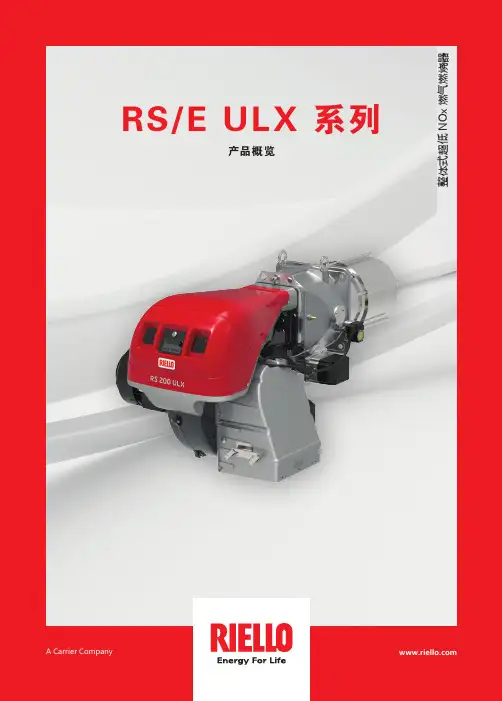
整体式超低 N O x 燃气燃烧器RS/E ULX 系列产品概览A Carrier Company RS/E ULX 系列 | 整体式超低 NOx 燃烧器氮氧化物排放能够低于40mg/Nm 3 @ 3,5% O 2(无 FGR, 需要合适的炉膛尺寸)对于一些应用,NO x 排放可以达到 30mg/Nm 3 @ 3.5% O 2 以下,但需要利雅路工程师确认。
超低 NOX整体式燃气燃烧器RS 68 - 510/E ULX 系列2RS 68/E ULXRS 120/E ULXRS 200/E ULXRS 310/E ULXRS 510/E ULX3RS/E ULX 系列 | 整体式超低 NOx 燃烧器为了满足日益增长的对极低 NOx 排放的要求,利雅路基于创新的 ULX 燃烧技术,开发了整体式的新系列燃烧器。
ULX 燃烧技术可以控制燃烧过程中产生的烟气量,从而达到最严格的排放限制。
在无需FGR装置以及从烟囱到燃烧器管道的情况下,ULX 燃烧技术可以使得氮氧化物排放低于40mg/Nm3 @3.5% O2 (无FGR,需要合适的炉膛尺寸)。
对于一些应用,NOx排放可以达到30mg/Nm3 @ 3.5% O2 以下,但需要利雅路工程师确认。
近年来,由于污染大幅度增加,全球各地特别是所有高度工业化国家,都对产品的性能、能效和排放物的减排更加关注。
ULX 燃烧技术—环境可持续发展的新里程碑新型 ULX 燃烧头采用燃气分级燃烧和废气内部再循环技术,极大地降低了 NOx 排放。
这种新型燃烧头体现了利雅路产品一贯的坚固性和可靠性。
集成的燃烧器数字控制系统,通过独立的伺服马达,可以控制每个出力点的空气和燃料比例,以达到非常低的 NOx 排放,同时使燃烧器保持极高的运行可靠性和安全性。
4>使用 ULX 燃烧技术后,无需再安装 FGR 系统通常所需要的管道系统,因此燃烧器的安装也更加方便。
>无需在锅炉房中安装管道,可以节省空间、时间和安装成本。
燃气燃烧器目录技术参数--------------------------------------------------------------------------------------------------------------------1 变型燃烧头-----------------------------------------------------------------------------------------------------------------1 L G P组件--------------------------------------------------------------------------------------------------------------------1 燃烧器描述-----------------------------------------------------------------------------------------------------------------2 包装-重量-----------------------------------------------------------------------------------------------------------------2 最大尺寸---------------------------------------------------------------------------------------------------------------------2标准附件---------------------------------------------------------------------------------------------------------------------2燃烧出力---------------------------------------------------------------------------------------------------------------------3测试锅炉---------------------------------------------------------------------------------------------------------------------3商用锅炉---------------------------------------------------------------------------------------------------------------------3燃气压力---------------------------------------------------------------------------------------------------------------------4安装--------------------------------------------------------------------------------------------------------------------------- 5 锅炉板------------------------------------------------------------------------------------------------------------------------ 5 燃烧头长度------------------------------------------------------------------------------------------------------------------5 燃烧器固定到锅炉上------------------------------------------------------------------------------------------------------5 设定燃烧头------------------------------------------------------------------------------------------------------------------6 阀门组------------------------------------------------------------------------------------------------------------------------7 电气系统--------------------------------------------------------------------------------------------------------------------8 点火前调整-----------------------------------------------------------------------------------------------------------------11 伺服电机------------------------------------------------------------------------------------------------11燃烧器起动-----------------------------------------------------------------------------------------------------------------11 燃烧器点火-----------------------------------------------------------------------------------------------------------------11 燃烧器校准-----------------------------------------------------------------------------------------------------------------12 1-点火输出功率----------------------------------------------------------------------------------------------------------12 2-最大输出功率-------------------------------------------------------------------------------------------------------12 3-最小输出功率------------------------------------------------------------------------------------------------------13 4-中间输出功率---------------------------------------------------------------------------------------------------------13 5-空气压力开关---------------------------------------------------------------------------------------------------------14 6-最大燃气压力开关--------------------------------------------------------------------------------------------------147-最低燃气压力开关--------------------------------------------------------------------------------------------------14 火焰有无检查------------------------------------------------------------------------------------------------------------14 燃烧器运行----------------------------------------------------------------------------------------------------------------15 最终检查------------------------------------------------------------------------------------------------------------------16 维护-------------------------------------------------------------------------------------------------------------------------1 6 状态/L E D面板-----------------------------------------------------------------------------------------------------------17 故障-可能的原因-排障建议-----------------------------------------------------------------------------------------18 本文中所提到的图形如下标识:1)(A)=图A的第1部分,与文本同页1)(A)p.4=图A的第1部分,页号4技术参数1) 参考条件:环境温度20℃,表压1000mbar,海拔100m2) 测试点16)(A)p.2处的压力,燃烧室压力为零,燃气环2)(B)p.7开启,燃烧器输出功率最大。
安装,使用和维修说明书强制通风燃气燃烧器RS28-38-502915932 (0)平滑两段火运行目录技术参数 . . . . . . . . . . . . . . . . . . . . . . .页2变量 (2)附件 (2)燃烧器描述 (3)包装-重量 (3)最大尺寸 (3)标准配置 (3)出力范围 (4)测试锅炉 (4)商业用锅炉 (4)燃气压力 (5)安装 . . . . . . . . . . . . . . . . . . . . . . . . . . . . . . . . . . . . . . . . . . . . . . . 6锅炉安装板 (6)燃烧筒长度 (6)燃烧器正确安装到锅炉 (6)燃烧头的设置 . . . . . . . . . . . . . . . . . . . . . . . . . . . . . . . . . . . . . . . . 7燃气管路. . . . . . . . . . . . . . . . . . . . . . . . . . . . . . . . . . . . . . . . . . . . 8电气系统. . . . . . . . . . . . . . . . . . . . . . . . . . . . . . . . . . . . . . . . . . . . 9首次点火前的设置项目. . . . . . . . . . . . . . . . . . . . . . . . . . . . . . . . 12伺服马达. . . . . . . . . . . . . . . . . . . . . . . . . . . . . . . . . . . . . . . . . . . 12燃烧器首次启动 . . . . . . . . . . . . . . . . . . . . . . . . . . . . . . . . . . . . . 12燃烧器点火. . . . . . . . . . . . . . . . . . . . . . . . . . . . . . . . . . . . . . . . . 12燃烧器校核: . . . . . . . . . . . . . . . . . . . . . . . . . . . . . . . . . . . . . . . . 13 1-燃烧器出力. . . . . . . . . . . . . . . . . . . . . . . . . . . . . . . . . . . . . . . 13 2-二段火出力. . . . . . . . . . . . . . . . . . . . . . . . . . . . . . . . . . . . . . . 13 3-一段火出力. . . . . . . . . . . . . . . . . . . . . . . . . . . . . . . . . . . . . . . 14 4-中间负荷出力. . . . . . . . . . . . . . . . . . . . . . . . . . . . . . . . . . . . . 14 5-空气压力开关. . . . . . . . . . . . . . . . . . . . . . . . . . . . . . . . . . . . . 15 6-最低燃气压力开关 . . . . . . . . . . . . . . . . . . . . . . . . . . . . . . . . . 15火焰检查. . . . . . . . . . . . . . . . . . . . . . . . . . . . . . . . . . . . . . . . . . . 15燃烧器运行. . . . . . . . . . . . . . . . . . . . . . . . . . . . . . . . . . . . . . . . . 16最终检查. . . . . . . . . . . . . . . . . . . . . . . . . . . . . . . . . . . . . . . . . . . 17维修 . . . . . . . . . . . . . . . . . . . . . . . . . . . . . . . . . . . . . . . . . . . . . . 17燃烧器启动循环诊断 . . . . . . . . . . . . . . . . . . . . . . . . . . . . . . . . . 18重置控制盒和使用故障诊断表 . . . . . . . . . . . . . . . . . . . . . . . . . . 18故障-可能原因-建议解决方案. . . . . . . . . . . . . . . . . . . . . . . . . 19显示器(选配) . . . . . . . . . . . . . . . . . . . . . . . . . . . . . . . . . . . . . 20提示:.在正文中出现的符号代表如下的意义:1)(A)=同一页中图 A的第1 部件;1)(A)p.3=第3页中图 A的第1 部件注意根据效率规范92/42/EEC有关锅炉配置燃烧器的规定,燃烧器的调整和测试须参照锅炉的使用说明书,诸如烟气中的 CO和 CO2 的浓度,烟气的温度和锅炉内的平均水温。
利雅路燃烧器安装说明标准化管理处编码[BBX968T-XBB8968-NNJ668-MM9N]
一、喷嘴的安装:
1、核对喷嘴型号,每个数值的油耗为4.2KG/H。
2、取下末端锥筒
3、取下风量调节筒
4、取下稳焰盘组件
5、取下塑料塞子后,用16mm扳手将喷嘴进行安装。
请勿使用任何密封材料,注意不要损坏喷嘴的密封垫。
安装时喷嘴必须拧到位,但不要拧脱扣。
6、点火装置调节(一般情况不需要调节)
二、燃烧头调节(一般不需要调节)
根据出力大小,按说明书提供图表调整刻度盘至相应位置
三、油路安装
1、按照箭头方向安装进油管和回油管,过滤器安装在进油管路上。
四、电气连接
1、交流220V供电,接X7插头。
2、公司一般通过控制电源通断控制燃烧器工作,需将X7插头T1、T2端子短接。
3、如需二段火运行,需将X4插头T6、T8端子短接。
注:小型燃烧机(G20)接线端子⊙为故障输出的指示灯接线端子,千万不要接地。
五、启动
1、检查油路、电气连接是否正确。
2、松开油泵下的螺栓V,排除泵中的空气。
3、启动燃烧器,油泵方向必须与所标示一致。
如果螺栓V处有油漏出,油泵注油成功。
关闭燃烧器,拧紧螺栓。
六、烟度调节
黑烟为燃烧不充分,需调大风门。
白烟为风量过大,需调小风门。
二段火工作时的风门调节一般调整一段火风门是燃烧机顺利点火为宜,调整二段火风门至要求烟度。
调整完成后,拧紧防活动螺丝。
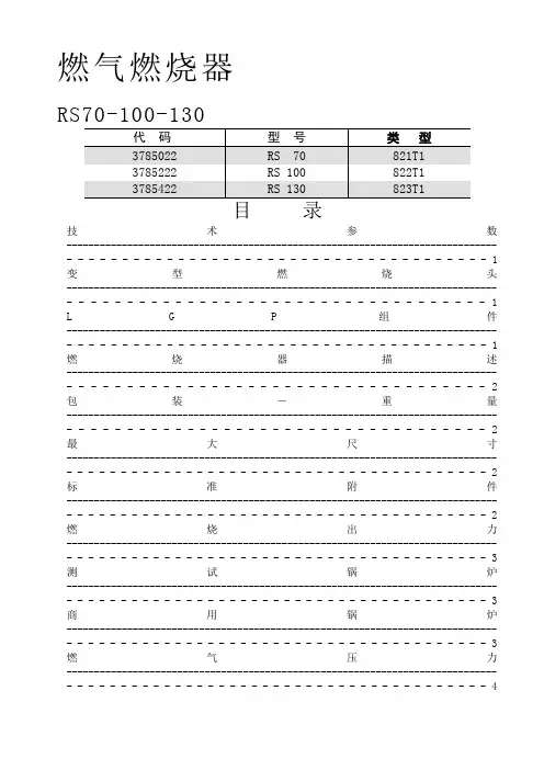
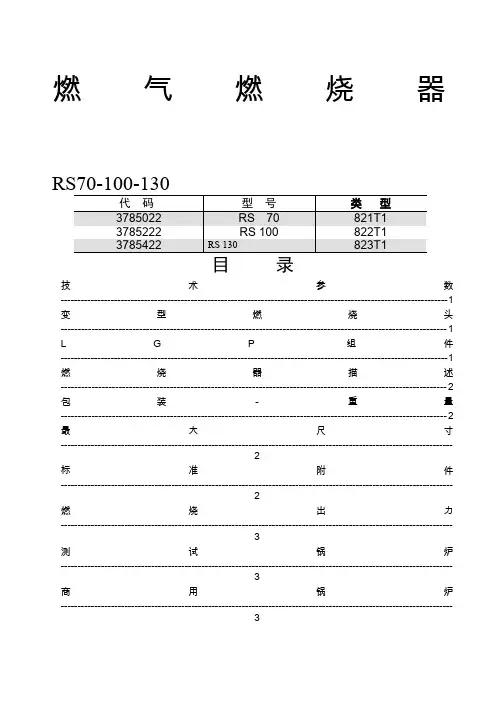
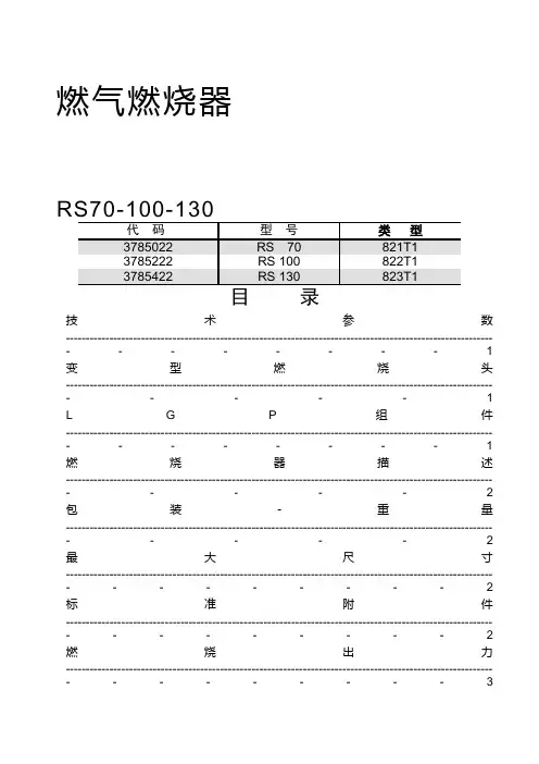
燃气燃烧器RS70-100-130目录技术参数--------------------------------------------------------------------------------------------------------------------1变型燃烧头-----------------------------------------------------------------------------------------------------------------1 L G P组件--------------------------------------------------------------------------------------------------------------------1燃烧器描述-----------------------------------------------------------------------------------------------------------------2包装-重量-----------------------------------------------------------------------------------------------------------------2最大尺寸---------------------------------------------------------------------------------------------------------------------2标准附件---------------------------------------------------------------------------------------------------------------------2燃烧出力---------------------------------------------------------------------------------------------------------------------3测试锅炉---------------------------------------------------------------------------------------------------------------------3商用锅炉---------------------------------------------------------------------------------------------------------------------3燃气压力---------------------------------------------------------------------------------------------------------------------4安装---------------------------------------------------------------------------------------------------------------------------5锅炉板------------------------------------------------------------------------------------------------------------------------5燃烧头长度------------------------------------------------------------------------------------------------------------------5燃烧器固定到锅炉上------------------------------------------------------------------------------------------------------5设定燃烧头------------------------------------------------------------------------------------------------------------------6阀门组------------------------------------------------------------------------------------------------------------------------7电气系统--------------------------------------------------------------------------------------------------------------------8点火前调整-----------------------------------------------------------------------------------------------------------------11伺服电机------------------------------------------------------------------------------------------------11燃烧器起动-----------------------------------------------------------------------------------------------------------------11燃烧器点火-----------------------------------------------------------------------------------------------------------------11燃烧器校准-----------------------------------------------------------------------------------------------------------------12 1-点火输出功率----------------------------------------------------------------------------------------------------------12 2-最大输出功率-------------------------------------------------------------------------------------------------------12 3-最小输出功率------------------------------------------------------------------------------------------------------134-中间输出功率---------------------------------------------------------------------------------------------------------13 5-空气压力开关---------------------------------------------------------------------------------------------------------14 6-最大燃气压力开关--------------------------------------------------------------------------------------------------14 7-最低燃气压力开关--------------------------------------------------------------------------------------------------14火焰有无检查------------------------------------------------------------------------------------------------------------14燃烧器运行----------------------------------------------------------------------------------------------------------------15最终检查------------------------------------------------------------------------------------------------------------------16维护-------------------------------------------------------------------------------------------------------------------------16状态/L E D面板-----------------------------------------------------------------------------------------------------------17故障-可能的原因-排障建议-----------------------------------------------------------------------------------------18本文中所提到的图形如下标识:1)(A)=图A的第1部分,与文本同页1)(A)p.4=图A的第1部分,页号4技术参数2)测试点16)(A)p.2处的压力,燃烧室压力为零,燃气环2)(B)p.7开启,燃烧器输出功率最大。
燃气燃烧器目录技术参数-------------------------------------------------------------------------------------------------------------------- 1 变型燃烧头----------------------------------------------------------------------------------------------------------------- 1 L G P组件-------------------------------------------------------------------------------------------------------------------- 1 燃烧器描述----------------------------------------------------------------------------------------------------------------- 2 包装-重量----------------------------------------------------------------------------------------------------------------- 2 最大尺寸--------------------------------------------------------------------------------------------------------------------- 2 标准附件--------------------------------------------------------------------------------------------------------------------- 2 燃烧出力--------------------------------------------------------------------------------------------------------------------- 3测试锅炉--------------------------------------------------------------------------------------------------------------------- 3 商用锅炉--------------------------------------------------------------------------------------------------------------------- 3 燃气压力--------------------------------------------------------------------------------------------------------------------- 4 安装--------------------------------------------------------------------------------------------------------------------------- 5 锅炉板------------------------------------------------------------------------------------------------------------------------ 5 燃烧头长度------------------------------------------------------------------------------------------------------------------ 5 燃烧器固定到锅炉上------------------------------------------------------------------------------------------------------5 设定燃烧头------------------------------------------------------------------------------------------------------------------ 6 阀门组------------------------------------------------------------------------------------------------------------------------7 电气系统--------------------------------------------------------------------------------------------------------------------8 点火前调整-----------------------------------------------------------------------------------------------------------------1 1 伺服电机------------------------------------------------------------------------------------------------11 燃烧器起动-----------------------------------------------------------------------------------------------------------------1 1 燃烧器点火-----------------------------------------------------------------------------------------------------------------1 1燃烧器校准-----------------------------------------------------------------------------------------------------------------1 2 1-点火输出功率----------------------------------------------------------------------------------------------------------122-最大输出功率-------------------------------------------------------------------------------------------------------12 3-最小输出功率------------------------------------------------------------------------------------------------------13 4-中间输出功率---------------------------------------------------------------------------------------------------------13 5-空气压力开关---------------------------------------------------------------------------------------------------------14 6-最大燃气压力开关--------------------------------------------------------------------------------------------------14 7-最低燃气压力开关--------------------------------------------------------------------------------------------------14 火焰有无检查------------------------------------------------------------------------------------------------------------1 4 燃烧器运行----------------------------------------------------------------------------------------------------------------1 5 最终检查------------------------------------------------------------------------------------------------------------------1 6 维护-------------------------------------------------------------------------------------------------------------------------1 6 状态/L E D面板-----------------------------------------------------------------------------------------------------------17故障-可能的原因-排障建议-----------------------------------------------------------------------------------------18 本文中所提到的图形如下标识:1)(A)=图A的第1部分,与文本同页1)(A)p.4=图A的第1部分,页号4技术参数1) 参考条件:环境温度20℃,表压1000mbar,海拔100m2) 测试点16)(A)p.2处的压力,燃烧室压力为零,燃气环2)(B)p.7开启,燃烧器输出功率最大。
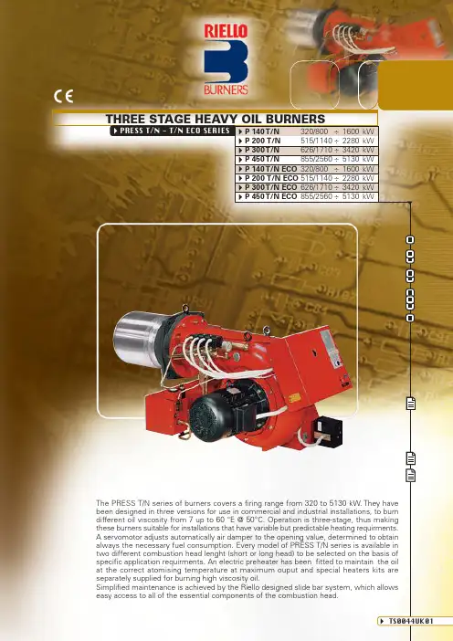
The PRESS T/N series of burners covers a firing range from 320 to 5130 kW. They have been designed in three versions for use in commercial and industrial installations, to burn different oil viscosity from 7 up to 60 °E @ 50°C. Operation is three-stage, thus making these burners suitable for installations that have variable but predictable heating requirments.A servomotor adjusts automatically air damper to the opening value, determined to obtain always the necessary fuel consumption. Every model of PRESS T/N series is available in two different combustion head lenght (short or long head) to be selected on the basis of specific application requirments. An electric preheater has been fitted to maintain the oil at the correct atomising temperature at maximum ouput and special heaters kits are separately supplied for burning high viscosity oil.Simplified maintenance is achieved by the Riello designed slide bar system, which allows easy access to all of the essential components of the combustion head.PRESS T/N - T/N ECO SERIESTHREE STAGE HEAVY OIL BURNERSP 140 T/N 320/800÷1600kW P 200 T/N 515/1140÷2280kW P 300 T/N 626/1710÷3420kW P 450 T/N 855/2560÷5130kW P 140 T/N ECO 320/800÷1600kW P 200 T/N ECO 515/1140÷2280kW P 300 T/N ECO 626/1710÷3420kW P 450 T/N ECO 855/2560÷5130kWSince the Company is constantly engaged in the production improvement, the aesthetic and dimensional features,the technical data, the equipment and the accessories can be changed.This document contains confidential and proprietary information of RIELLO S.p.A. Unless authorised, this information shall not be divulged, nor duplicated in whole or in part.(*) For High viscosity versions only.Reference conditions:Ambient temperature: 20°CBarometric pressure: 1000 mbar Altitude: 100 m a.s.l.Noise measured at a distance of 1 mFIRING RATESkW500100015002000250030003500400045005000Useful working field for choosing the burnerT est conditions conforming to EN 267:Temperature: 20°C Pressure: 1013.5 mbar Altitude: 100 m a.s.l.h P a (m b a r )m m H 2O101214161810012014016018002468020406080P 140 T/N (ECO)P 300 T/N (ECO)P 450 T/N (ECO)P 200 T/N (ECO)05500prEN 267 > 100 Kg/hThe 3 stage burner series can burn different heavy oil type from 50 up to 450 cSt @ 50°C (7 up to 60°E @ 50°C).For different viscosity levels Riello recommends 3 different configurations:1)Press T/N version for viscosity up to 50 cST (7°E) @ (50°C:basic version with 2800 rmp oil pump installed directly on fan motor shaft2)Press T/N version for viscosity up to 200 cST (25°E) @ 50°C:as basic version + heavy oil cartridges factory installed on nozzles, pump and valves group 3)Press T /N ECO version for viscosity up to 450 Cst (60°E) @ 50°C:- with separate 1400 rpm low speed pump- heavy oil cartridges factory installed on nozzles, pump and valves group- pipes heating cable factory installedSELECTING THE FUEL SUPPL Y LINESThe fuel feed must be completed with the safety devices required by the local norms.IMPORTANT NOTES- The oil could easily flow through the pipes if those are properly sized, protected and heated (by electricity, steam or hot water)- For starting-up: after excluding the burner by the shutter valves, let the oil flow into the supply ring up to reach the required circulation; after that open the valves and supply normally the burner.- The forwarding pump should have at least a double capacity than that one of the burner. For several burners supplied through the same ring supply line, the forwarding pump should have a capacity of approximatively 30% more than the sum of the single burner output.FBRSB2RS2PP2VR2VCBVG P1VGZTMVSTET MM PS TF1TF1Tburners of PRESS T/N seriesWith three stage operation, the PRESS T/N burners can follow the temperature load requested by the system.A ratio between maximum and minimum working output of 3:1 is reached, thank to the servomotor:the air delivery is proportional to required output.On three stage operation, the burner gradually adjusts output to the requested level, by varyingbetween the three pre-set levels (see picture A).ADJUSTMENTBURNER OPERATION MODEO u t p u tC o n t r o l l e d v a r i a b l ePicture AIn the table below operation, maximum output and fuel deliveries of the burners are shown.P 140 T/N (ECO)P 200 T/N (ECO)P 300 T/N (ECO)P 450 T/N (ECO)Max output(kW)1st 2nd 3rd 1st 2nd 3rd 1st 2nd 3rd 1st 2nd 3rd 5361060159576315162279114022803420171034205130Stage479314067133200100200300150300450Max delivery(kg/h)Three stage operationbar°C timetimeModelmaxAll PRESS T/N series burners are fitted with a new microprocessor control panel for the supervision during intermittent operation.For helping the commissioning and maintenance work, there are two main elements:The lock-out reset button is the central operating element for resetting the burner control and for activating / deactivating the diagnostic functions.The multi-color LED is the central indication element for visual diagnosis and interface diagnosis.Both elements are located under the transparent cover of lock-out reset button, as showed below.There are two diagnostic choices, for indication of operation and diagnosis of fault cause:- interface diagnosis :by the interface adapter and a PC with dedicated s o f t w a r e o r b y a predisposed flue gas analyzer (see paragraph accessories).SwitchIndication of operation :In normal operation, the various statues are indicated in the form of colour codes according to the table below.The interface diagnosis (with adapter) can be activated by pressing the lock-out button for > 3 seconds.LED offDiagnosis of fault causes:After lock-out has occurred, the red signal lamp is steady on. In this status, the visual fault diagnosis according to the error code table can be activated by pressing the lock-out reset button for > 3 seconds.The interface diagnosis (with adapter) can be activated by pressing again the lock-out button for > 3seconds.The blinkers of red LED are a signal with this sequence:(e.g. signal with n ° 3 blinks – faulty air pressure monitor)LED off3 sec.3 sec.3 sec.Error code tablePossible cause of faultThe flame does not stabilise at the end of the safety time:- faulty photocell- faulty or soiled oil valves - faulty ignition transformer - poor burner regulation Not usedLight in the chamber before firing Loss of flame during operations:- poor burner regulation - faulty or soiled oil valvesFaulty thermostat for oil permissive signal Heating resistances blown Wiring error or internal faultBlink codeSTART UP CYCLEStart up procedure is referred to a three stage operation0s The burner begins the start-up cycle: thermostat TL closes.XsThe motor starts running. Factory setting: 20s. T his time determines the heavy oil temperature at ignition.It can be adjusted, according to the fuel’s viscosity, by the timer. T he adiacent diagram shows the suggested settings.3s Ignition transformer turns on.25s Solenoid security valve VS and 1st stage valve VF1 open: 1st stage flame.30s Lock out takes place if flame is not revealed by the photocell. Otherwise ignition transformer switches off.32s 2nd stage solenoid valve VF2 opens.39s 3rd stage solenoid valve VF3 opens.For alternatives start-up procedures, consult the instructions’ manual.P 140 T/N - P 200 T/N - P 300 T/N - P 450 T/NLock-outNormal TLtime (s)MVF1VF2VF3x12252VS 7Direct start-up version P 140-200-300 T/NStar delta start-up version P 300-450 T/NMB- Burner terminal boardL1, L2, L4- Lead section (see table A)TS- Safety thermostatS- External lock-out signalTL- Threshold thermostatTR- High/low flame setting thermostatT6A- 6A fuseF1, F2, F3- Fuse (see table A)I1- Manual switchSA- High temperature oil alarmT2- 2nd stage load control systemT3- 3rd stage load control systemPS- Lock-out reset buttonMB- Burner terminal boardL2, L3,L4, H- Lead section (see table A)TS- Safety thermostatS, S2- External lock-out signalTL- Threshold thermostatTR- High/low flame setting thermostatT6A- 6A fuseF1, F2, F3- Fuse (see table A)MA- Star delta starterI1- Manual switchSA- High temperature oil alarmT3- 3rd stage load control systemT2- 2nd stage load control systemPS- Lock-out reset buttonThe following table shows thesupply lead sections and thetype of fuse to be used.T/N ECO VERSIONST/N ECO VERSIONSL1P L2PL3PL1 L2 L3NLF3L4L1R N4AEMISSIONSThe emission data has been measured in the various models at maximum output, according to EN 267 standard.m g /k W hP 140 T/N (ECO)P 200 T/N (ECO)P 300 T/N (ECO)P 450 T/N (ECO)NOx EMISSIONSm g /k W h50100150200250CO EMISSIONSd B (A )20406080100NOISE EMISSIONSP 140 T/N (ECO)P 200 T/N (ECO)P 300 T/N (ECO)P 450 T/N (ECO)P 140 T/N (ECO)P 200 T/N (ECO)P 300 T/N (ECO)P 450 T/N (ECO)PRESS T/N(1) Length with extended combustion headINSTALLATION DESCRIPTIONBURNER SETTINGHYDRAULIC AND ELECTRICAL CONNECTIONS AND START -UP All the burners have slide bars, for easier installation and maintenance.After drilling the boilerplate, using the supplied gasket as a template, dismantle the blast tube from the burner and fix it to the boiler.Adjust the combustion head.Refit the burner casing to the slide bars.Install the nozzle, choosing this on the basis of the maximum boiler output and following the diagrams included in the burner instruction handbook.Check the position of the electrodes.Close the burner, sliding it up to the flange, keeping it slightly raised to avoid the flame stability disk rubbing against the blast tube.The burners are supplied for connection to two pipes fuel supply system.Connect the ends of the flexible pipes to the suction and return pipework using the supplied nipples.Make the electrical connections to the burner following the wiring diagrams included in the instruction handbook.Prime the pump by turning the motor (after checking rotation direction if it is a three phase motor).On start up, check:- Pressure pump and valve unit regulator (to max. and min.)- Combustion quality, in terms of unburned substances and excess air.Installation, start up and maintenance must be carried out by qualified and skilled personnel.All operations must be performed in accordance with the technical handbook supplied with the burner.BURNER ACCESSORIESNozzlesThe nozzles must be ordered separately. The following table shows the features and codes on the basis of the maximum required output.Nozzle codeRated delivery at 25 bar (kg/h)BurnerSpacer kitIf burner head penetration in the combustion chamber needs reducing, varying thickness spacers are available, as given in the following table.BurnerKit code300072230007233000751Spacers kit110110130Spacer thickness S (mm)P 300 T/N P 450 T/N P 140 T/N - P 200 T/N GPHAvailable for T/N and T/N ECO versionsSP 140 T/N 20,83,53043162P 140 T/N 23,843043172P 140 T/N26,84,53043182P 140 T/N - P 200 T/N 29,853043192P 140 T/N - P 200 T/N 32,75,53043202P 140 T/N - P 200 T/N 35,763043212P 140 T/N - P 200 T/N 38,76,53043222P 140 T/N - P 200 T/N 41,773043232P 140 T/N - P 200 T/N 44,67,53043242P 200 T/N - P 300 T/N 50,68,53043262P 200 T/N - P 300 T/N56,59,53043272P 200 T/N - P 300 T/N - P 450 T/N 62,510,53043302P 300 T/N - P 450 T/N 71,4123043322P 300 T/N - P 450 T/N 80,413,53043342P 300 T/N - P 450 T/N 92,315,53043372P 450 T/N 104,217,53043402P 450 T/N 116,119,53043432P 450 T/N 12821,53043452P 450 T/N 142,8243043472Nozzles type F80 - PL 60°NOTE: each burner needs N ° 3 nozzles.(*) according to EN 15036-1 standardSound proofing boxIf noise emissions need reducing, sound proofing hoods are available, as given in the following table.BurnerBox code30104043010376P 300 T/N - P 450 T/N P 140 T/N - P 200 T/N Sound proofing boxSelfcleaning filterFor cleaning heavy oil from dirty particles and impurities, it is equipped with a thermostatic heater for oil with 60°E viscosity at 50°C.T ypeFilter code3010022Ø=1”1/2 (65°E at 50°C)Filtering degree (μm)300Heaters and thermostatsT ype Heater/thermostat codeThermostatic heater with LED 3010060Heater3010061Thermostat (two-stage / regulable)3010062BurnerDegaser codeP 140 T/N - P 200 T/N 3000748P 300 T/N - P 450 T/N 3010012Degasing unitFilterWithout WithoutDegasing unitIt allows to recover heat in excess by discharge of the gas from the return circuit.BurnerKit codeHeavy oil kit3000721P 140 T/N - P 200 T/N - P 300 T/N - P 450 T/N Heavy oil kitEquipped with electrcal heaters, it permits the employment of PRESS T/N burners with fuel oil of max.°C.Box type C4/5C7Average noise reduction [dB(A)] (*)1010Burner supportFor easier maintenance, a mobile burner support has been designed, which means the burner can be dismantled without the need of forklift trucks.BurnerSupport code3000731Burner supportP 300 T/N - P 450 T/N P 140 T/N - P 200 T/N P 300 T/N - P 450 T/NHeavy oil precirculationBurnerCode30007493000750Heavy oil precirculation kitThis kit, used with oil with high viscosity, in maintains fuel circulation in the ol circuit for avoiding system stop at start up.PC interface kitTo connect the flame control panel to a personal computer for the transmission of operation, fault signals and detailed service information, an interface adapter with PC software are available.BurnerKit code3002719Interface adapterP 140 T/N - P 200 T/N - P 300 T/N - P 450 T/NA specific index guides your choice of burner from the various models available in the PRESS T /N series.Below there is a clear and detailed specification description of the product.SPECIFICATIONDESIGNATION OF SERIESAVAILABLE BURNER MODELSAsk specific code for “ECO” models.Other models are available on request.P 140 T/N (ECO)TC3/230-400/50230/50P 140T/N (ECO)TL 3/230-400/50230/50P 140 T/N (ECO)TC 3/220-380/60220/60P 140T/N (ECO)TL 3/220-380/60220/60P 200 T/N (ECO)TC 3/230-400/50230/50P 200T/N (ECO)TL 3/230-400/50230/50P 200 T/N (ECO)TC 3/220-380/60220/60P 200T/N (ECO)TL 3/220-380/60220/60P 300 T/N (ECO)TC 3/230-400/50230/50P 300T/N (ECO)TL3/230-400/50230/50P 300T/N (ECO)TC3/230/50230/50P 300 T/N (ECO)TL 3/230/50230/50P 300T/N (ECO)TC 3/400/50230/50P 300T/N (ECO)TL 3/400/50230/50P 450 T/N (ECO)TC 3/230/50230/50P 450T/N (ECO)TL 3/230/50230/50P 450 T/N (ECO)TC 3/400/50230/50P 450T/N (ECO)TL3/400/50230/50BASIC DESIGNATIONEXTENDED DESIGNATIONElectrical supply to the system :1/230/50 1 / 230V / 50Hz 3/230/50 3 / 230V / 50 Hz 3/400/503N / 400V / 50Hz 3/230-400/503/ 230V / 50 Hz - 3N / 400V / 50Hz 3/220-380/603/ 220V / 60 Hz - 3N / 380V / 60HzN Two stage N ECO Two stage with separate oil pump T/N Three stage T/N ECO Three stage with separate oil pump P/NModulatingP/N ECO Modulating with separate oil pumpEmission :… Class 1 EN267Head :TC Standard head TLExtended headSizeSeries : PRESSFlame control system :FS1Standard (1 stop every 24 h)FS2Continuous working (1 stop every 72 h)Auxiliary voltage :230/50230V / 50Hz 220/60220V / 60HzPR ESS 140T/N TC FS13/230-400/50230/50Operation :PRODUCT SPECIFICATIONBurner:Monoblock forced draught heavy oil burner, three stage operation, made up of:- Air suction circuit- Fan with forward curved blades- Air dampers for air setting controlled by a servomotor- Fan motor at 2850 rpm- Combustion head, fitted with:- stainless steel end cone, resistant to corrosion and high temperatures- ignition electrodes- flame stability disk- Gears pump for high pressure fuel supply, fitted with:- filter- pressure regulator- connections for installing a pressure gauge and vacuometer- internal by-pass for single pipe installation- Valve unit with a oil safety shut-off valve fitted in series with three valves controlling three-stage on the output circuit- Heavy oil kit cartridges (for T/N version viscosity 7°E @ 50°C and for T/N ECO version)- Pipes heating cable (T/N ECO version)- Oil pump motor at 1400 rpm (T/N ECO version)- Oil preheater- Servomotor for air damper regulation- Photocell for flame detection- Flame control panel- Flame inspection window- Slide bars for easier installation and maintenance- Protection filter against radio interference- IP 40 electric protection level.Conforming to:- 89/336/EEC directive (electromagnetic compatibility)- 73/23/EEC directive (low voltage)- EN 267 (liquid fuel burners).Standard equipment:- 2 flexible hoses for pipe connection- 2 nipples for flexible hoses- 1 thermal insulation screen- 4 screws for fixing the burner flange to the boiler- 3 nozzles- 2 extensions for bars (for long head version of P 300 T/N and P 450 T/N)- 5 wiring looms for fittings for electrical connections (7 for P 450 T/N version)- 1 star delta starter (only for P 450 T/N version)- Instruction handbook for installation, use and maintenance- Spare parts catalogue.Available accessories to be ordered separately:- Nozzles- Head lenght reduction kit (spacer)- Sound-proofing box- Burner support- Gas separator bottle- Selfcleaning filter- Heavy oil kit- Heavy oil precirculation kit- PC interface kit.RIELLOTel. ++39.0442630111 - Fax ++39.044221980Internet:-E-mail:**********************Since the Company is constantly engaged in the production improvement, the aesthetic and dimensional features, the technical data, the equipment and the accessories can be changed.This document contains confidential and proprietary information of RIELLO S.p.A.Unless authorised, this information shall not be divulged, nor duplicated in whole or in part.。
燃气燃烧器GULLIVER RS5代码型号类型T1 3761900 RS5 920目录1..燃烧器总述------------------------------------------------------11.1燃烧器附件--------------------------------------------------12..技术数据---------------------------------------------------------22.1技术数据-----------------------------------------------------2 2.2总体尺寸-----------------------------------------------------22.3工作范围-----------------------------------------------------33..安装--------------------------------------------------------------43.1锅炉安装-----------------------------------------------------43.2燃气供给-----------------------------------------------------43.3燃气管路------------------------------------------------------53.4探针-电极位置---------------------------------------------------53.5电气连接-----------------------------------------------------64..工作--------------------------------------------------------------74.1燃烧调节-----------------------------------------------------74.2燃烧检查-----------------------------------------------84.3燃烧器启动程序-------------------------------------------------84.4空气压力开关-----------------------------------------------------95.维护---------------------------------------------------------------96.故障及解决办法-------------------------------------------------101 燃烧器描述两段火燃气燃烧器1 – 压力开关2 – 连接阀门组的6孔插座3 – 带7孔插座的控制盒4 – 带锁定灯的复位按钮5 – 燃烧头组装件6 – 压力测点7 – 带绝缘垫的法兰8 – 风门调节组件9 – 风门开启马达◆燃烧器符合IP40,EN60529电保护等级◆CE标志指90/396/EEC;PIN燃气使用标准◆符合标准:EMC89/336/EEC,73/23/EEC,98/37/EEC,92/42/EEC.◆阀门组符合EN676.1.1 燃烧器附件带绝热石棉垫的法兰1个安装法兰用螺钉螺母4个法兰用螺钉螺母1套电容1个7针插头1个2 技术参数 2.1 技术参数类型920 T1 燃烧功率(1)160-330kW - 137,600-283,800kcal/h 热值: 8-12kWh/m 3=7,000-10,340Kcal/m 3 天然气 ( 2类 ) 压力: 最小20mbar —最大100mbar 电源 单相,230V ±10% 50Hz电机2A – 2750rpm – 289 rad/s 电容8uF 点火变压器 二级8Kv – 230V – 0.2A用电总功率0.43kW (1)参考条件:温度:15℃ - 大气压 1013mbar – 海拔高度 0m对于3类燃气(LPG)要应用备件:国家IT GB DE AT DK FR NL BE IE 燃气种类II2H3B/PII2H3PII2E3B /P II2H3B /P II2H3B /PII2Er3P I2L3B/P I2E(R)B,I3PII2H3PG20H 20 20 --- 20 20 --- --- --- 20 G25L --- --- --- --- --- --- 25 25 --- 气 压 G20 E --- --- 20 --- --- 20/25--- 20/25---2.2 外观尺寸2.3 燃烧范围炉膛背压mbar热功率实验锅炉:以上工作曲线是用符合DIN 4788和EN 676标准的锅炉测量的。
Installation and Operating Instruction SupplementUse in conjunction with the original technical literature supplied by Riello Riello BurnerGas or Oil-Fired Burnerfor use with Vitola200boilerHeating input83to300MBH24to88kWRiello BurnerIf theexactly,IMPORTANTRead and save these instructionsfor future reference.5265665v2.512/2009Safety,Installation and Warranty Requirements2Please ensure that this manual is read and understood before commencing installation.Failure to comply with the issues listed below and details printed in this manual can cause product/property damage ,severe personal injury ,and/or loss of life .Ensure all requirements below are understood and fulfilled (including detailed information found in manual subsections).Each of the following issues is very important and is discussed in detail in the boiler technical literature.Ensure that the installation complies fully and completely with all requirements set out in the boiler technical literature.H Licensed professional heating contractorThe installation,adjustment,service,and maintenance of this equipment must be performed by a licensed professional heating contractor."Please see section entitled “Important Regulatory and InstallationRequirements”.H Product documentationRead all applicable documentation before commencing installation.Store documentation near boiler in a readily accessible location for reference in the future by service personnel."For a listing of applicable literature,please see section entitled “Important Regulatory andInstallation Requirements”.H Advice to ownerOnce the installation work iscomplete,the heating contractor must familiarize the systemoperator/ultimate owner with all equipment,as well as safetyprecautions/requirements,shut-down procedure,and the need forprofessional service annually before the heating season begins.H Contaminated airAir contaminated by chemicals can cause by-products in the combustion process which are poisonous to inhabitants and destructive to Viessmann equipment.H Carbon monoxideImproper installation,adjustment,service and/or maintenance can cause flue products to flow into living space.Flue products contain poisonous carbon monoxide gas.H Fresh airThis equipment requires fresh air for safe operation and must be installed ensuring provisions for adequate combustion and ventilation air exist.H Equipment ventingNever operate boiler without an installed venting system .H WarrantyInformation contained in this and related product documentation must be read and followed.Failure to do so renders warranty null and void.5265665v 2.5Do not chlorine near the Never adequate air.AllContents3PageSafety Important Regulatory and Installation Requirements4....Set-upProduct Delivery 4.......................................................................Mounting Burner5......................................................................Burner Set-up -Gas 6.................................................................Burner Set-up -Oil10...................................................................Oil Cartridge Assembly 13...........................................................Burner Set-up -Gas and Oil13..................................................Start-up/AppendixStart-up Information 14................................................................Technical Data 15..........................................................................Wiring Diagram18.........................................................................Maintenance Record20...............................................................OperationLighting Instructions23...............................................................5265665v 2.5Safety4Take note of all symbols and notations intended to draw attention to potential hazards or important productinformation.Set-up5Installation1.Remove burner from carton.The universal mounting flange has been installed on the burner at the factory.2.Mount burner as shown in Figs.1and 2.5265665v 2.5Fig.1Installing burnerFig.2Securing burner flange to combustion chamberdoorSet-up6InstallationThe gas train may be mounted on the left or on the right side of burner.G200burners have a ½”NPT female gas connection.G400burners have a ¾”NPT female gas connection.Gas trainNG flow pressure:min. 4.0”w.c.max.10.5”w.c.LP flow pressure:min.8.0”w.c.max.13.0“w.c.Legend (Fig.3)Gas supply and gas flow direction Gas shut-off valve (field supplied)Gas supply pressure test point (field supplied)Gas train pipe diameter(s)Burner G200½”NPT Burner G400¾”NPTMaxitrol RV52with RV5210-13(brown spring 1.0to 3.5”w.c.)gas appliance pressure regulator Honeywell gas solenoid valve V8295N.C.(24V operated)Dungs MVD-LE model 200G200=MVD-LE 205/6(24V)G400=MVD-LE 207/6(24V)Gas burner manifold test pointGas piping pressure testThe burner and its gas connection must be leak-tested before placing theboiler/burner combination in operation.The burner and its individual shut-off valve must be disconnected from the gas supply piping system during any pressure testing of that system atpressures in excess of 0.5psig/3.5kPa.Unions and manifold have been factory-tested.Leak test must be repeated during initial operation of burner by heating contractor.Never check for gas leaks with an open e approved spray liquid or soap water solution for bubble test.5265665v 2.5IMPORTANTFig.3Gas train Field Supplied Viessmann Supplied"Set-up7Flow adjustment cap Pan head screwSealing cap/adjustment cap toolBurner manifold gas pressure adjustmentThe burner manifold gas pressuresettings must be performed using the RV52gas appliance regulator only .In the event of low gas supply pressure,increase gas supply pressure using the RV52gas regulator to required minimum gas supply pressure.Operating and Installation Instructions for gas train components (supplied)No preliminary adjustments required for Honeywell V8295N.C.gas solenoid valve.Adjustment steps1.Attach manometer to burner manifoldtest point (combustion head ).2.Start up burner and observe.3.Wait until burner has stabilized to adjust burner manifold pressure using the RV52gas appliance regulator,and set to required burner manifold pressure setting.Use factory default settings (pages 15and 16)as starting point only.4.To adjust the initial lift gas pressure remove sealing cap,exposing the lift adjustment knob,turn over cap,adjust knob to “+”to increase the start pressure and set to approx.0.7to 0.9“w.c.(manifold pressure).Factory default setting is set to 100%full flow.5.Restart appliance at least three times to finalize gas manifold setting and to determine a smooth ignition.6.If burner fails to ignite or ignition is delayed or hard,one or more of the following corrective actions may be required:H Adjust initial gas pressure settingon Dungs gas valve.H Ignition electrode and/or ionization (flame)rod is not set withinspecified range,adjust setting by referring to original Installation Instructions of Riello burner.5265665v 2.5Fig.4MVD-LE valve,sideviewFig.5MVD-LE valve,top viewIMPORTANTIMPORTANTIMPORTANTSet-up8Verifying input of gas boilersNatural gas burners must have gas input clocked using the gas meter.Ensure there is no gas flowing through the meter other than to the gas-fired boiler being checked.See pages 15and 16for gas flow rate and values for time (in seconds)for clocking gas meter.Clock at least 10revolutions on a one ft 3gas meter dial and divide time by 10.The value arrived at should be the same as shown on pages 15and 16.If necessary,manifold pressure must be adjusted to make sure burner is firing at nominal input.Do not exceed gas input stated on rating plate.Turn adjustment screw on gas pressure regulator (RV52)clockwise to increase gas flow,and counterclockwise to decrease gas flow (as per instructions on the previous page).If checking gas input with a manometer only use manifold pressures given in manual as a starting point,and use combustion instruments to ensure safe and efficient combustion values.Be sure to turn gas off before attaching or removing pressure taps.All plugs removed for the purpose of gas pressure measurements must be replaced and leak-tested after Replacement of 24V gas valveUse only replacement gas valves from Viessmann Manufacturing.The 24VAC Dungs ¾”MVD-LE 207/6and ½”MVD-LE 205/6direct spark valves are special valves designed to operate at the low manifold pressures required by the Riello burner for both natural and propane gas.Do not use other gas valve unless specified by Viessmann.Field measured combustion resultsUse the combustion data label packed with the gas burner to record fieldmeasured combustion results and affix label to gas burner.Adjustment data tag ANSI Z21-17b-1994Input:C.F.H.Manifold pressure Air damper Air/gas ratio No.Flue gas temp.O 2level:%CO 2level:ppm DateCompleted by Installing contractorIt is necessary to follow all safety information in the Riello technical literature as well as all other OEM component instructions shipped with this manual.The Viessmann factory settings are an initial guide to be verified or changed by the installer based on field measured combustion results.The burner settings arrived at during field measurements may be different from the generalizedconversion burner settings given in the Riello technical literature.5265665v 2.5IMPORTANTEach Riello manifold gas valve,IMPORTANTSet-up9Summary of changes to original Rielloburner Note the following constructiondifferences between the general Riello conversion burner and Riello burnersupplied for use on the Vitola boiler.N200and P200burners for use with Vitola 200VB2-18to VB2-40The 40-(N,P)200gas burners when supplied by Viessmann for VB2-18and -22are constructedwith drawer assembly diaphragm installed in the combustion head assembly for natural gas andpropane.SleeveDrawer assembly diaphragm OrificeThe main gas orifice for natural gas is changed from the 2.0mm orificenormally supplied with a 40-(N,P)200aftermarket conversion burner to that stated in the table below.The differences in orifice size for the VB2-18,-22cause the manifoldpressure adjustment information in the Riello 40-(N,P)200manual to be not e the manifold pressures in this manual as a starting point for burner adjustment for the VB2-18,-22.Do not change orifice,diaphragm or sleeve-combination.Contact the Viessmann Technical Department.Burner Model Model No.Boiler G200VB2-18G200VB2-22G200VB2-33G200VB2-40OrificeLP1.3 1.3 1.3 1.3SleeveNG n.a.installed installed n.a.LPinstalled installed installedinstalledDiaphragmNG installed installed n.a.n.a.LPinstalledinstalledn.a.n.a.n.a.=not applicable5265665v 2.5IMPORTANTH:15.8mm W:19.5mmN88mm 19m mSet-up10The oil burner is provided with its own oil filter and built-in flow check valve.The flow check valve is located in the return,and a manual shut-off is located in the supply.One-pipe systems1.Connect as shown in Fig.6.5265665v 2.5Fig.6Connection to a one-pipesystemSet-up112.Mount filter support bracket either on the side of the boiler (Fig.7)or on the front of the boiler (Fig.8).3.Mount filter and check valve assembly to mounting bracket (Fig.9).Filter is disposable type and must be replaced with the filter cartridge supplied by Viessmann.5265665v 2.5Fig.7Side-mounting support bracketFig.8Front-mounting supportbracketFig.9Mounting filter and check valveassemblySet-up12oil line from tankto oil pump on burner from oil pump on burner recirculation to filter4.Connect flexible oil lines to the filter check valve assembly.See Fig.10.Red:supply (connection with the red manual valve)Blue:return (connection with the check valve).The Riello burner shipped by Viessmann comes with the bypass plug alreadyinstalled,ready for two-pipe connection.For a one-pipe system (gravity system where the oil tank is above the burner)use the copper tee provided.This tee converts the two-pipe system to a one-pipe system.The oil not used by the pump recirculates into the supply line.Pipe sealant must be used on the threaded ends of the flare fittings which join the copper tee to the filter check valve assembly .5.Install tee as shown in Fig.11.5265665v 2.5Fig.10Connect oil supply and returnlinesFig.11Converting two-pipe system to one-pipe systemSet-up131.Check that all surfaces are clean before installing new O-ring supplied with replacement filter cartridge.2.Set O-ring in place and mount new filter cartridge.3.Attach clear plastic cup and tighten brass nut.Never tighten brass nut with a tool;hand tighten only.Cap and O-ring mightdeform and leak air.The flare adaptors are tapped 3/8”BSP (British straight pipe)at the factory.Replacement flare adaptors must be ordered from Viessmann.Do not use 3/8”NPT flare adaptor as replacement.Burner Set-up -Gas and OilRefer to Riello instructions for adequatefuel supply pipe sizing and sequence of burner operation.Ensure an adequate supply of fresh combustion and ventilation air for safe operation.Refer to codes mentioned on page 4.Electrical connections1.Run the plug-in connector cable of the Vitotronic control down behind the front panel of the boiler and out through the wire strain relief as per the boiler installation instructions (Electrical Connections).2.Connect the female plug of the burner to the male plug of the Vitotronic control.See Fig.13.Installation Instructions Riello gas or oil burner5265665v 2.5Fig.12Oil cartridge assemblyIMPORTANTIMPORTANTWhen mounted,cup.Check IMPORTANTFig.13The quick-connect plug-insystemStart-up Information14Boiler start-upStart-up/Service Instructionsof boiler,as well as literature of burner,burner test sheet and control literature.Combustion analysisThis gas or oil burner requires combustion measurements to beperformed at the final installation site by a licensed heating contractor toverify factory settings,or to be used as a guide in changing burner settings to suit local conditions.Examples of local conditions which influence combustion results include:weather conditions,length of horizontal vent pipe,diameter and height of the chimney,side wall venting (power vent),altitude above sea level,quality and heating value of gas or oil used,maximum number of other fuel burning appliances running at the same time.These conditions affect the burnerset-up.The burner must be adjusted for acceptable combustion results under local conditions of the installation.When the boiler is fired for the first time,the ceramic fiber insulation at the back of the combustion chamber door will require ½to 1hour of firing time to “cure”.An odor may occur during this time.Final measurements of CO must be done only after the “cure”is complete.Combustion measurements (CO 2,stack temperature,draft and CO)are taken in the flue pipe between boiler and barometric draft regulator beforedilution air (see the installation manual).Overfire draft is measured at thecombustion chamber observation port opening.The expected CO 2products of combustion are printed below.These values are based on average results -slightly higher or lower values may be suitable depending on installation conditions.Fuel NG LP Oil CO 29.5to 10.2%10.0to 11.5%11.0to 13.0%The CO concentration should be asshown on the Viessmann quality control burner test results.If the COconcentration is above 50ppm,then measures should be taken to decrease concentration to a value below 50ppm.Steps to be taken include:ensuring sufficient supply of combustion air,adjusting air gate settings,ensuring chimney and vent are correct and meet safety codes,verifying boiler input and burner settings,replacing any defective part on burner,contactingmanufacturer’s technical sales representative for assistance.5265665v 2.5IMPORTANTTest port for combustion analysis equipmentDO NOT CRANKCASE OIL CONTAINING Do not controls.DO NOT BURNER ACCUMULATED,Appendix15Natural gasThe above specifications are for 0-2000ft.above sea level.Burner test resultsThe indicated values for manifold and air gate settings are the result of production line testing under ideal conditions.Final burner adjustment to suit local field conditions is necessary for safe operation.Observe the stated minimum and maximum supply gas pressures.Exposing the burner gas train to supply pressures other than the stated values can cause unsafe conditions.Viessmann strongly recommends the installation of an approved type CO detector in the vicinity of any gas burning equipment.Observe national and/or local code requirements.If in doubt consult your local gas company.Verification of resultsThe burner adjustment values indicated serve as a starting point bustion results must be field verified using properly calibratedBacharach or equivalent instruments.Each burner is certified for one input only.Do not overfire or underfire burner.Technical dataFuel natural gas ...........................................Averageheating value 1000MBH/ft 3...................Inlet gas pressuremin.4.0”w.c............max.10.5”w.c.Draft regulatorVB2-18to -40MG16”...........................VB2-50to -63MG17”...........................Overfire draft +0.01”w.c......................Max.breeching draft -0.02”w.c...........INPUT =3600/T x 1000where T =TIME (sec.)for 1ft 3natural gas INPUT =(3600x 0.01x 1000x 35.31)/T where T =TIME (sec.)for 0.01m 3natural gas5265665v 2.5Do not Factory changed IMPORTANTAppendix16Liquid propaneThe above specifications are for 0-2000ft.above sea level.Burner test resultsThe indicated values for manifold and air gate settings are the result of production line testing under ideal conditions.Final burner adjustment to suit local field conditions is necessary for safe operation.Observe the stated minimum and maximum supply gas pressures.Exposing the burner gas train to supply pressures other than the stated values can cause unsafe conditions.Viessmann strongly recommends the installation of an approved type CO detector in the vicinity of any gas burning equipment.Observe national and/or local code requirements.If in doubt consult your local LP company.Verification of resultsThe burner adjustment values indicated serve as a starting point bustion results must be field verified using properly calibratedBacharach or equivalent instruments.Each burner is certified for one input only.Do not overfire or underfire burner.Technical dataFuel propane gas .........................................Averageheating value 2500MBH/ft 3...................Inlet gas pressuremin.8”w.c............max.13”w.c.Draft regulatorVB2-18to -40MG16”...............VB2-50to -63MG17”...............Overfire draft +0.01”w.c....................Max.breeching draft -0.02”w.c......INPUT =3600/T x 2500where T =TIME (sec.)for 1ft 3propane gas INPUT =(3600x 0.01x 2500x 35.31)/T where T =TIME (sec.)for 0.01m 3propane gas5265665v 2.5Do not Factory changed IMPORTANTAppendixFig.14Air tube insertion (VB2-18,-22,-33)a asemi-flange(VB2-40,-50,-63)17Fuel oil No.2In multiple-boiler installations,a booster pump may be required.F10burners for use with Vitola 200VB2-50,VB2-63The F10as supplied by Viessmann uses the 10”long tube and a specialturbulator disc and end cone unique to Viessmann.Order replacements from Viessmann only.5265665v 2.5IMPORTANTAppendix18Vitotronic boiler controlRiello burner120VAC,60Hz,2.5ABurner plug-in connector(male and female)Primary control connections;connect blue wire to the followingterminal on the control box:Fuel NG LP OilTerminal776Motorized air damper(gas burneronly)Low water cut-off(field supplied,if required)Heating system ON/OFF switch120VAC,installer must provide15A overcurrent protectionReceptacle(site)120VACInstall the boiler as described in itstechnical documentation beforeinstalling or operating the burner.120VAC is supplied to burner viaplug-in connector.Do not connectadditional120VAC to burner.If any of the original wires as suppliedwith the appliance must be replaced,replace with221°F/105°C rated or itsequivalent.Minimum size18AWG.5265665v2.5LWCOTurn offsupplyContactLabelwhencan causeAppendix191.Install blocked vent switch(see enclosed FieldControls WMO-1Installation Instructions).2.Run BX cable (armored cable)or any other approved wire (required by local authorities having jurisdiction)from WMO-1switch to burner e nominal ½”electrical knockout provided on Riello plate forconnectors.If necessary,relocate wiring harness strain relief to other electrical opening provided.3.Disconnect black wire (BK)of 7-poleplug from oil burner primary control base.4.Rewire (wire nut included)the black wire (BK)through WMO-1safety switch and back to terminal “L”of the oil burner primary control.52Legend BK Black BU Blue GN Green RD Red WHWhiteFor use Do not sidewallAppendix20Service binder1.File all Parts Lists,Operating and Service Instructions in the Service Binder.2.Install a protective hanging case near the boiler and store the Service Binder in this location.MaintenanceBefore each heating season begins,have the following service and maintenance done by a licensed,professional heating contractor:1.Boiler heat exchanger inspected and cleaned.2.Vent system inspected fordeterioration,leaks,corrosion,proper draft,and proper operation.Check vent system for compliance withlocal and national code requirements.Repair or replace as required.3.Burner checked and,if necessary,adjusted for proper combustion and operation.Check for adequate supply of fresh outside combustion and ventilation air.5265665v 2.5Neglecting maintenance operation.Appendix215265665v 2.5Appendix225 2 6 5 6 6 5 v 2 . 5OperationManual gas shutoffOpenClosedTO1.Set thermostat or other operating controlsetting.2.Turn off all electric power to the applianceis to be performed.3.Close main gas shut-off valve.23Viessmann Manufacturing Company Inc.750McMurray RoadWaterloo,Ontario •N2V 2G5•CanadaTel.(519)885-6300•Fax (519)885-0887www.viessmann.ca •*****************Viessmann Manufacturing Company (U.S.)Inc.45Access RoadWarwick,Rhode Island •02886•USATel.(401)732-0667•Fax (401)732-0590 •*********************24Conversion Table H “w.c.x 2.54=mbar H mbar x 0.394=“w.c.H kW x 3413=Btu H bar x 14.5=psigH kg x 0.289=USG (#2oil)H BHP x 9.8=kW H BHP x 33779=Btu H m x 3.28=ft.H m 3x 35.3=ft.3H kcal x 3968=BtuH Cal value NG =950-1050Btu/ft.3H Cal value LP =2450-2500Btu/ft.3H Motor kW x 1.31=Motor HPNG Natural Gas LP Liquid PropaneQuick Reference °C °F -40-40-35-31-25-13-20-4-180-16+3-14+7-12+10-10+14-9+16-8+18-7+19-6+21-5+23-4+25-3+27-2+28-1+300+32+1+34+2+36+3+37+4+39+5+41+6+43+7+45+8+46+9+48+10+50+12+54+14+57+16+61+18+64+20+68+25+77+30+86+35+95+40+104+50+122+60+140+70+158+80+176+90+194+100+212+110+2305265665v 2.5T e c h n i c a l i n f o r m a t i o n s u b j e c t t o c h a n g e w i t h o u t n o t i c e .。
2902967 (0)安装, 使用及维护说明书强制通风燃气燃烧器编码型号类型3761900RS5920 T1一段火运行29671中文目录1.燃烧器描述一段火强制通风燃气燃烧器.1.1燃烧器附件带绝热垫的法兰. . . . . . . . . . . . . . 1 将法兰安装到锅炉上的螺栓和螺母. . . . . . . . . . . . . .. 4法兰用螺栓螺母 . . . . . . . . . . . . . 1 7针插头 . . . . . . . . . . . . . . . . . . . . . . . . . . . . . . . . . .1马达启动电容. . . . . . . . . . . . . . . 11.燃烧器描述. . . . . . . . . . . . . . . . . . . . . . . 11.1燃烧器附件. . . . . . . . . . . . . . . . . . . . . . . 12.技术参数. . . . . . . . . . . . . . . . . . . . . . . . . 22.1技术参数. . . . . . . . . . . . . . . . . . . . . . . . . 22.2外观尺寸. . . . . . . . . . . . . . . . . . . . . . . . . 22.3工作范围. . . . . . . . . . . . . . . . . . . . . . . . . 33.安装. . . . . . . . . . . . . . . . . . . . . . . . . . . . 43.1锅炉安装. . . . . . . . . . . . . . . . . . . . . . . . . 43.2燃气阀组电气连接. . . . . . . . . . . . . . . . . . 43.3燃气管线. . . . . . . . . . . . . . . . . . . . . . . . . 53.4电极定位. . . . . . . . . . . . . . . . . . . . . . . . . 53.5电气连接. . . . . . . . . . . . . . . . . . . . . . . . .64.工作 . . . . . . . . . . . . . . . . . . . . . . . . . . . .74.1燃烧调节 . . . . . . . . . . . . . . . . . . . . . . . . .74.2燃烧头设置 . . . . . . . . . . . . . . . . . . . . . . .74.3风门挡板设置. . . . . . . . . . . . . . . . . . . . . .84.4燃烧检查 . . . . . . . . . . . . . . . . . . . . . . . . .84.5燃烧器启动程序. . . . . . . . . . . . . . . . . . . .94.6空气压力开关. . . . . . . . . . . . . . . . . . . . . .95.维护 . . . . . . . . . . . . . . . . . . . . . . . . . . . .96.故障 / 解决方法 . . . . . . . . . . . . . . . . . . . .101–压力开关2–燃气阀组6 孔插座 3–带 7孔插座的控制盒4–带锁定指示灯的复位按钮 5–燃烧头安装座6–压力测试点7–带绝热垫的法兰8–风门调整机构 9–风门伺服马达燃烧器保护等级为IP 40, EN 60529.CE 认证: 参照燃气应用标准 92/42/EEC; PIN 0085BM0114.燃烧器符合下列标准:EMC 89/336/EEC, 低电压 73/23/EEC, 机械 98/37/EEC 和效率 92/42/EEC.燃气阀组符合 EN 676.图. 1SW100129672中文2.技术参数2.1技术参数对燃用LPG 可选特殊附件.2.2外观尺寸类型920 T1燃烧器出力 (1)160–330 kW-137,600–283,800 kcal/h天然气 (品种 2)净热值:8–12 kWh/Nm 3=7000–10,340 kcal/Nm 3压力:min. 20 mbar-max.100 mbar电源 单相,230V ± 10% ~ 50Hz马达运行电流 2A -2750 rpm-289 rad/s马达启动电容8 μF点火变压器初级 230V / 0.2A –次级8 kV / 12 mA电功耗0.43 kW(1) 参考条件: 温度. 20°C - 大气压力 1013 mbar – 海拔 0 m .国家ITGBDE AT DK FRNLBEIE燃气种类II2H3B/P II2H3PII2E3B/PII2H3B/PII2H3B/PII2Er3P II2L3B/P I2E(R)B,I3P II2H3P 燃气压力G20H 2020–2020–––20G25L ––––––2525–G20E––20––20/25–20/25–29673中文2.3工作范围 (参照 EN 267)实验锅炉以上工作曲线是用符合 EN 676 标准的锅炉测量得到.商用锅炉如果锅炉是符合 EN 303 标准,且燃烧室尺寸与 EN 676图表所示相近时,则燃烧器与锅炉是匹配的. 如果锅炉不是符合 EN 303 标准,且燃烧室尺寸比 EN 676图表所示更小 ,请咨询生产厂家.燃气压力与燃烧器出力的关系在用热值为10kWh/m 3(8.570 kcal/m 3)的G20燃气和锅炉背压在0 mbar 进行检测时,燃烧器最大出力时燃烧器头部的压降为 9.9 mbar(M2, 参见 3.3, P. 5).130,000290,000kW燃烧器出力kcal/h2.40.80燃烧室压力 – m b a rD62311.6170,000210,000250,0004.03.2kW燃烧器出力kcal/h632燃烧头的燃气压力 – m b a rD6232475891029674中文3.安装燃烧器的安装必须符合当地法规和标准.3.1锅炉安装♦如有必要, 对绝热垫扩孔(3) (参见图. 3).♦ 用4个螺钉 (4) 和螺母 (2) 将法兰(5)安装到炉门(1)上,必须将绝热垫 (3) 放在中间,但应保持上部两颗螺钉中的一颗松动 (4) (参见图. 2).♦用螺钉 6将法兰 5固定到燃烧头上 紧固,拧紧松动的螺钉 4.注意.: 燃烧器具有可调的燃烧头长度 (A) (参见图. 4).总之, 要保证燃烧头完全穿过锅炉前墙.3.2燃气阀组电气连接燃气阀组连接电线可从左边或右边进入燃烧器,如所示.根据进入燃烧器的方向, 带压力测试点的电缆孔堵简易电缆孔堵 (2) 可能需要互换因此, 必须确认:电缆孔堵 (1)位置正确;气管位置应正确,以保证空气通畅关造成阻塞.注意如有必要,可将气管切到正确的长度图. 2SW1003212D46051图. 529675中文3.3燃气管线符合 EN 676的燃气阀组燃气阀组单独供货, 它的调整参考附带的说明书.3.4探针 - 点火电极定位, (参见图. 7)燃气阀组连接方式应用型号编码入口出口MBDLE 410 B013970549Rp 11/4法兰 3天然气 ≤ 200kW 和 LPG 160 – 330 kWMBDLE 412 B013970550Rp 11/4法兰 3天然气 ≤ 300 kW MBDLE 415 B013970558Rp 11/2法兰 3天然气> 300 kWD52091 –供气管2 –手动球阀 (3 –燃气压力表 (4 –过滤器5 –燃气压力开关6 –安全阀7 –稳压器8 –调节阀M1–供气压力测试点M2–阀组后压力测试点29676中文3.5电气连接S7003230V ~50Hz(230V - 0.5 A max.)风门伺服马达图. 8警告; 断开连接器., 移开所有组件后, 7针 地线 (H) 拧松螺钉 (A,)紧上螺钉(A).29677中文4.工作燃烧出力燃烧器点火应在低负荷状态下进行并不超过120kW.为了测量燃烧出力:–断开离子探针电缆上的连接插头(C ) (参见电气连接P. 6); 燃烧器点火并在安全时间 (3s)过后锁定 .–进行10 次点火并连续锁定.–从流量表中读出耗气量. 该耗气量应等于或小于以下数值: G20 (天然气 H) 为0.10 Nm 3 G25 (天然气 L)为0.10 Nm 3 G31 (LPG)为0.03 Nm 3.4.1燃烧调整(参见图. 9)根据燃烧器应用于锅炉上的效率标准92/42/EEC ,调试燃烧器必须参考锅炉的使用说明书, 这一工作包括调整烟气中的 CO 和 CO 2 含量,烟温及锅炉中的平均水温.要达到所需要的出力, 要选择正确的燃烧头设定值和风门设定值.燃烧器出厂时设定在最小出力.4.2燃烧头设定根据燃烧器的出力,通过顺时针和逆时针旋转 设定螺丝 (6) 来进行,直到标尺 (2) 上的刻度值与燃烧头座 (1)的外边缘对齐.在图9中的燃烧头的设定是对应于燃烧器出力为230 kW.可见燃烧头的设定值为 4,即 标尺上的刻度值与燃烧头座的外边缘对齐 .示例:燃烧器安装在 210 kW 的锅炉.考虑到锅炉效率为 90%,燃烧器出力应为 230 kW.如图所示,燃烧头应设在 刻度4.注意此图表仅供参考;为了获得较好的燃烧效果,建议可根据锅炉调整燃烧头的设定.kcal/hkW设定点D6235SW1004图. 929678中文拆卸燃烧头组件, (参见图. 9, P. 7)按下列顺序操作:拧下螺钉(7), 断开连接插头 (3 和 5), 拆下小管 (4) 并拧松螺钉 (10)后拆下燃烧头座(1).在拆卸时不要改变燃烧头的肘型弯座 的设定.重新安装燃烧头组件, (参见图. 9, P.7)注意-在安装燃烧头时, 拧紧螺钉 (7) (不要拧太紧); 然后用力矩扳手( 3 - 4 Nm )锁紧.-如上操作确保燃烧器在运行时螺钉处不会有燃气泄露.- 如压力测点 (11) 松动,应正确固定并确保燃烧头组件(1)外部的孔 (F)安装在正确的位置上.4.3风门设定, (参见图. 9, P.7)在拧松螺母 (9)后对调节螺钉进行调整(8).燃烧器停机时风门会自动关闭,除非烟囱处最大压降大于0.5 mbar.4.4燃烧状况检查建议根据燃气种类和下表来初步设定燃烧器:离子探针电流燃烧器正常运行时控制器所需最小离子探针电流为 5 µA.一般情况下离子探针电流会远大于该值, 故不必检查. 如需要检查时, 可打开离子探针连接插头 (C) (参见页 6)串入微安电流表, (参见图. 10).在首次点火时风门设定不应小于1.EN 676过量空气系数:最大输出λ ≤ 1.2–最小输出λ ≤ 1.3燃气最大CO 2含量(0 % O 2)设定CO 2 %CO mg/kWhNO x mg/kWh λ = 1.2λ = 1.3G 2011.79.79.0 ≤100≤170G 2511.59.58.8 ≤100 ≤170G 3014.011.610.7 ≤100 ≤230G 3113.711.410.5≤100≤230注意29679中文4.5燃烧器启动程序由控制盒上的信号灯指示燃烧器锁定(4, 图. 1, P .1).在燃烧器运行时火焰消失, 燃烧器在1秒内停机.4.6空气压力开关空气压力开关的调整应在燃烧器的上述调整工作完成后进行,此时应设在初始位置.当燃烧器工作在额定出力时, 缓慢顺时针加大设定值,直至燃烧器锁定.然后逆时针旋转刻度盘将设定值减少20%, 并检查燃烧器是否能正常启动.如燃烧器锁定,应再少量减少空气压力开关的设定值.燃烧器出厂时空气压力开关在初始位置.注意:作为标准条例, 空气压力开关调整要防止当空气压力达到设定的 80% 时排烟中的 CO 超过 1% (10,000 ppm).如要检查这一点,请在烟囱中插入烟气分析仪, 缓慢关闭风机的进气口 (例如用纸板) 并检查在排烟中的CO 超过 1%之前是否会锁定.5.维护燃烧器必须由授权的和有资格的技术人员按照当地法规和标准进行定期性的维护.维护对于燃烧器运行的可靠性是必要的,可避免燃料的过量消耗以及随之而来的污染.在进行维护清理之前,必须将系统的主电源开关关掉,以切断燃烧器的电源.基本的检查有:让燃烧器不间断地运行10分钟,按本说明书检查所有组件的设置 . 然后进行燃烧测试以检查以下各项: CO 2 (%)的含量 排烟温度 CO (ppm)的含量.A296710中文6.故障 / 可能的解决方法下表所示是造成启动故障或燃烧器非正常运行等问题的原因及相应的解决方法.故障通常会造成控制盒 (4, 图. 1, P. 1)复位按钮键中的锁定指示灯亮.当锁定灯亮时,只有按复位按钮燃烧器才会重新启动,此后如果燃烧器运行正常,锁定可以归因于偶然故障.如果继续锁定,一定要查找原因,并加以解决.燃烧器启动故障故障可能原因解决方法当启动温控器闭合时,燃烧器不启动.没有电源供应.检查7针插头中的L1-N 线之间的电压是否存在.检查保险丝的状况.检查安全温控器是否锁定 .没有燃气供应.检查手动球阀是否打开 .检查阀组是否打开并且是否有短路 .燃气压力开关不闭合.调整.控制盒中的连接错误.检查并连接插头.空气压力开关在运行位置.更换压力开关.风门挡板卡住.检查电气连接.风门没全关所以燃烧器不点火: 检查.在预吹扫及点火阶段时燃烧器运行正常,但3秒后锁定.火线与零线接反.重接.没有地线或接地不良.确保接地良好.离子探针接地,离子探针未与火焰接触,离子探针与控制盒连线断开,与地短路 .检查离子探针的位置,如有必要可按本说明书进行设置.重新电气连接.更换损坏的接线.燃烧器点火延迟点火电极位置不对.按本说明书所示进行调整.空气太多.按说明书所示进行调整.阀门开度太小,燃气量不够.调整.296711中文运行中故障燃烧器锁定: – 火焰消失– 探针接地– 空气压力开关断开燃烧器停机: – 燃气压力开关断开燃烧器在预吹扫后因火焰故障而锁定.电磁阀过气量较小.检查管网压力/按说明书所示调整电磁阀.电磁阀损坏.更换.点火脉动或失败.检查接头.按说明书所示检查电极的位置.管道空气没有排净.燃气管道放散.燃烧器在预吹扫时锁定.空气压力开关不切换.压力开关故障,更换.空气压力过低, (燃烧头调整不当).火焰出现.阀门故障: 更换.压力测试点 (11, 图. 9, p 7) 位置不对. 按说明书 p 7, 节 4.2调整好位置.燃烧器不锁定,重复启动.主燃气压力接近于最低燃气压力开关所限定的数值.阀门开启后燃气压力的突降,从而引起压力开关的暂时断开.阀门立刻关闭,燃烧器停机.压力又升高,压力开关再次闭合,重复点火周期,该过程没有休止地进行.减小最低燃气压力开关的设定值.故障可能原因解决方法。