[核磁共振波谱学讲义]第三章—NMR实验技术基础(4脉冲技术)
- 格式:docx
- 大小:114.40 KB
- 文档页数:9
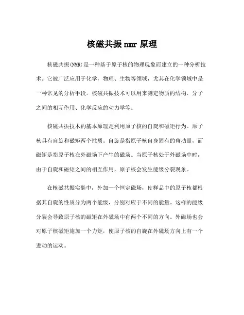
核磁共振nmr原理核磁共振(NMR)是一种基于原子核的物理现象而建立的一种分析技术。
它被广泛应用于化学、物理、生物等领域,尤其在化学领域中是一种常见的分析手段。
核磁共振技术可以用来测定物质的结构、分子之间的相互作用、化学反应的动力学等。
核磁共振技术的基本原理是利用原子核的自旋和磁矩行为。
原子核具有自旋和磁矩两个性质。
自旋是指原子核自身固有的角动量,而磁矩是指原子核在外磁场下产生的磁场。
当原子核处于外磁场中时,由于自旋和磁矩之间的相互作用,原子核会发生能级分裂现象。
在核磁共振实验中,外加一个恒定磁场,使样品中的原子核都根据其自旋的性质分为两个能级,分别对应于不同的能量。
这样的能级分裂会导致原子核的磁矩在外磁场中有两个不同的方向。
外磁场也会对原子核磁矩施加一个力矩,使原子核的自旋在外磁场方向上有一个进动的运动。
外磁场对原子核的能级分裂可以用精细结构常数来描述。
精细结构常数是一种度量原子核间相互作用的力度的物理量。
对于具有不同的原子核和不同的分子,精细结构常数会有所差异。
在核磁共振谱仪中,会通过调节外磁场的强度,并利用射频脉冲来激发样品中的原子核的进动。
射频脉冲产生的光谱信号会被检测,并通过数码计算机进行处理,最终得到核磁共振谱图。
核磁共振谱图是由峰表示的,每个峰对应于不同的分子结构。
通过核磁共振谱图,可以确定物质的结构、分子之间的相互作用以及化学反应的动力学等信息。
核磁共振技术的应用非常广泛。
在化学领域中,核磁共振技术可以用来确定有机化合物的结构,分析分子中的基团以及研究分子间的相互作用等。
在生物医学领域中,核磁共振技术可以用来研究蛋白质的折叠、细胞的内部结构以及代谢过程等。
此外,核磁共振技术还可以应用于材料科学、物理学等研究领域。
总的来说,核磁共振技术是一种基于原子核自旋和磁矩行为的分析手段。
通过调节外磁场的强度和应用射频脉冲,可以激发样品中的原子核,并通过测量光谱信号得到核磁共振谱图。
核磁共振技术在化学、物理、生物等领域中应用广泛,并为科学研究和实际应用提供了丰富的信息。
![[核磁共振共振波谱学讲义]第三章—NMR实验技术基础(2数据采集)](https://uimg.taocdn.com/fef85b9d51e79b8968022696.webp)
第三章 NMR 实验技术基础2 数据采集在现代脉冲Fourier 变换核磁谱仪上,核磁矩在一系列脉冲作用下产生横向磁化,横向磁化围绕外磁场进动并在探头的检测线圈中产生感生电流,经放大及ADC 数字化后记录下来。
这种时域信号称为FID(free-induction decay)或interferogram 。
前者专门指检测线圈中检测到的信号,后者既可指FID ,也可指多维谱中间接维中检测的信号。
数字化的FID 通常经Fourier 变换产生对应的频域信号即通常意义上的核磁共振谱,数字化处理是现代脉冲Fourier 变换核磁谱仪的一个典型特征。
a 采样定理在信号处理中最常用也最容易实现的是周期采样,即采样的时间间隔固定。
记时间间隔为∆t,有著名的采样定理:若一个连续时域信号的最高频率成分的频率不超过f c ,则周期采样信号系列S(k ∆t)能再现原信号的条件是:12∆t f c ≥ 通常称f tn =12∆为Nyquist frequency 换一种说法,采样频率不能低于信号最高频率的2倍。
(1) 满足采样定理时,原信号可由离散信号系列S(k ∆t)复原:s t S k t c ft k t n k ()()sin {()}=-=-∞∞∑∆∆2π 此处sin ()sin()c x x x =可检测到的最高信号频率为±采样频率/2,其间隔称为谱宽: SW f tn ==21∆ (2) 当信号频率超过Nyquist 频率时,将产生折叠现象(folding/aliasing),在频谱上表现为谱宽范围内的一个信号,如:当时域信号为复数系列时:两个频率成分νν02=+mf n a 与νa 在频谱上出现在同一位置. 前者的时域信号为:Ae Ae Ae Ae Ae Ae Ae Ae Ae i t i t i t i mf t i mf t i t i m i t i t n a n a a a ωθπνθπνθπνθππνθππνθπνθ++++++++======22222222220()这正是后者的时域信号,因而两种频率成分在时域的离散采样不可区分,也就是说,一个离散时间系列变换到的频谱具有有限带宽。
![[核磁共振波谱学讲义]第三章—NMR实验技术基础(3数据处理)](https://uimg.taocdn.com/0d415bc45ef7ba0d4a733bf8.webp)
第三章 NMR 实验技术基础3 数据处理现代脉冲Fourier 变换核磁谱仪以数字化形式记录FID ,意味着可以利用各种功能强大的数字处理技术。
a Fourier 变换定义时域信号与频域信号间的关系:这里s(t)同S(ω)形成Fourier 变换对,逆变换由下式定义:Fourier 变换是线性变换,即:此处c 为复常数以下是Fourier 变换的一些基本性质: similarity F s at a S a aS a {()}()()==11ων time shifting F s t eS e S i i {()}()()-==--τωνωτπντ2 frequency shifting F s t e S F s t e S i i {()}();{()}()--=-=-ωτπντωωνν00020 derivative theorem F d dt s t i S i S kk k k {()}()()()()==ωωπνν2convolution 两个函数s(t)及r(t)的卷积指:其Fourier 变换为:correlation 两个函数s(t)及r(t)的相关函数指:其Fourier 变换为: Parseval’s theorem s t dt S d S d ()()()222-∞∞-∞∞-∞∞⎰⎰⎰==ωωνν 实际上数字化信号的Fourier 变换是通过离散Fourier 变换来完成的,与连续Fourier 变换相比较,离散化引入新的周期性。
b FID 和线型核磁信号可以描述成:其Fourier 变换为:此处吸收线型A(ω)和色散线型D(ω)分别为:通称为Lorentz 线型Lorentz 吸收线型的半高宽∆ωλFWHH =20对采集到的FID 直接作Fourier 变换很难给出好的谱图,通常需要作一系列数据处理。
c 填零通常FID 的采集点数有限,这样频谱的数据分辨率不高,而且往往信号还未衰减到0,使得谱峰两边出现震荡现象。
NMR基础知识介绍NMR(核磁共振)是一种基于原子核的磁性性质进行分析的非常重要的技术。
它能够提供有关分子结构、化学环境、动力学和相互作用等方面的信息。
本文将介绍NMR的基础知识。
首先,了解什么是核磁共振很重要。
核磁共振是原子核固有的属性,当原子核中有未配对的核子时,它会在外部磁场的作用下产生自旋磁矩。
当这些原子核处于外部磁场中时,它们会以不同的能级分布方式依据其自旋状态。
核磁共振技术利用这些特性来研究样品中的原子核。
NMR的基本原理是基于核磁共振的共振现象。
当一定频率的电磁波通过样品时,只有在特定频率时,能够与样品中的原子核产生共振。
这个频率被称为拉莫尔频率。
当原子核共振时,它会从一个自旋状态跃迁到另一个自旋状态,吸收能量。
通过测量吸收能量,我们可以获得关于样品中原子核的信息。
在NMR实验中,我们用术语“化学位移”来描述化学环境对原子核共振频率的影响。
化学位移是一个无量纲量,通过与参考标准(通常为TMS)的比较来确定。
通过测量化学位移,可以确定不同原子的化学结构信息。
除了化学位移,J耦合也是NMR中常见的现象。
J耦合是指两个不同原子核之间的自旋相互作用。
这种相互作用可以提供关于化学结构和空间分布的重要信息。
通过分析J耦合常数,可以确定分子中的连接关系和官能团。
在NMR实验中,我们还常常使用“弛豫时间”来描述分子中核自旋状态的恢复速率。
共有两种类型的弛豫时间:横向弛豫时间(T2)和纵向弛豫时间(T1)。
横向弛豫时间指的是核自旋状态从高能级返回基态的恢复速率,而纵向弛豫时间指的是核自旋状态从基态恢复到高能级的速率。
在NMR实验中,可以使用不同的谱图来描述不同原子核信号。
最常用的是1H-NMR谱图,它提供了关于氢原子的信息。
此外,还有13C-NMR谱图、31P-NMR谱图等,它们可以提供关于碳和磷等原子核的信息。
最后,NMR技术在化学领域有许多应用。
它在有机化学中是一种非常强大的工具,可以用于确定化合物的结构、化学动力学和反应机理等方面。

第三章 NMR 实验技术基础1 NMR 仪器如图,现代超导核磁谱仪的主要组成部分包括:1. 超导磁体Magnet 包括Field Lock ,Shim Coils2. 探头Probe 内有RF Coils ,Gradient Coils3. 脉冲编程器及射频放大器4. 接收器5. 数据采集及处理计算机At the top of the schematic representation, you will find the superconducting magnet of the NMR spectrometer. The magnet produces the Bo field necessary for the NMR experiments. Immediately within the bore of the magnet are the shim coils for homogenizing the Bo field.Within the shim coils is the probe. The probe contains the RF coils for producing the B1 magnetic field necessary to rotate the spins. The RF coil also detects the signal from the spins within the sample. The sample is positioned within the RF coil of the probe. Some probes also contain a set of gradient coils. These coils produce a gradient in Bo along the X, Y , or Z axis. Gradient coils are used for for gradient enhanced spectroscopy, diffusion, and NMR microscopy experiments. The heart of the spectrometer is the computer. It controls all of the components of thespectrometer. The RF components under control of the computer are the RF frequency source and pulse programmer. The source produces a sine wave of the desired frequency. The pulse programmer sets the width, and in some cases the shape, of the RF pulses. The RF amplifier increases the pulses power from milli Watts to tens or hundreds of Watts. The computer alsocontrols the gradient pulse programmer which sets the shape and amplitude of gradient fields. The gradient amplifier increases the power of the gradient pulses to a level sufficient to drive the gradient coils. The operator of the spectrometer gives input to the computer through a console terminal with a mouse and keyboard. Some spectrometers also have a separate small interface for carrying out some of the more routine procedures on the spectrometer. A pulse sequence isselected and customized from the console terminal. The operator can see spectra on a video display located on the console and can make hard copies of spectra using a printer.1. 超导磁体MagnetMagnet主要要求:a 高磁场强度,分辨率与B0成正比,而灵敏度与B032成正比,故750MHz较600MHz的分辨率提高25%,而灵敏度提高40%b 高均匀性,目前可达10-9c 高稳定性The NMR magnet is one of the mostexpensive components of the nuclearmagnetic resonance spectrometer system.Most magnets are of the superconductingtype. A superconducting magnet has anelectromagnet made of superconductingwire. Superconducting wire has aresistance approximately equal to zerowhen it is cooled to a temperature close toabsolute zero (-273.15 C or 0 K) byemersing it in liquid helium. Once currentis caused to flow in the coil it willcontinue to flow for as long as the coil iskept at liquid helium temperatures.(Some losses do occur over time due to theinfinitesimally small resistance of the coil. These losses are on the order of a ppm of the main magnetic field per year.) The length of superconducting wire in the magnet is typically several miles. This wire is wound into a multi -turn solenoid or coil. The coil of wire and cryroshim coils are kept at a temperature of 4.2K by immersing it in liquid helium. The coil and liquid helium are kept in a large dewar. This dewar is typically surrounded by a liquid nitrogen (77.4K) dewar, which acts as a thermal buffer between the room temperature air (293K) and the liquid helium.The following image is an actual cut -away view of asuperconducting magnet. The magnet is supported by threelegs, and the concentric nitrogen and helium dewars aresupported by stacks coming out of the top of the magnet. Aroom temperature bore hole extends through the center of theassembly. The sample probe and shim coils are located withinthis bore hole. Also depicted in this picture is the liquidnitrogen level sensor, an electronic assembly for monitoringthe liquid nitrogen level.Going from the outside of the magnet to the inside, wesee a vacuum region followed by a liquid nitrogen reservoir.The vacuum region is filled with several layers of a reflectivemylar film. The function of the mylar is to reflect thermal photons, and thus diminish heat from entering the magnet. Within the inside wall of the liquid nitrogen reservoir, we see anothervacuum filled with some reflective mylar. The liquid helium reservoir comes next. This reservoir houses the superconducting solenoid or coil of wire.Taking a closer look at the solenoid it is clear to see the coil and the bore tube extending through the magnet.Field LockIn order to produce a high resolutionNMR spectrum of a sample, especially onewhich requires signal averaging or phasecycling, you need to have a temporallyconstant and spatially homogeneous magneticfield. Consistency of the Bo field over timewill be discussed here; homogeneity will bediscussed in the next section of this chapter.The field strength might vary over time due toaging of the magnet, movement of metal objects near the magnet, and temperature fluctuations. Here is an example of a one line NMR spectrum of cyclohexane recorded while the Bo magnetic field was drifting a very significant amount. The field lock can compensate for these variations.The field lock is a separate NMRspectrometer within your spectrometer. Thisspectrometer is typically tuned to thedeuterium NMR resonance frequency. Itconstantly monitors the resonance frequencyof the deuterium signal and makes minorchanges in the Bo magnetic field to keep theresonance frequency constant. The deuteriumsignal comes from the deuterium solvent usedto prepare the sample. The animation window contains plots of the deuterium resonance lock frequency, the small additional magnetic field used to correct the lock frequency, and the resultant Bo field as a function of time while the magnetic field is drifting. The lock frequency plot displays the frequency without correction. In reality, this frequency would be kept constant by the application of the lock field which offsets the drift.On most NMR spectrometers the deuterium lock serves a second function. It provides the reference. The resonance frequency of the deuterium signal in many lock solvents is well known. Therefore the difference in resonance frequency of the lock solvent and TMS is also known. As a consequence, TMS does not need to be added to the sample to set reference; the spectrometer can use the lock frequency to calculate reference.Shim CoilsThe purpose of shim coils on a spectrometer is to correct minor spatial inhomogeneities in the Bo magnetic field. These inhomogeneities could be caused by the magnet design, materials in the probe, variations in the thickness of the sample tube, sample permeability, and ferromagnetic materials around the magnet. A shim coil is designed to create a small magnetic field which will oppose and cancel out an inhomogeneity in the Bo magnetic field. Because these variations may exist in a variety of functional forms (linear, parabolic, etc.), shim coils are needed which can create a variety of opposing fields. Some of the functional forms are listed in the table below.Shim Coil Functional FormsShim FunctionZ0Z, Z2, Z3, Z4, Z5X, XZ, XZ2, X2Y2, XY , Y , YZ, YZ2XZ3, X2Y2Z, YZ3, XYZ, X3, Y3By passing the appropriate amount of current througheach coil a homogeneous Bo magnetic field can beachieved. The optimum shim current settings are found byeither minimizing the linewidth, maximizing the size of theFID, or maximizing the signal from the field lock. On mostspectrometers, the shim coils are controllable by thecomputer. A computer algorithm has the task of finding thebest shim value by maximizing the lock signal.2. 探头Sample ProbeThe sample probe is the name given to that part of the spectrometer which accepts the sample, sends RF energy into the sample, and detects the signal emanating from the sample. It contains the RF coil, sample spinner, temperature controlling circuitry, and gradient coils. The RF coil and gradient coils will be described in the next two sections. The sample spinner and temperature controlling circuitry will be described here.The purpose of the sample spinner is to rotate the NMRsample tube about its axis. In doing so, each spin in the samplelocated at a given position along the Z axis and radius from the Zaxis, will experience the average magnetic field in the circledefined by this Z and radius. The net effect is a narrower spectrallinewidth. To appreciate this phenomenon, consider the following examples. In picture an axial cross section of a cylindrical tube containing sample. In a very homogeneous Bo magnetic field this sample will yield a narrow spectrum. In a more inhomogeneous field the sample will yield a broader spectrum due to the presence of lines from the parts of the sample experiencing different Bo magnetic fields. When the sample is spun about its z -axis, inhomogeneities in the X and Y directions are averaged out and the NMR line width becomes narrower.Many scientists need to examine properties of their samples as a function of temperature. As a result many instruments have the ability to maintain the temperature of the sample above and below room temperature. Air or nitrogen which has been warmed or cooled is passed over the sample to heat or cool the sample. The temperature at the sample is monitored with the aid of a thermocouple and electronic circuitry maintains the temperature by increasing or decreasing the temperature of the gas passing over the sample.RF CoilsRF coils create the B1 field which rotates thenet magnetization in a pulse sequence. They alsodetect the transverse magnetization as it precesses inthe XY plane. Most RF coils on NMR spectrometersare of the saddle coil design and act as thetransmitter of the B1 field and receiver of RF energyfrom the sample. You may find one or more RF coilsin a probe.Each of these RF coils must resonate, that isthey must efficiently store energy, at the Larmorfrequency of the nucleus being examined with theNMR spectrometer. All NMR coils are composed of an inductor, or inductive elements, and a set of capacitive elements. The resonant frequency, , of an RF coil is determined by the inductance (L) and capacitance (C) of the inductor capacitor circuit. RF coils used in NMR spectrometers need to be tuned for the specific sample being studied. An RF coil has a bandwidth or specific range of frequencies at which it resonates. When you place a sample in an RF coil, the conductivity and dielectric constant of the sample affect the resonance frequency. If this frequency is different from the resonance frequency of the nucleus you are studying, the coil will not efficiently set up the B1 field nor efficiently detect the signal from the sample. You will be rotating the net magnetization by an angle less than 90 degrees when you think you are rotating by 90 degrees. This will produce less transverse magnetization and less signal. Furthermore, because the coil will not be efficiently detecting the signal, your signal -to -noise ratio will be poor.The B1 field of an RF coil must be perpendicular to the Bo magnetic field. Anotherrequirement of an RF coil in an NMR spectrometer is that the B1 field needs to be homogeneous over the volume of your sample. If it is not, you will be rotating spins by a distribution of rotation angles and you will obtain strange spectra.Gradient CoilsThe gradient coils produce the gradients in the Bo magnetic field needed for performing gradient enhanced spectroscopy, diffusion measurements, and NMR microscopy. The gradient coils are located inside the RF probe. Not all probes have gradient coils, and not all NMR spectrometers have the hardware necessary to drive these coils.The gradient coils are room temperature coils (i.e. do not require cooling with cryogens to operate) which, because of their configuration, create the desired gradient. Since the vertical bore superconducting magnet is most common, the gradient coil system will be described for this magnet.Assuming the standard magnetic resonance coordinatesystem, a gradient in Bo in the Z direction is achieved with anantihelmholtz type of coil. Current in the two coils flow inopposite directions creating a magnetic field gradient betweenthe two coils. The B field at the center of one coil adds to theBo field, while the B field at the center of the other coilsubtracts from the Bo field.The X and Y gradients in the Bo field are created by apair of figure -8 coils. The X axis figure -8 coils create agradient in Bo in the X direction due to the direction of thecurrent through the coils. The Y axis figure -8 coils providesa similar gradient in Bo along the Y axis.3. 脉冲编程器及射频放大器包括频率综合器,放大器及有关的电子器件。
第三章 NMR 实验技术基础4 脉冲技术a 频偏效应(off-resonance effects)由于射频场为单色波,而样品中的化学位移有一定的范围,因此不同的核感受到的有效场也不同。
(1) 脉冲作用对象为Z 磁化向量 在off-resonance 状态,相位y 的脉冲作用于平衡态的z 磁化向量后:M M M M M M x y z ==-=+000221sin sin ;(cos )sin cos ;(cos cos sin )αθαθθθαθ当频偏大时有明显的相位及强度的畸变:tan (cos )cos sin (cos )sin sin βαθααθαγ==-=-⋅-M M B yx 111Ω这个式子适合于分析相位与频偏的关系。
当频偏不大于射频场频率时,90度脉冲后的水平分量的相位与频偏基本上是线性关系,βγτγττπ=-=-=-ΩΩΩB B 190190902 因此不太大的频偏下,实际的90度脉冲可以当成理想的90度脉冲,后跟一段演化期,时间长度为ττπ=290相比之下,有频偏时180度脉冲的效果要差的多,通常需要其他技术来弥补。
90度脉冲的激发曲线的第一个零点位于Ω=±151γB180度脉冲的激发曲线的第一个零点位于Ω=±31γB如蛋白质中C α的化学位移平均在56ppm 左右,而CO 的化学位移在174ppm 左右,若要激发其中之一同时对另一个影响最小,180度方波的功率应选择为1181256738562⨯=.Hz ,对应的脉冲宽度大约58.4μs.(2) 脉冲作用对象为水平磁化向量(nonresonant effects) 频偏较大时射频场的有效磁场接近Z 向,因此横向磁化向量在脉冲期间绕Z 轴有额外的进动,产生相移:φωτNR pt =<>122()Ω此处<>对脉冲串作平均,在多维谱中当τp 随间接维时间变化时(如去偶序列),这个相移在对应的间接维中表现为一个频移ωωNR t =<>122()Ω该图显示的是脉冲宽度58.4 s 的180度脉冲对横向磁化产生的额外相移。
b 组合脉冲(composite pulse) 一般脉冲都受频偏,射频场不均匀等的影响,特别是180度脉冲。
利用几个脉冲组合在一起,完成一个所需的旋转,就是组合脉冲。
其设计多样,目的不尽相同。
其效果往往同初始状态有关。
作用于Z 向的180度脉冲最简单的可用90x 180y 90x 代替。
效果见图3.20(p.140)c 自旋去偶 在异核实验中,一个核的演化过程中另一个核加连续波照射,可产生去偶效应,但所需的功率太大。
而在一个回波序列中若仅有一个核加180脉冲而与其有J 偶合的另一核不加脉冲,则在回波点上J 偶合不起作用,但回波期间仍起作用。
若将整个期间分成许多短的回波序列,J 偶合起作用的时间相对减少,极限情况下,一连串180脉冲期间,J 偶合起作用的时间更少,这时就起到自旋去偶的作用。
由于180脉冲的性能不佳,通常用组合脉冲来代替180脉冲。
并加上各种循环使其效果更好。
若R 代表180度组合脉冲,R 代表这个组合脉冲中所有脉冲的相位均反转的结果,下面的超循环产生更好的效果: RRRRRRRRR RRRRRRRR RRRR RRRR RRRRHz 1200040000-4000-1200(1) WALTZ 系列,基本单元是90x 180-x 270x ,记为123 如W ALTZ-16:342312423342312423342312423342312423(2) GARP 序列,更多的组合脉冲去偶要靠computer optimizationGARP 序列由RRRR 组成,其中R 为: 30.5 0 55.2 180 257.8 0 268.3 180 69.3 0 62.2 180 85.0 091.8 180 134.5 0 256.1 180 66.4 0 45.9 180 25.5 0 72.7 180 119.5 0 138.2 180 258.4 0 64.9 180 70.9 0 77.2 180 98.2 0 133.6 180 255.9 0 65.5 180 53.4 0d 选择脉冲 在许多核磁实验中需要选择激发或选择抑制技术。
最简单的选择脉冲是低功率的方波(软脉冲): 图中可见,方波激发有效范围大约-≤≤2211ωωΩ,缺点在于激发有相当的边带。
核磁谱仪的发展是引入成形脉冲发生器,将一个脉冲分成几百甚至几千个方波脉冲,每步的强度及相位均可控制,这样可以产生不同的激发曲线。
但直至今日,要产生完全理想的选择激发仍是非常困难的。
0.006J scaling factor fo r GARP-1Hz 30000100000-10000-30000图中可见,Gauss 成形脉冲的选择性较方波好,但相位受频偏的影响较大。
此图仍然是同一个Gauss 成形脉冲,但每个小脉冲的相位加一个线性变化,其激发曲线的形状不变,但激发峰点移动。
参见图3.23-3.25(pp.147-149)Hz600020000-2000-6000Hz600020000-2000-6000此图显示的是一种所谓绝热脉冲的形状,其特征是相位迅速变化,而且是非线性的,因此射频激发的瞬间频率从激发谱的一端扫描到另一端,在脉冲作用期间,一个核感受到的有效场矢量从Z 向转向-Z 向,其扫描速度慢于核磁矩绕有效场的进动频率即所谓绝热条件,在这种情况下,核磁矩与有效场矢量同步地运动,也从Z 向转向-Z 向,而受频偏的影响很小,所以作为180度宽带选择脉冲是非常理想的。
由图中可见其激发频谱非常宽而且边界变化快。
最近几年对绝热脉冲的研究相当多,不断有新的脉冲形状被设计出来。
5 水峰抑制技术 生物样品如蛋白质和核酸的核磁实验通常要在水中进行,因为生理环境是水溶液。
而水的浓度达110M ,因而水峰信号的抑制成为实验成功的一个关键。
水峰信号的特点: a 强度大,较一般生物样品高出4-5个数量级,导致ADC 饱和 b 水的强信号有一个新的现象,即radiation damping: 水的横向磁化向量在探头的线圈中诱发出感生电动势,由于此电动势极强,又与水的横向磁化向量本身作用,使其快速返回到Z 向,其时间常数为τπγRD M Q =120,因此虽然水本Hz 600020000-2000-6000身的T 1时间在秒的量级,radiation damping 使其信号回复到Z 向的时间仅有几十毫秒,这样也使水峰变得很宽。
c 水信号还能同样品中的活泼氢交换 解决措施:a 利用高纯度重水,还可进行重氢交换实验,但最终所有可交换的活泼氢都消失,其中包括对结构解析非常重要的NH 质子b 预饱和c 选择激发d 选择抑制e 数据处理 (1) 预饱和 最基本,最简单的方法,通常在脉冲的弛豫恢复期间加低功率的射频照射(大约50Hz 左右),持续1-2秒,这种方法对蛋白质可用,但有一定条件: 通常蛋白质主链上的NH 与水的交换在pH3附近最慢,因此用于记录核磁谱的蛋白质溶液的pH 一般调节在3-5之间,尽管在这样条件下,N 端的NH 由于与水交换太快,加射频照射时的饱和转移也使N 端的NH 被饱和而不能观察到;若pH 在中性附近乃至碱性,则交换太快,而不能用预饱和。
核酸碱基上的氨基及亚氨基尤其是亚氨基与水的交换较蛋白质高出1-2个数量级,加上核酸结构中的氢键在中性附近才稳定,一般溶液的pH 在7左右,因此核酸的核磁实验不能用预饱和。
水峰抑制的效果同样品的磁场均匀程度有很大关系,也与样品本身的性质如黏度等有关。
(2) Jump-return/Binomial sequences属于选择激发,但水峰抑制程度偏小,适用于比较简单的脉冲序列。
常用的有11-,13---等。
(3) spin-lock/gradient pulses 参见图3.28(p155)尤其是WA TERGATE 及water flip-back 技术效果较好,在多维谱中用的很多 6 一维谱的一般步骤a 样品准备 样品要求可溶,通常样品管装样量为0.4-0.6ml,一般用5mm 样品管,标记样品特别是大蛋白要有1-2mM,非标记的小蛋白可更高一些。
样品必须离心,除去悬浮颗粒,不能有顺磁性的污染。
样品在所用溶液状态下必须足够稳定,因为核磁实验经常要数周至数月时间。
由于不同pH ,不同温度下样品中化学位移的分散程度不一,尽量寻找最佳条件。
a1Hb1HcG zd1H G z很多蛋白质的一定条件下特别是浓溶液中会聚集,形成多聚体,要尽量避免。
b 调谐 线圈在插入样品管后要影响其谐振状态包括品质因子等,所以实验前首先要调节探头状态,使其谐振频率对准所用的射频频率,同时探头的输入阻抗与放大器的输出阻抗匹配,这样才能将射频能量有效地传送到探头,否则反射回去的能量会损坏放大器等。
c 锁场 所有样品必须含有锁场介质,现代谱仪一般都用氘锁,所以即便是水溶液,也要加5-10%的重水。
锁场既提供场频连锁机制,及时补偿磁场的漂移,也为匀场提供一个手段。
d 匀场 就是调节室温匀场线圈的电流,使磁场尽量均匀。
判别匀场好坏的标准通常用锁场信号的强弱或直接观察FID 的形状。
e 脉冲宽度的校正 不同样品特别是氢的90度脉冲宽度不一样,脉宽正确与否对简单的一维谱关系不大,但对二维三维谱很重要,必须仔细测量。
通常观测180度或360度脉冲的效果来测量90度脉宽。
谱仪上表征射频场功率强度用衰减分贝(Bruker 仪器),即分贝值越大,射频功率越小:dB P P V V ==102010121012log ()log () 此处P 为功率,V 为电压,由于产生的磁场强度与电压成正比,核磁矩围绕磁场进动的频率又与磁场强度成正比,因此此处V 可用进动频率代替。
而进动频率的倒数即周期或360度脉宽,故两个90度脉冲宽度的比值的对数乘以20就是这两个脉冲功率的分贝值之差。
记住:这个分贝是衰减分贝。
这样可以从一个功率下的脉宽推算其他功率下的脉宽,实际的脉宽会有一些差别,这要视仪器的线性程度。
通常氢的脉冲宽度可直接观测来测定,其他通道的核的脉宽可直接测(需要浓样品或标记样品),或间接测(图3.33, p171)f 循环延迟 一般要大于T 1,对小肽需要1秒多,大蛋白质小于1秒即可。
g 定标 早期核磁实验一定要有定标物质(或内标,或外标),现代数字化谱仪可以精确确定射频场频率,可以由锁场信号的位置间接计算。
一般生物样品溶于水中,同时为水峰抑制缘故,射频场频率常放在水峰位置,可以水峰位置定标,但由于水峰位置同pH,温度特别是温度有关,需要作校正:25︒C 下水的化学位移为4.766ppm,温度系数为-11.9ppb/︒C 其他通道的共振频率的校正可通过下法进行: 各通道的0ppm 的绝对频率之比为各种核的γ之比(因实验时各种核感受的磁场强度一样),这个比值已有非常精确的测量值,因此由一个通道(通常是H 通道)的标准位置(如水峰位置)就可计算实验所用到的所有通道的定标。