荣威350用户手册(标注重点)
- 格式:pdf
- 大小:17.53 MB
- 文档页数:184

荣威350仪表图标说明书荣威350仪表图标说明书篇一:荣威350使用技巧集锦荣威350使用技巧集锦祝您用车安心个突然变化的负荷对350这种可调气门发动机的危害最大,这个大家要足够重视。
发动机超负荷时,显著的特征就是燃烧不完全,并出现柴油机音(异响);尤其是1500转以下多给油时,声音会更明显。
小三这种小马拉大车外加大脚,致使加速时阻力大增,需要更大的扭力来克服;而进挡后由于发动机低转低扭,反而不易克服加速时增加的阻力。
加挡后,越急于提速(给油越多)发动机越超负荷,异响越大。
所以给油猛的车友最好在换挡前多提高转速,避免加挡后扭力过低出现超负荷。
发动机长时间或经常性超负荷工作,由于燃烧不完全产生大量积碳,在气缸压力过大的情况下,通过火塞环背隙、火塞环口间隙进入机体,使机油性质变劣,润滑作用下降;并在火塞上的环槽内及气门导管内沉积,有可能遭成火塞环卡住、气门口闭合不严,导致发动机功率下降、异响等;而要除去这些地方的积碳,只有拆机,手工去刮,其危害可想而知。
以上情况证明加挡前提速要比加挡后提速省油、省车、无异响。
应对方法:起步时,发动机1300转以下时使用半离合;空载、平地、不开空调条件下,2500转以上加挡;上坡或满载或开了空调情况下,2800转以上加挡;加挡动作慢的、坡度大的、空调满载、超车时、开车猛的,转速还要多提高点;下坡时转速也要2200转以上加挡。
行车时看车速选择挡位,及时降挡;带挡发动机转速在1300转左右,也可不降挡而用半离合提高到1500转以上。
平路、时速40以下、减速时要先摘空挡,不要用发动机减速,特别是长距离不要带挡刹车,直接刹车没问题,以尽可能减少动机转速(负荷)突变带给发动机的冲击。
加挡后边给油边松离合;切记发动机1800转以下给油要缓;非紧急情况,不要让发动机超负荷运转。
且踏板已经踩下很多时,如这时你要急刹,就重新快刹一次吧!驾车讲的是大脑、手、脚的协调能力,是技术不是知识;不可能一撮而就,一看就会;熟练掌握都要有个过程。

FUT350数字超声波探伤仪使用说明书感谢您购买本产品,使用产品前请仔细阅读本使用说明书。
目录序言 .......................................................................................... - 4 -1 常规安全概述............................................................................ - 5 -2 数字超声波探伤仪简介 ............................................................. - 6 -2.1 功能及特点 ..................................................................... - 6 -2.2 主要性能参数.................................................................. - 7 -2.3 仪器面板及主要部件说明................................................ - 8 -2.4 按键说明........................................................................- 10 -2.5 仪器菜单流程及说明...................................................... - 11 -3 探伤仪的基本调节与应用.........................................................- 20 -3.1 仪器的开机及关机 .........................................................- 20 -3.2 闸门的调节 ....................................................................- 21 -3.3 增益的调节 ....................................................................- 23 -3.4 范围的调节 ....................................................................- 25 -3.5 移位的调节 ....................................................................- 26 -3.6 扩展功能........................................................................- 26 -3.7 仪器发射相关功能的调节...............................................- 27 -3.8 仪器接收相关功能的调节...............................................- 29 -3.9 探头参数调节.................................................................- 31 -3.10 仪器的显示特性...........................................................- 32 -4 仪器的校准及标定....................................................................- 34 -4.1 扫查的设置 ....................................................................- 34 -4.2 声速的标定 ....................................................................- 35 -4.3 直探头延时的标定 .........................................................- 36 -4.4 斜探头延时及前沿的标定...............................................- 38 -4.5 斜探头K值的标定.........................................................- 39 -5 仪器辅助功能及应用................................................................- 41 -5.1 DAC曲线的制作与应用..................................................- 41 -5.2 AVG曲线的制作与应用 ..................................................- 46 -5.3 包络功能........................................................................- 49 -5.4 波形扩展功能.................................................................- 50 -5.5 屏幕保护功能.................................................................- 51 -5.6 冻结及波形对比功能......................................................- 52 -5.7 连续存储功能.................................................................- 53 -6 数据处理..................................................................................- 55 -6.1 文字输入........................................................................- 55 -6.2 数据的存储 ....................................................................- 57 -6.3 数据的回放及删除 .........................................................- 58 -6.4 通道的使用 ....................................................................- 58 -6.5 报表的使用 ....................................................................- 59 -7 仪器的通讯及恢复出厂 ............................................................- 60 -7.1 系统信息........................................................................- 60 -7.2 恢复出厂设置.................................................................- 60 -7.3 主题设置........................................................................- 60 -7.4 数据通讯........................................................................- 60 -8 充电器及电池的使用说明.........................................................- 61 -8.1 供电电源........................................................................- 61 -8.2 电池充电........................................................................- 62 -9 仪器的保养与维修....................................................................- 63 -9.1仪器的日常维护..............................................................- 63 -9.2仪器故障及处理方法.......................................................- 63 -9.3 仪器维修........................................................................- 65 -10 仪器配套及选购件..................................................................- 65 -附录.............................................................................................- 67 -附录1通用探伤报表 ............................................................- 67 -附录2 常见问题解答 ...........................................................- 68 -附录3 超声波探伤仪计量检定说明......................................- 70 -附录4 菜单快速索引 ...........................................................- 71 -附录5 仪器操作流程图........................................................- 72 -用户须知 ................................................................................- 73 -序言感谢您使用我公司的超声波探伤仪产品,您能成为我们的用户,是我们莫大的荣幸。
350Operator’s ManualSave for future referenceDate PurchasedCode: (ex: 10859)Serial:(ex: U1060512345)For use with machines having Code Numbers:10645, 10736, 11148, 11854Register your machine: /registerAuthorized Service and Distributor Locator: /locatorSAFETYTECHNICAL SPECIFICATIONS - Multi-Weld 350 (K1735-1)350340350340350340350340MU L TI -S OU RC EM UL T I-SO UR CEMULTI-SOURCE• Converter welding controls are near the arc without Array long control cables, and a receptacle is provided for an optional remote for even closer user output control.Simple• Easy installation with 10 ft. (3m) work clip lead and user preference quick-connect "pigtails" for input and electrode weld cables.• Easy setup with only a few intuitive welding controls and lit displays; including a single Power/Mode switch with Input level light, and a single presettable Output Control with separate digital meters for Amps and Volts, featuring post-weld five second memory display.• Easy Service with quick to replace cable "pig-tails"and "plug-in" assembly modules, including accessible PC boards and interchangeable "plug-n-play" panel instruments.Robust• Capacity is rated for continuous operation at 350 amps in 50°C (122°F) ambient temperature, and can be paralleled to multiply CC mode output rat-ing.• Overload protection is provided with electronic lim-iting of output current, and with thermostat and over-voltage shutdown protection which automati-cally reset.• Outdoor operation protected with sealed control and power electronics compartments, with sealed interconnections, housing "potted" circuit boards, and using "Central-Air" cooling with "Fan-As-Needed" for less dirt intake.• Handling (and mishandling protection) is enhanced with light, but durably designed, aluminum con-struction with front to back, top and bottom, han-dles (also serving as "roll bar" and skid), and a sheetmetal shell attached with 1/4" steel threadedfasteners.The Multi-Weld 350 is provided with a 6-pin remote receptacle to permit use with the 25ft.(7.6 m) K857 or 100ft.(30.4 m) K857-1 Remote Output Control options, or with the LN-25 equipped with the K444-1 Remote Control option. These Remotes have single-turn reso-lution on a Min to Max numbered dialplate.CV MODE WIRE WELDINGThe Converter in CV mode was designed for use with an arc-powered wire feeder like the LN-25. The Converter output is always "hot" when the mode switch is not OFF, so it is recommended that the LN-25 model be equipped with the internal contactor in order to have a "cold" electrode when the gun trigger is released.The CV mode recommended processes are positive (+) polarity wire welding within the output capacity of the Converter, including:CC MODE STICK WELDINGAND GOUGINGThe CC mode recommended processes are positive (+) polarity stick and arc gouging within the output capacity of single, or paralleled, Converters; including: QUICK-CONNECT "PIG-TAILS"The Multi-Weld 350 is factory provided with two 21 in.(53 cm) long 2/0 AWG (70mm2 ) "pig-tail" cables with their 0.5"(13mm) hole lug ends routed through the "INPUT + "(on back) and "ELECTRODE + "(on front) cable channels of the Converter and attached to the bottom-accessed covered cable connection studs. Attach the preferred standard user-provided Quick-connect terminal (such as Lincoln Twist-Mate or Tweco 2-MPC type) to the cut-off end of these cables. Use the female connector on the "ELECTRODE +"cable and the male connector on the "INPUT +" cable.INTER-CONNECTION OF CONVERTERSThe input and electrode cables of the Multi-Weld 350 Converters may be inter-connected in a Multi-Weld System using any combination of Distribution Box(es)(see Figure 1), paralleling ( CC mode only) and "daisy-chaining" (see Figure 2) which best fits thefield application setup within the capacity of the power source supplying the system:Figure 2W W WorW W (-)Work Lead adtoer r Sou ou rc rce s s tu tudMW-35350 0t oo WorkFRONT PANEL CONTROLSThese few instruments are basic to the operation and monitoring of the Converter. They are intuitively laid out so that the panelʼs left side is weld current related, and the right side is weld voltage related:(1) Input Power/ Mode Switch has three positions:Center is OFF which shuts off input power to theConverter.• Neither displays nor output is on if in OFFposition.Left is on for CC (constant current) welding mode.•Only AMPS digital meter is lit displaying thepreset current setting• Output will be on at o.c.v. (open circuit voltage).Right is on for CV (constant voltage) welding mode.• Only VOLTS digital meter is lit displaying thepreset voltage setting• Output will be on at the output voltage setting. (2) Output Control has 3-3/4 turn resolution withslip-clutch to prevent control pot damage.In CC mode it presets AMPS (30-350A range) when not welding, and adjusts actual arc current while welding.In CV mode it presets VOLTS (15-40v range) when not welding, and adjusts actual arc voltage while welding.(3) AMPS Digital Meter is a 3-1/2 digit LED meterwhich displays:Preset Amps in CC mode when not welding."Blank" in CV mode when not welding.Actual Amps while welding in both CC and CV modes.Disconnecting the Remoteʼs plug from this recep-tacle automatically transfers output control back to the panel Output Control (item (2) above).Remote output On/Off switching can also be done thru this Remote Control receptacle. by per-forming the following wiring changes:1. Making sure the input to the Converter isremoved, remove the case wraparound.2. Locate the 4-pin plug (P21) on the backpanel of the control box module, and cut thejumper lead looping from the back of theplug. (Refer to the Wiring Diagram in thismanual.) Insulate the cut lead ends andleave long enough to possibly splice backtogether again at some future time.3. Replace the case wraparound.4. Connect a user-provided remote switchbetween pins D and E of an MS3106A-18-12P plug (Lincoln part no. S12020-27 withS12024-1 cable clamp). See diagrambelow:Pin:Remote Function:A Max. of 10K potB Wiper of 10K potC Min. of 10K potD Output SwitchE Output SwitchF No connection5. Connect this switch plug to the Multi-Weld350 Remote Control Receptacle (10) withswitch opened. Closing the switch activatesthe Converter output.PARALLELED CONVERTERSMulti-Weld 350 converters that are paralleled (see INTER-CONNECTION OF CONVERTERS in the INSTALLATION section) must each be set up in the same manner in order to manage the arc current drawn from each:1) Set to CC mode with CC SLOPE switch set toSTICK/GOUGE.2) Preset Output Controls of both paralleledConverters to ~1/2 desired total Amps.If arc current from each Converter gets too out of bal-ance (primarily a problem if trying to use CV mode) the hotter running Converter could go into current-lim-iting and/or Thermal shutdown (See OVER-TEMPER-ATURE SHUTDOWN in the INSTALLATION section), which might then overload the other, or at least inter-rupt the operatorʼs process. However, no damage will occur to the Converters.REMOTE CONTROL OF PARALLELED CONVERTERS(FOR CC STICK/GOUGE MODE ONLY)Full Range remote control can be accomplished with a separate optional Remote output control (see INSTALLATION section) connected to each Converter. The current contribution of each Converter will depend on its remote output setting.Partial Range remote control can be accomplished with a single Remote Control connected to the output Converter with the input Converter preset with its panel Output Control to below the minimum desired output range. The Remote Control, connected to the output Converter, will control its output to add to the preset level.Remote Output On/Off switching maybe setup for each of the paralleled Converters, but isolated, or double-pole, switches must be used to activate each separately but simultaneously.D-1MAINTENANCED-13. Holding the unit by the front handles, so the back is facing down, shake the loose debris out of the unit. Raking out the heatsink fins may be necessary for jammed debris.4. If necessary, remove the case wraparound cover and using the skid handles to hold upside down carefully dump out any remaining loose debris,or carefully blow out using low pressure air.5. Reassemble the cleaned out Converter by reversing the above steps.DIGITAL METER CALIBRATIONIf calibration of either digital meter is ever necessary,meter calibration adjustment trimmers are provided on the Weld Control PC board inside the Control Module (see Figure 5). Calibration must be done with an Output current load, so meters are displaying Actual (not Preset) values. It is recommended that the cali-bration levels be near the rating plate values, for best accuracy, and compared to "master" meters with bet-ter than 2% accuracy.The accuracy of Actual AMPS meter should be within 3% of the welding amps monitored. The AMPS meter trimmer (R561) is located near the center of the Weld Control PC board just below the VOLTS meter trim-mer (R562). Clockwise rotation of the trimmer adjust-ment screw will decrease the meter reading.The accuracy of Actual VOLTS meter should be within 3% of the welding volts monitored. The VOLTS meter trimmer (R562) is located near the center of the Weld Control PC board just above the AMPS meter trim-mer (R561). Clockwise rotation of the trimmer adjust-ment screw will decrease the meter reading. The "master" voltmeter should be connected as close as possible to the "ELECTRODE +" stud and "WORK-"lead bolt, for best accuracy.MAINTENANCEThe only maintenance which may be required for the Multi-Weld 350 is to clean out any accumulated dirt and debris which could contaminate internal compo-nents, or obstruct proper cooling of the power compo-nents resulting in premature over-temperature shut-down.The recommended cleaning procedure is as follows:1. Be sure to disconnect the Converterʼs input cable to remove its input power.2. Remove the four screws securing the rear louver panel, and remove the panel to expose the cool-ing tunnel heatsinks. (See Figure 4 below):Figure 4This Troubleshooting Guide is provided to help you locate and repair possible machine malfunctions.Simply follow the three-step procedure listed below.Step 1.LOCATE PROBLEM (SYMPTOM).Look under the column labeled “PROBLEM (SYMP-TOMS)”. This column describes possible symptoms that the machine may exhibit. Find the listing that best describes the symptom that the machine is exhibiting.Step 2.POSSIBLE CAUSE.The second column labeled “POSSIBLE CAUSE” lists the obvious external possibilities that may contributeto the machine symptom.Step 3.RECOMMENDED COURSE OF ACTIONThis column provides a course of action for the Possible Cause, generally it states to contact your local Lincoln Authorized Field Service Facility.If you do not understand or are unable to perform the Recommended Course of Action safely, contact your local Lincoln Authorized Field Service Facility.HOW TO USE TROUBLESHOOTING GUIDEService and Repair should only be performed by Lincoln Electric Factory Trained Personnel.Unauthorized repairs performed on this equipment may result in danger to the technician and machine operator and will invalidate your factory warranty. For your safety and to avoid Electrical Shock, please observe all safety notes and precautions detailed throughout this manual.__________________________________________________________________________E : T h i s d i a g r a m i s f o r r e f e r e n c e o n l y . I t m a y n o t b e a c c u r a t e f o r a l l m a c h i n e s c o v e r e d b y t h i s m a n u a l. T h e s p e c i f i c d i a g r a m f o r a p a r t i c u l a r c o d e i s p a s t e d i n s i d e t h e i n e o n o n e o f t h e e n c l o s u r e p a n e l s . I f t h e d i a g r a m i s i l l e g i b l e , w r i t e t o t h e S e r v i c e D e p a r t m e n t f o r a r e p l a c e m e n t . G i v e t h e e q u i p m e n t c o d e n u m b e r .JapaneseChineseKoreanArabicLEIA E COMPREENDA AS INSTRUÇÕES DO FABRICANTE PARA ESTE EQUIPAMENTO E AS PARTES DE USO, E SIGA AS PRÁTICAS DE SEGURANÇA DO EMPREGADOR.JapaneseChineseKoreanArabicREAD AND UNDERSTAND THE MANUFACTURER’S INSTRUCTION FOR THIS EQUIPMENT AND THE CONSUMABLES TO BE USED AND FOLLOW YOUR EMPLOYER’S SAFETY PRACTICES.SE RECOMIENDA LEER Y ENTENDER LAS INSTRUCCIONES DEL FABRICANTE PARA EL USO DE ESTE EQUIPO Y LOS CONSUMIBLES QUE VA A UTILIZAR, SIGA LAS MEDIDAS DE SEGURIDAD DE SU SUPERVISOR.LISEZ ET COMPRENEZ LES INSTRUCTIONS DU FABRICANT EN CE QUI REGARDE CET EQUIPMENT ET LES PRODUITS A ETRE EMPLOYES ET SUIVEZ LES PROCEDURES DE SECURITE DE VOTRE EMPLOYEUR.LESEN SIE UND BEFOLGEN SIE DIE BETRIEBSANLEITUNG DER ANLAGE UND DEN ELEKTRODENEINSATZ DES HER-STELLERS. DIE UNFALLVERHÜTUNGSVORSCHRIFTEN DES ARBEITGEBERS SIND EBENFALLS ZU BEACHTEN.• Sales and Service through Subsidiaries and Distributors Worldwide •Cleveland, Ohio 44117-1199 U.S.A. TEL: 216.481.8100 FAX: 216.486.1751 WEB SITE: 。

NX-350操作手册序 言承蒙惠顾,购得STAR NX-350 打印机。
在使用本机前,请详细阅读本用户手册,以便能正确使用。
并且请妥善保存这本手册,万一不了解打印机的各项性能或发生故障时,这本手册会给您很大的帮助。
您所购的STAR NX-350打印机,STAR公司将为您提供三年免费保修服务。
如出现问题请与当地STAR授权维修商联系,或致电北京斯大天星打印维修有限公司。
维修咨询电话北京斯大天星打印机维修有限公司电话:(010) 62501499 62501772传真:(010) 62501116http://目 录目 录 (1)第一章 如何安装打印机 (3)1-1打印机放置环境的选择 (3)1-2打印机的开箱检查 (4)1-3打印机外型结构 (5)1-4安装打印机 (6)1、清除打印机包装固定物(包装物品用于打印机运输) (6)2、安装送纸旋钮 (7)3、安装色带盒 (8)4、安装导纸板 (10)5、连接电源插头 (10)1-5使用连续穿孔打印纸 (11)1-6使用单张纸或多层纸(单页进纸) (14)1-7打印电缆连接 (16)1、标准并行打印电缆 (16)2、连接并行打印电缆 (16)1-8打印机纸厚调杆的设置 (17)第二章打印机控制面板 (18)2-1脱机状态下的面板功能操作 (19)1、联机按键与脱机状态 (19)2、跳行 (19)3、装纸/出纸/退纸 (19)4、设定多层纸打印 (20)5、设定打印方式 (20)6、正反向微量走纸 (20)7、跳页 (21)8、设定页起始打印位置(页上空) (21)9、设定当前位置为页起始行 (22)10、面板宏命令 (22)11、清除面板宏命令 (22)12、清打印缓冲区 (23)13、打印总复位 (23)2-2联机状态下的面板功能操作 (24)1、自动撕纸功能(链式纸) (24)2、静音模式设定 (24)2-3面板操作开机功能 (25)1、自检 (25)2、十六进制打印 (25)3、打印方式锁定 (25)4、EDS设置与打印机横向点调整 (26)第三章 调整打印机设置 (27)3-1安装打印机驱动程序 (27)1、打印机驱动的安装 (27)2、使用打印驱动程序 (31)3-2打印机EDS设置 (32)1、基本概念 (32)2、面板操作更改EDS方式 (33)3、计算机操作更改EDS设置 (35)3-3 EDS设置的功能 (37)1、EDS-1设置 (37)2、EDS-2设置 (41)3-4横向点调整模式操作 (46)第四章 打印机控制码 (48)第五章 维护与保养 (54)5-1一般保养与使用注意事项 (54)5-2一般故障与简单处理 (55)第六章 附 录 (58)6-1打印机规格 (58)6-2并行接口引脚功能 (60)6-3控制码摘要表(ASCII码顺序排列) (61)6-4打印机字符组及代码页 (65)第一章 如何安装打印机本章描述如何安装一台新的打印机,安装步骤如下:z选择放置打印机环境z开箱z安装送纸旋钮z安装盒式色带z安装打印纸z将打印机联到计算机上z安装打印机驱动程序如果需用打印机可选附件,安装打印机后,请参考附表选件。

Goodrive350 系列变频器Auto Station可编程扩展卡安全注意事项安装和操作本扩展卡的工作人员必须经过专业的电气培训和安全知识培训并且考试合格,已经熟悉本扩展卡的安装、调试、投入运行以及维护保养的步骤和要求,并能避免产生各种紧急情况。
在安装、拆除和操作扩展卡前,请仔细阅读本说明书和变频器说明书的安全注意事项章节,确保在安全下操作。
如因用户未遵守本说明书和变频器说明书的安全注意事项而造成的伤害和设备损坏,本公司将不承担责任。
●安装或拆除本扩展卡时需要拆开变频器的机壳,因此必须要完全断开变频器所有的电源输入,并确保设备内部电压已安全,方法请见变频器说明书。
如果不遵守该项要求,可能会造成严重的人身伤害,甚至死亡。
●存放扩展卡时,必须将之放于具防尘、防潮、不受电击以及没有机械压力的地方。
●扩展卡对静电敏感,在相关操作时,必须做好防静电措施,以免损坏元器件。
●在安装本扩展卡时,一定要拧紧螺钉,确保不松动及接地正常。
目录安全注意事项 (i)目录.......................................................................................................................................... i i 第1章产品确认 .. (1)第2章产品概述 (2)2.1 基本介绍 (2)2.2 型号说明 (2)2.3 端子排布说明 (3)2.4 卡状态指示 (5)第3章二次开发平台 (6)3.1 上位机Auto Station开发环境介绍 (6)3.2 PLC程序下载接口说明 (6)3.3 Auto Station编程软件的使用说明 (7)第4章Auto Station编程接口和定义 (11)4.1 Auto Station编程接口导入与导出 (11)4.2 开关量输入和输出编程接口 (13)4.3 模拟量输入和模拟量输出编程接口 (16)4.4 控制命令和功能指令编程接口 (17)4.5 功能参数设定编程接口 (20)4.6 功能参数查看和变频器状态查看接口 (21)4.7 PLC自定义故障(当前设计10个)接口 (24)4.8 写入组编程接口 (25)4.9 监控组编程接口 (25)4.10 RUN/STOP拨码开关及PLC卡运行状态说明 (26)4.11 PLC卡与DP/CANopen/PN通信通道 (27)4.12 485通讯及用户数据掉电存储功能 (32)第5章编程举例说明 (33)5.1 可编程扩展卡开关量输入输出端子应用 (33)5.2 端子控制运行/故障应用 (33)5.3 多段速设定与运行应用 (34)5.4 485通信应用 (36)附录A 可编程扩展卡与变频器交互D元件一览表 (38)附录B 可编程扩展卡功能码组(P27组)一览表 (48)在接收到可编程扩展卡产品时请确认以下内容:●检查可编程扩展卡是否有损坏。

2010年4月23日上市在第十一届北京国际车展上,搭载3G智能网络行车系统的“全时在线中级轿车” ——荣威350全球首发上市,并对外公布了5款车型售价。
荣威350是上海汽车自主品牌全新A级车战略平台的首个车型,是国内首款信息化汽车,搭载的智能网络行车系统依托联通WCDMA 3G网络,实现信息检索、实时路况导航、电子路书、股票交易和社群交流等互联应用,开启了汽车的网络互联信息化时代。
中国联通董事长常小兵当日受邀出席,与上汽集团董事长、党委书记胡茂元,以及中外数百位媒体共同见证了新车亮相。
荣威350搭载全新开发、同级领先的 1.5L VTi高效能发动机,匹配4速Multi-Mode自动变速箱和5速SSG手动变速箱,在同级车中率先满足CNCAP 五星级设计标准以及欧IV排放标准,2650mm超长轴距造就最为充足的车内使用空间。
荣威350有5款车型可供选择,分别是:1.5L MT 讯驰版8.97万元,1.5L AT 讯达版10.07万元,1.5L MT讯智版10.27万元,1.5L AT 讯逸版11.47万元,1.5L AT 讯豪版12.47万元,全车系可选配InkaNet智能网络行车系统科技选装包,其各项指标全面超越目前国内A级车的主要竞争对手。
最强性价比荣威350作为上海汽车进入目前市场上容量最大、增速最快的A级车细分市场的战略部署车型,进一步完善了上海汽车自主品牌从B级车、到A+级车和A级车的产品矩阵,价格体系覆盖了9万—26万的主流价格区间。
基于全新平台架构、搭载全新发动机、应用全新互联科技的荣威350,将成为荣威品牌的又一款拳头产品,为上海汽车自主品牌在2010年实现销量翻番、年销量踏上18万辆的新规模,提供强劲的支撑。
国内A级车市场主流车型的发动机为1.6L,价格分布在10万-15万之间,而搭载了1.5L VTi高效能发动机的荣威350,在动力相近的情况下,以最优空间、最佳性能、最丰富配置和8万-12万的价格区间所带来的最高性价比,超越了国内同级产品。

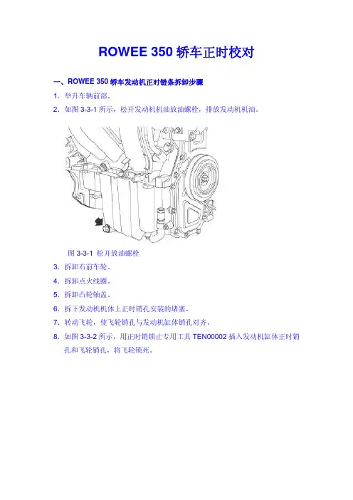
ROWEE 350轿车正时校对一、ROWEE 350轿车发动机正时链条拆卸步骤1.举升车辆前部。
2.如图3-3-1所示,松开发动机机油放油螺栓,排放发动机机油。
图3-3-1 松开放油螺栓3.拆卸右前车轮。
4.拆卸点火线圈。
5.拆卸凸轮轴盖。
6.拆下发动机机体上正时销孔安装的堵塞。
7.转动飞轮,使飞轮销孔与发动机缸体销孔对齐。
8.如图3-3-2所示,用正时销锁止专用工具TEN00002插入发动机缸体正时销孔和飞轮销孔,将飞轮锁死。
图3-3-2 插入锁止工具9.用凸轮轴锁止专用工具TEN00004将凸轮轴相位锁止。
10.拆卸发动机附件传动皮带。
11.拆下将曲轴皮带轮固定到曲轴上的紧固螺栓,将该螺栓废弃。
12.取下曲轴皮带轮。
13.用皮带轮拆装专用工具TEN00009拆卸水泵皮带轮,如图3-3-3所示。
图3-3-3 拆卸水泵皮带轮14.拆卸正时链条上盖板:(1)如图3-3-4所示,松开正时链条上盖板的8个螺栓(2个M6×35,6个M6×20)。
图3-3-4 松开正时链条上盖板的固定螺栓(2)拆下正时链条上盖板。
15.拆卸正时链条下盖板:(1)如图3-3-5所示,松开正时链条下盖板的固定螺栓。
图3-3-5松开正时链条下盖板的固定螺栓(2)拆下正时链条下盖板。
16.拆下正时链条张紧器并废弃密封垫圈。
如图3-3-6所示。
图3-3-6拆下正时链条张紧器并废弃密封垫圈17.如图3-3-7所示,拆卸正时链条上导轨。
图3-3-7拆卸正时链条上导轨18.如图3-3-8所示,用机油泵链轮固定专用工具TEN00006拆卸机油泵链轮螺栓。
图3-3-8 用专用工具拆卸机油泵链轮螺栓19.向右张开机油泵链条张紧器,将机油泵链轮、机油泵链条和驱动机油泵的曲轴链轮同时取下。
20.如图3-3-9所示,拆卸机油泵链条张紧器。
图3-3-9 机油泵链条张紧器21.拆下进气相位调节器螺栓并将其废弃。
22.如图3-3-10所示,用凸轮轴链轮固定专用工具TEN00005拆卸排气凸轮轴链轮螺栓,并将螺栓废弃。

荣威350六方位介绍荣威350六方位介绍一、车前方现在为大家介绍一款同级别车当中最具性价比,关注度最高,最符合网络时代的中级轿车,荣威350。
350是上海汽车集合全球资源、由上汽英国技术中心主导设计的。
在详细介绍车之前,先来讲讲荣威品牌的故事,荣威源自英国的罗孚,它有着一百多年的历史,文化底蕴非常丰富,荣威取意创新殊荣,威仪四海。
LOGO 的设计,充分体现了经典、尊贵、内蕴的气质。
由中国传统的红黑金三色构成:红色是中华民族的传统颜色,象征着热烈与喜庆,金色象征着富贵,而黑色则象征着威仪和庄重。
核心图案是两只屹立的雄狮护卫着华表,象征着我们中华民族的威严,不是所有的品牌可以采用华表的设计,这就是身份的代表。
Fliying-V 品牌基因在荣威350上得到完整的延续。
独特的翼展饰条托起荣威标识,使荣威的前脸看上去朝气蓬勃,舒展向上。
猎鹰眼式的前大灯,采用双圆环结构式反射瓦的仿生学设计,让光束更集中,并带有大灯延迟关闭功能,温馨便利的设计融贵气与时尚于一身。
引擎盖盾形特征线延续翼展式的格栅设计,与荣威品牌特征相呼应,锋利的线条营造非凡的动势,蓄势待发。
飞狐式智能无骨雨刮,当调至间歇档时,雨刮速度随车速自动变化,有效降低高速行驶时的风燥和风阻,无骨雨刮具有受力均匀,作用面积大,使用寿命长的三大优点,通过调整雨刮的安装位置,达到了欧洲行人的保护要求,真正体现人性关爱。
高质环保超安全玻璃,陶瓷黑边涂层,绿色环保,可回收,PLA 粘接层,防止碎裂时玻璃飞溅,保障前排安全,全型面控制,实现零差异精细质监。
二、驾驶座Loetsch 全息数字仪表,银亮的镀铬装饰圈呈现出3D 立体效果,高雅白色背景照明,亮度可以四级调节,并带有多功能行车电脑,日常所需的行车信息如平均油耗,续航里程,速度,引擎水温,燃油轻松掌握,大大提高您行车的安全性。
Floating 悬浮中控台,采用独特的悬浮设计理念,更贴切荣威品牌基因飞翔的感觉,同时中控操作面板也采用Fling-V 设计,与外饰呼应,并结合横向贯穿水转印饰条,强调宽敞的横向空间。
NAV350操作手册(中文)操作指南N A V350Laser Positioning SensorNavigating the route to improved productivitySoftware version Operating Instructions软件版本NAV350的软件是加密的. 出厂初始密码为:NAV350适用于工业场合.当用于居民区是会产生无线干扰。
C o p y r i ghtCopyright ? 2011SICK AG WaldkirchAuto Ident, Reute P l a n tNimburger Stra?e 1179276 ReuteG e r m anyT r ad e m ar k sWindows 2000?, Windows X P?, Windows Vist a?and Windows 7?are registered trademarks of Microsoft Corporation in the USA and other countries.Adobe? Reader?is a trademark of Adobe Systems Incorporated.Version of the operating instructionsThe latest version of these operating instructions can be obtained as PDF at .Operating InstructionsTable of contents1 About this document (8)1.1 Function of this document (8)1.2 Target group (8)1.3 Depth of information (8)1.4 Symbology used (9)2 For your safety (10)2.1 Authorised personnel (10)2.2 Correct use (11)2.3 General safety notes and protective measures (12)2.4 Quick stop and Quick restart (13)2.5 Environmental protection (14)3 Product description (15)3.1 Delivery (15)3.2 Construction of the NAV350 (16)3.3 Special features of the NAV350 (18)3.4 Applications (18)3.5 Operating principle of the NAV350 (19)3.6 Landmark detection (23)3.7 Navigation (24)3.8 Output of measured values (31)3.9 Integration of the NAV350 in an AGV’s control system (32)3.10 Planning (36)4 Mounting (44)4.1 Overview of the mounting steps (44)4.2 Preparations for mounting (44)4.3 Mounting and adjustment of the device (44)4.4 Dismantling the NAV350 (45)5 Electrical installation (46)5.1 Overview of the installation steps (46)5.2 Connections of the NAV350 (46)5.3 Preparing the electrical installation (47)5.4 Undertaking electrical installation on the NAV350 (48)6 Commissioning and configuration (51)6.1 Overview of the commissioning steps (51)6.2 SOPAS ET configuration software (51)6.3 Establish communication with the NAV350 (52)6.4 Initial commissioning (54)6.5 Connection and test measurement (56)6.6 Loading reflector data (56)7 Maintenance (57)7.1 Maintenance during operation (57)7.2 Exchanging an NAV350 (58)8 T r o ub l e s ho o t i n g (59)8.1 In the event of faults or errors (59)8.2 Monitoring error and malfunction indications (59)8.3 Troubleshooting and rectification (60)8.4 Detailed error analysis (60)8.5 SICK support (61)9 Technical specifications (62)9.1 Data sheet NAV350 (62)9.2 Dimensional drawings (64)10 Annex (66)10.1 Overview of the annexes (66)10.2 Ordering information (66)10.3 Glossary (67)10.4 EC declaration of conformity (68)Operating Instructions Figures and tablesAbbreviationsAGV Automated guided vehicleCoLa Communication Language = proprietary SOPAS ET communication language(ASCII = C o L a F A or binary = Co L a F B)EEPROM Electrically Erasable Programmable R ea d-o n ly M e m o r yLED Light Emitting DiodeRAM Random Access Memory = volatile memory with direct accessROM R ea d-o n l y Memory (permanent)SOPAS ET SICK OPEN PORTAL for APPLICATION and SYSTEMS ENGINEERING TOOL = configurationsoftware for the configuration of the N A V350Figures and tables Operating InstructionsT ab l esTab. 1: Target groups of this document (8)Tab. 2: Authorised personnel (10)Tab. 3: Delivery (15)Tab. 4: Meaning of the LED status indicators (17)Tab. 5: Special features of the NAV350 (18)Tab. 6: Typical remissions and scanning ranges (22)Tab. 7: Frame for the telegrams with ASCII coding (33)Tab. 8: Beam diameter at different distances from the NAV350 (37)Tab. 9: Pin assignment of the ―Power‖ connection on the NAV350 (47)Tab. 10: Pin assignment of the ―E t h e r n e t‖connection on the NAV350 (47)Tab. 11: Pin assignment of the ―R S F232‖c onnection on the NAV350 (47)Tab. 12: Maximum cable lengths for the supply voltage (48) Tab. 13: Maximum length of cable for the data interface (48) Tab. 14: SOPAS ET default setting (52)Tab. 15: Password NAV350 (55)Tab. 16: Troubleshooting and rectification (60)Tab. 17: Data sheet NAV350 (62)Tab. 18: Consumables (66)Operating Instructions Figures and tablesFiguresFig. 1: Laser output aperture on the NAV350 (13)Fig. 2: Views of device (16)Fig. 3: Measuring principle of the NAV350 (19)Fig. 4: Principle of operation of the NAV350 (20)Fig. 5: Diffuse reflection from objects (21)Fig. 6: Directional reflection from reflectors (21)Fig. 7: Possible sources of errors during the measurement (21) Fig. 8: Beam diameter and distance between measured points at 0 to 100 m (22)Fig. 9: Landmark detection (23)Fig. 10: Determination of the position by the N A V350by means of the detection of reflector placements (24)Fig. 11: Identification of reflectors in the operational status ―continuous positio ning‖25Fig. 12: Radius of the detection window as a function of the distance (26)Fig. 13: Filter N-CLOSEST (27)Fig. 14: Restricted action radius (28)Fig. 15: Example for the definition of muted sectors (29)Fig. 16: Overlapping of two reflectors (30)Fig. 17: Minimum distance from reflectors to other reflecting objects (30)Fig. 18: Output of measured values for truck loading (31)Fig. 19: Requesting an absolute position or landmark positions (32)Fig. 20: Integration of the NAV350 in a navigation system (33) Fig. 21: Pulse for synchronisation (34)Fig. 22: Increase in the size of the beam and safety supplement (37)Fig. 23: Absolute and local coordinate system with angular position of the NAV350 (38)Fig. 24: Reflector height as a function of the distance from 0 to 70 m (39)Fig. 25: Correct, asymmetrical placement andincorrect, symmetrical placement of reflectors (41)Fig. 26: Common usage of the reflectors from two neighbouring layers (43)Fig. 27: Fixing bracket for the NAV350 (45)Fig. 28: Connections of the NAV350 (46)Fig. 29: Connection of the voltage supply (49)Fig. 30: Ethernet connection (49)Fig. 31: Wiring the RS F232 interface (49)Fig. 32: RS F232connection (50)Fig. 33: Principle of data storage (54)Fig. 34: Example text file with reflector data (56)Fig. 35: Window in the scanner head on the NAV350 (57)Fig. 36: Dimensions NAV350 (64)Fig. 37: Dimensions fixing bracket for NAV350 (65)Fig. 38: Illustration containing the EU declaration of conformity (68)Figures and tables Operating Instructions1 About this documentPlease read this chapter carefully before working with this documentation and the laserpositioning sensor N A V350.1.1 Function of this documentThese operating instructions are designed to address the technical personnel in regards tosafe mounting, electrical installation, configuration, commissioning and maintenance of thefollowing laser positioning sensor.1.2 Target groupThe intended target group for this document is people in the following positions:Tab. 1: Target groups of this document1.3 Depth of informationThese operating instructions contain the following information on the N A V350:product descriptionelectrical installationcommissioning and configurationmaintenancetroubleshooting and rectificationordering informationconformity and approvalPlanning and using a laser positioning sensor such as the NAV350 also require specifictechnical skills which are not detailed in this documentation.In addition, an online help is available in the SOPAS ET configuration software supplied; thishelp provides information on the usage of the software user interface, as well as on theconfiguration of the N A V350.Further information on the NAV350 is available from SICK AG, Division Auto Ident, and inthe Internet at .Important In the following the laser positioning sensor is referred to as NAV350 for short.Operating InstructionsChapter 11.4Symbology usedRecommendation Recommendations are designed to give you assistance in the d ec i s ion -m a k ing process with respect to a certain function or a technical measure.Important Sections marked ―Important ‖ provide information about special features of the device. Explanation Explanations provide background knowledge on technical relationships. M ENU COMMAND This typeface indicates a term in the SOPAS ET user interface.Terminal output This typeface indicates messages that the NAV350 outputs via its i n t e r f ace s.Take action … Here you must do something. This symbol indicates an instruction to perform an action thatcontains only one action or actions in warnings where a specific sequence does not need to be followed. Instructions to perform actions that contain several steps in a specific sequence are numbered.This symbol refers to additionally available documentation.Software notes show where you can make the appropriate settings and adjustments in the SOPAS ET configuration software.Note!A note provides indicates potential hazards that could involve damage or degradation of the functionality of the NAV350 or other devices.Warning!A warning indicates an actual or potential hazard. They are designed to help you to prevent accidents.The safety symbol beside the warning indicates the nature of the risk of accident, e.g. due to electricity. The warning category (DANGER, WARNING, CAUTION) indicates the severity of the hazard.Read carefully and follow the warning notices!Chapter 2For your safety Operating Instructions2 For your safetyThis chapter deals with your own safety and the safety of the equipment operators.Please read this chapter carefully before working with the NA V350.2.1 Authorised personnelThe NAV350 must only be installed, commissioned and serviced by adequately qualifiedpersonnel.Repairs to the NAV350 are only allowed to be undertaken by trained and authorised servicepersonnel from SICK AG.The following qualifications are necessary for the various tasks:Tab. 2: Authorised personnelOperating Instructions For your safety Chapter 22.2 Correct useThe NAV350 laser positioning sensor is intended for use in industrial environments. Whenused in residential areas, it can cause radio interferences.The NAV350 is used to determine the position of automated guide vehicles (AGV) at a pointon the programmed route. Fitted to an AGV, the NAV350 continuously measures thepositions of reflectors detected as well as the surrounding contour. Depending on theoperating mode selected, the NAV350 outputs to the AGV’s vehicle computer the positionof the reflectors, or its own position, as well as the distance, the angle and the remission ofthe surrounding contour seen. The vehicle computer can use this information to correct thecourse of the AGV as necessary to keep it to the route.The NAV350 is a sensor for use indoors.Important In case of any other usage as well as in case of modifications to the NAV350, e.g. due toopening the housing during mounting and electrical installation, or to the SICK software, anyclaims against SICK AG under the warranty will be rendered void.The NAV350 is only allowed to be operated in the ambient temperature range allowed (seesection 9.1 “Data sheet NAV350”on page 62).Chapter 2For your safety Operating Instructions2.3 General safety notes and protective measuresSafety notesPlease observe the following items in order to ensure the correct and safe use of theN A V350.The notices in these operating instructions (e.g. on use, mounting, installation orintegration into the existing machine controller) must be observed.When operating the NAV350, the national, local and statutory rules and regulationsmust be observed.N a t iona l/in t e r na t ion a l rules and regulations apply to the installation, commissioning,use and periodic technical inspections of the NAV350, in particular– the work safety r e g u l at i o n s/s afe t y rules– other relevant health and safety regulations.Manufacturers and operators of the m ac h i n e/s y s t e m on which the NAV350 is installedare responsible for obtaining and observing all applicable safety regulations and rules.The tests must be carried out by specialist personnel or specially qualified andauthorised personnel and must be recorded and documented to ensure that the testscan be reconstructed and retraced at any time.The operating instructions must be made available to the operator of the system wherethe NAV350 is used. The operator of the system is to be instructed in the use of thedevice by specialist personnel and must be instructed to read the operatinginstructions.The NAV350 is not a device for the protection of people in the context of the relatedsafety standards for m ac h i n e r y.2.3.1 Electrical installation workOnly authorised personnel are allowed to perform the electrical installation work.Only make and disconnect electrical connections when the device is e l ec t r i ca ll yisolated.Select and implement wire c r oss-sec t io ns and their correct fuse protection as per theapplicable standards.Do not open the housing.Observe the current safety regulations when working on electrical systems.Operating Instructions For your safety Chapter 22.3.2 Laser radiation of the N A V350Laser radiation!The NAV350 complies with laser class 1 (eye safe) in accordance with EN 60825-1.Complies with 21 CFR 1040.10 with the exception of the deviations as per Laser Notice No.50, July 26, 2001. The laser beam cannot be seen with the human e y e.Incorrect usage can result in hazardous exposure to laser radiation.Do not open the housing (opening the housing will not switch off the laser).Pay attention to the laser safety regulations as per EN 60825F1(latest version).Important No maintenance is necessary to ensure compliance with laser class 1.Laser output apertureThe laser output aperture is the view window on the scanner head of the N A V350.Fig. 1: Laser output aperture on the N A V350Laser powerThe laser operates at the wavelength λ= 905 nm (invisible infrared light). The radiationemitted in correct use is not harmful to the eyes and human skin.2.4 Quick stop and Quick restart2.4.1 Switch the NAV350 o ffSwitch off the voltage supply (power supply) for the N A V350.The NAV350 retains parameters stored in the internal, n o n-v o l a t i l e memory. Measuredvalues in the memory are lost.2.4.2 Switch on the N A V350Switch on voltage supply (power supply) for the N A V350.Th e NAV350 restarts operation with the last saved parameters.Chapter 2For your safety Operating Instructions2.5 Environmental protectionThe NAV350 has been designed to minimise environmental impact. It uses only a minimumof power.While working, always act in an environmentally responsible manner. For this reason pleasenote the following information on disposal.2.5.1 Power consumptionThe NAV350 consumes a maximum of 36 W in operation.2.5.2 Disposal after final d e-co mm is s io n in gAlways dispose of unserviceable or irreparable devices in compliance with l oca l/national rules and regulations on waste disposal.Dispose of all electronic assemblies as hazardous waste. The electronic assemblies arestraightforward to dismantle.Important SICK AG does not accept unusable or irreparable devices that are returned.Operating Instructions Product description Chapter 33 产品描述本章提供了NAV350的特点和属性,描述了本设备结构和工作原理,尤其是不同的操作模式。
荣威350整车电路图手册(可编辑)荣威350整车电路图手册目录序言 .................................................................. .. (7)关于这份文件 . 7概要 7参考 7蓄电池电压 . . 7电气防护 . 8概要 8设备 8极性 8高压电路 . . . 8连接器和线束 . 8蓄电池断开 . . 8蓄电池充电 . . 8规则 8缩略语 . . 9概要 9电线颜色代号 . . . 12概要 . . . . 12以下表格是线束颜色代号代表的颜色 12 线束简称 13概要 . . . . 13线束配置代码表 . . 14概要 . . . . 14电源线路功能 . . . 15电源线路功能编号的含义 15电源线路图示 15连接器列表说明 . . 16概要 . . . . 16例表: . . . . 16例图: . . . . 16故障诊断 17概要 . . . . 17如何使用电路图 . . 18导线跨页 . . 18屏蔽线 . . . 18双绞线 . . . 19双绞线在电路图如上图所示。
. . . . 19 部件 . . . . 19导线属性 . . 191V0.1如何使用电路图 20连接器 . . . .20部件端连接器 .20对接连接器 . .20定位图 .................................................................. .. (21)发动机线束 -正面 . . . . 21发动机线束 -背面 . . . . 22自动变速箱线束 23暖风机线束 (自动恒温空调 . . . . 24暖风机线束 (电子控制空调 .25发动机舱线束 . . .26车身线束,前地板 .27车身线束,发动机舱 28车身线束 - 左侧 . .29车身线束 - 右侧 . .30仪表板线束 . . . .31驾驶侧门线束 . . .33副驾驶侧门线束 . .34左后门线束 . . . .35右后门线束 . . . .36尾门线束 37顶蓬线束 38接地点俯瞰图 . . .39保险丝说明 .................................................................. . (40)概要 . .40发动机舱保险丝盒 .41乘客舱保险丝盒 . .44电源分配电路图 ..................................................................46发动机舱电源分配 .46发动机舱电源分配 .47发动机舱电源分配 .48发动机舱电源分配 .49发动机舱电源分配 .50发动机舱电源分配 .51发动机舱电源分配 .52乘客舱电源分配 . .53乘客舱电源分配 . .54乘客舱电源分配 . .55乘客舱电源分配 . .562V0.1目录维修电路图 .................................................................. . (58)1. 起动&充电 58A .连接器信息 59B . 连接器端视图 . . . 602. 发动机管理系统-1.5L(1) 61A .连接器信息 62B . 连接器端视图 . . . 633. 发动机管理系统-1.5L(2) 64A .连接器信息 65B . 连接器端视图 . . . 664. 发动机管理系统-1.5L(3) 67A .连接器信息 68B . 连接器端视图 . . . 695. 发动机管理系统-1.5L(4) 70A .连接器信息 71B . 连接器端视图 . . . 726. 发动机管理系统-1.5L(5) 73A .连接器信息 74B . 连接器端视图 . . . 757. 发动机管理系统-1.5L(6) 76A .连接器信息 77B . 连接器端视图 . . . 788. 冷却风扇 79A .连接器信息 80B . 连接器端视图 . . . 819. 燃油泵&惯性开关 82A .连接器信息 83B . 连接器端视图 . . . 8410. 自动变速箱,TCU 1 85A .连接器信息 86B . 连接器端视图 . . . 8711. 自动变速箱, TCU 2 88A .连接器信息 89B . 连接器端视图 . . . 9012. 自动变速箱, TCU 3 91A .连接器信息 92B . 连接器端视图 . . . 9313. 自动控制空调,ATC 1 94A .连接器信息 95B . 连接器端视图 . . . 96 14,自动控制空调-ATC 2 97A .连接器信息 983V0.1B . 连接器端视图 . . . .99 15,自动控制空调-ATC 3 100 A . 连接器信息 101B . 连接器端视图 . . . 102 16,电子控制空调,ETC 1 103A . 连接器信息 104B . 连接器端视图 . . . 105 17,电子控制空调,ETC 2 106A . 连接器信息 107B . 连接器端视图 . . . 108 18,ABS,DSC和牵引力控制 109A . 连接器信息 110B . 连接器端视图 . . . 111 19,组合仪表 1 112A . 连接器信息 113B . 连接器端视图 . . . 114 20,组合仪表 2 115A . 连接器信息 116B . 连接器端视图 . . . 118 21,组合仪表 3 119A . 连接器信息 120B . 连接器端视图 . . . 12122. 驾驶员座椅 122A . 连接器信息 123B . 连接器端视图 . . . 124 23,后视镜 125A . 连接器信息 126B . 连接器端视图 . . . 127 24,天窗 128A . 连接器信息 129B . 连接器端视图 . . . 130 25,雨刮器和洗涤器 131A . 连接器信息 132B . 连接器端视图 . . . 133 26,内部灯光 134A . 连接器信息 135B . 连接器端视图 . . . 136 27,转向灯&危险警告灯 137A . 连接器信息 138B . 连接器端视图 . . . 140 28,雾灯 141A . 连接器信息 1424V0.1目录B . 连接器端视图 . . . 143 29,制动灯&尾灯 144A .连接器信息 145B . 连接器端视图 . . . 147 30,倒车灯 148A .连接器信息 149B . 连接器端视图 . . . 15031,前照灯-近光 151A .连接器信息 152B . 连接器端视图 . . . 15432,前照灯,远光 155A .连接器信息 156B . 连接器端视图 . . . 15733,前位置灯 158A .连接器信息 159B . 连接器端视图 . . . 16034,车窗升降 1 161驾驶员车窗电机,驾驶员车窗开关 . 161A .连接器信息 162B . 连接器端视图 . . . 16335,车窗升降 2 164A .连接器信息 165B . 连接器端视图 . . . 16736,车窗升降 3 168A .连接器信息 169B . 连接器端视图 . . . 17037,喇叭 171A .连接器信息 172B . 连接器端视图 . . . 17338,车辆安全系统 1 174A .连接器信息 175B . 连接器端视图 . . . 176 39,车辆安全系统 2 177A .连接器信息 178B . 连接器端视图 . . . 180 40,防盗&锁止 1 181A .连接器信息 182B . 连接器端视图 . . . 183 41,防盗&锁止 2 184A .连接器信息 185B . 连接器端视图 . . . 186 42,安全气囊,回路 1875V0.1A . 连接器信息 188B . 连接器端视图 . . . 189 43,安全气囊,回路 1 190A . 连接器信息 191B . 连接器端视图 . . . 192 44,安全气囊,回路 2 193A . 连接器信息 194B . 连接器端视图 . . . 195 45,停车距离控制 PDC 196A . 连接器信息 197B . 连接器端视图 . . . 19846,音响系统,导航 1 199A . 连接器信息 200B . 连接器端视图 . . . 20147,音响系统,导航 2 202A . 连接器信息 203B . 连接器端视图 . . . 20548,音响系统,CD 1 206A . 连接器信息 207B . 连接器端视图 . . . 20849, 音响系统, CD 2 . . 209A . 连接器信息 210B . 连接器端视图 . . . 21250,总线系统和诊断接口 213A . 连接器信息 214B . 连接器端视图 . . . 2166V0.1序言序言关于这份文件概要这份文件旨在帮助您诊断电气故障。
CN 1-8NOMAD POWERVAC 350产品操作界面1LED运行灯2ON / OFF 开关键3充电指示灯4USB-C输入端口5USB输出端口6启动电缆接口7不锈钢滤网8可水洗滤网9智能夹10操作线LED灯11“超强启动”键 12USB-C线13毛刷14集尘槽962INSTRUCTIONS DE SÉCURITÉ本说明书包含有关设备操作的信息以及安全注意事项等内容。
请仔细阅读并妥善保管。
操作前,请仔细阅读说明书。
所有未在说明书内标明的修改与维护,本公司概不负责。
不按照本使用说明使用而造成的任何人身伤害或财产损失,制造商一律不负责。
出现问题或有疑问,请联系专业人员对设备进行正确干预。
该设备必须仅用于设备和说明书指示范围内的充电和/或启动和/或吸尘。
严格遵守安全准则。
如使用不当或危险使用,制造商概不负责。
8岁以下儿童不可进行操作。
有自主活动能力、感知力和精神能力的但缺乏操作经验的人员在接受了相应的操作指导,掌握了安全操作条例后,在严格监管下可以操作机器。
机器不可给儿童玩耍。
机器的清理维护不可在无人监管的情况下由儿童进行。
不可用于给非可充电电池进行充电。
仅使用和产品一起附带的充电器为电池充电.若充电线已损坏或连接错误,请勿使用本设备,以防电池短路(NOMAD电源充电器)。
不能用于给已冻结的或损坏的电池充电。
不要盖住机器不要将机器放置于靠近热源处或温度持续高于50度的地方。
充电夹短路或设备启动电压与车辆电瓶电压不符的情况下可能会发生爆炸或酸溅。
自动模式和应用限制在后面的使用模式内容中有详细解释。
易燃易爆!正在充电的电池可能释放易爆气体• 充电过程中,电池应放于通风良好处。
• 机器使用范围内避免火花,电弧。
禁止抽烟。
注意防范酸化物质喷溅危险!• 操作时请佩戴专业的防护眼镜和手套。
• 如果有物质直接接触到了眼睛或皮肤,立即用水清洗并咨询医生。
电源连接/断开• 连接机器前请先断开电源连接,或者断开电池上的连接。
荣威350用户手册一、车辆概述荣威350是一款由上汽集团生产的紧凑型轿车,以其卓越的性能、舒适性以及安全性而广受好评。
作为一款面向家庭的轿车,荣威350拥有丰富的配置和功能,以满足您在日常生活和工作中的各种需求。
二、驾驶指南1、车辆启动:请确保档位在停车档(P档),并踩下刹车踏板。
按下一键启动按钮,车辆将启动。
2、驾驶操作:在驾驶过程中,请注意遵守交通规则和安全驾驶。
请根据路况调整车速,并注意保持与前方车辆的距离。
3、停车:当您需要停车时,请先减速,然后踩下刹车踏板。
车辆停止后,将档位调整为停车档(P档),并拉起手刹。
三、车辆功能介绍1、空调系统:荣威350配备了空调系统,可以调节车内温度。
请确保在驾驶前开启空调,以提供舒适的驾驶环境。
2、音响系统:荣威350配备了音响系统,支持CD、USB和蓝牙等多种音频输入方式。
您可以通过中控台上的音响系统来播放您的音乐。
3、行车电脑:荣威350配备了一键式行车电脑,可以显示车辆的各种信息,如油耗、行驶里程等。
4、巡航系统:荣威350配备了巡航系统,可以在高速行驶时减轻驾驶压力。
请根据需要开启和调整巡航系统。
5、倒车雷达:荣威350配备了倒车雷达,可以帮助您在倒车时感知周围环境,提高倒车安全性。
四、安全提示1、安全带:请在驾驶过程中始终佩戴安全带,包括前排和后排乘客。
2、行车安全:请在驾驶过程中保持注意力,避免使用手机或其他分散注意力的行为。
3、车辆保养:定期对车辆进行保养,以确保车辆的性能和安全性。
本用户手册旨在为使用Vacon变频器的用户提供详细的使用指南和操作建议。
Vacon变频器是一种广泛使用的电力转换设备,可实现交流电源频率的稳定输出,适用于各种工业和商业应用。
在阅读本手册之前,我们建议用户仔细阅读本手册,并按照指南进行操作,以确保安全和设备正常运行。
Vacon变频器是一种高性能的交流变频器,具有高精度、高稳定性、高可靠性等优点。
它采用先进的电力电子技术和数字控制技术,可以根据实际需求调整电源频率,实现电机的无级调速。