FreeCam用户手册
- 格式:pdf
- 大小:1.77 MB
- 文档页数:21

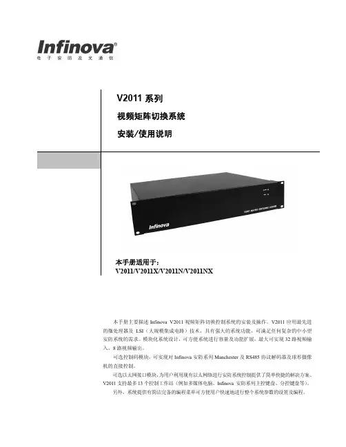
FreeWAF安装手册目录前言 (3)文档范围 (3)预期读者 (3)获得帮助 (3)格式&单位约定 (3)1.产品介绍 (4)1.1.产品概述 (4)1.2.产品特性 (5)1.2.1.硬件规格 (5)1.2.2.软件规格 (5)1.3.产品许可证 (7)2.产品安装准备 (9)2.1.硬件准备 (9)2.2.软件准备 (10)3.产品安装 (13)3.1.第一步:开机 (13)3.2.第二步:安装主界面 (13)3.3.第三步:选择语言 (13)3.4.第四步:分区 (14)3.5.第五步:开始安装 (16)3.6.第六步:结束安装 (22)3.7.第七步:首次登录 (23)4.基本配置 (24)4.1.CLI基础配置 (24)4.1.1.管理口IP地址配置 (24)4.1.2.CLI配置简单介绍 (24)4.2.Web网管配置 (26)5.FreeWAF网络部署 (28)5.1.离线模式 (28)5.1.1.网络拓扑 (28)5.1.2.配置方式 (29)5.2.在线模式 (35)5.2.1.网桥透明代理 (35)5.2.2.路由透明代理 (39)5.2.3.反向代理 (41)6.初始化信息 (47)6.1.管理口IP地址初始值 (47)6.2.系统账号 (47)前言文档范围本文将覆盖Free Web应用防火墙(Free Web Application Firewall,以下简称FreeWAF)的安装,详细介绍安装过程。
本文档可以作为FreeWAF系统的管理员进行运维管理的指导性手册。
其他可用文档:●《FreeWAF命令参考》●《FreeWAF使用指南》●《FreeWAF开发指南》预期读者期望了解本产品主要技术特性和使用方法的用户。
本文假设您对下面的知识有一定的了解:●Web服务器和Web应用,比如:Nginx、Apache、IIS、Tomcat等。
●Linux操作系统。
●网络基础知识,包括:桥、路由、TCP/IP、HTTP和HTTPS等。
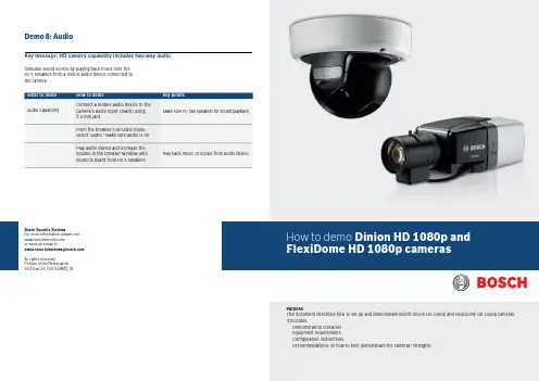
Perfect picture qualityWhen monitoring colorful scenes with a high amount of activity, seeing all the details is critical for safety and security. Part of the Bosch high definition (HD) portfolio, the Dinion and FlexiDome HD 1080p Day/ Night IP cameras deliver uncompromising vision even in the busiest scenes. Combining very high resolution images with excellent low light operation and color reproduction, these high quality systems deliverbest-in-class performance.A specially selected image sensor delivers superior detection and analysis even in low light conditions. Images are clearer and have less motion blur, making it easier to identify items. They also require less bandwidth to transmit due to reduced image noise. Even in low light conditions, first-class color reproduction delivers a clear differentiation between color tonesSmart Backlight Compensation (BLC) automatically compensates the image by optimizing light levels for objects of interest without compromising the Dynamic Range. Additionally, the sharpness slider applies detail enhancement to the whole scene, while sharpness automatically enhances every pixel. Reduced storage, automatic scene analysisand alarm functionalityH.264 video compression ensures the best image quality, while minimizing storage and bandwidth requirements. Bosch IVA can analyze a scene and alert your security personnel to any suspicious activity. Alarm functionality enables you to trigger alarm systems or start the camera recording when an event is detected. And, audio lets you hear as well as see what is going on. The camera sends an alarm for sudden or loud noises, alerting your security team to a potential problem.Local Storage & Automatic Network Replenishment (ANR)Dinion HD & FlexiDome HD cameras support local storage with a microSD card. The cameras support SXHC microSD cards and can use microSD cards with up to 2 TB. Local storage can be used for alarm recording or for ANR.Easy installationBosch IP cameras are easy to set up. Just mount, plugin, and they operate immediately on the IP network.Software detects and configures the camerasautomatically while allowing quick changes to bemade to the settings. It’s easy to get the sharpestimage the first-time thanks to our best-in-classmotorized auto-back-focus.To make installation and configuration easy, theDinion HD and FlexiDome HD are shipped with BoschVideo Client (BVC) and configuration client. Thecameras comply with PoE (Power over Ethernet) andare ONVIF conformant.Dinion HD allows for customization with specificlenses and housings while the FlexiDome HD comeswith lens, housed in a convenient, rugged dome.EquipmentHere is the equipment you need for the demos.FlexiDome HD 1080p system④Camera④PSU (Optional)④PoE compliant Ethernet Switch④BVC & Configuration Manager version BVC 1.1.500 orlater④PC with Internet Explorer 6 or later1④Monitor2Fixed body Dinion HD 1080p system④Camera④PSU (Optional)④PoE compliant Ethernet Switch④BVC & Configuration Manager④HD Lens④Desk tripod④IR Illuminator④PC with Internet Explorer 6 or later1④Monitor2Demonstration materials (from Dinion 2X demo kit)④Colorful toy (little demo duck)④VRM with iSCSI (only for ANR demo)Audio demonstration material④Mobile audio device (or Mp3 Player)④Connecting cable with 3.5 mm jackNotes1 See user manual for current system requirements.2We recommend you use a Bosch HD Monitor 16:9format.Demo 1: Installation and configurationKey message: ease of installation / set-upEase of installation is shown more clearly by demonstratingthe fixed-body IP camera, so we recommend you use theDinion HD unless your customer expressly asks for theFlexiDomeHD IP.In both cases the features demonstrated are the same.The steps below guide you through the installation demo forboth Dinion IP and FlexiDome IP cameras. The configurationmanager and all other software are on the disk and shouldbe installed prior to giving the demo.Key message: Automatic image compensation in backlit scenesDemo 4 (optional): Smart BLCDemo 3: IP functionalityKey message: see more clearly in harsh lighting conditions and reveal more detailDemonstrate in BVC that the customer can see HD & SD camera simultaneously, so we have one solution for the entire family.Demo 2: HD image processingKey message: delivering high quality, real-time H.264 video over IPThe superior performance of Bosch cameras due to advanced image processing is shown in the Competition benchmarking slides of the introduction presentation.Follow the instructions below to demonstrate IPfunctionality of both Dinion HD and FlexiDome HD e the demo duck toy to demonstrate the benefits of Smart BLC. You can also find video snapshots illustrating this feature on the introduction presentation.Key message: Intelligence at the edge – processing done in the camera, not in a central video management or PC stationDemo 6: Intelligent Video Analysis (IVA)Key message: Up to four easily configurable privacy zonesDemo 5 (optional): Privacy zonesDemo 7: Local StorageKey message: Dinion HD & FlexiDome HD can store video locally on a microSD cardThis demo is easy to show the customer with the camera on a table. Follow the steps below to guide you through the Privacy zones demo.Demonstrate local recording in microSD card and optionally demonstrate Dual recording and ANR (if VRM is also available). For ANR ensure that duration of gap is more than 1 minute.。


Electronic Chart Display and Information System (ECDIS)OPERATOR'S MANUALwww.furuno.co.jpMODEL FEA-2107 FEA-2107-BB FEA-2107-D FEA-2807FEA-2807-DInstructions for use with Autopilots: FAP-2000PT -500A(CAT B, CAT C) PR-6000The paper used in this manualis elemental chlorine free.9-52 Ashihara-cho,Nishinomiya, 662-8580, JAPANForewordThe purpose of this manual is to provide the instructions for how to use the Autopilots FAP-2000,PT-500A(CAT B and CAT C)1 and PR-60002 with the FURUNO FEA-2107-D, FEA-2107-BB-D, FEA-2807-D Electronic Chart Display and Information System (ECDIS). For ECDIS operating information, see its Operator's Manual.1 PT-500A(CAT B and CAT C) are products of YOKOGAWA ELECTRIC CORPORATION.2 PR-6000 is a product of TOKYO KEIKI INCImportant Notices• The operator of this equipment must read and follow the descriptions in this manual. Wrong operation can cancel the warranty or cause injury.• Do not copy any part of this manual without written permission from FURUNO.• If this manual is lost or worn, contact your dealer about replacement.• The contents of this manual and equipment specifications can change without notice.• The example screens (or illustrations) shown in this manual can be different from the screens you see on your display. The screens you see depend on your system configuration and equipment settings.• Save this manual for future reference.• Any modification of the equipment (including software) by persons not authorized by FURUNO will cancel the warranty.• All brand and product names are trademarks, registered trademarks or service marks of their respective holders.iSafety Instructionsiiabout replacement.ype: 86-003-1011-0Safety InstructionsTable of ContentsSYSTEM CONFIGURATION (vii)1.FURUNO Autopilot FAP-2000..............................................................................................1-11.1Introduction.............................................................................................................................1-11.2Control Panel...........................................................................................................................1-11.3Steering Modes........................................................................................................................1-31.3.1Hand steering modes..................................................................................................1-31.3.2Autopilot steering modes............................................................................................1-31.3.3Route steering modes..................................................................................................1-51.4Additional Information About Steering Modes....................................................................1-161.5Important Information About Steering Mode Changes......................................................1-181.6Autopilot Display in Sidebar.................................................................................................1-191.7Expected Steering Performance Under Various Conditions...............................................1-201.7.1Expected steering performance for going ahead.....................................................1-201.7.2Expected steering performance for turns................................................................1-231.8Expected Steering Performance Under Critical Failure.....................................................1-251.8.1Lost heading from autopilot (ECDIS may also have lost heading)........................1-251.8.2Lost heading from ECDIS (autopilot still has heading).........................................1-251.8.3Lost speed..................................................................................................................1-261.8.4Low speed..................................................................................................................1-261.8.5Lost SOG/COG reference..........................................................................................1-271.8.6Total lost position......................................................................................................1-281.8.7Lost differential position..........................................................................................1-291.8.8Lost differential position and position discrepancy................................................1-301.8.9Lost communication between ECDIS and autopilot...............................................1-301.8.10Lost communication between autopilot and ECDIS...............................................1-301.9Other Operations...................................................................................................................1-311.10Alerts......................................................................................................................................1-311.10.1Alerts generated by autopilot...................................................................................1-311.10.2Alerts generated by ECDIS......................................................................................1-321.10.3Error alerts generated by autopilot.........................................................................1-371.11How to Use the Curved EBL.................................................................................................1-381.11.1What is the curved EBL?..........................................................................................1-381.11.2Structure of the curved EBL.....................................................................................1-391.11.3How to design a new turn while the ship is turning...............................................1-391.12How to Use the Predictor......................................................................................................1-402.YOKOGAWA Autopilot PT-500A (category B).......................................................................2-12.1Introduction.............................................................................................................................2-12.2Steering Control Unit..............................................................................................................2-12.3Steering Modes........................................................................................................................2-22.3.1Hand steering mode (Mode selector: HAND)............................................................2-22.3.2Autopilot steering mode (Mode selector: AUTO).......................................................2-22.3.3Route steering mode (Mode selector: NAVI)..............................................................2-22.4Other Operations...................................................................................................................2-102.5Alerts Generated by ECDIS..................................................................................................2-102.5.1Operational alerts.....................................................................................................2-102.5.2Error alerts................................................................................................................2-132.6Autopilot Display in Sidebar.................................................................................................2-142.7Expected Steering Performance Under Various Conditions...............................................2-152.7.1Expected steering performance for going ahead.....................................................2-152.7.2Expected steering performance for turns................................................................2-162.8Expected Steering Performance Under Critical Failure.....................................................2-172.8.1Lost heading from autopilot (ECDIS may also have lost heading)........................2-172.8.2Lost heading from ECDIS (autopilot still has heading).........................................2-17iiiTable of Contentsiv2.8.3Lost speed..................................................................................................................2-182.8.4Low speed..................................................................................................................2-192.8.5Total lost position......................................................................................................2-202.8.6Lost differential position and position discrepancy................................................2-212.8.7Lost communication between ECDIS and autopilot...............................................2-222.8.8Lost communication between autopilot and ECDIS...............................................2-22 2.9How to Use the Curved EBL.................................................................................................2-23 2.10How to Use the Predictor......................................................................................................2-243.YOKOGAWA Autopilot PT-500A (category C).......................................................................3-13.1Introduction..............................................................................................................................3-13.2Steering Control Unit..............................................................................................................3-13.3Steering Modes.........................................................................................................................3-23.3.1Hand steering mode (Mode selector: HAND)............................................................3-23.3.2Autopilot steering mode (Mode selector: AUTO).......................................................3-23.3.3Route steering mode (Mode selector: NAVI)..............................................................3-23.4Other Operations...................................................................................................................3-113.5Alerts Generated by ECDIS..................................................................................................3-123.5.1Operational alerts.....................................................................................................3-123.5.2Error alerts................................................................................................................3-123.6Autopilot Display in Sidebar.................................................................................................3-133.7Expected Steering Performance Under Various Conditions...............................................3-143.7.1Expected steering performance for going ahead.....................................................3-143.7.2Expected steering performance for turns................................................................3-153.8Expected Steering Performance Under Critical Failure.....................................................3-163.8.1Lost heading from autopilot (ECDIS may also have lost heading)........................3-163.8.2Lost heading from ECDIS (autopilot still has heading).........................................3-163.8.3Lost speed..................................................................................................................3-173.8.4Low speed..................................................................................................................3-173.8.5Lost SOG/COG reference in GoAW mode................................................................3-183.8.6Total lost position......................................................................................................3-183.8.7Lost differential position in GoAW mode.................................................................3-193.8.8Lost differential position and position discrepancy................................................3-203.8.9Lost communication between ECDIS and autopilot...............................................3-213.8.10Lost communication between autopilot and ECDIS...............................................3-213.9How to Use the Curved EBL.................................................................................................3-214.TOKYO KEIKI Autopilot PR-6000.......................................................................................4-14.1Introduction..............................................................................................................................4-14.2Steering Control Unit..............................................................................................................4-14.3Steering Modes.........................................................................................................................4-24.3.1Hand steering mode (Mode selector: HAND)............................................................4-24.3.2Autopilot steering mode (Mode selector: AUTO).......................................................4-34.3.3Non-Follow-Up steering mode (Mode selector: NFU)...............................................4-34.3.4Remote hand steering mode (Mode selector: RC)......................................................4-44.3.5Steering override units...............................................................................................4-54.3.6Route steering mode, RC/Nav (Mode: RC).................................................................4-64.4HCS Unit Controls.................................................................................................................4-174.5Alerts Generated by ECDIS..................................................................................................4-184.5.1Operational alerts.....................................................................................................4-184.5.2Error alerts................................................................................................................4-184.6Autopilot Display in Sidebar.................................................................................................4-194.7Expected Steering Performance Under Various Conditions...............................................4-214.7.1Expected steering performance for going ahead.....................................................4-214.7.2Expected steering performance for turns................................................................4-224.8Expected Steering Performance Under Critical Failure.....................................................4-244.8.1Lost heading from autopilot (ECDIS may also have lost heading).......................4-244.8.2Lost heading from ECDIS (autopilot still has heading).........................................4-244.8.3Lost speed..................................................................................................................4-254.8.4Low speed..................................................................................................................4-25Table of Contentsv4.8.5 Lost SOG/COG reference in GoAW steering mode .................................................4-26 4.8.6 Total lost position......................................................................................................4-26 4.8.7 Lost differential position in GoAW steering mode..................................................4-27 4.8.8 Lost differential position and position discrepancy................................................4-27 4.8.9 Lost communication between ECDIS and autopilot...............................................4-28 4.8.10 Lost communication between autopilot and ECDIS...............................................4-28 4.9 How to Use the Curved EBL.................................................................................................4-29 4.10 How to Use the Predictor......................................................................................................4-30Index..........................................................................................................................................IN-1Table of ContentsThis page intentionally left blank. viSYSTEM CONFIGURATIONSingle workstationviiSystem Configurationviii Multi workstation: M A N D A T O R Y: A L T E R N A T I V E : O P T I O N A L : O P T I O N A L , B U T N O T U S E D B Y T C S : E X T E R N A L S E N S O R o r E Q U I P M E N TN o t e 1 A l t e r n a t i v e s a r e , G y r o c o m p a s s b y I E C 61162 o r S t e p p e rN o t e 2 A l t e r n a t i v e s a r e , L o g b y I E C 61162 o r 200p /n m1. FURUNO AutopilotFAP-20001.1 IntroductionThis chapter describes the steering functions available with the FURUNO Autopilot FAP-2000.1.2 ControlPanelThis section describes the FAP-2000's control panel.FURUNO1-6: Steering mode selection• PROGRAM TRACK:Program Track-controlled heading change using set radius. Also for steering with selected TT models.• GOTO TRACK:Track-controlled route steering• GOTO WPT: Course-controlled route steering• HEADING CONTROL: Immediate heading-controlled course change using set rudder angle limit• RADIUS CONTROL: Immediate radius-controlled course change using set radius• PROGRAM HEADING CHANGE: Program heading-controlled course change using set radius1-11. FURUNO Autopilot FAP-20007: Loading condition indicator: Loading conditions, Light, Medium or Loaded8: Performance indicator:Performance status, Economy, Medium or Precise9: Status indicator: Shows selected mode and state of readiness:• FAP-2000 in operation: READY• FAP-2000 control mode: HEADING/TRACK• FAP-2000 route steering: ROUTE• FAP-2000 track-controlled turn: TURN10: Alert indicator and buzzer cancel• ALERT lamp for other FAP-2000-related alerts and errors.• RESET button for acknowledging other FAP-2000-related alerts and errors.11: Special function keypads• Manually input speed.• Adjust panel dimmer.• Set manual speed value, auto speed, rudder limit function, performance and conditions.12: Tiller• Set course and radius.• PORT and STBD lamps show when the tiller can be used to set course.• INCREASE. and DECREASE. lamps show when the tiller can be used to set a radius or a rudder angle limit. 13: Gyro reading and a bar graph showing rate of turn14: Set Heading display includes:• Off course alert• Turn side• Rudder-on limit indication15: Rudder displays:• Radius set-point in the Radius Control mode• Rudder limit in the Heading Control mode• AUTO LIMIT lamp lights to indicate selection of automatic rudder limit function.16: Speed displays:• ROT in the Radius Control mode• Speed in the Heading Control mode• Speed warning indicator (LOG FAILURE or LOW)1-21. FURUNO Autopilot FAP-20001-31.3 Steering ModesThe FAP-2000 receives position, heading and speed data, compares them with the track section to be steered, and applies that information to calculate and command the necessary rudder angle.1.3.1 Hand steering modesThe following hand steering modes are available without the autopilot:• Steering wheel • Wing steering control • Override tillerWhile in a hand steering mode, the ECDIS indicates the rudder angle and the hand steering mode.1.3.2 Autopilot steering modesThe autopilot steering modes are selected from the autopilot control panel.Heading Control modeThe Heading Control steering mode can be used always because it does not require position data.• Mode selection: HEADING CONTROL• The HEADING CONTROL and HEADING lamps are lit. • Immediate course change when the tiller is used to set the heading. • Course change is defined as heading controlled by the set rudder angle limit. Radius Control modeThe Radius Control steering mode can be used always because it does not require position data.• Mode selection: RADIUS CONTROL• RADIUS CONTROL and HEADING lamps are lit. • Course change is radius controlled with the set radius.• If wind, current, etc. affect the ship, the ship will drift (inside or outside) from the planned turn. This is displayedon the radar screen.Program Heading Change modeThe Program Heading Change steering mode can be used always because it does not require position data.• Mode selection: PROGRAM HEADING CHANGE• PROGRAM HEADING CHANGE and HEADING lamps are lit.• The tiller is first used to set a new heading and radius, which are also displayed on the radar screen.• "START HEADING CHANGE" flashes if the newly set heading is different from the currently used heading. • Start course change by pushing the START HEADING CHANGE button. • After activation, control is returned to RADIUS CONTROL.• If wind, current, etc. affect the ship, the ship will drift away (inside or outside) from planned turn. This isdisplayed on the radar screen.1. FURUNO Autopilot FAP-20001-4Program Track modeThe Program Track steering mode requires the Kalman filter and a high-precision sensor such as DGPS:• Mode selection: PROGRAM TRACK• PROGRAM TRACK, TRACK and TURN lamps are lit.• The tiller is first used to set a new heading and radius, which are also displayed on the radar screen. • "START HEADING CHANGE" flashes if newly set heading is different from currently used set heading. • Start course change by pushing the START HEADING CHANGE button. • After activation, the mode becomes PROGRAM TRACK. • Course change is track controlled with the set radius.• If wind, current, etc. affect the ship, the system tries to prevent the ship from drifting away (inside or outside)from the planned designed turn. This is displayed on the radar screen. Alerts in the Program Track steering modeThe following alerts may appear in the Program Track steering mode.Alert "488 Track Control Stopped ": Internal failure - program track mode is cancelled.Alert "493 PrgTrack : Needs Filter ON ": The Kalman filter is not used with the program track mode. This alert is repeated every four minutes for the next 10 minutes. If the condition continues, the alert "496 ProgTrack : Stop - Sensor Fail " is generated and the steering mode is automatically changed to "Radius Control".Alert "494 PrgTrack : Needs Log sens.": The Kalman filter is used with the program track mode but withoutincluding an independent speed source (separate log sensor or two position sensors). This alert is repeated every four minutes for the next 10 minutes. If the condition continues, the alert "496 ProgTrack : Stop - Sensor Fail " is generated and the steering mode is automatically changed to "Radius Control".Alert "495 PrgTrack : Needs diff Pos.": The Kalman filter is used with the program track mode but without a high-precision sensor (for example, DGPS). This alert is repeated every four minutes for the next 10 minutes. If the condition continues, the alert "496 ProgTrack : Stop - Sensor Fail " is generated and the steering mode is automatically changed to "Radius Control".Alert "496 PrgTrack : Stop - Sensor Fail ": No gyro data or if conditions of alert 493, 494, 495 or 503 have been valid for the last 10 minutes.Alert "498 Use manual rudder control ": Generated every two minutes to alert the operator to control the rudder manually, when the FAP-2000 has lost the gyro data and thus cannot control the rudder.Alert "503 PrgTrack : Need higher Spd ": The Kalman filter is used with the program track mode but the speed is below the limit set for the track steering in the installation parameters. The alert is repeated every four minutes for the next 10 minutes. If the condition continues, the alert "496 ProgTrack : Stop - Sensor Fail " is generated and the steering mode is automatically changed to "Radius Control".Alert "504 PrgTrack : Use Radius ctrl.": Informs the operator to change the steering mode to "Radius Control". This alert is generated if there are not sufficient conditions to continue the program track (i.e. alert 493, 494, 495 or 503 has been valid two minutes). This alert is repeated every four minutes.Alert "509 PrgTrack : Need SOG/COG ref ": Appears when there is no Speed Over Ground (SOG) and Course Over Ground (COG) available from the position sensor(s) or bottom track from a dual-axis log. This alert isrepeated every four minutes for the next 10 minutes. If the condition continues, the alert "496 ProgTrack : Stop - Sensor Fail " is generated and the steering mode is automatically changed to "Radius Control".1. FURUNO Autopilot FAP-20001-5Summary of autopilot steering modesHEADING CONTROLRADIUS CONTROLPROGRAM HEADING CHANGEPROGRAM TRACKSet heading Set radius Radius control Design before execution Full curved EBL on radar screen Wind, current, etc. compensation Yes No No No No No Yes Yes Yes No Yes No Yes Yes Yes Yes Yes No Yes Yes Yes Yes Yes Yes Needs gyro Needs logNeeds high-precision position Needs direct SOG/COG sensorYes No No NoYes YesNo NoYes Yes No NoYes Yes Yes Yes1.3.3 Route steering modesIn route steering, you can use either the Goto WPT mode or the Goto Track mode. Route steering is available with a predefined monitored route and when your ship is located inside a channel of a monitored route.See the figure below for the differences between Goto WPT and Goto Track. As shown, the ship will always make way toward the waypoint in Goto WPT, and return to set course in Goto Track.WPTWPTWPTWPTWPT"Goto WPT"WPT“Goto Track"Note : If the off track error is more than 100 meters in the Goto Track mode, the system cannot increase the approach angle towards the center line of the route.1. FURUNO Autopilot FAP-20001-6Goto WPT mode • Mode selection: Goto WPT• Goto WPT and ROUTE lamps are lit.• The tiller can be used to set radius, but not course, which is set automatically. • Steering is course controlled with set radius.• If wind, current, etc. affect the ship between waypoints, the system tries to prevent the ship from drifting fromthe planned route. The system has three means to prevent drifting from the planned route, and they are most effective when used together. If cross-track error is used alone, your ship stabilizes typically in a constant off-track position. The means are:• Measured cross-track error from the centerline, which is always active. • Drift compensation available from route parameters • Gyro error compensation available from route parameters• If wind, current, etc. affect the ship during turns, the ship will drift (inside or outside) from the planned turn,which is displayed on the radar screen. This kind of turn is called an "assisted turn".• Can be used when the ship has an accurate position source available.• Normally, the Goto WPT mode uses the dynamic location of a waypoint. However, if alert 413 is active, a non-dynamic waypoint is used. The figure below shows how the location of a dynamic WPT is defined in the Goto WPT mode.used by "Goto Track"Goto Track mode • Mode selection Goto TRACK• Available when the ship has a high-precision position source available. • The GOTO TRACK button and ROUTE and TRACK lamps are lit.• The tiller can be used to set radius, but not heading, which is set automatically. • Steering is track-controlled with set radius.• If wind, current, etc. affect the ship between waypoints, the system tries to prevent the ship from drifting fromthe planned route. The system has three means to prevent drifting from the planned route, and they are most effective when used together. If cross-track error is used alone, your ship stabilizes typically in a constant off-track position. The means are:• Measured cross-track error from the centerline, which is always active. • Drift compensation is available from the route parameters. • Gyro error compensation is available from the route parameters. • The Goto Track mode uses non-dynamic waypoint.。

目录1.介绍32.准备开始42.1了解您的FREECOM 2x42.2为FREECOM 2x充电42.3打开/关闭您的器件52.4使用FREECOM 2x52.5将器件与蓝牙设备配对53.Cardo Connect应用程序83.1注册您的设备83.2更新设备94.在路上104.1基本音频功能104.2拨打和接听电话104.3流媒体音乐114.4收听调频广播134.5切换音乐源155.与他人一起骑行165.1蓝牙对讲机165.1.1设置蓝牙对讲连接165.1.2使用蓝牙对讲175.2分享音乐176.故障排除196.1软复位196.2恢复出厂设置196.3常见问题197.个性化您的设备207.1使用并行音频流217.2音频源优先级218.词汇表239.支持241.介绍感谢您选择用于摩托车头盔的Cardo FREECOM 2x通信和娱乐系统。
希望您拥有良好的FREECOM 2x体验。
如有任何问题、建议或意见,请访问/support/freecom-2x/。
如果您尚未在头盔上安装FREECOM 2x器件,请按照包装中的安装指南进行安装。
您也可以通过链接/freecom-x-installation/观看安装视频为便于旅途中参考,请从/wp-content/uploads/guides/pocket/en/freecom2X.pdf下载袖珍指南。
另外,不要忘记注册您的FREECOM 2x。
注册您的FREECOM 2x,以便下载软件补丁、享受不时提供的新功能,最重要的是,确保顺利处理您可能遇到的任何保修问题。
另外,请放心:Cardo不会与他人分享您的详细信息。
这是FREECOM 2x手动的1.0版。
您可以在/wp-content/uploads/guides/manual/en/freecom-2x.pdf上找到以您首选语言编写的最新版手册和各种教程。
2.1了解您的FREECOM 2X2.2为FREECOM 2X充电●确保在首次使用前将FREECOM 2x电池至少充电4小时。

野马飞行员手册(中文翻译版)翻译:SINOFSX CPA9669目录制作人员名单 (2)介绍 (3)重要信息 (4)使用这本飞行员手册 (5)电脑性能 (6)重新安装你的软件 (7)飞机数据......................................................................................................8-9 代号和缩写.. (10)选择你的飞机 (11)2D面板......................................................................................................12-13 虚拟座舱...................................................................................................17-18 辅助控制面板.. (19)飞机外部图 (20)主飞行显示器.............................................................................................21-24 多功能显示器.............................................................................................25-34 音频面板.. (35)右侧开关面板.............................................................................................36-37 起落架和灯光面板.......................................................................................38-39 左侧开关面板.............................................................................................40-42 油门基座...................................................................................................43-45 自动驾驶仪................................................................................................46-47 备用仪表...................................................................................................48-49 增压.. (49)防冰 (50)主警告系统................................................................................................51-53 防火系统.. (54)限制和记忆项目………………………………………………………………………………55-60 正常程序………………………………………………………………………………………61-70 性能图表………………………………………………………………………………………71-90制作人员名单野马开发团队成员:野马测试团队成员:Jerry Beckwith Mike Badger Kurt Kalbfleisch Terry Gaff Paul Bartelt Giorgio La Pira Karl Gaff Cody Bergland Dave MarksJim Rhoads Elliot Block Roberto Serpieri Matt Kaprocki Dave Blevins William Mayr Todd Nicholson Zane GardHenning van Rensburg介绍赛斯纳奖状野马是超轻型喷气式商务机。

USER MANUALMOBILE HARD DRIVES DESKTOP HARD DRIVESTable of ContentsGeneral Information........................................................................................................................page 4 Precautionary measures ................................................................................................................page 5 Freecom Mobile Hard Drive / Desktop Hard Drive .............................................................page 6ChapterHardware Installation .....................................................................................................................page 7ChapterDriver Installation ............................................................................................................................page 7ChapterInstallation of the application software ..................................................................................page 8ChapterPartitioning your Freecom Mobile Hard Drive / Desktop Hard Drive .........................page 10© 2011 Freecom TechnologiesGeneral InformationThe following hardware and software requirements must be fulfilled to ensure trouble-free operation.System requirementsIn order to use the Freecom Mobile Hard Drive / Desktop Hard Drive, following components are needed:PC:• Intel Pentium III / AMD Duron 900 MHz or higher• 256 MB RAM (Vista/7: 512 MB RAM) or higher• Available USB 3.0 or USB 2.0 port*• Internet connection for online warranty registration, software updates and downloads • Operating system: Windows XP, Windows Vista, Windows 7Mac:• PowerPC G4/G5 or Intel Mac• 256 MB RAM or higher• Available USB 3.0 or USB 2.0 port*• Internet connection for online warranty registration, software updates and downloads • Operating system: Mac OS X v10.4 or higher* To achieve optimal performance from the Freecom Mobile Hard Drive / Desktop Hard Drive your computer should be equipped with an USB 3.0 port.Freecom Mobile Hard Drive / Desktop Hard DriveThe hi-speed data transfer through the (e.g. USB, Firewire, eSATA, LAN) interface makes it ideally suitable for data-storage, file sharing, backup, archiving, audio playback and all applications that need fast file access.For your convenience, the Freecom Mobile Hard Drive / Desktop Hard Drive has been partitioned (1 partition) and pre-formatted (FAT32 file system). The FAT32 format ensures maximum i nterchangeability o f t he F reecom M obile H ard D rive /D esktop H ard D rive b etween different computers. Should you choose to format the Freecom Mobile Hard Drive / Desktop Hard Drive in another file system (e.g. NTFS), please be aware of possible problems when connecting the Freecom Mobile Hard Drive / Desktop Hard Drive to another computer than the one you used for formatting.C hapter: Installation of the application softwareSoftware installation PC1. Click on "Start PC.exe" in the main directory of the hard drive. The Freecom start menuopens.2. Click on "Software". The installation starts now. Follow the instructions on the screen,confirm with "Next" in order to continue with the installation.Saving Freecom dataThe user manuals and complementary software (when applicable) are pre-loaded onto the hard drive. We recommend that you save these files to your computer ("My Documents"/"Freecom"), to always have a backup of these files in case you (accidentally) reformat the drive or delete these files from the drive.Saving these files from the external hard drive to your computer is easy:1. Click on the button "Save Freecom files".2. All provided data on the Freecom hard drive will be saved to the folder "Freecom" in"My Documents".Software installation Mac1. Click on "Start MAC" in the main directory of the hard drive. The Freecom start menuopens.2. Click on "Software". The installation starts now. Follow the instructions on the screen,confirm with "Next" in order to continue with the installation.Saving Freecom dataThe user manuals and complementary software (when applicable) are pre-loaded onto the hard drive. We recommend that you save these files to your computer ("Documents"/ "Freecom"), to always have a backup of these files in case you (accidentally) reformat the drive or delete these files from the drive.Saving these files from the external hard drive to your computer is easy:1. Click on "Start MAC" in the main directory of the hard drive. The Freecom start menuopens.2. Click on the button "Save Freecom files".3. All provided data on the Freecom hard drive will be saved to the folder "Freecom" in"Documents".FREECOM MOBILE HARD DRIVEFREECOM DESKTOP HARD DRIVE5. Click with the right mouse button on the "unallocated" area and select the option "NewPartition". The "New Partition Wizard" opens. Click on "Next".6. Select "Primary partition" and click on "Next".7. Now you can adjust the size of your partition. Click on "Next" if only one partition is tobe created. See next chapter (Creating two or more partitions on the Freecom Mobile Hard Drive / Desktop Hard Drive under Windows XP / Vista / 7) how to create more than one partition.8. Assign a drive letter to your hard drive. Normally you can use the default options. Clickon "Next".9. Select the formatting option "Format this partition with the following settings". Chooseeither "FAT32" or "NTFS", the "Allocation unit size" should remain on "Default". Finally select "Perform a quick format" and click on "Next".10. Click on "Finish" to complete the partitioning of your Freecom Mobile Hard Drive /Desktop Hard Drive. Your Freecom Mobile Hard Drive / Desktop Hard Drive will be formatted now and is ready-to-use afterwards.Creating two or more partitions on the Freecom Mobile Hard Drive / Desktop Hard Drive under Windows XP / Vista / 71. Repeat the steps from the previous chapter (Creating a partition on the Freecom MobileHard Drive / Desktop Hard Drive under Windows XP / Vista / 7) for creating the first partition.2. Click with the right mouse button on the "My Computer" icon on your desktop.3. Select the option "Manage".4. Select the option "Storage" -> "Disk Management".5. Right-click on the unallocated space of your Freecom Mobile Hard Drive / Desktop HardDrive and select the option "New partition". The "New Partition Wizard" opens. Click on "Next".6. Select "Extended partition" and click on "Next".7. Now you can adjust the size of your partition. Enter the size and click on "Next".8. Click on "Finish" to create the "Extended partition". The unallocated space now changedto "Free space".9. Right-click on "Free Space" and select "New Logical Drive". The "New Partition Wizard"opens. Click on "Next".10. "Logical drive" is already selected. Click on "Next".11. Specify the partition size and click on "Next".12. Assign a drive letter and click on "Next".13. Select the formatting option "Format this partition with the following settings". Chooseeither "FAT32" or "NTFS", the "Allocation unit size" should remain on "Default". Finally select "Perform a quick format" and click on "Next".14. Click on "Finish" to complete partitioning. Your partition will be formatted now and isready-to-use.Note: I f y ou s elect N TFS a s f ile s ystem, t he d ata o f y our F reecom M obileHard Drive / Desktop Hard Drive can be read only under Mac OS X.There is no possibility to write data.Here you can setup the partition settings and partition the drive according to your settings (e.g. Mac OS Extended). Detailed information how to use the Disk Utility can be found inWARRANTY 2(VALID IN EUROPE/TURKEY ONLY)We thank you for purchasing this Freecom product and hope you will enjoy using it.In order to avoid unnecessary inconvenience on your part, we suggest reading thequick install guide, instruction manual and any additional electronic and or printedmanuals. When problems occur we have a database with Frequently Asked Questions(FAQ) on our Freecom website (), please check this site before youcontact the helpdesk.Y our GuaranteeAll Freecom products come with unlimited technical phone and web support. By thisGuarantee, Freecom warrants their products to be free from defects in material andworkmanship for a period listed below from the date of its original purchase. If duringthis period of guarantee the product proves defective due to improper materials orworkmanship, Freecom will, without charge for labour or parts, at its sole discretion,repair or replace the product or its defective parts upon the terms and conditions setout below.ConditionsThis guarantee will be granted only when the original invoice or sales receipt (indica-ting the date of purchase, product and serial number) is presented together with thedefective product and a Freecom RMA number received from the Freecom Website orgiven by a Freecom Service Center. Freecom reserves the right to refuse the free-of-charge guarantee services when the date of purchase of the product cannot be proven.This guarantee will not apply if the RMA number is missing, the serial number on theproduct has been altered, removed or made illegible.This guarantee covers only the hardware components packaged with the product.This guarantee covers none of the following: (a) any consumable supplied with theproduct, such as media or batteries; (b) damage to or loss of any software programs,data or removable storage media; (c) any damage resulting from adaptations, changesor adjustments, which may have been made to the product, without the prior writ-ten consent of Freecom; (d) attempted repair by any party other than authorized byFreecom and (e) accidents, lightning, water, fire or any other such cause beyond thereasonable control of Freecom.With respect to all services provided, Freecom is not responsible for any damage toor loss of any programs, data or other information stored on any media or any partof any product serviced. Freecom is not liable for the consequence of business loss incase of system failure. Be sure to exclude all parts not covered by this guarantee priorto returning the product to Freecom. Freecom is not liable for any loss or damage tothese items. If during the repair of the product the contents of the hard drive are altered,deleted or in any way modified, Freecom is not liable whatsoever.Repair parts and replacement products will be provided on an exchange basis and willbe either new, equivalent to new or reconditioned. All replaced parts and productsbecome the property of Freecom The period of guarantee for any product or part re-paired or replaced in warranty shall be the balance of the original guarantee. Repairsor replacements on product or parts out of warranty carry 6 (six) months guarantee.LIMITED CONSUMER WARRANTY 2(ASIA)。
Your vehicle has either of the audio systems described in this section.Read the appropriate pages in this section for operation of the audio system installed in your vehicle.Also,read page for how to take care of your cassette player.If your vehicle has a different audio system from these two types,read the radio manufacturer’s manual that came with your vehicle for its operation.pages 138to 153for LX model pages 154to 177for EX and EX-L models168Audio SystemEX and EX-L Models LX Model137Your Honda’s audio system provides clear reception on both AM and FM bands,while the preset buttons allow you to easily select your favorite stations.The anti-theft feature will disable the system if it is disconnected from the vehicle’s battery.To get the system working again,you must enter a code number (see page ).178On LX model in the U.S.and CanadaAudio SystemAM/FM/Cassette/CD Audio System138CONTINUEDThe ignition switch must be in ACCESSORY (I)or ON (II)tooperate the audio system.Turn the system on by pressing the PWR/VOL knob,or the AM or FM button.Adjust the volume by turning the knob.The band and frequency that the radio was last tuned to is displayed.To change bands,press the AM or FM button.On the FM band,ST will be displayed if the station is broad-casting in stereo.Stereoreproduction on AM is not available.Operating the RadioAudio System139To store a frequency:Select the desired band,AM or FM.FM1and FM2let you store two frequencies with each preset button.Pick the Preset button you want for that station.Press the button and hold it until you hear a beep.Repeat steps 1to 3to store a total of six stations on AM and twelve on FM.Once a station’s frequency is stored,simply press and release the proper preset button to tune to it.You can use any of five methods to find radio stations on the selected band:TUNE,SEEK,SCAN,AUTO SELECT,and the preset e the TUNE knob to tune the radio to a desired frequency.Turn the TUNE knob to the right to tune to a higher frequency,or to the left to tune to a lower frequency.Turn the knob right or left until the display reaches the desired frequency.The SEEK functionsearches the band for a station with a strong signal.To activate it,presseither SEEK button (or ),then release it.Depending on which SEEK button you press,the system scans upward or downward from the current frequency.It stops when it finds a station with a strong signal.The SCAN functionsamples all the stations with strong signals on the selected band.To activate it,press the SCAN button,then release it.You will see SCAN in the display.The system will scan up the band for a station with a strong signal.When it finds one,it will stop and play that station forapproximately five seconds.If you do nothing,the system will then scan for the next strong station and play that for five seconds.When it plays a station that you want to continue listening to,press the SCAN button again.You can store thefrequencies of your favorite radio stations in the six preset buttons.Each button will store one frequency on the AM band,and two frequencies on the FM band.Use the TUNE,SEEK,or SCAN function to tune the radio to a desired station.The preset frequencies will be lost if your vehicle’s battery goes dead,is disconnected,or the radio fuse is removed.1.2.3.4.Audio SystemTUNE SEEK SCAN Preset140If you aretraveling far from home and can no longer receive the stations you preset,you can use the Auto Select feature to find stations in the local area.If you are in a remote area,Auto Select may not find six strong AM stations or twelve strong FM stations.If this happens,you will see a ‘‘0’’displayed when you press any preset button that does not have a station stored.To activate Auto Select,press the A.SEL button.A.SEL will flash in the display,and the system will go into scan mode for several seconds.It automatically scans both bands,looking for stations with strong signals.It stores the frequencies of six AM stations and twelve FM stations in the preset buttons.You can then use the preset buttons to select those stations.CONTINUEDAUTO SELECT Audio System141If you do not like the stations Auto Select has stored,you can store other frequencies in the preset e the TUNE,SEEK,or SCAN function to find the desired frequencies,then store them in the selected preset buttons as described previously.Auto Select does not erase the frequencies that you preset pre-viously.When you return home,turn off Auto Select by pressing the A.SEL button.The preset buttons will then select the frequencies you originally set.Audio System142These two controls adjust the strength of the sound coming from each speaker.The Balance control adjusts the side-to-side strength,while the Fader control adjusts the front-to-back strength.To adjust the fader,push on the BASS/FADER control knob to get it to pop out.Pull it out slightly farther,and adjust the front-to-back sound to your liking.Push the knob back in when you are done so you cannot change the setting by accidentally bumping it.To adjust the balance,push on the TREBLE/BALANCE control knob to get it to pop out.Pull it out slightly farther,and adjust the side-to-side sound to your liking.Push the knob back in when you are done so you cannot change the setting by accidentally bumping it.Adjusting the SoundBalance/Fader Audio System143。
MotionCam User ManualUpdated June 3, 2020MotionCam is a wireless motion detector with visual alarm veri cation forindoor use. It operates for up to 4 years on bundled batteries, detects movement at up to 12 meters, ignores animals, but recognizes a human move instantly.MotionCam works within Ajax security systems, connecting to a hub through the two secure radio protocols. The detector uses to transmit alarms and events, and Wings to transmit photos. Wireless coverage may reach up 1,700 m line-of-sight.The detector is compatible only with . Connection to , , radio signal range extender, and integration modules is not supported!The detector is con gured via iOS, Android, macOS, and Windows-based . Users are alerted of all alarms and events via push noti cations, SMS, and calls (if enabled).Jeweller Hub 2Hub Hub Plus ReX ocBridge Plus uartBridge Ajax appsThe Ajax security system can be used for self-reliant monitoring, or can beconnected to a security company’s central monitoring station.Functional ElementsOperating PrincipleThe infrared sensor of MotionCam detects intrusion into the secured premises by identifying moving objects with a temperature close to that of the human body. The function makes the detector effectiveBuy MotionCam motion detector featuring visual alarm veri cation1. LED indicator2. Motion detector lens3. Infrared illumination for shooting in the dark4. Camera5. SmartBracket mounting panel (the perforated part is necessary for tamper activation in case of an attempt to detach the detector from the surface)6. Tamper button7. Power button8. QR codetemperature compensationinside premises with temperature ranging from 0 to +40°C. If placed and adjusted properly, MotionCam ignores pets.When movement is detected, the armed detector instantly transmits an alarm signal to the hub. The hub activates the connected sirens and noti es the user and the security company. MotionCam uses radio protocol to transmit alarms and events to the hub.The built-in MotionCam camera can take from 1 to 5 shots with the resolution of 320×240 and up to 3 shots with the resolution of 640×480 pixels. A series of photos is displayed in the app as an animation, so the user is able to evaluate the unfolding of the event over time. Photos are available both in Ajax apps and on the Central Monitoring Station software of the security company. MotionCamuses Wings radio protocol to transmit photos to the hub.The detector features infrared illumination for shooting in the dark, which is activated only when triggering.Photo delivery time in the Ajax apps depends on the resolution and the speed of your internet connection. The table shows the delivery time for one photo at a signal strength of 2-3 divisions between the hub and MotionCam and the hub connected via Ethernet.Photo resolutionDelivery time 160 × 120up to 7 sJeweller320 × 240 (default setting)up to 9 s 640 × 480up to 20 sAt the same time, an alarm is transmitted within 0.15 s.Pairing the Detector with the hub Before you start pairing the detector:Please note that only a user with admin permissions can add devices to the hub.To connect the detector:For detection and pairing to occur, the device must be within a hub’s wireless coverage (at the same facility).1. Turn on the hub and check the Internet connection (via Ethernet cable and/or GSM network).2. Install the on your smartphone. Create an account, add the hub to the app, and create at least one room.Ajax app 3. Check the status of the hub in the app to make sure it is disarmed and is not updating.1. In the Ajax mobile app, tap Add Device .2. Name the device, scan or enter manually the QR code (placed on the back of the detector body or its packaging), select the room for placement.3. Click Add . The countdown will start.4. Turn on the device by holding its power button for 3 seconds. Please note that the hub connection request is only sent for a short time while switching on the device.MotionCam turns off automatically within 6 seconds after activation if it fails to connect to the hub. There is no need to turn off the device to retry.If the device has already been paired with another hub, turn MotionCam off, and then follow the standard pairing procedure.After pairing, the detector will appear on the app’s hub device list. The frequency of the device status updates depends on the polling interval indicated in the hub’s settings (36 seconds by default).StatusesYou can view MotionCam states in the detector menu.1. Ajax app Devices MotionCamParameterValueTemperatureDetector temperature. Measured on the processor and changes graduallyJeweller Signal StrengthThe strength of the signal for transmitting alarms and events between the hub and the detectorBattery chargeThe detector battery charge, displayed in the increments of 25%LidThe status of the detector’s tamper device that responds to the detachment and removal attempts.Delay when entering, sEntry delay (alarm activation delay) is the time you have to disarm the security system after entering the roomDelay when leaving, sDelay time when exiting. Delay when exiting (alarm activation delay) is the time you have to exit the room after arming the security systemConnectionConnection status between the hub and the detectorWings Signal StrengthThe strength of the signal for transmittingWhat is delay when enteringWhat is delay when leavingphotos from the detector to the hubCamera Connection status between the hub and the detector’s cameraSensitivity Sensitivity level of the motion detectorAlways active If active, the detector is always in the armed modeFirmware Detector rmware version ID Device IDSettingsYou can adjust the device parameters in the settings section:1. Ajax app Devices MotionCam SettingsSettingsValueFirst eld Detector name (editable)RoomThe virtual room to which the device can be assignedSensitivityMotionCam detector has three sensitivity levels:Always activeIn Always Active mode, the detector always registers motion. Regardless of whether thesystem is armed, the detector will alert you about any motion. Activate this mode if the detector is installed in a room requires 24/7monitoring.Image resolutionMotionCam takes photos with the following resolutions:High — for rooms with a minimum amount of obstacles; in this mode, the movement is detected as quickly as possible.Medium — for rooms with potential obstacles:open windows, air conditioners, heaters, etc.Low — for rooms with a high amount of obstacles; in this mode, the detector ignores animals weighing under 20 kg and up to 50 cm tall160 × 120320 × 240The higher the resolution, the more detailed the image is, but it takes longer to transmit the photos to the hubSend photo in case of alarmWhen triggered, the detector takes from 1 to 5photos.If the No photo option is selected, the detector does not activate the camera when triggered.Alarms with photo con rmationMotionCam can take photos every time alarm israised or only while rst 1 to 10 activations. The limit is reset once the security system is disarmedDelay when entering, sSelecting delay time when entering. Delay when entering (alarm activation delay) is the time youhave to disarm the security system after entering the roomDelay when leaving, sSelecting the delay time when exiting. Delay when exiting (alarm activation delay) is the time you have to exit the room after arming thesecurity systemDelays in Night ModeActivation of the delay when Night mode is enabledArm in Night ModeIf active, the detector switches to the armed mode when night mode is enabledAlert with a siren if motion is detectedIf active, and are activated when motion is detected.Jeweller Signal Strength TestSwitches the detector to the Jeweller signal strength test mode. The test checks the signal640 × 480What is delay when enteringWhat is delay when leavingWhat is night modeWhat is night modeHomeSiren StreetSirenstrength between the hub and the detector, and helps to determine the optimum installation placeWings Signal Strength TestSwitches the detector to the Wings signalstrength test mode. The test checks the signal strength between the hub and the detector, and helps to determine the optimum installation placeDetection Zone TestSwitches the detector to the detection zone test mode. The test checks how the detector responds to motion and determines theoptimum installation placeAttenuation TestSwitches the detector into the signal attenuation test modeUser Manual Opens the detector User ManualUnpair deviceUnpairs the detector, disconnects it from the hub, and deletes its settingsPhoto Veri cation of Alarms in Ajax appsIf the Send photo in case of alarm option is enabled in the MotionCam settings,detector alarms will be accompanied by photos or animations in Ajax apps.To view photos, click on the alert noti cation in the events feed.What is Signal Strength TestWhat is Detection Zone TestWhat is Attenuation TestTo save the photo, click on the appropriate button.evaluate the unfolding of the event over time.Each frame of a series of photos can be saved individually. The entire series can be saved at once or MP4 video.IndicationThe MotionCam LED indicator may turn red or green, depending on the status ofthe device.Indication when pressing the power buttonEventIndicationTurning onLights up green while the device is turning onFeatures of alarm photo veri cation by MotionCam detectorsTurning off Lights up red, then ashes three timesActive detector indicationEventIndicationNoteConnecting the detector to the hubLights up green for a few secondsHardware errorFlashes redThe detector needs to berepaired, please Alarm or tamper activationLights up green for about 1secondBattery replacement neededSlowly lights up/goes outgreen when an alarm is raisedFor battery replacement procedure, see manualFunctionality TestingAjax security systems can run tests to verify the functionality of connected devices.The tests do not start immediately but within 36 s under default settings. The test start delay depends on the detector polling period settings (see Jeweller settings section in hub settings).The tests are available in the detector settings menu (Ajax application Devices MotionCam Settings ) :If any interference is detected or the signal strength is too low to transmit images, the user will receive a push noti cation “High interference at Wings frequencies”.contactSupport ServiceBatteryReplacement Jeweller Signal Strength Test Wings Signal Strength Test Detection Zone Test Attenuation TestDetector PlacementThe location of the detector directly affects the e ciency of the security system. The location of the MotionCam detector is determined by its distance from the hub and presence of any obstacles between the devices hindering the radio signal transmission: walls, intermediate oors, or large-size objects located in the room.Choosing a location to install, consider the orientation of the lens, the viewing angles of the detector and the camera, and the presence of obstacles that obstruct the view. It is recommended to aim the detector lens perpendicular to the intended path of intrusion into the room. Make sure that furniture, house plants, vases, decorative or glass elements do not obstruct the eld of view of the detector.Horizontal and vertical viewing angles of the detectorThe detector does not detect movement behind the glass. Therefore, do not install it in locations where glass objects can obstruct its eld of view. For example, in places where an open window can obstruct the eld of view of the detector.Remember to check the signal strength at the installation site. If the signal strength islow (a single bar), we do not guarantee a stable operation of the security system!If the detector has low signal strength, take whatever action is possible to improve the quality of communication! At a minimum, relocate the device:repositioning by even 20 cm can signi cantly improve the reception quality. Detector InstallationBefore installing the detector, make sure that you have chosen an appropriate location asindicated in this manual.The recommended height of the installation is 2.4 m. If the detector is not installed at the recommended height, this will reduce the area of the motion detection zone and disrupt the operation of the pet immunity function.Use the SmartBracket mounting panel to mount the MotionCam detector on a vertical surface or in a corner. SmartBracket has special recesses for xing it with the bundled screws.To install the detector:1. Attach the SmartBracket panel to the surface with bundled screws, using atleast two xing points. To make sure that tamper reacts to an attempt todismantle the device, x the perforated corner of the SmartBracket:Double-sided adhesive tape should be used only for the temporary installation ofthe detector. The tape dries up over time, which may result in the falling of thedetector and triggering of the security system. Moreover, the device may fail if hit.2. Attach the detector to the mounting panel. As soon the detector is xed inSmartBracket, its LED blinks once to signal that the tamper on the detectorhas been triggered.If the detector’s LED doesn’t light up after the device is attached to theSmartBracket, check the tamper status in the Ajax app and then check if it ts tightly onto the attachment panel.Do not install the detector:MaintenanceCheck the operability of the detector on a regular basis. Clean the detector body from dust, cobwebs, and other contaminants as they emerge. Use a soft dryoutdoors;facing the window to avoid exposing the detector lens to direct sunlight;opposite any objects with the rapidly change temperature (e.g. opposite electric or gas heaters);opposite any moving objects with the temperature close to that of the human body (opposite swaying curtains above the heater);in places with fast air circulation (next to fans, open windows or doors);near metal objects and mirrors that cause the attenuation or interfere with radio signals;inside rooms with temperature and humidity beyond the permissible limits;closer than 1 meter to a hub.cloth suitable for equipment care.Do not use substances that contain alcohol, acetone, gasoline or other active solvents to clean the detector. Wipe the lens very carefully — any scratches on the plastic may impair the detector sensitivity.The pre-installed battery ensures up to 4 years of autonomous operation. If the detector battery is nearly depleted, the security system will send a noti cation,and the LED will smoothly light up and go out when the detector detects anymotion or if the tamper is activated.Technical Speci cationsSensitive element PIR sensor Motion detection rangeUp to 12 m Motion detector viewing angle (H/V)88.5°/80°Image resolutionUp to 640 × 480 pixels Number of photos taken when alarm is raised Up to 5 photos/single alarm Infrared illumination for shooting in the darkYesPet immunityWeight up to 20 kg, height up to 50 cmTamper protection YesFrequency band868.0 – 868.6 MHz or 868.7 – 869.2 MHz,depending on the sales regionCMS compatibilityMotion alarms are transmitted to CMSs thatsupport SIA and Contact ID protocols.Visual alarm veri cations are transmitted to the Manitou, ABsistemDC(NG) and SBN CMS, and Ajax PRO Desktop app Maximum RF output powerUp to 20 mWWhat is the MotionCam battery life and what does affect it Battery ReplacementWhy motion detectors react to animals and how to avoid it >Radio signal modulation GFSK Radio signal range (line-of-sight)Up to 1,700 mPower supply 2 CR123A batteries, 3 V Battery lifeUp to 4 yearsOperating temperature rangeFrom 0°C to +40°C (manufacture date up to June 1, 2020)From -10°C to +40°C (manufacture date from June 1, 2020)Operating humidity Up to 75%Overall dimensions 135 × 70 × 60 mm Weight167 gComplete SetWarrantyWarranty for the AJAX SYSTEMS MANUFACTURING Limited Liability Company products is valid for 2 years after the purchase and does not extend to the bundled battery.If the device does not function correctly, please contact the Support Service rst. In half of the cases, technical issues can be solved remotely!How to nd the manufacture date of a detector or device1. MotionCam2. SmartBracket mounting panel3. 2 CR123A batteries (pre-installed)4. Installation kit5. Quick Start GuideWarranty Obligations。
产品手册PRODUCT CA TALOGV1.0 ,2009/11产品手册目录CONTENTS1.GW-PR-9902T汽车牌照识别器 (5)1.1 产品简介 (5)1.2 权威检测 (5)1.3 产品特点 (5)1.4 主要功能 (5)1.5 应用领域 (6)1.6 解决方案 (6)1.6.1标清独立处理单元车牌识别方案 (7)1.6.1.1 主要特性 (8)1.6.1.2 订货型号 (8)1.6.1.3 硬件接口 (8)1.6.1.4 技术参数 (8)1.6.1.5 应用场合 (9)1.6.1.6 应用举例-高速公路收费系统 (9)1.6.1.6.1 方案特点 (9)1.6.1.6.2 系统框图 (10)1.6.1.6.3 设备清单 (10)1.6.2标清板卡处理单元车牌识别方案 (11)1.6.2.1 主要特性 (11)1.6.2.2 订货型号 (11)1.6.2.3 硬件接口 (11)1.6.2.4 技术参数 (11)1.6.2.5 应用场合 (12)1.6.2.6 应用举例-高速公路收费系统 (12)1.6.2.6.1 方案特点 (12)1.6.2.6.2 系统框图 (13)1.6.2.6.3 设备清单 (13)1.6.3标清独立处理单元LED补光车牌识别方案 (14)1.6.3.1 主要特性 (14)1.6.3.2 订货型号 (14)1.6.3.3 硬件接口 (14)1.6.3.4 技术参数 (14)1.6.3.5 应用场合 (15)1.6.3.6 应用举例-高速公路收费系统 (16)1.6.3.6.1 方案特点 (16)1.6.3.6.2 系统框图 (16)1.6.3.6.3 设备清单 (16)1.6.4标清板卡处理单元LED补光车牌识别方案 (17)1.6.4.1 主要特性 (17)1.6.4.2 订货型号 (17)1.6.4.3 硬件接口 (17)1.6.4.4 技术参数 (18)1.6.4.5 应用场合 (19)1.6.4.6 应用举例-高速公路收费系统 (19)1.6.4.6.1 方案特点 (19)1.6.4.6.2 系统框图 (20)1.6.4.6.3 设备清单 (20)1.6.5标清独立处理单元双摄像头车牌识别方案 (20)1.6.5.1 主要特性 (21)1.6.5.2 订货型号 (21)1.6.5.3 硬件接口 (21)1.6.5.4 技术参数 (21)1.6.5.5 应用场合 (22)1.6.5.6 应用举例-高速公路收费系统 (23)1.6.5.6.1 方案特点 (23)1.6.5.6.2 系统框图 (24)1.6.5.6.3 设备清单 (24)1.6.6标清板卡处理单元双摄像头车牌识别方案 (25)1.6.6.1 主要特性 (25)1.6.6.2 订货型号 (25)1.6.6.3 硬件接口 (25)1.6.6.4 技术参数 (25)1.6.6.5 应用场合 (26)1.6.6.6 应用举例-高速公路收费系统 (26)1.6.6.6.1 方案特点 (26)1.6.6.6.2 系统框图 (27)1.6.6.6.3 设备清单 (27)1.6.7高清车牌识别方案 (28)1.6.7.1 主要特性 (28)1.6.7.2 订货型号 (28)1.6.7.3 硬件接口 (28)1.6.7.4 技术参数 (29)1.6.7.5 应用场合 (30)1.6.7.6 应用举例-高速公路收费系统 (30)1.6.7.6.1 方案特点 (30)1.6.7.6.2 系统框图 (31)1.6.7.6.3 设备清单 (31)1.6.8高清LED补光车牌识别方案 (32)1.6.8.1 主要特性 (32)1.6.8.2 订货型号 (32)1.6.8.3 硬件接口 (32)1.6.8.4 技术参数 (33)1.6.8.5 应用场合 (34)1.6.8.6 应用举例-高速公路收费系统 (34)1.6.8.6.1 方案特点 (34)1.6.8.6.2 系统框图 (35)1.6.8.6.3 设备清单 (35)1.6.9 高清含终端服务器车牌识别方案 (36)1.6.9.1 主要特性 (36)1.6.9.2 订货型号 (36)1.6.9.3 硬件接口 (37)1.6.9.4 技术参数 (37)1.6.9.5 应用场合 (39)1.6.9.6 应用举例-治安查报站系统 (39)1.6.9.6.1 方案特点 (39)1.6.9.6.2 系统框图 (40)1.6.9.6.3 设备清单 (40)1.6.10高清含终端服务器LED补光车牌识别方案 (41)1.6.10.1 主要特性 (41)1.6.10.2 订货型号 (42)1.6.10.3 硬件接口 (42)1.6.10.4 技术参数 (42)1.6.10.5 应用场合 (44)1.6.10.6 应用举例-治安查报站系统 (44)1.6.10.6.1 方案特点 (44)1.6.10.6.2 系统框图 (45)1.6.10.6.3 设备清单 (45)2. GDW-VM-2003车辆智能监测记录系统 (46)2.1 产品简介 (46)2.2 权威检测 (46)2.3 产品特点 (47)2.4 设备功能 (47)2.5 应用领域 (47)2.6 解决方案 (48)2.6.1标清卡口方案 (49)2.6.1.1 主要特性 (49)2.6.1.2 订货型号 (49)2.6.1.3 硬件接口 (49)2.6.1.4 技术参数 (49)2.6.1.5 应用场合 (50)2.6.1.6 应用举例-治安卡口系统 (51)2.6.1.6.1 方案特点 (51)2.6.1.6.2 系统框图 (51)2.6.1.6.3 设备清单 (51)2.6.2标清硬盘录像一体卡口方案(预告) (56)2.6.2.1 主要特性 (56)2.6.2.2 订货型号 (56)2.6.2.3 硬件接口 (56)2.6.2.4 技术参数 (56)2.6.2.5 应用场合 (57)2.6.3高清卡口SIC1G方案 (58)2.6.3.1 主要特性 (58)2.6.3.2 订货型号 (58)2.6.3.3 硬件接口 (59)2.6.3.4 技术参数 (59)2.6.3.5 应用场合 (61)2.6.3.6 应用举例-治安卡口系统 (61)2.6.3.6.1 方案特点 (61)2.6.3.6.2 系统框图 (62)2.6.3.6.3 设备清单 (62)2.6.4高清LED补光卡口方案 (63)2.6.4.1 主要特性 (63)2.6.4.2 订货型号 (64)2.6.4.3 硬件接口 (64)2.6.4.4 技术参数 (64)2.6.4.5 应用场合 (66)2.6.4.6 应用举例-治安卡口系统 (67)2.6.4.6.1 方案特点 (67)2.6.4.6.2 系统框图 (68)2.6.4.6.3 设备清单 (68)2.6.5高清卡口(不含终端服务器)方案 (69)2.6.5.1 主要特性 (69)2.6.5.2 订货型号 (69)2.6.5.3 硬件接口 (70)2.6.5.4 技术参数 (70)2.6.5.5 应用场合 (71)2.6.5.6 应用举例-ETC收费系统 (72)2.6.5.6.1 方案特点 (72)2.6.5.6.2 系统框图 (73)2.6.5.6.3 设备清单 (73)2.6.6高清LED补光卡口(不含终端服务器)方案 (74)2.6.6.1 主要特性 (74)2.6.6.2 订货型号 (74)2.6.6.3 硬件接口 (74)2.6.6.4 技术参数 (75)2.6.6.5 应用场合 (76)2.6.6.6 应用举例-超速预警提醒系统 (77)2.6.6.6.1 方案特点 (77)2.6.6.6.2 系统框图 (78)2.6.6.6.3 设备清单 (78)高德威产品手册1.GW-PR-9902T汽车牌照识别器1.1 产品简介GW-PR-9902T汽车牌照识别器系列产品,采用先进的数字图像处理和模式识别技术,基于嵌入式的硬件处理平台和包含智能补光技术的专用成像系统,可实现车辆牌照的自动识别及图像抓拍。
ContentsGetting Started (1)Using the Mac Reformatting Tool (1)Installing the FreeAgent Software (3)Safely Ejecting Drives (8)Managing Your Drives (9)Updating Your Software (9)Reading the LED Status Indicators (11)Using Backup & Restore (13)Registering Memeo LifeAgent (13)Restoring Files (14)Getting Help with Memeo (14)Using the Internet Drive (16)Signing Up for Memeo (16)Managing Utilities (17)Adjusting the Drive Lights (17)Running Drive Diagnostics (17)Uninstalling the FreeAgent Software (19)Index (22)Getting StartedThe FreeAgent™ Pro software offers these features:•Backup & Restore to protect your data•An Internet Drive for remote access and file sharing•Utilities to control your drive lights and drive diagnosisThe FreeAgent Pro software is loaded on your drive. Because the software is configured for a Windows operating system, your drive and the software must be prepared forinstallation on your Macintosh.Using the Mac Reformatting ToolThe Mac Reformatting tool automatically prepares the Drive Manager software forinstallation on your Macintosh,To use the Mac Reformatting Tool,Step 1. Connect your drive to your computer.A FreeAgent Drive icon appears on your desktop:Step 2: Double-click the FreeAgent Drive icon.The FreeAgent Drive Finder window opens:Figure 1: FreeAgent Drive FinderThe FreeAgent Drive Finder window contains the Mac Reformatting Tool.Step 3: Double-click the MacInstall icon.The Mac Reformatter window opens:Figure 2: Mac ReformatterStep 4: After you’ve read the description of what the Reformatting tool does,(a) Make a copy of any data currently stored on the drive that you want to save.(b) Click Reformat to reformat the drive for a Macintosh.The remainder of the software preparation is automatic. Here’s what you see:• The drive is dismounted and reformatted:Figure 3: Reformatting In Progress• When the reformat is complete, the FreeAgentPro.dmg file appears on your desktop:• The FreeAgent Installer Welcome window opens:‘Figure 4: WelcomeInstalling the FreeAgent SoftwareThe FreeAgent Pro software and the Memeo LifeAgent™ software that powers the Backup & Restore are already loaded on your FreeAgent drive and ready to be installed on your computer.To install the software,Step 1. In the Welcome window, click Continue.The Read Me window opens:Figure 5: Read MeStep 2: When you’ve read the information, click Continue.The License Agreement window opens:Figure 6: License AgreementStep 3: Click Continue to agree to the terms of the agreement.A sheet requires your agreement to continue the installation:Figure 7: License Agreement ConfirmationStep 4: Click Agree in the sheet.The Select a Destination window opens:Figure 8: DestinationStep 5: Select your Macintosh hard drive and click Continue. Note: The software can be installed only on the boot volume.The Easy Install window opens:Figure 9: Installation TypeStep 6: Click Install.A sheet warns that you’ll have to restart your computer:Figure 10: Restart WarningStep 7: Click Continue Installation in the sheet.A progress bar informs you of the progress of the installation:Figure 11: Installing Drive ManagerWhen the installation is complete, a Restart window opens:Figure 12: RestartStep 8: Click Restart to restart your computer and complete the installation.When your computer has restarted, a FreeAgent icon appears on your desktop:Step 9: Double-click the FreeAgent icon to open the FreeAgent Tools application:Figure 13: Drive Manager ApplicationsSafely Ejecting DrivesIt’s important that you follow the correct procedure to eject your drives from your computer so that data is not lost or corrupted during the process.To safely eject a drive,Step 1. Click on the desktop icon of the drive to be disconnected and drag it to the Trash icon.Step 2: When the Trash icon changes to an Eject icon, release the drive icon with your mouse:Step 3: After the drive icon disappears from your desktop, disconnect the power supply and the USB connection to your drive.Managing Your DrivesThe Your Drives view provides a central point from which to manage your FreeAgent™ drives. It displays all FreeAgent devices connected to your computer:The tabs across the top of the view allow you to access your drive features and manage drive utilities.Note: External drives are automatically detected and listed in the Your Drives list. It can takeseveral seconds for the Drive Manager software to detect your device. If your device doesn’t appear, make sure it’s properly connected and turned on.Updating Your SoftwareThe Software Update feature automatically informs you each month of whether yoursoftware is up to date. However, you can manually check to see if an update is available or you can turn off the automatic Software Update feature.Note: You can check manually for software updates or turn off Software Update from any view.To manually check for updates or turn off Software Update,Step 1. In the menu bar, go to FreeAgent > Check for Updates .Figure 14: Your DrivesFigure 15: Check for Software UpdatesThe Software Update window opens.If an update is available, a Software Update window allows you to download it:Figure 16: Software Update AvailableStep 2: Click OK to download the software update.A progress bar indicates the status of the download:Figure 17: Software Update ProgressWhen the software update has downloaded, the Install Wizard Welcome window opens.Step 3: Follow the steps in the Install Wizard to install the update.If your software is up to date, a Software Update window informs you of that:Reading the LED Status IndicatorsYour FreeAgent drive has two LED status indicators to keep you informed about the status of the drive:Figure 18: Software Up To DateFigure 19: Drive LEDsTable 1: LED Activity States LED DescriptionsState Perimeter: Flashing rapidlyActivity: OffDrive fault Perimeter: Shining steadily/brightActivity: Off Power on; no data activityPerimeter: Shining steadily/brightActivity: Pulsing slowlyData activityPerimeter: Shining steadily/dim Activity: Off AsleepTable 1: LED Activity States (Continued)LED Descriptions StateUsing Backup & RestoreThe Backup & Restore feature is powered by the Memeo LifeAgent™ software included with your FreeAgent™ drive. This feature allows you to back up folders on your network, Flash Drives, and iPods; back up over the Internet; and use Shutterfly to share photos over the Internet.Registering Memeo LifeAgentYou must register your Memeo LifeAgent software before you can use it. To complete the registration, you need the Product Key attached to the Quick Start Guide in your FreeAgent drive shipping carton.Note: An Internet connection is required to register Memeo LifeAgent.To register your Memeo LifeAgent software,Step 1. Open the FreeAgent application.Step 2: Click the Backup & Restore tabThe Backup & Restore view opens:Figure 20: Backup & RestoreStep 3: Click Open Now to open the Memeo LifeAgent registration window.Step 4: Follow the directions provided to register your Memeo LifeAgent software and use it to back up files.Restoring FilesTo restore files backed up with Memeo LifeAgent,Step 1. Click the Backup & Restore tabThe Backup & Restore view opens:Figure 21: Backup & RestoreStep 2: Click Open Now to open the Memeo LifeAgent window.Step 3: Follow the directions provided to use Memeo LifeAgent to restore backed up files. Getting Help with MemeoThe FreeAgent Backup & Restore feature is provided by Memeo. For technical help with Memeo procedures and functions, refer to the Memeo LifeAgent User Guide.To access the Memeo LifeAgent User Guide,Step 1. Click the Backup & Restore tabThe Backup & Restore view opens:Figure 22: Backup & RestoreStep 2: Click Open Now to open the Memeo LifeAgent window. Step 3: In the menu bar, go to Help > Memeo LifeAgent Help:Figure 23: Memeo LifeAgent HelpThe Memeo LifeAgent User Guide opens in your web browser.Using the Internet DriveThe Seagate Internet Drive, powered by Memeo, provides password-protected space on Seagate servers so you can access your files from any computer and share them withothers.Signing Up for MemeoYou must sign up for the Seagate Internet Drive using the Product Key attached to theQuick Start Guide in your FreeAgent drive shipping carton.To sign up for and use the Internet Drive,Step 1. Click the Internet Drive tab.The Internet Drive view is displayed:Figure 24: Internet DriveStep 2: Click Open Now to open the Seagate Memeo Internet Drive window.Step 3: Follow the directions provided to sign up for and use the Internet Drive.Managing UtilitiesThe Utilities view allows you to adjust the lights on your FreeAgent™ drive and to run drive diagnostics.Adjusting the Drive LightsThe lights on your FreeAgent drive pulse to indicate drive activity and status. You can turn these lights off if you wish.Step 1. Click the Utilities tab.The Utilities view is displayed:Figure 25: UtilitiesStep 2: Use the Display Status & Activity Lights checkbox to turn the drive lights on and off.Running Drive DiagnosticsYou should run a diagnostic on your on your FreeAgent drive regularly as part of general maintenance. The diagnostic determines hard disk integrity and can help troubleshootpotential problems with disk surface, partitioning, and drive recognition. The diagnosticutility performs its tests without affecting the data on your drive.To run a drive diagnostic,Step 1. Close all open files located on the FreeAgent drive.Step 2: Click the Utilities tab.The Utilities view opens:Figure 26: UtilitiesStep 3: Click Test Now.A status bar indicates the progress of the diagnostic:Figure 27: Diagnostic ProgressWhen the test is complete, the Utilities view displays the results:Figure 28: Drive Diagnostic ResultsIf the drive encounters an error during testing, the diagnostic displays an errorcode with instructions to contact Seagate for service and support. Uninstalling the FreeAgent Software To uninstall the FreeAgent software,Step 1. Go to Applications > FreeAgent > FreeAgent Uninstaller and double-click the Uninstaller icon:Figure 29: FreeAgent UninstallerThe FreeAgent Uninstall Welcome window opens:Figure 30: Uninstall WelcomeStep 2: Click Continue.A window asks if you want to save your current Memeo LifeAgent Backup Plans:Figure 31: Saving Backup PlansStep 3: Decide whether to save your current Backup Plans and click the appropriate button.An Uninstall Successful window informs you when the Uninstall is complete:Figure 32: Uninstall CompleteIndexAAdjusting the Drive Lights17BBackup & Restore13Getting Help with Memeo14 Registering Memeo LifeAgent13 Restoring Files14GGetting Help with Memeo14Getting Started1Installing the FreeAgent Software3 Safely Ejecting Drives8Using the Mac Reformatting Tool1 IInstalling the FreeAgent Software3 Internet Drive16Signing Up for Memeo16MManaging Your Drives9Memeo13, 16RRegistering Memeo LifeAgent13 Restoring Files14Running Drive Diagnostics17SSafely Ejecting Drives8Signing Up for Memeo16UUninstalling the FreeAgent Software19 Updating Your Software9Using the Mac Reformatting Tool1 Utilities17Adjusting the Drive Lights17 Running Drive Diagnostics17。
用户手册Rev. 006BLU-RA Y COMBO PROEXTERNAL BD-ROM / DVD RW DRIVE / USB 2.0 / FIREWIRE 400BLU-RA Y REWRITER PROEXTERNAL BD-RW / DVD RW DRIVE / USB 2.0 / FIREWIRE 400Freecom Technologies • 德国版权声明本产品及其包含的软件仅供您复制自有版权或您已经从版权所有人取得复制许可的材料。
如果您未拥有版权或未取得版权所有人的复制许可,则可能违反版权法并遭受罚款处罚和其它赔偿。
如果您不确定自己的权利,则应联系法律顾问。
您对合法使用本产品和软件负完全责任。
警告!保留所有权利。
本手册中所述的产品仅用于识别目的,可能是各自公司的商标或注册商标。
本设备专为在家或办公室中使用而设计。
警告! 本设备是 A 类 EN55022 装置,在居民区使用可能会造成无线电干扰。
如果发生干扰,用户需要自行自费采取相应措施加以排除。
本设备不能配合生命维持系统或在其附近使用。
对由于使用或无法使用本 Freecom 产品而造成的任何损失、数据遗失以及以下损失,包括但不限于公司利润损失、营业中断、商业信息遗失或其它金钱损失,Freecom 不承担任何责任,即使 Freecom 已被告知可能会出现这些损失。
我们保留升级产品以提升技术的权利。
第1章:使用入门 .............................................................................................................................第 6 页第 章:安装应用程序软件 ..........................................................................................................第 9 页第 章:使用刻录机 ......................................................................................................................第 11 页第4章:故障排除 – 常见问题 ...................................................................................................第 13 页© 2010 Freecom Technologies需要协助?有问题?如果您使用本产品遇到任何问题,需要其它的 Freecom 产品信息,或者需要技术支持,请联络您所在国家的Freecom服务中心。