AMBE数字语音混音板使用说明
- 格式:pdf
- 大小:69.74 KB
- 文档页数:4
VAMP2.0中文说明书还是有很多人对于V-Amp 2.0摸不清头绪,我来整理一下在网上搜集到的说明书和以前自己的经验,希望对大家有帮助。
1、介绍恭喜!阁下购买的V-AMP2为V-AMP虚拟吉它扩音器的改良产品。
我们对其进行改进的最终目的是通过“物理模拟”并结合最新的DSP效果器方式以产生出值得信赖的经典扩音器的音色。
与其上一代产品--V-AMP相比,V-AMP2具有许多优势:被模拟的扩音器数量增加了一倍;五个可进行全局调整的操作模式;由于带有前级旁路(Preamp Bypass),你还可以将该设备单纯作为的效果器来使用。
我们再次直面研发产品带来的挑战。
当然它仍有可能成为未来一段时间人们的话题。
V-AMP2是一款多功能的产品,它既可以在绝不造成任何信号传输问题的情况下,为您带来32款值得信赖的、甚至是特殊的扩音器的音色,还可以为您提供由多效果处理器技术带来的各种声音。
简而言之,V-AMP2给您的是一个声音工具,里面包含了各种当今音乐人梦寐以求的元素。
BEHRINGER是一家由从事专业录音棚技术发展而来的公司。
多年以来,我们已经成功地开发了多种用于录音棚及演出现场的产品,包括麦克风及各类标准机架设备(如压缩器、增强器、噪音门、电子管处理器、耳机放大器、数字效果设备及DI盒等)、监听器、调音台以及专业现场、录音棚混音器。
我们已将所掌握的全部技术融入V-AMP2中。
灵活性是音乐领域中至关重要的一环。
一个现代吉它手不仅需要演奏多种音色,还需要有适应不同演奏环境(家庭录音、录音棚、现场演出)的能力。
因此,庞大的扩音器堆阵已经成为过去。
V-AMP2融尽可能多的功能于一身,而且设置及携带非常方便,同时很容易就可以掌握。
内置的EPROM很方便进行替换,从而使得V-AMP2可以引领时代。
也就是说我们将听取您的建议,并且不断地对新的算法进行研究。
然后放在互联网上供您免费下载,这样即使是在将来,V-AMP2也一样不会落伍。

behringer调音台使用(图解)个人 2009-09-06 09:50 阅读898 评论0字号:大中小Behringer UB1622FX调音台作为一个现代乐手,经常会见到调音台。
就是那种有无数旋钮,还有各种开关,看上去样子很吓人的设备。
一个号称音响师的家伙躲在调音台后面,也不知在忙些什么。
如果他是个高手,你的演出会非常爽!或许你很好奇,但是不会介意自己不会使用调音台——那是专业设备嘛!不会用是应该的。
不过现在越来越多的朋友想在家里给自己录小样,开始玩电脑音乐。
于是总会使用到各种调音台。
什么模拟的、数字的,音频接口里也可能有内置的调音台界面,还有那些似乎更加摸不着头脑的音频软件的调音台。
总之到处都会找到调音台的影子。
很多朋友觉得调音台很复杂,弄不懂。
搞了半天甚至没有声音,郁闷!或者不懂原理,错误的使用调音台,使它没有发挥应有的作用。
想要学习一件事物,我们首先应该知道这个东西到底能够作些什么!我们能用调音台做些什么事情呢?大致可以有如下几项:一. 调音台能够放大输入通道的信号,并且调整输入声音的均衡(EQ),甚至其他效果,比如压缩等等二. 调音台可以把很多声音的混合起来组成一个立体声!三. 调音台能为乐手和演员“返送”监听。
四. 调音台协助效果器为各个通道添加混响、延迟等效果五. 调音台把各通道的声音发送给多轨录音机或者音频接口分轨录音六. 调音台能够可以让录音师很方便的监听所有通道的声音,并且并不干扰这些通道。
实践是学习调音台的最好方法。
我们以市场上比较常见的Behringer UB1622FX模拟调音台为例,介绍调音台的基本功能和使用方法。
这个UB1622FX调音台虽然体积不大,但是功能比较全,还内置了一个数字效果器。
首先声明我不是Behringer公司的“托儿”,我只想用一个具体的例子让大家了解调音台的一些基础知识!知识是相通的,只要掌握了调音台的基础知识,就可以很快掌握和使用各种各样的调音台,无论是模拟的还是数字的,甚至是那些虚拟的调音台,都能很快上手。
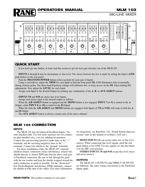
Manual-1MLM 103MIC/LINE MIXEROPERATORS MANUAL WEAR PARTS:This product contains no wear parts.MLM 103 CONNECTIONINPUTSThe MLM 103 has ten balanced Euroblock Inputs. Use only shielded cable. For best noise rejection use two-conduc-tor-plus-shielded wire, even for unbalanced operation.Connect the non-inverting (positive) audio lines to the “+”terminals, and the inverting (negative) lines to the “–”terminals. Connect the shields to the “ground” terminals.For those installations where the MLM 103’s internal shield-to-chassis connection causes interference, connect the shields directly to chassis PEM nuts directly above each pair of Euroblock connectors. Be sure to bite through the paint with the star washer and keep the shields wrapped around the audio conductors as mush as possible. For the “theoretical”best ElectroMagnetic Interference (EMI) immunity, connect the shields at both ends of the cables. (For more informationon connections, see RaneNote 110, “Sound System Intercon-nection” later in this manual or on Rane’s web site.)MONO INPUTS 1-6 can accept either mic or line level sources. When connecting line level signals, push the rear panel button in for LINE. For mic signals, be sure the button is in the MIC (out ) position.STEREO INPUTS 7/8 and 9/10 accept line level stereo and mono sources.OUTPUTSThe MLM 103’s OUTPUTS (and DIRECT OUTPUTS)are balanced. The same wiring conventions as the Euroblock Inputs apply.QUICK STARTIf you don't get any further, at least read this section to get the best gain structure out of the MLM 103.INPUTS 1 through 6 may be microphone or line level. The choice between the two is made by setting the Input’s LINE push-button on the rear panel.Push the PHANTOM POWER button (when needed) for each pair of Inputs.Using a screwdriver, adjust the TRIM for each Input so that the front panel OL LED illuminates only occasionally during extreme peaks. The three-band Equalizer settings will influence this, so keep an eye on the OL when making EQ adjustments. Now adjust the LEVEL for each Input.Assign each Input to the desired Output by pushing any combination of the A , B , or AUX ASSIGN buttons.INPUTS 7/8 and 9/10 are stereo line level Inputs.Assign each stereo input to the desired output as follows:When the A/B ASSIGN button is engaged and the MONO button is not engaged, INPUT 7 (or 9) is routed to the A Output, while INPUT 8 (or 10) is routed to the B Output.When the both the A/B ASSIGN and MONO buttons are engaged, both Inputs of 7/8 (or 9/10) will route to both the A and B Output.The AUX ASSIGN button is always a mono mix of the stereo channel.FRONT PANEL DESCRIPTIONቢ Equalizer level controls are used to contour the frequency response of the desired Input.ባ Mic/Line OUTPUT ASSIGN buttons. When the A button is engaged, the Mic/Line Input’s audio is routed to Output A.When the B button is engaged, the Mic/Line Input’s audio is routed to Output B. When the AUX button is engaged, the Mic/Line Input’s audio is routed to the Aux Output. Any (or all) of the ASSIGN buttons can be engaged simultaneously.ቤ Mic/Line INPUT LEVEL controls 1-6 determine the amount of signal to be delivered to the assigned Outputs.ብ Mic/Line OVERLOAD LED monitors the signal level before and after the Equalizer.ቦ Stereo Line OUTPUT ASSIGN buttons. When the A/B assign button is engaged and the MONO button is not engaged, Input 7 (or 9) is routed to the A Output, while Input 8 (or 10) is routed to the B Output. When both the A/B ASSIGN and MONO buttons are engaged, both Inputs of 7 and 8 (or 9 and 10) will be routed to both the A and B Output. The AUX ASSIGN button is a mono mix of the stereo Inputs.ቧ Stereo Line INPUT LEVEL controls 7/8 and 9/10 determine the amount of stereo or mono line signal to be delivered to the assigned Outputs.ቨ Stereo Line OVERLOAD LED monitors the signal levels after the Equalizer and after the line gain stage.ቩ Output Meters indicate the overall levels of Outputs A, B and the AUX Output. The Meters are “peak hold”.ቪ A, B and AUX OUTPUT LEVEL controls set the Output Level for A, B and AUX Outputs.ቫ POWER LED lights whenever adequate power is applied to the unit.Manual-2Manual-3REAR PANEL DESCRIPTIONቢ MIC/LINE INPUT TRIM controls 1-6 adjust the input gain of the Mic/Line Inputs. The gain range for Mic level is 15 to 60 dB. The gain range for Line level is 0 to 12 dB.ባ LINE/mic INPUT buttons 1-6 switch the sensitivity and input impedance for either a microphone or line input. Mic level is selected when the button is in the “out” position. Line level is selected when the button is in the “in” position.ቤ MIC/LINE INPUT connectors 1-6 are balanced Euroblocks that connect either microphone or line signals.ብ PHANTOM POWER button applies 12 volt phantom power to each pair of Mic/Line Inputs.ቦ STEREO LINE INPUT connectors 7/8 and 9/10 are pairs of balanced Euroblock connectors, to accommodate stereo or mono line level signals.ቧ PRE/post MIX LEVEL DIRECT OUTPUT buttons . When this switch is in the “in” position, the Direct Output signal is not affected by the Input’s Level control. When this switch is in the “out” position, the Direct Output signal is affected by the Input’s Level control.ቨ DIRECT OUTPUTS are balanced Euroblocks that directly connect each Mic/Line Input signal to other audio devices as needed. These Direct Outputs are post-Equalizer.ቩ A, B and AUX OUTPUT connectors. One 6-post balanced Euroblock connects the A mix and the B mix to other audiodevices as needed. The other 3-post balanced Euroblock connects the AUX mix to other audio devices as needed.Manual-4©Rane Corporation 10802 47th Ave. W., Mukilte o WA 98275-5098 TEL (425)-355-6000 FAX (425)-347-7757 WEB 104195MLM 103 OPERATIONMONO MICROPHONE/LINE LEVEL INPUTS 1-6The rear-panel MIC/LINE INPUT TRIM adjusts the input gain of these Inputs, before the front panel LEVEL controls.When an Input’s LINE/mic button is in the “out” position (Mic Level), the gain range is 15 to 60 dB. When an Input’s LINE/mic button is in the “in” position (Line Level), the gain range is 0 to 12 dB.First, input some “loud” source material (like a pop metal or disco CD, give a kid a mic, etc.) Then, using a screwdriver,adjust the TRIM for each Input so that the front panel OL LED illuminates only occasionally during extreme peaks. The 3-band Equalizer settings will influence this, so keep on eye on the OL when making EQ adjustments.Push the PHANTOM POWER button (when needed) for each pair of Inputs. If the LINE/mic button is engaged (Line Level), Phantom Power is automatically defeated for that Input. The PHANTOM POWER button activates 12 volts which is sufficient power for all but the most esoteric condenser mics. If in doubt, check the manufacturer’s microphone specs.Assign each Input to the desired Output by pushing any combination of the A, B or AUX ASSIGN buttons.The LEVEL of each Input can now be adjusted as needed without danger of blowing your speakers, or scaring the neighbors, whichever you deem worse.STEREO LINE LEVEL INPUTS 7/8 and 9/10When a stereo source (CD, DVD, cassette, etc.) isconnected to Inputs 7/8 (or 9/10), the routing is as follows:When the A/B ASSIGN button is engaged and the MONO button is not engaged, INPUT 7 (or 9) is routed to the A Output, while INPUT 8 (or 10) is routed to the B Output.When both the A/B ASSIGN and MONO buttons are engaged, a mono mix of INPUTs 7/8 (or 9/10) will be routed to both the A and B Outputs.The AUX ASSIGN button is always a mono mix of the stereo channel.OUTPUT LEVELSAfter all of the Mic/Line and Stereo Input Levels have been adjusted and routed, adjust the OUTPUT faders so the Meters peak average around 0 to +2.。

AMBE-1000 用户手册版本1.0南京梧桐微电子中心1. 概述根据对语音构成的分析,应运而生了多种对音频信号的压缩编码算法,如CELP、RELP、VSELP、MP-MLQ、LPC-10、MBE等,它们通过不同的算法,实现对音频信号的压缩。
这些压缩编码算法的压缩率、语音质量各有所长,其中美国DVSI(Digital Voice System Inc)公司提出的先进多带激励AMBE (Advanced Multi-Band Excitation)压缩编码算法是其中的杰出代表。
AMBE是基于MBE技术的低比特率、高质量语音压缩算法,具有语音音质好和编码速率低等优点,AMBE-1000是一款高性能多速率语音编码/解码芯片,语音编码解码速率可以在2400~9600bps之间以50bits的间隔变化,即使在2400bps的时候,仍能保持自然的声音质量和语音可懂度。
在芯片内部有相互独立的语音编码单元和解码单元,可同时完成语音的编码和解码任务。
并且所有的编码和解码操作都能在芯片内部完成,不需要额外的存储器。
这些特性使它非常适合于数字语音通信、语音存储以及其它需要对语音进行数字处理的场合。
2. AMBE-1000应用设计的概述2.1 基本操作AMBE-1000最基本的组成部分就是一个编码器和一个解码器,两者相互独立。
编码器接收8KHZ采样的语音数据流(16bit线性,8bit A律,8bit u律)并以一定的速率输出信道数据。
相反,解码器接收信道数据并合成语音数据流。
编码器和解码器接口的时序是完全异步的。
AMBE-1000采用A/D-D/A芯片作为语音信号的接口。
输入输出的语音数据流的格式必须是相同的(16bit 线性的,8bit A律,8bit u律),信道接口采用8位或16位的微控制器。
芯片可选择的功能包括回声抵消,VAD(语音激活检测),电源模式,数据/前向纠错率的选择等,这些功能由外围管脚或输入到解码器的命令帧来决定。

TROUBLE SHOOTING..........................................................13ADJUSTING & TUNING........................................................12PLANNING & MOUNTING YOUR SYSTEM................................9 ~10WIRING DIAGRAM..............................................................11 CONTROLS & FUNCTIONS...................................................FEATURES & SPECIFICATIONS .............................................TABLE OF CONTENTSINTRODUCTION.................................................................234 ~ 8INTRODUCTIONAmplifier's provide high-performance sound reinforcement for you'rmobile audio equipment. The Multi-Mode bridging capabilities allowflexibility in hosting several different speaker configurations.To achieve optimum performance, it is highly recommended that you read this Owners Manual before beginning installation.2FEATURESSPECIFICATIONSIDI (Intelligent Distress Indicator)gives a visualindication of the amplifier's protection statusFully regulated MOSFET power supplyPWM circuitryTri-guard amplifier protectionPlatinum RCA inputs and outputsBi-linear selectable crossovers for inputs and outputs (Hi/Full/Low)Continuously variable high and low-pass crossoversSubwoofer equalizer control switchViable phase shift control (0 - 180 degree)OEM floating ground inputPlatinum 4-gauge power connectorsTri-mode operationIncludes remote bass boost control (PCX2.350/2.440/2.540/2.700/5.600)This control adjusts the amplifier's input sensitivity. Input sensitivity is variable from200 Millivolts to 8 volts. Clockwise increases sensitivity. Counterclockwise decreasessensitivity. The amplifier can be driven to full power with a wide range of signal levels.A lower signal level will require increased sensitivity for full power. A higher signal levelwill require decreased sensitivity. Av oid setting sensitivity lower than necessary as this would introduce unwanted distortion.This control is used to set the desired low pass frequency (50 ~ 150HZ).The filter acts to cut-off frequencies above the set-point. In general, the selectedfrequency should closely match the resonant frequency of the speaker box.By using the bass boost function, bass notes at 35Hz - 80Hz are emphasized as much as 18dB.PHASE SHIFT SWITCH (0 AND 180 DEGREES):Allows you to change the phase of your subwoofer from 0 to 180 degrees to helpcompensate for timing differences between drivers.6Variable Subsonic Filter (15Hz - 40Hz) :The Subsonic filter will roll off all of the unwanted frequencies below 15Hz - 40Hz.This will allow the amplifier to use that wasted power on the audible bandwidth.These inputs are for signal cables from the source. Always use high quality shieldedRCA cables.the first amplifier, then using the line out RCA jacks as the feed to the next amplifier.Adjust the crossover for your chosen installation method.LOW: Low pass filter-only bass tones(50Hz-150Hz)go to speakers. Use with woofer or sub-woofer . FULL: No filter-all tones go to speakers. Use with full-range speakers, or with external crossovers. HIGH: High pass filter-blocks very low tones(50Hz-600Hz)from the speakers.CH4Due to the power requirements of the Amplifier, this connection should be made directly to the positive(+) terminal of battery. For safety measure, install an in-line fuse Holder (not included) as close to the battery positive(+) terminal as possible with an ampere rating ; not to exceed total value of fuses in Amp.PWR(Power): This GREEN LED will illuminate when the amplifier is turned "ON".If it fails to illuminate, check the power connections to the Amplifier and fuses.PROT(Protection): The amplifier protection circuitry will disable the amplifier if input overload, short circuit or extremely high temperature conditions are detected. When the protection mode is in operation, the LED indicator on the side panel will be illuminated, indicating the amplifier has gone into a self-preservation mode.If you observe that the Protection LED is lit, please check the system carefully to determine what has caused the protection circuit to engage. The amplifier can be reset by turning the remote power off and then on again. If the amplifier shut down due to a thermal overload condition, please allow it to cool down before restarting. If the amplifier shut down becauseof an input overload or short circuit, be sure to repair these conditions before attempting to power up the amplifier again.Controls & FunctionsThe mounting position of your Amplifier will have a great effect on its ability to dissipate the heat generated during normal operation.Under normal conditions, the heatsink will dissipate sufficient heat to avoid thermal shutdown. However please do not install the amplifier in a wooden box or similar device as this will prevent heat dissipation into the atmosphere.Temperatures in car trunks have been measured as high as (155'F) in the summer time. since the thermal shut-down point for the amplifier is (158'F) it is easy to see that it must be mounted for maximum cooling capability. To achievemaximum advantage of convection air flow in an enclosed trunk, mount the amplifier in a horizontal position.Cooling requirements are considerably relaxed when mounting inside the passenger compartment since the driver will not often allow temperatures to reach a critical point. Floor mounting under the seat is usually satisfactory as long as there is at least1 inch of clearance (2.54 cm) above the Amplifier's fins for ventilation.A. Select a suitable location that is convenient for mounting, is accessible for wiring. And has ample room for air circulation and cooling.B. Use the amplifier as a template to mark the mounting holes. Remove the Amplifier and drill holes. Use extreme caution, inspect underneath surface before drilling!C. Secure the Amplifier using the screws provided.Mono modeTri modeTuning on the AmplifierAdjusting The Audio LevelThe amplifier automatically turns on a few seconds after you turn your vehicle's ignition switch to ACC or ON or turn on your auto sound system, depending on how you wired the system. The POWER indicator on the top of the amplifier lights when the amplifier is on.Important : Your amplifier requires 30 amps or more of power from your vehicle's battery during operation. To protect y our battery from discharging, do not operate the amplifier unless your vehicle is running.FREQUENCY (Hz)10-30dB -20dB-10dB0dB +10dB+20dB FREQUENCY RESPONSER E S P O N S E (d B )BASS BOOST ON4535 80 100 500 1K 5K 20K 50KNOTE: Raising the Bass frequency allows higher frequencies to reach the bass speakerswhile blocking lower frequencies from midrange speakers. Lowering the Bass frequencies allows lower frequencies to reach the midrange speakers whileblocking higher frequencies from bass speakers.For the best performance, you must set GAIN (MIN / MAX) on the side of the amplifier to adjust the level of the audio signals that enter the amplifier .1. Use a screwdriver to turn GAIN (MIN / MAX) fully counterclockwise to MIN.2. Turn the auto sound system's volume control to about one-third of its full range.3. Adjust GAIN (MIN / MAX) to a comfortable listening level.4. Turn up the auto sound system's volume control until the sound begins to distort. Then immediately turn the volume down to a point just before where the distortion began.Caution : Never turn up the auto sound system's volume control more than needed to adjust the audio level, more than two thirds of its maximum volume.5. Adjust GAIN (MIN / MAX) until the sound is at the maximum level you want the amplifier to produce.6. Adjust the auto sound system's volume control to a comfortable listening level.Trouble ShootingSYMPTOMS NO SOUNDAMP NOTSWITCHING ON NO SOUND IN ONE CHANNELAMP TURNING OFF MEDIUM /HIGH VOLUME PROTECTIONLAMP ON Is the power Is the Diagnostic LED illuminated? (YES) No power to power wire Repair power wire or connections. No power to remotewire with receiver onCheck connections to radio. Burnt or broken fuse Check Speaker Leads Inspect for short circuit or an open connection.Reverse Left and Right RCA inputs to determine if the problem isoccurring before the amp.Be sure proper speaker load impedance recommendations are observed.(If you use an ohmmeter to check speaker resistance, pleaseremember that DC resistance andAC impedance may not be the same.)Check Audio LeadsCheck Speaker loadimpedanceShut down Turn radio down Wait for AMP to coolSpeaker wires shorted Separate speaker wires andinsulateCheck for speaker short or amplifier overheating.Check all fuses to amplifier . Be sure Turn-on lead is connected Check signal leads. Check gain control. Check Tuner/Deck volume level. Clean contacts on fuse holders.LED illuminated?(NO) CHECKREMEDY Replace fuse。
AMBE2000用户手册概述DVSI的AMBE2000声音编码器是一个非常灵活的,高性能功能的,独立的语音压缩编码器。
在低数码率的环境下它能提供比较好的声音质量。
在AMBE建立的声音压缩软件算法的标准下它提供了一个实时全双工的结果。
DVSI的获得的AMBE声音压缩专利技术已经被证明比CELP,RELP,VSELP,MELP,ECELP,MP-MLQ,LPC-10等等其他有竞争力的技术做的更好。
很多改进已经表现出它的能力能够达到半数据码率下的蜂窝系统的性能。
在世界范围内AMBE声音压缩算法被当成一个软件使用,包括下一代数字移动电话通信系统。
AMBE-2000声音编码器芯片在语音的选择和前向错误预测数据速率方面提供了一个高度的灵活性。
最终码率从2.0kbps到9.6kpbs内用户可以以50bps为数据增量设置参数。
通常对于较高出错码率通道,用户将分配一个速率的较高比例的部分给前向错误预测编码。
在速率低如 2.0kbits/sec时AMBE-2000声音编码器保留了自然的声音质量和声音的可理解性。
AMBE算法的低复杂性使它可以完全完整的组成一个低消耗,低能量完整芯片,那就是AMBE-2000声音编码芯片。
AMBE-2000提供了和AMBE-1000类似的特点,允许它能和已经为AMBE-1000设计好的系统合并成一体并且能和DVSI公司的其他产品一起使用(说白了就是和DVSI公司的其他产品有很好的兼容性)。
AMBE-2000提供了改良的性能比增强了比如在4.0kbps损耗通路中的语音质量还有前向错误预测卷积编码的模式。
出了这些增强的元素,AMBE-2000还利用了一个除了可变码率接口和FEC选择接口外的可控接口。
1.2优点较好的声音质量低消耗,无需外部记忆要求,消除少量的错误和后台噪声,可变的数码率,从2.0kbps到9.6kbps,可变的FEC速率从50bps到7.2kbps,非常低的功耗(在3.3V下65mW,深睡眠状态下11mW)使简单的芯片处理方法更紧密外貌高质量的低速率语音编码DVSI公司完整的两部分的AMBE的声音编码支持在2.0kbps至9.6kpbs以50bps增量的速率改变用户可以选择前向错误预测的编码速率工程项目解码16阶软判断解码声音的活动探测/平滑噪声干扰16毫秒回声消除分立的声音检和产生低能量模式极小的算法处理延时AMBE-2000的用户手册4.9多音双频的预测及在北美通话特色下的改进1.3典型的应用卫星通信数字无线电通信固定电话通信蜂窝电话和PCS声音的复用声音的传送多媒体应用、第二章2.1基本原理在它最简单的模式下,AMBE-2000可以看成是两个独立的原件组成的部分,编码器和译码器。
VAMP2.0中文说明书还是有很多人对于V-Amp 2.0摸不清头绪,我来整理一下在网上搜集到的说明书和以前自己的经验,希望对大家有帮助。
1、介绍恭喜!阁下购买的V-AMP2为V-AMP虚拟吉它扩音器的改良产品。
我们对其进行改进的最终目的是通过“物理模拟”并结合最新的DSP效果器方式以产生出值得信赖的经典扩音器的音色。
与其上一代产品--V-AMP相比,V-AMP2具有许多优势:被模拟的扩音器数量增加了一倍;五个可进行全局调整的操作模式;由于带有前级旁路(Preamp Bypass),你还可以将该设备单纯作为的效果器来使用。
我们再次直面研发产品带来的挑战。
当然它仍有可能成为未来一段时间人们的话题。
V-AMP2是一款多功能的产品,它既可以在绝不造成任何信号传输问题的情况下,为您带来32款值得信赖的、甚至是特殊的扩音器的音色,还可以为您提供由多效果处理器技术带来的各种声音。
简而言之,V-AMP2给您的是一个声音工具,里面包含了各种当今音乐人梦寐以求的元素。
BEHRINGER是一家由从事专业录音棚技术发展而来的公司。
多年以来,我们已经成功地开发了多种用于录音棚及演出现场的产品,包括麦克风及各类标准机架设备(如压缩器、增强器、噪音门、电子管处理器、耳机放大器、数字效果设备及DI盒等)、监听器、调音台以及专业现场、录音棚混音器。
我们已将所掌握的全部技术融入V-AMP2中。
灵活性是音乐领域中至关重要的一环。
一个现代吉它手不仅需要演奏多种音色,还需要有适应不同演奏环境(家庭录音、录音棚、现场演出)的能力。
因此,庞大的扩音器堆阵已经成为过去。
V-AMP2融尽可能多的功能于一身,而且设置及携带非常方便,同时很容易就可以掌握。
内置的EPROM很方便进行替换,从而使得V-AMP2可以引领时代。
也就是说我们将听取您的建议,并且不断地对新的算法进行研究。
然后放在互联网上供您免费下载,这样即使是在将来,V-AMP2也一样不会落伍。
User ManualTable of ContentsIntroduction4 Quick Start4 Features4 In the Box5 System Requirements6 PC6 Mac6 iOS6 Safety Instructions and Precautions7 Hardware Connections8 Front Panel8 Rear Panel9 Controls10 Interactive Touch Panel Display10 Meter Modes and Levels10 Getting Started11 Audio Driver Installation11 Mac and iOS devices11 Windows systems11 Setting Up the Interface12 Setting the Output/Phones Level12 Out/Phones Meter Modes13 Setting Up Inputs13 Assigning Input Modes13 Input Display States14 Setting Input Levels14 Input Meter Modes15 Direct Monitoring15 How to Enable Direct Monitoring15 Working with Direct Monitoring: Mono/Stereo Modes15 Working with Direct Monitoring:Adjusting the Input/USB Balance16 Additional Notes About Direct Monitoring17 Headphone Source Selection17 Troubleshooting17 Reference: Audio Specifications19Digital Performance19 Microphone Inputs19 Line/Instrument Inputs(Balanced Input)19 Line/Instrument Inputs(Single Ended Input)19 Line Outputs19 Headphone20 Reference:Direct Monitoring States21 Contact iConnectivity41 Warranty41IntroductionThank you for purchasing the Connect AUDIO2/4Audio/MIDI Interface.Your Connect AUDIO2/4is a mem-ber of the most flexible interface line available,with unique features that make it ideal for the stage,studio, and club.Quick StartThe Quick Start Guide included in your Connect AUDIO2/4box is a handy primer for getting up and run-ning with this versatile interface.You can also jump to the Getting Started section of this manual to start using the Connect AUDIO2/4right away.FeaturesFeatures of the Connect AUDIO2/4include:l High-resolution audio: up to24-bit/96kHz AD/DA conversionl Direct Monitoring capability that allows you to monitor input sources without computer latencyl Interactive touch panel display for touch-control of all interface functionalityl USB audio and MIDI class-compliantl USB bus-poweredl Two XLR-¼"combination mic/line/instrument analog inputs,with+48V phantom power toggle and line/instrument mode selectionl Two¼"TRS balanced analog outputsl¼"stereo headphone output with independent mix controll5-pin MIDI DIN in/outl+48V phantom power for condenser microphonesIn the Box2/4Audio/MIDI interfacel The Connect AUDIO2/4to a Mac or PC l(1)USB cable for connecting your Connect AUDIO2/4Quick Start Guidel Connect AUDIOSystem RequirementsVisit /support for the most up-to-date compatibility requirements,as these are sub-ject to change.PCl Windows7or higherl(1)free USB portMacl Mac OSX10.8or higherl(1)free USB portiOSl iOS6.0or higherl Apple Lightning-to-USB3Camera AdaptorMac and the Mac logo are trademarks of Apple Inc.,registered in the U.S.andother countries.Connect AUDIO2/4and iConnectivity are trademarks of iKingdom Corp.Features of this product are protected under patent pending.For more details,refer to:/patents.Safety Instructions and PrecautionsHardware ConnectionsFront Panel1.Stereo headphone jackbination XLR and1/4"analog inputs.Your Connect AUDIO2/4accepts mic,instrument,and line-level input sources and can be configured for+48phantom power and/or high/low imped-ance across one or both inputs.3.Interactive touch panel display.The Connect AUDIO2/4's touch panel makes it easy to selectinput modes and headphone source,adjust input/output levels,and enable and configure Direct Mon-itoring.4.Rotary Control Dial for setting input/output levels/gain and adjusting the balance in Direct Mon-itoring mode.Learn more about the Direct Monitoring capabilities of your new Connect AUDIO2/4 interface.Rear PanelB Device Port: Use the included USB cable to connect your interface to a PC or Mac device run-ning your Digital Audio Workstation host software.An iOS device can be connected using the Apple Lightning-to-USB3Camera Adaptor.2.MIDI In/Out:Accepts5-pin MIDI DIN connections for standard MIDI hardware.MIDI is transmittedat the standard MIDI rate of31.25Kbps3.Analog Output Jacks1–2: ¼"balanced TRS outputs for connecting to powered monitors or a ste-reo amplifier with attached speakers.Output levels are capable of reaching+12dBu.Exercise cau-tion when setting output levels to avoid potentially overloading equipment in the downstream signal path.Note: Do not connect+48V phantom power to the analog output jacks as this could damage the output circuits.4.Chassis Grounding Screw:Use this grounding screw if grounding issues occur when connectingmultiple electronic devices.ControlsInteractive Touch Panel DisplayThe Connect AUDIO2/4’s Interactive Touch Panel Display is a capacitive touch panel that provides the fol-lowing features:l Eight touch zones for intuitive control over viewing and adjusting Inputs and Outputs,Direct Mon-itoring,and enabling+48V phantom power for condenser microphonesl Dual8-stage LED meters and independent metering modes for select functionsl A Rotary Control Dial for setting gain/levels and adjusting the balance between inputs and USBaudio when in Direct Monitoring mode.The Rotary Control Dial also performs auxillary functions, such as:o Commiting Gain Settings to Memory: While in Gain Set mode,press the dial once to com-mit the current settings to memoryo Powering down the unit: Press and hold the Rotary Control Dial until both meter columns show red and yellow LED indicators at the top of the display.Then,release the Dial to powerthe unit OFF.From the OFF state,press the Dial once to power the unit back ON.Note:The Rotary Control Dial is continuous and can make fine or coarse adjustments depending on how quickly you rotate the dial.Fine adjustments are recommended if there is a risk of signal overload.Meter Modes and LevelsThere are two primary meter display modes when selecting In,Out,or Phones on the panel.Successive touches of the In,Out,or Phones buttons toggle between:l Signal Level mode,indicated by the green LED.The LED meters display VU(signal level)and will react to the input signal in real time.l Gain Set mode,indicated by the red LED.The LED meters display the gain setting and respond to clockwise or counter-clockwise motion of the Rotary Control Dial.A third meter mode is activated when Direct Monitoring is selected on the panel.Refer to the Direct Mon-itoring section of this manual for more information.Getting StartedAudio Driver InstallationMac and iOS devicesAn audio driver is not required for Mac and iOS devices.The Connect AUDIO2/4is USB class-compliant, enabling it to be recognized automatically by Mac OS X and iOS systems and allowing applications to pass audio and MIDI as soon as the Connect AUDIO2/4interface is connected.Windows systemsGo to the iConnectivity support page and download the audio driver installer applicable to your Windows version.Then,follow these steps:1.Double-click on the installer executable file to launch the installer.Depending on your Windows ver-sion,it may be necessary to select the installer file and open as Admin.2.Follow the onscreen prompts to install the audio driver to the default destination folder.When theinstaller completes,click Finish to exit the wizard.Setting Up the Interface1.Connect the interface to your PC,Mac,or iOS device.(Note that a separate Apple Lightning-to-USB3Camera Adaptor is required for iOS devices)2.Verify that the interface is powered ON:Your Connect AUDIO2/4is USB bus-powered anddoes not require an external power supply.Once connected,the default indicator lights on the Touch Panel Display will illuminate,indicating that your Connect AUDIO2/4is powered ON and ready for use.3.Check for firmware updates:Go to the iConnectivity support page,download and install the iCon-fig Configuration and Control software,and open iConfig.iConfig will check the firmware version of your Connect AUDIO2/4and prompt you to update your firmware if a newer version is available.iConfig also lets you view information such as the serial number and hardware version of your unit.Note:We recommend updating to the latest firmware,but you can skip this step and return to it later, if you prefer.4.Enable the interface in your DAW: In your DAW,select the Connect AUDIO2/4as the Input andOutput device.Setting the Output/Phones LevelOnce you have hooked up the Connect AUDIO2/4to your device and enabled it in your DAW host soft-ware,follow these steps to set the Ouput/Phones level:1.Set up a track in your DAW that contains audio and route it to channels1/2of theConnect AUDIO2/4.2.Verify that the Phones button LED is green,indicating that channels1/2are selected.3.Touch Out or Phones,according to your monitoring setup;either amplifier/speakers or headphones.Touch once to enable Signal Level metering mode(green LED).Touch twice to enable Gain Set metering mode(red LED).Refer to the Out/Phones Meter Modes section below for more information about meter modes.4.Verify that the1and2LED indicators in the upper-left section of the panel are lit.In Out/PhonesMode,these buttons represent the stereo linked output.In Out Mode you can select1or2individually and adjust each output separately,if you prefer.5.Play the audio track in your DAW and move the Rotary Control Dial slowly until you begin to hearaudio in your speakers or headphones.Continue adjusting the dial to increase or decrease the level as desired.Out/Phones Meter ModesThere are two meter display modes.Pressing the Out or Phones buttons multiple times allows you to toggle between:l Signal Level mode,indicated by the green LED.The LED meters display VU(signal level)and will react to the input signal in real time.l Gain Set mode,indicated by the red LED.The LED meters display the gain setting and respond to clockwise or counter-clockwise motion of the Rotary Control Dial.Setting Up InputsAssigning Input ModesWith your interface connected,and your DAW open with the Connect AUDIO2/4selected as the Input/Out-put device,follow these steps to set up an audio input source and pass the audio signal to your DAW from your Connect AUDIO2/4:Dynamic Mics,Instruments or Line-Level Sources1.Touch48V/Inst twice,to set Inst as the Input Mode.The indicator light will display red.2.Touch1,2or both to assign the Inst Input Mode to an input.The input indicator light will turngreen for inputs to which Inst mode has been assigned.Figure1:Input Assign mode;Inst mode assigned to Input2Condenser Mics1.Touch48V/Inst once,to set+48V as the Input Mode.The LED indicator will display green.2.Touch1,2or both to assign the+48V Input Mode to an input.The LED indicator light will dis-play green for inputs to which+48V mode has been assigned.Figure2:Input Assign mode;48V mode assigned to Input1Input Display Statesl When you press the48V/Inst button so that48V is selected,inputs that display green are assigned to48V mode.l When you press the48V/Inst button so that Inst is selected,inputs that display green are assigned to Inst mode.Note: Input audio is temporarily muted when48V power is turned ON or OFF.Allow a few moments for the audio path to be re-enabled when engaging or dis-engaging the48V function.Setting Input LevelsWith input modes assigned,follow these steps to set input levels:1.Touch the In button once to enable Signal Level metering mode(green LED).Touch the In buttonagain to enable Gain Set metering mode(red LED).Refer to the Input Meter Modes section below for more information about meter modes.2.Touch1and/or2to select either or both inputs.3.Turn the Rotary Control Dial to raise or lower the level of the selected inputs as you generatesource audio.Input Meter ModesThere are two meter display modes.Pressing the In button multiple times allows you to toggle between: l Signal Level mode,indicated by the green LED.The LED meters display VU(signal level)and will react to the input signal in real time.l Gain Set mode,indicated by the red LED.The LED meters display the gain setting and adjust toclockwise or counter-clockwise motion of the Rotary Control Dial.The1and2LEDs will turn red to indicate clipping any time the audio signal exceeds acceptable levels. These clipping indicators will appear regardless of what mode the Touch Panel is currently operating in.Direct MonitoringDirect Monitoring(DM)is a key feature of the Connect AUDIO2/4.It enables you to monitor audio input dir-ectly from the Connect AUDIO2/4interface without the latency introduced when monitoring the same sig-nal through your DAW.DM offers Mono and Stereo modes and provides Rotary Dial control to balance the level between your audio input(s)and the computer output.How to Enable Direct Monitoring1.Touch Direct on the Touch Panel.The Direct LED indicator will display green and initialize in Monomode by default.2.Select the inputs(1,2,or both)to be monitored.e the Rotary Dial to adjust the balance between audio from the input(s)and USB audio. Working with Direct Monitoring: Mono/Stereo ModesWhen you first initialize DM,it will be enabled in Mono Mode by default.If both inputs are enabled,there will be no panning between audio sources.Toggling DM to Stereo Mode allows you to auto-pan Inputs1 and2to the Left and Right sides of the stereo spectrum and enables clearer monitoring of multiple sources.With Direct selected on the Touch Panel Display,Direct Monitoring can be toggled to Stereo Mode by touching the48V/Inst button.The Direct LED indicator will change from green to red,indicating that DM is now operating in stereo.Figure3:Toggling DM from Mono to Stereo ModeRefer to the Direct Monitoring States reference section of this manual to view all the possible DM con-figurations and their respective audio routing.Working with Direct Monitoring:Adjusting the Input/USB BalanceWith Direct Monitoring enabled,the meters on the Touch Panel Display toggle to show the respective Input(left meter column)and USB(right meter column)levels.Moving the Rotary Control Dial adjusts the balance between the two.l Rotate the dial clockwise for more USB signal in the monitor mixl Rotate the dial counter-clockwise for more Input signal in the monitor mixFigure4:Adjusting the Direct Monitoring balanceAdditional Notes About Direct Monitoringl The Direct Monitoring LED indicator will change to orange any time you press the In or Out buttons to make adjustments.This indicates that Direct Monitoring is still enabled,but not available for edit-ing.Headphone Source SelectionHeadphone Source Selection is a feature of the Connect AUDIO2/4that allows you to easily switch between the computer output channels being monitored on the headphones.One touch switches the headphone source between channels1/2and channels3/4.Note that channels1/2are always routed to the analog outputs on the back panel,regardless of the headphone source selec-tion.To change headphone sources,press the1/2_3/4button on the Touch Panel.l indicates that output pair1/2is selectedl indicates that ouput pair3/4is selectedTroubleshootingI don't hear any sound from the speakers or headphones connected to the interfaceMake sure that you have set up output levels on the unit.Verify that the output pair over which your DAW is transmitting audio is selected on the Touch Panel.I’ve turned on direct monitoring but I'm only hearing the computer output,not the analog input.Verify that you have selected one or more of the analog inputs for monitoring.If neither input is selected, you will only hear the computer output.Refer to the Direct Monitoring section for more information.I have a device connected to the MIDI DIN connectors,but I'm not seeing it on my computer.Verify that the MIDI DIN connections are not reversed.MIDI Out on the controller should be connected to MIDI In on the interface,and vice-versa.The interface is not powering up or is turning ON and OFF again.Verify the USB cable and the USB port power.The USB port may not be providing sufficient power.The cable may be too long or of insufficient quality to support the power supply current.Reference: Audio SpecificationsDigital Performancel24bit resolutionl A-D Dynamic Range:102dB(fs=48kHz,20Hz20kHz,A-wt,24bit)l D-A Dynamic Range:104dB(fs=44.1kHz,20Hz20kHz,A-wt,24bit)l Supported sample rates:44.1kHz,48kHz,88.2kHz,96kHMicrophone Inputsl Gain:060dB(1dB steps)l Frequency response(flatness):20Hz20kHz(+/-0.2dB)l SNR:+104dB(1kHz,1Vrms,22Hz-22kHz,A-wt,lowest gain)l THD+N:-90dB(1kHz,1Vrms,22Hz-22kHz,A-wt,lowest gain)Line/Instrument Inputs(Balanced Input)l Attenuator:20dB(fixed)l Impedance:800kOhms(Hi-Z),45kOhms(Lo-Z)l SNR:+106dB(1kHz,2Vrms,22Hz22kHz,A-wt)l THD+N:-102dB(1kHz,2Vrms,22Hz22kHz,Unweighted)l Maximum Input Level:16Vrms,26dBu,24dBV(1kHz,22Hz-22kHz,A-wt,1%l THD+N,SNR=+124dB)Line/Instrument Inputs(Single Ended Input)l Attenuator:20dB(fixed)l Impedance:800kOhms(Hi-Z),45kOhms(Lo-Z)l SNR:+106dB(1kHz,2Vrms,22Hz22kHz,A-wt)l THD+N:-89dB(1kHz,2Vrms,22Hz22kHz,A-wt)l Maximum Input Level:8Vrms,20dBu,18dBV(1kHz,22Hz-22kHz,A-wt,1%THD+N,SNR= +118dB)Line Outputsl Maximum Output Level:3.1Vrms,12dBu,9.8dBVl Frequency response(flatness):20Hz20kHz(+/-0.1dB)l SNR:+118dB(1kHz,22Hz-22kHz,A-wt)l THD+N:-108dB(1kHz,22Hz-22kHz,A-wt) Headphonel Frequency response(flatness):20Hz20kHz(+/-0.1dB) l SNR:+119dB(1kHz,22Hz-22kHz,A-wt)l THD+N:-116dB(1kHz,22Hz-22kHz,A-wt)l Power into30Ohm channel:34mW per channelReference:Direct Monitoring StatesThe diagrams below illustrate the signal flow for each of the Connect AUDIO2/4's respective Direct Mon-itoring,Input,and Headphone configurations.In the Connect AUDIO2/4's device initialization state,Direct Monitoring is Set to OFF and configured in mono mode with no inputs selected.Contact iConnectivity*************************+1403.457.1122Monday to Friday9:00am to5:00pm(Mountain Time)iConnectivity#100,92526th Street NECalgary,AB T2A6K8CanadaWarrantyiConnectivity warrants to the original purchaser that this unit is free of defects in materials and work-manship under normal use and maintenance for a period of one(1)year from the date of original pur-chase.The warranty applies only to registered iConnectivity users that register their product(s)within fourteen(14)days of time of original purchase.To register iConnectivity products,visit . If the unit qualifies for warranty service during the one(1)year period,it will be repaired,or replaced,at iConnectivity’s option,at no charge,when returned prepaid to the iConnectivity Technical Service Center with proof of purchase–the sales receipt may be used for this purpose.Installation labor is not covered under this warranty.All replacement parts,whether new or re-manufactured,assume as their warranty period for only the remaining time of this warranty.This warranty does not apply to damage caused by improper use,acci-dent,abuse,improper voltage service,fire,flood,lightning,or other acts of God,or if the product was altered or repaired by anyone other than iConnectivity Technical Service Center.Consequential and incid-ental damages are not recoverable under this warranty.Some regions do not allow the exclusion or limitation of incidental or consequential damages,so the above limitation or exclusion may not apply.This warranty gives you specific legal rights,and you may also have other rights,which vary from state to state.No portion of this warranty may be copied or duplicated without the expressed written permission of iConnectivity.THIS WARRANTY IS NOT TRANSFERRABLE.For warranty service,please contact iConnectivity via the contact information presented in the section above.41Connect AUDIO2/4User Manual。
主面板用户手册Ample Bass A北京博声音元科技有限公司目录1乐器面板 (4)1.1乐器面板概述(O VERVIEW OF I NSTRUMENT P ANEL) (4)1.2预制文件读取/保存(S AVE/L OAD P RESET) (4)1.3卷弦器(A LTERNATE T UNER) (5)2主面板 (6)2.1主面板概述(O VERVIEW OF M AIN P ANEL) (6)2.2吉他技巧与复音连奏(A RTICULATIONS &P OLY L EGATO) (7)2.2.1技巧列表(Articulation List) (7)2.2.2标准音与重勾弦-Sustain & Pop (7)2.2.3自然泛音(Natural Harmonic) (8)2.2.4手掌闷音(Palm Mute) (8)2.2.5无头滑音与无尾滑音(Slide In from below & Slide Out downwards) (8)2.2.6连奏滑音(复音连奏) - Legato Slide (Poly Legato) (9)2.2.7击钩弦(复音连奏)- Hammer-On & Pull-Off (Poly Legato) (12)2.2.8拍弦(Slap) (14)2.2.9双演奏法功能(Doubled Keyswitches) (14)2.3话筒模式(M IC M ODE) (14)2.4变调夹(C APO) (14)2.5指法逻辑切换(C APO L OGIC M ODE) (14)2.6自动打品(A UTO B UZZ) (15)2.7丰富的左手演奏噪音(R ICH F RET S OUND) (15)2.8演奏模式切换(P LAY M ODE S WITCH) (15)2.9自动连奏模式切换(A UTO L EGATO M ODE S WITCH) (15)2.10空弦优先(O PEN S TRING F IRST) (16)2.11颤音(V IBRATO W HEEL) (16)2.12弦指定与把位指定(S TRING F ORCE &C APO F ORCE) (16)2.12.1弦指定(String Force) (16)2.12.2把位指定(Capo Force) (16)2.13效果音组(FX S OUND G ROUP) (17)2.14八度演奏法(O CTAVE P ATTERN) (17)2.15音重复键(N OTE R EPEATER) (18)2.16延音踏板开关(H OLD P EDAL T OGGLE) (18)1乐器面板1.1乐器面板概述(Overview of Instrument Panel)2. 预制文件读取/保存(Save/Load Preset)3. 卷弦器(Alternate Tuner)4. 把位显示(Capo Force Display)5. 弦指定显示(String Force Display)1.2预制文件读取/保存(Save/Load Preset)显示当前使用的预置。
AMBE-1000 用户手册版本1.0南京梧桐微电子中心1. 概述根据对语音构成的分析,应运而生了多种对音频信号的压缩编码算法,如CELP、RELP、VSELP、MP-MLQ、LPC-10、MBE等,它们通过不同的算法,实现对音频信号的压缩。
这些压缩编码算法的压缩率、语音质量各有所长,其中美国DVSI(Digital Voice System Inc)公司提出的先进多带激励AMBE (Advanced Multi-Band Excitation)压缩编码算法是其中的杰出代表。
AMBE是基于MBE技术的低比特率、高质量语音压缩算法,具有语音音质好和编码速率低等优点,AMBE-1000是一款高性能多速率语音编码/解码芯片,语音编码解码速率可以在2400~9600bps之间以50bps的间隔变化,即使在2400bps的时候,仍能保持自然的声音质量和语音可懂度。
在芯片内部有相互独立的语音编码单元和解码单元,可同时完成语音的编码和解码任务。
并且所有的编码和解码操作都能在芯片内部完成,不需要额外的存储器。
这些特性使它非常适合于数字语音通信、语音存储以及其它需要对语音进行数字处理的场合。
2. AMBE-1000应用设计的概述2.1 基本操作AMBE-1000最基本的组成部分就是一个编码器和一个解码器,两者相互独立。
编码器接收8KHZ采样的语音数据流(16bit线性,8bit A律,8bit u律)并以一定的速率输出信道数据。
相反,解码器接收信道数据并合成语音数据流。
编码器和解码器接口的时序是完全异步的。
AMBE-1000采用A/D-D/A芯片作为语音信号的接口。
输入输出的语音数据流的格式必须是相同的(16bit 线性的,8bit A律,8bit u律),信道接口采用8位或16位的微控制器。
芯片可选择的功能包括回声抵消、VAD(语音激活检测)、电源模式、数据/前向纠错速率的选择等,这些功能由外围管脚或输入到解码器的命令帧来决定。
AMBE数字语音混音板使用说明
南京梧桐微电子
一、 原理框图
二、 功能
该混音板最多支持5路信道的混音处理。
每一路取得的混音编码数据不包含本路的语音,即在A、B、C、D、E共5路数据中,A路的编码数据是来自B、C、D、E共4路的语音编码,其余以此类推。
板上跳线可以设置某一路不参加混音(地址A2A1A0=000路必须参加混音)。
MixV oice是全5路数据混音后的模拟语音输出(暂不提供)。
三、 接口信号
下图为混音板的实物示意图。
J1、J2为电源及信号连接排针,J3、J4为定位排针,J5-J9为跳线,设置相关信道是否参加混音。
从左到右如跨接跳线帽依次设置地址A2A1A0为100、011、010、001的信
道不参加混音。
混音板示意图
相关的信号定义如下:
J1-1、J1-2:电源地;
J1-3、J1-4:正电源5V;
J1-5:全信道混音输出SPK-;
J1-6:全信道混音输出SPK+;SPK+、SPK-之间可以接0.5W 8欧姆的喇叭;
J1-7:保留;
J1-8:全信道混音模拟输出。
J2-1、J2-2(GND):信号地;
J2-3(A2)、J2-4(A1)、J2-5(A0):信道地址信号,用于选择5路之中的一路进行读写操作,有效地址是000、001、010、011、100,其他地址保留。
J2-6(D7)--- J2-13(D0):D[7:0]为并行8位数据线。
同单颗AMBE-1000并行8位数据线。
J2-14(DPE):解码器包空,混音板上5颗AMBE-1000芯片工作是同步的,该信号同单颗AMBE-1000的DPE信号。
J2-15(EPR):编码器包准备好,混音板上5颗AMBE-1000芯片工作是同步的,该信号同单颗AMBE-1000的EPR信号。
J2-16(RD):读选通,该信号由外部输入,混音板上的AMBE-1000芯片在RD的下降沿将数据锁存到数据总线。
J2-17(WR):写选通,该信号由外部输入,混音板上的AMBE-1000芯片在WR的上升沿锁存数据。
J2-18(RESETB):混音板复位信号,低电平有效。
四、 混音板读写方法
混音板的读写操作实际上就是对混音板上AMBE-1000芯片的读写操作。
混音板上有五颗AMBE-1000芯片,用地址A2A1A0来选择
其中一颗进行读写,读写的时序同单颗AMBE-1000的读写时序完全相同。
因此,混音板的操作方法为:先设置地址A2A1A0,然后同读写单颗AMBE-1000芯片一样的进行读写。
混音板上电复位以后,或者通过J2-18(RESETB)信号给混音板复位以后,各信道默认的编码速率为2400BPS。
如实际使用的编码速率不是2400BPS,则要进行码率设置,设置的方法是:先设置好地址A2A1A0,然后同AMBE-1000芯片的码率设置方法一样进行设置。
混音板允许不同的信道采用不同的编码速率。