LM339中文数据手册
- 格式:pdf
- 大小:117.44 KB
- 文档页数:5
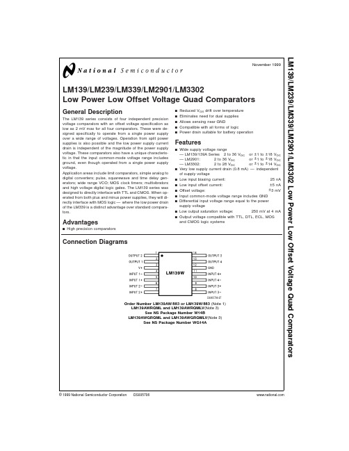
LM139/LM239/LM339/LM2901/LM3302Low Power Low Offset Voltage Quad ComparatorsGeneral DescriptionThe LM139series consists of four independent precision voltage comparators with an offset voltage specification as low as 2mV max for all four comparators.These were de-signed specifically to operate from a single power supply over a wide range of voltages.Operation from split power supplies is also possible and the low power supply current drain is independent of the magnitude of the power supply voltage.These comparators also have a unique characteris-tic in that the input common-mode voltage range includes ground,even though operated from a single power supply voltage.Application areas include limit comparators,simple analog to digital converters;pulse,squarewave and time delay gen-erators;wide range VCO;MOS clock timers;multivibrators and high voltage digital logic gates.The LM139series was designed to directly interface with TTL and CMOS.When op-erated from both plus and minus power supplies,they will di-rectly interface with MOS logic —where the low power drain of the LM339is a distinct advantage over standard compara-tors.Advantagesn High precision comparatorsn Reduced V OS drift over temperature n Eliminates need for dual supplies n Allows sensing near GNDn Compatible with all forms of logicnPower drain suitable for battery operationFeaturesn Wide supply voltage range—LM139/139A Series 2to 36V DC or ±1to ±18V DC —LM2901:2to 36V DC or ±1to ±18V DC —LM3302:2to 28V DC or ±1to ±14V DC n Very low supply current drain (0.8mA)—independent of supply voltagen Low input biasing current:25nAn Low input offset current:±5nA n Offset voltage:±3mV n Input common-mode voltage range includes GND n Differential input voltage range equal to the power supply voltagen Low output saturation voltage:250mV at 4mA n Output voltage compatible with TTL,DTL,ECL,MOS and CMOS logic systemsConnection DiagramsDS005706-27Order Number LM139AW/883or LM139W/883(Note 1)LM139AWRQML and LM139AWRQMLV (Note 3)See NS Package Number W14BLM139AWGRQML and LM139AWGRQMLV (Note 3)See NS Package Number WG14ANovember 1999LM139/LM239/LM339/LM2901/LM3302Low Power Low Offset Voltage Quad Comparators©1999National Semiconductor Corporation Connection Diagrams(Continued)Note 1:Available per JM38510/11201Note 2:Available per SMD #5962-8873901Note 3:See STD Mil Dwg 5962R96738for Radiation Tolerant DeviceDual-In-Line PackageDS005706-2Order Number LM139J,LM139J/883(Note 1),LM139AJ,LM139AJ/883(Note 2),LM239J,LM239AJ,LM339J,LM139AJRQML and LM139AJRQMLV (Note 3)See NS Package Number J14AOrder Number LM339AM,LM339M or LM2901MSee NS Package Number M14AOrder Number LM339N,LM339AN,LM2901N or LM3302NSee NS Package Number N14AL M 139/L M 239/L M 339/L M 2901/L M 3302 2LM139/LM239/LM339/LM2901/LM3302 Absolute Maximum Ratings(Note13)If Military/Aerospace specified devices are required,please contact the National Semiconductor Sales Office/ Distributors for availability and specifications.LM139/LM239/LM339LM139A/LM239A/LM339A LM3302LM2901Supply Voltage,V+36V DC or±18V DC28V DC or±14V DC Differential Input Voltage(Note11)36V DC28V DCInput Voltage−0.3V DC to+36V DC−0.3V DC to+28V DCInput Current(V IN<−0.3V DC),(Note6)50mA50mAPower Dissipation(Note4)Molded DIP1050mW1050mWCavity DIP1190mWSmall Outline Package760mWOutput Short-Circuit to GND,(Note5)Continuous ContinuousStorage Temperature Range−65˚C to+150˚C−65˚C to+150˚CLead Temperature(Soldering,10seconds)260˚C260˚COperating Temperature Range−40˚C to+85˚CLM339/LM339A0˚C to+70˚CLM239/LM239A−25˚C to+85˚CLM2901−40˚C to+85˚CLM139/LM139A−55˚C to+125˚CSoldering InformationDual-In-Line PackageSoldering(10seconds)260˚C260˚CSmall Outline PackageVapor Phase(60seconds)215˚C215˚CInfrared(15seconds)220˚C220˚CSee AN-450“Surface Mounting Methods and Their Effect on Product Reliability”for other methods of soldering surface mount devices.ESD rating(1.5kΩin series with100pF)600V600VElectrical Characteristics(V+=5V DC,T A=25˚C,unless otherwise stated)Parameter Conditions LM139A LM239A,LM339A LM139UnitsMin Typ Max Min Typ Max Min Typ MaxInput Offset Voltage(Note12) 1.0 2.0 1.0 2.0 2.0 5.0mV DCInput Bias Current I IN(+)or I IN(−)with Output in251002525025100nA DCLinear Range,(Note8),V CM=0VInput Offset Current I IN(+)−I IN(−),V CM=0V 3.025 5.050 3.025nA DCInput Common-Mode V+=30V DC(LM3302,0V+−1.50V+−1.50V+−1.5V DCVoltage Range V+=28V DC)(Note9)Supply Current R L=∞on all Comparators,0.8 2.00.8 2.00.8 2.0mA DC R L=∞,V+=36V, 1.0 2.5 1.0 2.5mA DC(LM3302,V+=28V DC)Voltage Gain R L≥15kΩ,V+=15V DC502005020050200V/mV V o=1V DC to11V DCLarge Signal V IN=TTL Logic Swing,V REF=300300300nsResponse Time 1.4V DC,V RL=5V DC,R L=5.1kΩResponse Time V RL=5V DC,R L=5.1kΩ, 1.3 1.3 1.3µs(Note10)3Electrical Characteristics(Continued)(V +=5V DC ,T A =25˚C,unless otherwise stated)ParameterConditionsLM139A LM239A,LM339A LM139UnitsMin TypMaxMin Typ MaxMin TypMaxOutput Sink Current V IN(−)=1V DC ,V IN(+)=0, 6.016 6.016 6.016mA DC V O ≤1.5V DCSaturation Voltage V IN(−)=1V DC ,V IN(+)=0,250400250400250400mV DC I SINK ≤4mAOutput Leakage V IN(+)=1V DC ,V IN(−)=0,0.10.10.1nA DC CurrentV O =5V DCElectrical Characteristics(V +=5V DC ,T A =25˚C,unless otherwise stated)ParameterConditions LM239,LM339LM2901LM3302Units MinTyp Max Min TypMax Min TypMax Input Offset Voltage (Note 12)2.0 5.0 2.07.0320mV DC Input Bias Current I IN(+)or I IN(−)with Output in 252502525025500nA DC Linear Range,(Note 8),V CM =0V Input Offset Current I IN(+)−I IN(−),V CM =0V 5.0505503100nA DC Input Common-Mode V+=30V DC (LM3302,0V +−1.50V +−1.50V +−1.5V DC Voltage Range V+=28V DC )(Note 9)Supply CurrentR L =∞on all Comparators,0.8 2.00.8 2.00.8 2.0mA DC R L =∞,V +=36V, 1.02.51.02.51.02.5mA DC (LM3302,V+=28V DC )Voltage Gain R L ≥15k Ω,V +=15V DC 5020025100230V/mV V o =1V DC to 11V DCLarge Signal V IN =TTL Logic Swing,V REF =300300300nsResponse Time 1.4V DC ,V RL =5V DC ,R L =5.1k Ω,Response Time V RL =5V DC ,R L =5.1k Ω, 1.31.3 1.3µs (Note 10)Output Sink Current V IN(−)=1V DC ,V IN(+)=0, 6.016 6.016 6.016mA DC V O ≤1.5V DCSaturation Voltage V IN(−)=1V DC ,V IN(+)=0,250400250400250500mV DC I SINK ≤4mAOutput Leakage V IN(+)=1V DC ,V IN(−)=0,0.10.10.1nA DCCurrentV O =5V DCElectrical Characteristics(V +=5.0V DC ,(Note 7))ParameterConditionsLM139A LM239A,LM339A LM139UnitsMin TypMax Min TypMax Min TypMax Input Offset Voltage (Note 12)4.0 4.09.0mV DC Input Offset Current I IN(+)−I IN(−),V CM =0V100150100nA DC Input Bias Current I IN(+)or I IN(−)with Output in300400300nA DC Linear Range,V CM =0V (Note 8)Input Common-Mode V +=30V DC (LM3302,0V +−2.00V +−2.00V +−2.0V DC Voltage Range V +=28V DC )(Note 9)Saturation VoltageV IN(−)=1V DC ,V IN(+)=0,700700700mV DCI SINK ≤4mAL M 139/L M 239/L M 339/L M 2901/L M 33024Electrical Characteristics(Continued) (V+=5.0V DC,(Note7))Parameter ConditionsLM139A LM239A,LM339ALM139Units Min Typ Max Min Typ Max Min Typ MaxOutput Leakage Current V IN(+)=1V DC,V IN(−)=0, 1.0 1.0 1.0µA DCV O=30V DC,(LM3302,V O=28V DC)Differential Input Voltage Keep all V IN’s≥0V DC(or V−,363636V DCif used),(Note11)Electrical Characteristics(V+=5.0V DC,(Note7))Parameter Conditions LM239,LM339LM2901LM3302UnitsMin Typ Max Min Typ Max Min Typ MaxInput Offset Voltage(Note12)9.091540mV DCInput Offset Current I IN(+)−I IN(−),V CM=0V150********nA DCInput Bias Current I IN(+)or I IN(−)with Output in4002005001000nA DC Linear Range,V CM=0V(Note8)Input Common-Mode V+=30V DC(LM3302,V+=28V DC)V+−2.00V+−2.00V+−2.0V DC Voltage Range(Note9)Saturation Voltage V IN(−)=1V DC,V IN(+)=0,700400700700mV DCI SINK≤4mAOutput Leakage Current V IN(+)=1V DC,V IN(−)=0, 1.0 1.0 1.0µA DC V O=30V DC,(LM3302,V O=28V DC)Differential Input Voltage Keep all V IN’s≥0V DC(or V−,363628V DC if used),(Note11)Note4:For operating at high temperatures,the LM339/LM339A,LM2901,LM3302must be derated based on a125˚C maximum junction temperature and a thermal resistance of95˚C/W which applies for the device soldered in a printed circuit board,operating in a still air ambient.The LM239and LM139must be derated basedon a150˚C maximum junction temperature.The low bias dissipation and the“ON-OFF”characteristic of the outputs keeps the chip dissipation very small(P D≤100 mW),provided the output transistors are allowed to saturate.Note5:Short circuits from the output to V+can cause excessive heating and eventual destruction.When considering short circuits to ground,the maximum output current is approximately20mA independent of the magnitude of V+.Note6:This input current will only exist when the voltage at any of the input leads is driven negative.It is due to the collector-base junction of the input PNP tran-sistors becoming forward biased and thereby acting as input diode clamps.In addition to this diode action,there is also lateral NPN parasitic transistor action on the IC chip.This transistor action can cause the output voltages of the comparators to go to the V+voltage level(or to ground for a large overdrive)for the time duration that an input is driven negative.This is not destructive and normal output states will re-establish when the input voltage,which was negative,again returns to a value greater than−0.3V DC(at25˚)C.Note7:These specifications are limited to−55˚C≤T A≤+125˚C,for the LM139/LM139A.With the LM239/LM239A,all temperature specifications are limited to−25˚C≤T A≤+85˚C,the LM339/LM339A temperature specifications are limited to0˚C≤T A≤+70˚C,and the LM2901,LM3302temperature range is−40˚C≤T A≤+85˚C.Note8:The direction of the input current is out of the IC due to the PNP input stage.This current is essentially constant,independent of the state of the output so no loading change exists on the reference or input lines.Note9:The input common-mode voltage or either input signal voltage should not be allowed to go negative by more than0.3V.The upper end of the common-mode voltage range is V+−1.5V at25˚C,but either or both inputs can go to+30V DC without damage(25V for LM3302),independent of the magnitude of V+.Note10:The response time specified is a100mV input step with5mV overdrive.For larger overdrive signals300ns can be obtained,see typical performance char-acteristics section.Note11:Positive excursions of input voltage may exceed the power supply level.As long as the other voltage remains within the common-mode range,the com-parator will provide a proper output state.The low input voltage state must not be less than−0.3V DC(or0.3V DC below the magnitude of the negative power supply, if used)(at25˚C).Note12:At output switch point,V O≅1.4V DC,R S=0Ωwith V+from5V DC to30V DC;and over the full input common-mode range(0V DC to V+−1.5V DC),at25˚C.For LM3302,V+from5V DC to28V DC.Note13:Refer to RETS139AX for LM139A military specifications and to RETS139X for LM139military specifications.LM139/LM239/LM339/LM2901/LM33025Typical Performance CharacteristicsLM139/LM239/LM339,LM139A/LM239A/LM339A,LM3302Typical Performance CharacteristicsLM2901Supply CurrentDS005706-34Input CurrentDS005706-35Output Saturation VoltageDS005706-36Response Time for Various Input Overdrives —Negative TransitionDS005706-37Response Time for Various Input Overdrives —Positive TransitionDS005706-38Supply CurrentDS005706-39Input CurrentDS005706-40Output Saturation VoltageDS005706-41L M 139/L M 239/L M 339/L M 2901/L M 3302 6Typical Performance CharacteristicsLM2901(Continued)Application HintsThe LM139series are high gain,wide bandwidth devices which,like most comparators,can easily oscillate if the out-put lead is inadvertently allowed to capacitively couple to the inputs via stray capacitance.This shows up only during the output voltage transition intervals as the comparator changes states.Power supply bypassing is not required to solve this problem.Standard PC board layout is helpful as it reduces stray input-output coupling.Reducing this input re-sistors to <10k Ωreduces the feedback signal levels and fi-nally,adding even a small amount (1to 10mV)of positive feedback (hysteresis)causes such a rapid transition that os-cillations due to stray feedback are not possible.Simply socketing the IC and attaching resistors to the pins will cause input-output oscillations during the small transition intervals unless hysteresis is used.If the input signal is a pulse wave-form,with relatively fast rise and fall times,hysteresis is not required.All pins of any unused comparators should be tied to the negative supply.The bias network of the LM139series establishes a drain current which is independent of the magnitude of the power supply voltage over the range of from 2V DC to 30V DC .It is usually unnecessary to use a bypass capacitor across the power supply line.The differential input voltage may be larger than V +without damaging the device.Protection should be provided to pre-vent the input voltages from going negative more than −0.3V DC (at 25˚C).An input clamp diode can be used as shown in the applications section.The output of the LM139series is the uncommitted collector of a grounded-emitter NPN output transistor.Many collectors can be tied together to provide an output OR’ing function.An output pull-up resistor can be connected to any available power supply voltage within the permitted supply voltage range and there is no restriction on this voltage due to the magnitude of the voltage which is applied to the V +terminal of the LM139A package.The output can also be used as a simple SPST switch to ground (when a pull-up resistor is not used).The amount of current which the output device can sink is limited by the drive available (which is independent of V +)and the βof this device.When the maximum current limit is reached (approximately 16mA),the output transistor will come out of saturation and the output voltage will rise very rapidly.The output saturation voltage is limited by the ap-proximately 60ΩR SAT of the output transistor.The low offset voltage of the output transistor (1mV)allows the output to clamp essentially to ground level for small load currents.Typical Applications(V +=5.0V DC )Response Time for Various Input Overdrives —Negative TransitionDS005706-42Response Time for Various Input Overdrives-Positive TransitionDS005706-43Basic ComparatorDS005706-3Driving CMOSDS005706-4Driving TTLDS005706-5LM139/LM239/LM339/LM2901/LM33027Typical Applications(V +=5.0V DC )(Continued)Typical Applications(V +=15V DC )AND GateDS005706-8OR GateDS005706-9One-Shot Multivibrator 8LM139/LM239/LM339/LM2901/LM3302Typical Applications(V+=15V)(Continued)DCOne-Shot Multivibrator with Input Lock Out Array DS005706-129Typical Applications(V +=15V DC )(Continued)Large Fan-In AND GateDS005706-13ORing the OutputsDS005706-15L M 139/L M 239/L M 339/L M 2901/L M 3302 10LM139/LM239/LM339/LM2901/LM3302Typical Applications(V+=15V)(Continued)DCPulse Generator Array DS005706-1711Typical Applications(V +=15V DC )(Continued)Time Delay GeneratorDS005706-14Non-Inverting Comparator with Hysteresis DS005706-18Inverting Comparator with HysteresisDS005706-19L M 139/L M 239/L M 339/L M 2901/L M 3302 12Typical Applications(V +=15V DC )(Continued)Squarewave OscillatorDS005706-16Basic ComparatorDS005706-24Comparing Input Voltages of Opposite PolarityDS005706-20LM139/LM239/LM339/LM2901/LM330213Typical Applications(V +=15V DC )(Continued)Output StrobingDS005706-22*Or open-collector logic gate without pull-up resistorCrystal Controlled OscillatorDS005706-25L M 139/L M 239/L M 339/L M 2901/L M 3302 14Typical Applications(V +=15V DC )(Continued)T w o -D e c a d e H i g h -F r e q u e n c y V C OD S 005706-23V +=+30V D C250m V D C ≤V C ≤+50V D C700H z ≤f o ≤100k H zLM139/LM239/LM339/LM2901/LM330215Typical Applications(V +=15V DC )(Continued)Split-Supply Applications(V +=+15V DC and V −=−15V DC )Transducer AmplifierDS005706-28Zero Crossing Detector (Single Power Supply)DS005706-30MOS Clock DriverDS005706-31L M 139/L M 239/L M 339/L M 2901/L M 3302 16Split-Supply Applications(V +=+15V DC and V −=−15V DC )(Continued)Schematic DiagramZero Crossing DetectorDS005706-32Comparator With a NegativeReferenceDS005706-33DS005706-1LM139/LM239/LM339/LM2901/LM330217Physical Dimensionsinches (millimeters)unless otherwise notedCeramic Dual-In-Line Package (J)Order Number LM139J,LM139J/883,LM139AJ,LM139AJ/883,LM239J,LM239AJ,LM339JNS Package Number J14AS.O.Package (M)Order Number LM339AM,LM339M or LM2901MNS Package Number M14AL M 139/L M 239/L M 339/L M 2901/L M 3302 18Physical Dimensionsinches (millimeters)unless otherwise noted (Continued)Molded Dual-In-Line Package (N)Order Number LM339N,LM339AN,LM2901N or LM3302NNS Package Number N14AOrder Number LM139AW/883or LM139W/883NS Package Number W14BLM139/LM239/LM339/LM2901/LM330219NotesLIFE SUPPORT POLICYNATIONAL’S PRODUCTS ARE NOT AUTHORIZED FOR USE AS CRITICAL COMPONENTS IN LIFE SUPPORT DEVICES OR SYSTEMS WITHOUT THE EXPRESS WRITTEN APPROVAL OF THE PRESIDENT AND GENERAL COUNSEL OF NATIONAL SEMICONDUCTOR CORPORATION.As used herein:1.Life support devices or systems are devices or systems which,(a)are intended for surgical implant into the body,or (b)support or sustain life,and whose failure to perform when properly used in accordance with instructions for use provided in the labeling,can be reasonably expected to result in a significant injury to the user.2.A critical component is any component of a life support device or system whose failure to perform can be reasonably expected to cause the failure of the life support device or system,or to affect its safety or effectiveness.National Semiconductor Corporation AmericasTel:1-800-272-9959Fax:1-800-737-7018Email:support@National Semiconductor EuropeFax:+49(0)180-5308586Email:europe.support@Deutsch Tel:+49(0)180-5308585English Tel:+49(0)180-5327832Français Tel:+49(0)180-5329358Italiano Tel:+49(0)180-5341680National Semiconductor Asia Pacific Customer Response Group Tel:65-2544466Fax:65-2504466Email:sea.support@National Semiconductor Japan Ltd.Tel:81-3-5639-7560Fax:81-3-5639-7507L M 139/L M 239/L M 339/L M 2901/L M 3302L o w P o w e r L o w O f f s e t V o l t a g e Q u a d C o m p a r a t o r sNational does not assume any responsibility for use of any circuitry described,no circuit patent licenses are implied and National reserves the right at any time without notice to change said circuitry and specifications.。

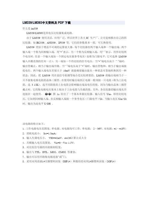
lm339应用电路图集lm339应用电路图:LM339集成块内部装有四个独立的电压比较器,该电压比较器的特点是:失调电压小,典型值为2mV;电源电压范围宽,单电源为2-36V,双电源电压为±1V-±18V;对比较信号源的内阻限制较宽;共模范围很大,为0~(Ucc-1.5 V)Vo;差动输入电压范围较大,大到可以等于电源电压;输出端电位可灵活方便地选用。
LM339集成块采用C-14型封装,图1为外型及管脚排列图。
由于LM339使用灵活,应用广泛,所以世界上各大IC生产厂、公司竟相推出自己的四比较器,如IR2339、ANI339、SF339等,它们的参数基本一致,可互换使用。
LM339类似于增益不可调的运算放大器。
每个比较器有两个输入端和一个输出端。
两个输入端一个称为同相输入端,用“+”表示,另一个称为反相输入端,用“-”表示。
用作比较两个电压时,任意一个输入端加一个固定电压做参考电压(也称为门限电平,它可选择LM 339输入共模范围的任何一点),另一端加一个待比较的信号电压。
当“+”端电压高于“-”端时,输出管截止,相当于输出端开路。
当“-”端电压高于“+”端时,输出管饱和,相当于输出端接低电位。
两个输入端电压差别大于10mV就能确保输出能从一种状态可靠地转换到另一种状态,因此,把LM339用在弱信号检测等场合是比较理想的。
LM339的输出端相当于一只不接集电极电阻的晶体三极管,在使用时输出端到正电源一般须接一只电阻(称为上拉电阻,选3-15K)。
选不同阻值的上拉电阻会影响输出端高电位的值。
因为当输出晶体三极管截止时,它的集电极电压基本上取决于上拉电阻与负载的值。
另外,各比较器的输出端允许连接在一起使用。
单限比较器电路图3为某仪器中过热检测保护电路。
它用单电源供电,1/4LM339的反相输入端加一个固定的参考电压,它的值取决于R1于R2。
UR=R2/(R1+R2)*UCC。
同相端的电压就等于热敏元件Rt的电压降。

lm339技术参数LM339是一种四路比较器,具有高速、低功耗和稳定性好等特点,被广泛应用于模拟信号处理、电压检测和开关控制等领域。
下面将从工作电压、输入电压范围、输出电流和响应时间等方面介绍LM339的技术参数。
首先是工作电压。
LM339的工作电压范围为2V至36V,可以在广泛的电源电压下正常工作。
这使得LM339可以适用于各种不同的电源设计和应用场景。
同时,LM339的低工作电流也使得它可以在低功耗的系统中使用。
其次是输入电压范围。
LM339的输入电压范围是从负电源电压到正电源电压,这使得LM339可以在双电源系统中灵活应用。
此外,LM339还具有高共模抑制比和低输入偏置电流,能够准确地检测和比较输入信号。
再次是输出电流。
LM339的输出电流能力较强,可以提供高达16mA的输出电流。
这意味着LM339可以驱动一定的负载电流,满足各种应用的需求。
最后是响应时间。
LM339的响应时间非常短,通常在1us以下。
这使得它能够快速响应输入信号的变化,并在短时间内输出准确的比较结果。
这对于需要高速响应的应用场景非常重要。
除了以上几个重要的技术参数外,LM339还具有其他一些特点。
例如,它具有内部电压参考源,可以简化电路设计和调整阈值电平。
此外,LM339还具有较高的输入阻抗和低的输出阻抗,能够有效地减少信号失真和干扰。
在实际应用中,LM339可以用于电压比较、开关控制、电压检测和信号处理等方面。
例如,在电源管理中,可以使用LM339来实现电池电压的监测和低电压保护;在电机控制中,可以使用LM339来检测电机的转速和方向;在传感器信号处理中,可以使用LM339来比较和处理传感器输出的模拟信号。
总结起来,LM339作为一种四路比较器,具有工作电压范围广、输入电压范围大、输出电流能力强和响应时间短等特点。
它的优良性能使得它在各种应用中得到了广泛的应用。
无论是在电源管理、电机控制还是传感器信号处理等领域,LM339都可以发挥重要的作用。
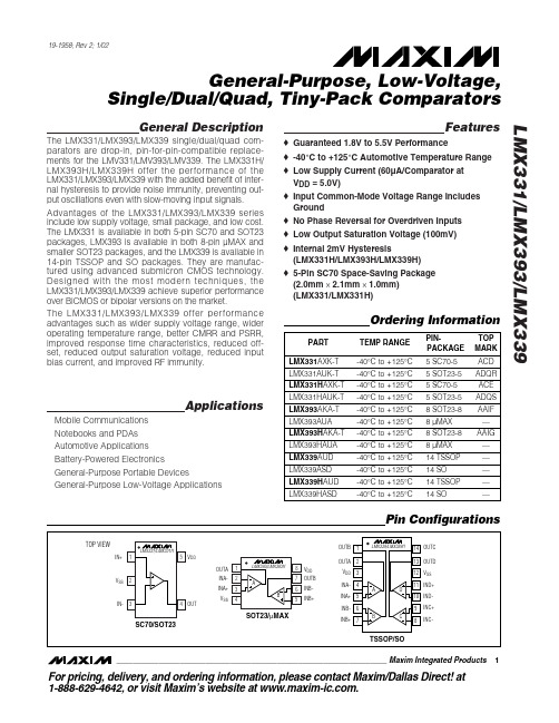
General DescriptionThe LMX331/LMX393/LMX339 single/dual/quad com-parators are drop-in, pin-for-pin-compatible replace-ments for the LMV331/LMV393/LMV339. The LMX331H/LMX393H/LMX339H offer the performance of the LMX331/LMX393/LMX339 with the added benefit of inter-nal hysteresis to provide noise immunity, preventing out-put oscillations even with slow-moving input signals.Advantages of the LMX331/LMX393/LMX339 series include low supply voltage, small package, and low cost.The LMX331 is available in both 5-pin SC70 and SOT23packages, LMX393 is available in both 8-pin µMAX and smaller SOT23 packages, and the LMX339 is available in 14-pin TSSOP and SO packages. They are manufac-tured using advanced submicron CMOS technology.Designed with the most modern techniques, the LMX331/LMX393/LMX339 achieve superior performance over BiCMOS or bipolar versions on the market.The LMX331/LMX393/LMX339 offer performance advantages such as wider supply voltage range, wider operating temperature range, better CMRR and PSRR,improved response time characteristics, reduced off-set, reduced output saturation voltage, reduced input bias current, and improved RF immunity.ApplicationsMobile Communications Notebooks and PDAs Automotive Applications Battery-Powered ElectronicsGeneral-Purpose Portable DevicesGeneral-Purpose Low-Voltage ApplicationsFeatureso Guaranteed 1.8V to 5.5V Performanceo -40°C to +125°C Automotive Temperature Range o Low Supply Current (60µA/Comparator at V DD = 5.0V)o Input Common-Mode Voltage Range Includes Groundo No Phase Reversal for Overdriven Inputs o Low Output Saturation Voltage (100mV)o Internal 2mV Hysteresis(LMX331H/LMX393H/LMX339H)o 5-Pin SC70 Space-Saving Package (2.0mm ✕2.1mm ✕1.0mm)(LMX331/LMX331H)LMX331/LMX393/LMX339General-Purpose, Low-Voltage,Single/Dual/Quad, Tiny-Pack Comparators________________________________________________________________Maxim Integrated Products 1Pin Configurations19-1958; Rev 2; 1/02For pricing, delivery, and ordering information,please contact Maxim/Dallas Direct!at1-888-629-4642, or visit Maxim’s website at .Ordering InformationL M X 331/L M X 393/L M X 339General-Purpose, Low-Voltage,Single/Dual/Quad, Tiny-Pack ComparatorsABSOLUTE MAXIMUM RATINGSDC ELECTRICAL CHARACTERISTICS —2.7V OPERATIONStresses beyond those listed under “Absolute Maximum Ratings” may cause permanent damage to the device. These are stress ratings only, and functional operation of the device at these or any other conditions beyond those indicated in the operational sections of the specifications is not implied. Exposure to absolute maximum rating conditions for extended periods may affect device reliability.Supply Voltage (V DD to V SS )...................................-0.3V to +6V All Other Pins..................................(V SS - 0.3V) to (V DD + 0.3V)Continuous Power Dissipation (T A = +70°C)5-Pin SC70 (derate 3.1mW/°C above +70°C)..............247mW 5-Pin SOT23 (derate 7.1mW/°C above +70°C)............571mW 8-Pin SOT23 (derate 8.9mW/°C above +70°C)............714mW 8-Pin µMAX (derate 10.3mW/°C above +70°C)...........825mW14-Pin TSSOP (derate 9.1mW/°C above +70°C).........727mW 14-Pin SO (derate 8.3mW/°C above +70°C).............666.7mW Operating Temperature Range .........................-40°C to +125°C Junction Temperature......................................................+150°C Storage Temperature Range.............................-65°C to +150°C Lead Temperature (soldering, 10s).................................+300°CAC ELECTRICAL CHARACTERISTICS —2.7V OPERATION(V DD = 2.7V, V SS = 0, V CM = 0, R L = 5.1k Ωconnected to V DD . Typical values are at T A = +25°C.) (Note 1)LMX331/LMX393/LMX339General-Purpose, Low-Voltage,Single/Dual/Quad, Tiny-Pack ComparatorsDC ELECTRICAL CHARACTERISTICS —5.0V OPERATION(V = 5V, V = 0, V = 0, R = 5.1k Ωconnected to V . Typical values are at T = +25°C.) (Note 1)AC ELECTRICAL CHARACTERISTICS —5.0V OPERATION(V DD = 5V, V SS = 0, V CM = 0, R L = 5.1k Ωconnected to V DD . Typical values are at T A = +25°C.) (Note 1)L M X 331/L M X 393/L M X 339General-Purpose, Low-Voltage,Single/Dual/Quad, Tiny-Pack Comparators 4_______________________________________________________________________________________DC ELECTRICAL CHARACTERISTICS —1.8V OPERATION(V DD = 1.8V, V SS = 0, V CM = 0, R L = 5.1k Ωconnected to V DD . Typical values are at T A = +25°C.)Note 2:Supply current when output is high.Note 3:Input overdrive is the overdrive voltage beyond the offset and hysteresis-determined trip points.AC ELECTRICAL CHARACTERISTICS —1.8V OPERATION(V DD = 1.8V, V SS = 0, V CM = 0, R L = 5.1k Ωconnected to V DD . Typical values are at T A = +25°C.)LMX331/LMX393/LMX339General-Purpose, Low-Voltage,Single/Dual/Quad, Tiny-Pack Comparators_______________________________________________________________________________________50302010405060708090100132456LMX331SUPPLY CURRENT vs. SUPPLY VOLTAGESUPPLY VOLTAGE (V)S U P P L Y C U R R E N T (µA )40201008060160140120180132456LMX331SUPPLY CURRENT vs. SUPPLY VOLTAGESUPPLY VOLTAGE (V)S U P P L Y C U R R E N T (µA )-1.0-0.50.51.01.5-4020-20406080100120INPUT OFFSET VOLTAGE vs. TEMPERATURETEMPERATURE (°C)I N P U T O F F S E T V O L T A G E (m V )040208060120100140OUTPUT LOW VOLTAGE vs. SINK CURRENTSINK CURRENT (mA)O U T P U T L O W V O L T A G E (m V )123460708090100110120-400-2020406080100120OUTPUT LOW VOLTAGE vs. TEMPERATURETEMPERATURE (°C)O U T P U T L O W V O L TA G E (m V )0200100400300500600040602080100120PROPAGATION DELAY vs. CAPACITIVE LOADCAPACITIVE LOAD (pF)P R O P A G A T I O N D E L A Y (n s )0257550125150100175-4020-20406080100120PROPAGATION DELAY vs. TEMPERATURETEMPERATURE (°C)P R O P A G A T I O N D E L A Y (n s )015010050200250300350400450500502575100125150PROPAGATION DELAY vs. INPUT OVERDRIVE (t PLH )INPUT OVERDRIVE (mV)P R O P A G A T I O N D E L A Y (n s )060402080100120140160180200502575100125150PROPAGATION DELAY vs. INPUT OVERDRIVE (t PHL )INPUT OVERDRIVE (mV)P R O P A G A T I O N D E L A Y (n s )Typical Operating Characteristics(V DD = 5V, V SS = 0, V CM = 0, R L = 5.1k Ω, C L = 10pF, overdrive = 100mV, T A = +25°C, unless otherwise noted.)L M X 331/L M X 393/L M X 339General-Purpose, Low-Voltage,Single/Dual/Quad, Tiny-Pack Comparators 6_______________________________________________________________________________________Typical Operating Characteristics (continued)(V DD = 5V, V SS = 0, V CM = 0, R L = 5.1k Ω, C L = 10pF, overdrive = 100mV, T A = +25°C, unless otherwise noted.)00.51.01.52.02.53.0-40-2020406080100120LMX331H/LMX393H/LMX339H HYSTERESIS vs. TEMPERATUREL M X 331 t o c 10TEMPERATURE (°C)H Y S T E R E S I S (m V )13245132456LMX331H/LMX393H/LMX339H HYSTERESIS vs. SUPPLY VOLTAGESUPPLY VOLTAGE (V)H Y S T E R E S I S (m V )TIME (200ns/div)(IN-) - IN+100mV/divOUT 2V/divL M X 331 t o c 12PROPAGATION DELAY 100mV OVERDRIVETIME (200ns/div)(IN-) - IN+10mV/div OUT 2V/divL M X 331 t o c 13PROPAGATION DELAY 10mV OVERDRIVETIME (500ns/div)(IN-) - IN+100mV/divOUT 2V/divL M X 331 t o c 14500kHz RESPONSE 100mV OVERDRIVETIME (500ns/div)(IN-) - IN+10mV/divOUT 2V/divL M X 331 t o c 15500kHz RESPONSE 10mV OVERDRIVETIME (2µs/div)(IN-) - IN+100mV/div OUT 2V/divL M X 331 t o c 16100kHz RESPONSE 100mV OVERDRIVETIME (2µs/div)(IN-) - IN+10mV/divOUT 2V/divL M X 331 t o c 17100kHz RESPONSE 10mV OVERDRIVETIME (1µs/div)V DD 2V/divOUT 2V/divL M X 331 t o c 18POWER-UP RESPONSELMX331/LMX393/LMX339General-Purpose, Low-Voltage,Single/Dual/Quad, Tiny-Pack Comparators_______________________________________________________________________________________7Detailed DescriptionThe LMX331/LMX393/LMX339 are single/dual/quad,low-cost, general-purpose comparators. They have a single-supply operating voltage of 1.8V to 5V. The com-mon-mode input range extends from -0.1V below the negative supply to within 0.7V of the positive supply.They require approximately 60µA per comparator with a 5V supply and 40µA with a 2.7V supply.The LMX331H/LMX393H/LMX339H have 2mV of hys-teresis for noise immunity. This significantly reduces the chance of output oscillations even with slow-moving input signals. The LMX331/LMX393/LMX339 and LMX331H/LMX393H/LMX339H are ideal for automotive applications because they operate from -40°C to +125°C (see Typical Operating Characteristics ).Applications InformationHysteresisMany comparators oscillate in the linear region of oper-ation because of noise or undesired parasitic feed-back. This tends to occur when the voltage on one input is equal or very close to the voltage on the other input. The LMX331H/LMX393H/LMX339H have internal hysteresis to counter parasitic effects and noise.The hysteresis in a comparator creates two trip points:one for the rising input voltage and one for the fallinginput voltage (Figure 1). The difference between the trip points is the hysteresis. When the comparator's input voltages are equal, the hysteresis effectively causes one comparator input to move quickly past the other,thus taking the input out of the region where oscillation occurs. This provides clean output transitions for noisy,slow-moving input signals.Additional hysteresis can be generated with two resis-tors, using positive feedback (Figure 2). Use the follow-ing procedure to calculate resistor values:Figure 1. Threshold Hysteresis Band (Not to Scale)L M X 331/L M X 393/L M X 339General-Purpose, Low-Voltage,Single/Dual/Quad, Tiny-Pack Comparators 8_______________________________________________________________________________________1)Find output voltage when output is high:V OUT(HIGH)= V DD - I LOAD ✕R L2)Find the trip points of the comparator using theseformulas:V TH = V REF + ((V OUT(HIGH)- V REF )R2) / (R1 + R2)V TL = V REF (1 - (R2 / (R1 + R2)))where V TH is the threshold voltage at which the com-parator switches its output from high to low as V IN rises above the trip point, and V TL is the threshold voltage at which the comparator switches its output from low to high as V IN drops below the trip point.3)The hysteresis band will be:V HYST = V TH - V TL = V DD (R2 / (R1 + R2))In this example, let V DD = 5V, V REF = 2.5V, I LOAD =50nA, R L = 5.1k Ω:V OUT(HIGH)= 5.0V - (50 ✕10-9✕5.1 ✕103Ω) ≈5.0VV TH = 2.5V + 2.5V(R2 / (R1 + R2))V TL = 2.5V(1 - (R2 / (R1 + R2)))Select R2. In this example, we will choose 1k Ω.Select V HYST . In this example, we will choose 50mV.Solve for R1:V HYST = V OUT(HIGH)(R2 / (R1 + R2)) V0.050V = 5(1000 / (R1 + 1000)) Vwhere R1 ≈100k Ω, V TH = 2.525V, and V TL = 2.475V.Choose R1 and R2 to be large enough as not to exceed the amount of current the reference can supply.The source current required is V REF / (R1 + R2).The sink current is (V OUT(HIGH)- V REF ) ✕(R1 + R2).Choose R L to be large enough to avoid drawing excess current, yet small enough to supply the necessary cur-rent to drive the load. R L should be between 1k Ωand 10k Ω.Board Layout and BypassingUse 0.1µF bypass capacitors from V DD to V SS . To max-imize performance, minimize stray inductance by putting this capacitor close to the V DD pin and reduc-ing trace lengths. For slow-moving input signals (rise time > 1ms), use a 1nF capacitor between IN+ and IN-to reduce high-frequency noise.Chip InformationLMX331/LMX331H TRANSISTOR COUNT: 112LMX393/LMX393H TRANSISTOR COUNT: 211LMX339/LMX339H TRANSISTOR COUNT: 411Figure 2. Adding Hysteresis with External ResistorsLMX331/LMX393/LMX339General-Purpose, Low-Voltage,Single/Dual/Quad, Tiny-Pack ComparatorsPackage InformationL M X 331/L M X 393/L M X 339General-Purpose, Low-Voltage,Single/Dual/Quad, Tiny-Pack ComparatorsPackage Information (continued)LMX331/LMX393/LMX339General-Purpose, Low-Voltage,Single/Dual/Quad, Tiny-Pack Comparators ______________________________________________________________________________________11Package Information (continued)L M X 331/L M X 393/L M X 339General-Purpose, Low-Voltage,Single/Dual/Quad, Tiny-Pack ComparatorsMaxim cannot assume responsibility f or use of any circuitry other than circuitry entirely embodied in a Maxim product. No circuit patent licenses are implied. Maxim reserves the right to change the circuitry and specifications without notice at any time.12____________________Maxim Integrated Products, 120 San Gabriel Drive, Sunnyvale, CA 94086 408-737-7600©2002 Maxim Integrated Products Printed USAis a registered trademark of Maxim Integrated Products.Package Information (continued)。
IMPORTANT NOTICETexas Instruments Incorporated and its subsidiaries(TI)reserve the right to make corrections,modifications,enhancements, improvements,and other changes to its products and services at any time and to discontinue any product or service without notice. Customers should obtain the latest relevant information before placing orders and should verify that such information is current and complete.All products are sold subject to TI’s terms and conditions of sale supplied at the time of order acknowledgment.TI warrants performance of its hardware products to the specifications applicable at the time of sale in accordance with TI’s standard warranty.Testing and other quality control techniques are used to the extent TI deems necessary to support this warranty.Except where mandated by government requirements,testing of all parameters of each product is not necessarily performed.TI assumes no liability for applications assistance or customer product design.Customers are responsible for their products and applications using TI components.To minimize the risks associated with customer products and applications,customers should provide adequate design and operating safeguards.TI does not warrant or represent that any license,either express or implied,is granted under any TI patent right,copyright,mask work right,or other TI intellectual property right relating to any combination,machine,or process in which TI products or services are rmation published by TI regarding third-party products or services does not constitute a license from TI to use such products or services or a warranty or endorsement e of such information may require a license from a third party under the patents or other intellectual property of the third party,or a license from TI under the patents or other intellectual property of TI. Reproduction of information in TI data books or data sheets is permissible only if reproduction is without alteration and is accompanied by all associated warranties,conditions,limitations,and notices.Reproduction of this information with alteration is an unfair and deceptive business practice.TI is not responsible or liable for such altered documentation.Resale of TI products or services with statements different from or beyond the parameters stated by TI for that product or service voids all express and any implied warranties for the associated TI product or service and is an unfair and deceptive business practice.TI is not responsible or liable for any such statements.TI products are not authorized for use in safety-critical applications(such as life support)where a failure of the TI product would reasonably be expected to cause severe personal injury or death,unless officers of the parties have executed an agreement specifically governing such use.Buyers represent that they have all necessary expertise in the safety and regulatory ramifications of their applications,and acknowledge and agree that they are solely responsible for all legal,regulatory and safety-related requirements concerning their products and any use of TI products in such safety-critical applications,notwithstanding any applications-related information or support that may be provided by TI.Further,Buyers must fully indemnify TI and its representatives against any damages arising out of the use of TI products in such safety-critical applications.TI products are neither designed nor intended for use in military/aerospace applications or environments unless the TI products are specifically designated by TI as military-grade or"enhanced plastic."Only products designated by TI as military-grade meet military specifications.Buyers acknowledge and agree that any such use of TI products which TI has not designated as military-grade is solely at the Buyer's risk,and that they are solely responsible for compliance with all legal and regulatory requirements in connection with such use.TI products are neither designed nor intended for use in automotive applications or environments unless the specific TI products are designated by TI as compliant with ISO/TS16949requirements.Buyers acknowledge and agree that,if they use anynon-designated products in automotive applications,TI will not be responsible for any failure to meet such requirements. Following are URLs where you can obtain information on other Texas Instruments products and application solutions:Products ApplicationsAmplifiers Audio /audioData Converters Automotive /automotiveDSP Broadband /broadbandInterface Digital Control /digitalcontrolLogic Military /militaryPower Mgmt Optical Networking /opticalnetworkMicrocontrollers Security /securityLow Power /lpw Telephony /telephonyWirelessVideo&Imaging /videoWireless /wirelessMailing Address:Texas Instruments,Post Office Box655303,Dallas,Texas75265Copyright©2007,Texas Instruments IncorporatedPACKAGING INFORMATIONOrderableDevice Status (1)Package Type Package Drawing Pins Package Qty Eco Plan (2)Lead/Ball Finish MSL Peak Temp (3)LMV331IDBVR ACTIVE SOT-23DBV 53000Green (RoHS &no Sb/Br)CU NIPDAU Level-1-260C-UNLIM LMV331IDBVRE4ACTIVE SOT-23DBV 53000Green (RoHS &no Sb/Br)CU NIPDAU Level-1-260C-UNLIM LMV331IDBVRG4ACTIVE SOT-23DBV 53000Green (RoHS &no Sb/Br)CU NIPDAU Level-1-260C-UNLIM LMV331IDBVT ACTIVE SOT-23DBV 5250Green (RoHS &no Sb/Br)CU NIPDAU Level-1-260C-UNLIM LMV331IDBVTE4ACTIVE SOT-23DBV 5250Green (RoHS &no Sb/Br)CU NIPDAU Level-1-260C-UNLIM LMV331IDCKR ACTIVE SC70DCK 53000Green (RoHS &no Sb/Br)CU NIPDAU Level-1-260C-UNLIM LMV331IDCKRE4ACTIVE SC70DCK 53000Green (RoHS &no Sb/Br)CU NIPDAU Level-1-260C-UNLIM LMV331IDCKRG4ACTIVE SC70DCK 53000Green (RoHS &no Sb/Br)CU NIPDAU Level-1-260C-UNLIM LMV331IDCKT ACTIVE SC70DCK 5250Green (RoHS &no Sb/Br)CU NIPDAU Level-1-260C-UNLIM LMV331IDCKTE4ACTIVE SC70DCK 5250Green (RoHS &no Sb/Br)CU NIPDAU Level-1-260C-UNLIM LMV331IDCKTG4ACTIVE SC70DCK 5250TBD Call TI Call TILMV339ID ACTIVE SOIC D 1450Green (RoHS &no Sb/Br)CU NIPDAU Level-1-260C-UNLIM LMV339IDE4ACTIVE SOIC D 1450Green (RoHS &no Sb/Br)CU NIPDAU Level-1-260C-UNLIM LMV339IDG4ACTIVE SOIC D 1450Green (RoHS &no Sb/Br)CU NIPDAU Level-1-260C-UNLIM LMV339IDR ACTIVE SOIC D 142500Green (RoHS &no Sb/Br)CU NIPDAU Level-1-260C-UNLIM LMV339IDRE4ACTIVE SOIC D 142500Green (RoHS &no Sb/Br)CU NIPDAU Level-1-260C-UNLIM LMV339IDRG4ACTIVE SOIC D 142500Green (RoHS &no Sb/Br)CU NIPDAU Level-1-260C-UNLIM LMV339IPW ACTIVE TSSOP PW 1490Green (RoHS &no Sb/Br)CU NIPDAU Level-1-260C-UNLIM LMV339IPWE4ACTIVE TSSOP PW 1490Green (RoHS &no Sb/Br)CU NIPDAU Level-1-260C-UNLIM LMV339IPWR ACTIVE TSSOP PW 142000Green (RoHS &no Sb/Br)CU NIPDAU Level-1-260C-UNLIM LMV339IPWRE4ACTIVE TSSOP PW 142000Green (RoHS &no Sb/Br)CU NIPDAU Level-1-260C-UNLIM LMV393ID ACTIVE SOIC D 875Green (RoHS &no Sb/Br)CU NIPDAU Level-1-260C-UNLIM LMV393IDDUR ACTIVE VSSOP DDU 83000Green (RoHS &no Sb/Br)CU NIPDAU Level-1-260C-UNLIM LMV393IDDURE4ACTIVE VSSOP DDU 83000Green (RoHS &no Sb/Br)CU NIPDAU Level-1-260C-UNLIM LMV393IDE4ACTIVESOICD875Green (RoHS &no Sb/Br)CU NIPDAULevel-1-260C-UNLIM3-May-2007Orderable Device Status (1)Package Type Package DrawingPins Package Qty Eco Plan (2)Lead/Ball Finish MSL Peak Temp (3)LMV393IDG4ACTIVE SOIC D 875Green (RoHS &no Sb/Br)CU NIPDAU Level-1-260C-UNLIM LMV393IDGKR ACTIVE MSOP DGK 82500Green (RoHS &no Sb/Br)CU NIPDAU Level-1-260C-UNLIM LMV393IDGKRG4ACTIVE MSOP DGK 82500Green (RoHS &no Sb/Br)CU NIPDAU Level-1-260C-UNLIM LMV393IDR ACTIVE SOIC D 82500Green (RoHS &no Sb/Br)CU NIPDAU Level-1-260C-UNLIM LMV393IDRE4ACTIVE SOIC D 82500Green (RoHS &no Sb/Br)CU NIPDAU Level-1-260C-UNLIM LMV393IDRG4ACTIVE SOIC D 82500Green (RoHS &no Sb/Br)CU NIPDAU Level-1-260C-UNLIM LMV393IPW ACTIVE TSSOP PW 8150Green (RoHS &no Sb/Br)CU NIPDAU Level-1-260C-UNLIM LMV393IPWE4ACTIVE TSSOP PW 8150Green (RoHS &no Sb/Br)CU NIPDAU Level-1-260C-UNLIM LMV393IPWR ACTIVE TSSOP PW 82000Green (RoHS &no Sb/Br)CU NIPDAU Level-1-260C-UNLIM LMV393IPWRE4ACTIVE TSSOP PW 82000Green (RoHS &no Sb/Br)CU NIPDAU Level-1-260C-UNLIM LMV393IPWRG4ACTIVETSSOPPW82000Green (RoHS &no Sb/Br)CU NIPDAULevel-1-260C-UNLIM(1)The marketing status values are defined as follows:ACTIVE:Product device recommended for new designs.LIFEBUY:TI has announced that the device will be discontinued,and a lifetime-buy period is in effect.NRND:Not recommended for new designs.Device is in production to support existing customers,but TI does not recommend using this part in a new design.PREVIEW:Device has been announced but is not in production.Samples may or may not be available.OBSOLETE:TI has discontinued the production of the device.(2)Eco Plan -The planned eco-friendly classification:Pb-Free (RoHS),Pb-Free (RoHS Exempt),or Green (RoHS &no Sb/Br)-please check /productcontent for the latest availability information and additional product content details.TBD:The Pb-Free/Green conversion plan has not been defined.Pb-Free (RoHS):TI's terms "Lead-Free"or "Pb-Free"mean semiconductor products that are compatible with the current RoHS requirements for all 6substances,including the requirement that lead not exceed 0.1%by weight in homogeneous materials.Where designed to be soldered at high temperatures,TI Pb-Free products are suitable for use in specified lead-free processes.Pb-Free (RoHS Exempt):This component has a RoHS exemption for either 1)lead-based flip-chip solder bumps used between the die and package,or 2)lead-based die adhesive used between the die and leadframe.The component is otherwise considered Pb-Free (RoHS compatible)as defined above.Green (RoHS &no Sb/Br):TI defines "Green"to mean Pb-Free (RoHS compatible),and free of Bromine (Br)and Antimony (Sb)based flame retardants (Br or Sb do not exceed 0.1%by weight in homogeneous material)(3)MSL,Peak Temp.--The Moisture Sensitivity Level rating according to the JEDEC industry standard classifications,and peak solder temperature.Important Information and Disclaimer:The information provided on this page represents TI's knowledge and belief as of the date that it is provided.TI bases its knowledge and belief on information provided by third parties,and makes no representation or warranty as to the accuracy of such information.Efforts are underway to better integrate information from third parties.TI has taken and continues to take reasonable steps to provide representative and accurate information but may not have conducted destructive testing or chemical analysis on incoming materials and chemicals.TI and TI suppliers consider certain information to be proprietary,and thus CAS numbers and other limited information may not be available for release.In no event shall TI's liability arising out of such information exceed the total purchase price of the TI part(s)at issue in this document sold by TI to Customer on an annual basis.3-May-2007TAPE AND REELINFORMATION30-Apr-2007DevicePackage Pins SiteReel Diameter (mm)Reel Width (mm)A0(mm)B0(mm)K0(mm)P1(mm)W (mm)Pin1Quadrant LMV339IDR D 14MLA 33016 6.59.0 2.1816Q1LMV339IPWR PW 14MLA 330127.0 5.6 1.6812Q1LMV393IDGKR DGK 8HNT 18013 5.3 3.4 1.4812Q1LMV393IDR D 8FMX 33012 6.4 5.2 2.1812Q1LMV393IPWRPW8MLA330127.03.61.6812Q1TAPE AND REEL BOX INFORMATIONDevice PackagePins Site Length (mm)Width (mm)Height (mm)LMV339IDR D 14MLA 333.2333.228.58LMV339IPWR PW 14MLA 338.1340.520.64LMV393IDGKR DGK 8HNT 0.00.00.0LMV393IDR D 8FMX 338.1340.520.64LMV393IPWRPW8MLA338.1340.520.6430-Apr-200730-Apr-2007。
LM339/LM393中文资料及PDF下载什么是lm339LM339/LM393是四电压比较器集成电路。
由于LM339 使用灵活,应用广泛,所以世界上各大IC 生产厂、公司竟相推出自己的四比较器,如IR2339、ANI339、SF339 等,它们的参数基本一致,可互换使用。
LM339 类似于增益不可调的运算放大器。
每个比较器有两个输入端和一个输出端。
两个输入端一个称为同相输入端,用“+”表示,另一个称为反相输入端,用“-”表示。
用作比较两个电压时,任意一个输入端加一个固定电压做参考电压(也称为门限电平,它可选择LM339 输入共模范围的任何一点),另一端加一个待比较的信号电压。
当“+”端电压高于“-”端时,输出管截止,相当于输出端开路。
当“-”端电压高于“+”端时,输出管饱和,相当于输出端接低电位。
两个输入端电压差别大于10mV 就能确保输出能从一种状态可靠地转换到另一种状态,因此,把LM339 用在弱信号检测等场合是比较理想的。
LM339 的输出端相当于一只不接集电极电阻的晶体三极管,在使用时输出端到正电源一般须接一只电阻(称为上拉电阻,选3-15K)。
选不同阻值的上拉电阻会影响输出端高电位的值。
因为当输出晶体三极管截止时,它的集电极电压基本上取决于上拉电阻与负载的值。
另外,各比较器的输出端允许连接在一起使用。
�8�5 图1a 给出了一个基本单限比较器。
输入信号Uin,即待比较电压,它加到同相输入端,在反相输入端接一个参考电压(门限电平)Ur。
当输入电压Uin>Ur 时,输出为高电平U OH 。
该电路的特点如下:1 .工作电源电压范围宽,单电源、双电源均可工作,单电源:2~36V,双电源:±1~±18V;2. 消耗电流小,Icc=1.3mA;3. 输入失调电压小,VIO=±2mV;ab126计算公式大全4. 共模输入电压范围宽,Vic=0~Vcc-1.5V;5. 对比较信号源的内阻限制较宽;6. 输出与TTL,DTL,MOS,CMOS 等兼容;7. 输出可以用开路集电极连接“或”门;8. 采用双列直插14引脚塑料封装(DIP14)和微形的双列14脚塑料封装(SOP14)内部结构图及引脚图功能排列表引脚功能符号引引脚功能符号1 输出端2 OUT2 8 反向输入端31N-(3)2 输出端1OUT1 9正向输入端31N+(3)3 电源VCC + 10反向输入端41N-(4)4 反向输入端11N-(1) 11正向输入端41N+(4)5 正向输入端1 1N+(1) 12电源Vcc-6 反向输入端2 1N-(2) 13输出端4 OUT47 正向输入端2OUT2(2) 14输出端3 OUT3LM339主要参数表:参数名称符号数值单位电源电压 VCC ±18 或36 V 差模输入电压 VID ±36 V 共模输入电压 VI -0.3~VCC V 功耗Pd 570 mW 工作环境温度 Topr 0 to +70 ℃贮存温度Tstg -65 to 150 ℃ 电特性(除非特别说明,VCC=5.0V,Tamb=25℃)数名称符号测试条件最小典型最大单位输入失调电压VIOVCM=0 toVCC-1.5VO(P)=1.4V, Rs=0-±1.0 ±5.0 mV输入失调电流IIO --±5 ±50 nA输入偏置电流Ib--65 250 nA共模输入电压VIC -0 -VCC-1.5 V 静态电流ICCVCC = +5V, noload- 1.1 2.0 mA VCC = +30V, noload- 1.3 2.5 mA电A V -200 -V/mV压增益灌电流lsinkVi(-)>1V,Vi(+)=0V, V o(p)<1.5V6 16 -mA输出漏电流IOLEVi(-)=0V,Vi(+)=1V, VO=5V-0.1 -nALM339/LM393中文资料及PDF下载http://www.originic.hk/Item/Show.asp?m=1&d=1566。
LM339集成块内部装有四个独立的电压比较器,该电压比较器的特点是:1)失调电压小,典型值为2mV;2)电源电压范围宽,单电源为2-36V,双电源电压为±1V-±18V;3)对比较信号源的内阻限制较宽;4)共模范围很大,为0~(Ucc-1.5V)V o;5)差动输入电压范围较大,大到可以等于电源电压;6)输出端电位可灵活方便地选用。
LM339集成块采用C-14型封装,图1为外型及管脚排列图。
由于LM339使用灵活,应用广泛,所以世界上各大IC生产厂、公司竟相推出自己的四比较器,如IR2339、ANI339、SF339等,它们的参数基本一致,可互换使用。
LM339类似于增益不可调的运算放大器。
每个比较器有两个输入端和一个输出端。
两个输入端一个称为同相输入端,用“+”表示,另一个称为反相输入端,用“-”表示。
用作比较两个电压时,任意一个输入端加一个固定电压做参考电压(也称为门限电平,它可选择LM339输入共模范围的任何一点),另一端加一个待比较的信号电压。
当“+”端电压高于“-”端时,输出管截止,相当于输出端开路。
当“-”端电压高于“+”端时,输出管饱和,相当于输出端接低电位。
两个输入端电压差别大于10mV就能确保输出能从一种状态可靠地转换到另一种状态,因此,把LM339用在弱信号检测等场合是比较理想的。
LM339的输出端相当于一只不接集电极电阻的晶体三极管,在使用时输出端到正电源一般须接一只电阻(称为上拉电阻,选3-15K)。
选不同阻值的上拉电阻会影响输出端高电位的值。
因为当输出晶体三极管截止时,它的集电极电压基本上取决于上拉电阻与负载的值。
另外,各比较器的输出端允许连接在一起使用。
单限比较器电路图3为某仪器中过热检测保护电路。
它用单电源供电,1/4LM339的反相输入端加一个固定的参考电压,它的值取决于R1于R2。
UR=R2/(R1+R2)*UCC。
同相端的电压就等于热敏元件Rt的电压降。
四电压比较器lm339中文资料与应用技巧--------------------------------------------------------------------------------/LM339是四电压比较器集成电路。
该电路的特点如下:工作电源电压范围宽,单电源、双电源均可工作,单电源:2~36V,双电源:±1~±18V;消耗电流小,Icc=1.3mA;输入失调电压小,VIO=±2mV;共模输入电压范围宽,Vic=0~Vcc-1.5V;输出与TTL,DTL,MOS,CMOS 等兼容;输出可以用开路集电极连接“或”门;采用双列直插14 脚塑料封装(DIP14)和微形的双列14 脚塑料封装(SOP14)使用说明:LM339是高增益,宽频带器件,象大多数比较器一样,如果输出端到输入端有寄生电容而产生耦合,则很容易产生振荡.这种现象仅仅出现在当比较器改变状态时,输出电压过渡的间隙.电源加旁路滤波并不能解决这个问题,标准PC板的设计对减小输入—输出寄生电容耦合是有助的.减小输入电阻至小于10K将减小反馈信号,而且增加甚至很小的正反馈量(滞回1.0~10mV)能导致快速转换,使得不可能产生由于寄生电容引起的振荡.除非利用滞后,否则直接插入IC并在引脚上加上电阻将引起输入—输出在很短的转换周期内振荡,如果输入信号是脉冲波形,并且上升和下降时间相当快,则滞回将不需要.比较器的所有没有用的引脚必须接地.LM339偏置网络确立了其静态电流与电源电压范围2.0~30V无关.通常电源不需要加旁路电容。
差分输入电压可以大于Vcc并不损坏器件.保护部分必须能阻止输入电压向负端超过-0.3V. LM339的输出部分是集电极开路,发射极接地的NPN输出晶体管,可以用多集电极输出提供或OR ing功能.输出负载电阻能衔接在可允许电源电压范围内的任何电源电压上,不受Vcc端电压值的限制.此输出能作为一个简单的对地SPS开路(当不用负载电阻没被运用),输出部分的陷电流被可能得到的驱动和器件的β值所限制.当达到极限电流(16mA)时,输出晶体管将退出而且输出电压将很快上升.输出饱和电压被输出晶体管大约60ohm 的γSAT限制。
USA/EUROPE Literature Fulfillment :Literature Distribution Center for ON Semiconductor P .O. Box 5163, Denver, Colorado 80217 USAPhone : 303–675–2175 or 800–344–3860 Toll Free USA/Canada Fax : 303–675–2176 or 800–344–3867 Toll Free USA/Canada Email : ONlit@Fax Response Line *:303–675–2167800–344–3810 Toll Free USA/Canada*To receive a Fax of our publicationsON Semiconductor and are trademarks of Semiconductor Components Industries, LLC (SCILLC). SCILLC reserves the right to make changes without further notice to any products herein. SCILLC makes no warranty, representation or guarantee regarding the suitability of its products for any particular purpose, nor does SCILLC assume any liability arising out of the application or use of any product or circuit, and specifically disclaims any and all liability,including without limitation special, consequential or incidental damages. “Typical” parameters which may be provided in SCILLC data sheets and/or specifications can and do vary in different applications and actual performance may vary over time. All operating parameters, including “Typicals” must be validated for each customer application by customer’s technical experts. SCILLC does not convey any license under its patent rights nor the rights of others.SCILLC products are not designed, intended, or authorized for use as components in systems intended for surgical implant into the body, or other applications intended to support or sustain life, or for any other application in which the failure of the SCILLC product could create a situation where personal injury or death may occur. Should Buyer purchase or use SCILLC products for any such unintended or unauthorized application, Buyer shall indemnify and hold SCILLC and its officers, employees, subsidiaries, affiliates, and distributors harmless against all claims, costs, damages, and expenses, and reasonable attorney fees arising out of, directly or indirectly, any claim of personal injury or death associated with such unintended or unauthorized use, even if such claim alleges that SCILLC was negligent regarding the design or manufacture of the part. SCILLC is an Equal Opportunity/Affirmative Action Employer.PUBLICATION ORDERING INFORMATIONASIA/PACIFIC : LDC for ON Semiconductor – Asia SupportPhone :303–675–2121 (Tue–Fri 9:00am to 1:00pm, Hong Kong Time)Email : ONlit–asia@JAPAN : ON Semiconductor, Japan Customer Focus Center4–32–1 Nishi–Gotanda, Shinagawa–ku, Tokyo, Japan 141–8549Phone : 81–3–5487–8345Email : r14153@ON Semiconductor Website: 。