冲压模具英文文献
- 格式:docx
- 大小:1.32 MB
- 文档页数:8
冲压模具是在冷冲压加工中,将材料(金属或非金属)加工成零件(或半成品)的一种特殊工艺装备,称为冷冲压模具(俗称冷冲模)。
冲压,是在室温下,利用安装在压力机上的模具对材料施加压力,使其产生分离或塑性变形,从而获得所需零件的一种压力加工方法。
下面是搜索整理的冲压模具英文参考文献,欢迎借鉴参考。
冲压模具英文参考文献一: [1]Wei Wu. Design and Analysis of Flat Washer Stamping Compound Mold[P]. Proceedings of the 2018 8th International Conference on Mechatronics, Computer and Education Informationization (MCEI 2018),2018. [2]Zengsheng Wang,Hansong Yang,Guohua Mu. Research on Teaching Reform of Stamping Process and Die Design[P]. Proceedings of the 2016 International Conference on Contemporary Education, Social Sciences and Humanities,2015. [3]Hongxing Dong. Research on Application of Comprehensive Teaching Design into the Teaching of Cold Stamping Forming Technology and Die Design[P]. Proceedings of the 2016 2nd International Conference on Social Science and HigherEducation,2016. [4]Zengsheng Wang,Luoming Zhang,Qinglian Meng. Research on Teaching Reform of Stamping Technology and Die Design[P]. Proceedings of the 4th International Conference on Contemporary Education, Social Sciences and Humanities (ICCESSH 2019),2019. [5]Sisi Chen,Zhanguo Li,Yaochen Shi,Yunguang Cai. Research on stamping die reconstruction method based on binocular stereovision[P]. Proceedings of the 2017 6th International Conference on Energy and Environmental Protection (ICEEP 2017),2017. [6]Indivarie Ubhayaratne,Michael P. Pereira,Yong Xiang,Bernard F. Rolfe. Audio signal analysis for tool wear monitoring in sheet metal stamping[J]. Mechanical Systems and Signal Processing,2017,85. [7]L. Fernandes,F.J.G. Silva,M.F. Andrade,R. Alexandre,A.P.M. Baptista,C. Rodrigues. Increasing the stamping tools lifespan by using Mo and B4C PVD coatings[J]. Surface & CoatingsTechnology,2017,325. [8]R. Muvunzi,D.M. Dimitrov,S. Matope,T.M. Harms. Evaluation of Models for Cooling System Design in Hot Stamping Tools[J]. Procedia Manufacturing,2017,7. [9]Ousse?ni Marou Alzouma,Franck Marion,Anne-Charlotte Robisson. The importance of the amount/thickness of die wall lubricant for UO 2 pellets pressing[J]. Ceramics International,2018,44(11). [10]Kailun Zheng,Yangchun Dong,Hanshan Dong,JonathanFernandez,Trevor A Dean. Investigation of the lubrication performance using WC: C coated tool surfaces for hot stampingAA6082[J]. Procedia Engineering,2017,207. [11]Ersyzario Edo Yunata,Tatsuhiko Aizawa,Kenji Tamaoki,Masao Kasugi. Plasma Polishing and Finishing of CVD-Diamond Coated WC (Co) Dies for Dry Stamping[J]. Procedia Engineering,2017,207. [12]L. Fernandes,F.J.G. Silva,M.F. Andrade,R. Alexandre,A.P.M. Baptista,C. Rodrigues. Improving the punch and die wear behavior in tin coated steel stamping process[J]. Surface & Coatings Technology,2017,332. [13]Xiaochuan Liu,Mohammad M. Gharbi,Oualid Manassib,Omer El Fakir,LiLiang Wang. Determination of the interfacial heat transfer coefficient between AA7075 and different forming tools in hot stamping processes[J]. Procedia Engineering,2017,207. [14]Li-Wei Chen,Ming-Jhe Cai. Development of a hot stamping clinching tool[J]. Journal of Manufacturing Processes,2018,34. [15]Xiaochuan Liu,Omer El Fakir,Mohammad M. Gharbi,LiLiang Wang. Effect of tool coating on interfacial heat transfer coefficient in hot stamping of AA7075 aluminium alloys[J]. ProcediaManufacturing,2018,15. [16]Yuki Nakagawa,Ken-ichiro Mori,Tomoyoshi Maeno,Yoshitaka Nakao. Reduction in holding time at bottom dead centre in hot stamping by water and die quenching[J]. ProcediaManufacturing,2018,15. [17]Tomoki Hasegawa,Tatsuhiko Aizawa,Tadahiko Inohara,Kenji Wasa,Masahiro Anzai. Hot mold stamping of optical plastics and glasses with transcription of super-hydrophobic surfaces[J]. Procedia Manufacturing,2018,15. [18]Chunping Cao,Meng Li,Yu Li,Yu Sun. Intelligent fault diagnosis of hot die forging press based on binary decision diagram and fault tree analysis[J]. Procedia Manufacturing,2018,15. [19]Shiva Shankar Mangalore Babu,Stuart Berry,Michael Ward,Michal Krzyzanowski. Numerical investigation of key stamping process parameters influencing tool life and wear[J]. Procedia Manufacturing,2018,15. [20]Y. Pascal,D. Labrousse,M. Petit,S. Lefebvre,F. Costa. Experimental investigation of the reliability of Printed Circuit Board (PCB)-embedded power dies with pressed contact made of metal foam[J]. Microelectronics Reliability,2018,88-90. [21]Enrico Armentani,Angelo Mattera,Raffaele Sepe,LucaEsposito,Francesco Naclerio,Gian Filippo Bocchini. Dies for pressingmetal powders to form helical gears[J]. Procedia Structural Integrity,2018,12. [22]Ping Chen,Xiaojie Liu,Mingji Huang,Zhe Shi,Bin Shan. Numerical simulation and experimental study on tribological properties of stamping die with triangular texture[J]. Tribology International,2018. [23]Xiaochuan Liu,Omer El Fakir,Yang Zheng,Mohammad M.Gharbi,LiLiang Wang. Effect of tool coatings on the interfacial heat transfer coefficient in hot stamping of aluminium alloys under variable contact pressure conditions[J]. International Journal of Heat and Mass Transfer,2019,137. [24]P. Vishnu,R. Raj Mohan,E. Krishna Sangeethaa,S. Raghuraman,R. Venkatraman. A review on processing of aluminium and its alloys through Equal Channel Angular Pressing die[J]. Materials Today: Proceedings,2019. [25]Liang Ying,Tianhan Gao,Minghua Dai,Ping Hu,Luming Shen. Investigation of convection heat transfer coefficient of circular cross-section short pipes in hot stamping dies[J]. Applied Thermal Engineering,2018,138. [26]Patrik Schwingenschl?gl,Philipp Niederhofer,Marion Merklein. Investigation on basic friction and wear mechanisms within hot stamping considering the influence of tool steel and hardness[J]. Wear,2019,426-427. [27]Yan-hong Mu,Bao-yu Wang,Jing Zhou,Xu Huang,Jun-ling Li. Influences of hot stamping parameters on mechanical properties and microstructure of 30MnB5 and 22MnB5 quenched in flat die[J]. Journal of Central South University,2018,25(4). [28]Q. Y. Jiang,H. Y Zhao,H. F. Yang. Numerical Simulation of the Thermomechanical Behavior of a Hot Stamping Die[J]. Strength of Materials,2018,50(1). [29]Xiaoyong Qiao,Aiguo Cheng,Xin Nie,Minqing Ning. A study on die wear prediction for automobile panels stamping based on dynamic model[J]. The International Journal of Advanced Manufacturing Technology,2018,97(5-8). [30]Mohd Fawzi Zamri,Ahmad Razlan Yusoff. Heuristic design of U-shaped die cooling channel for producing ultra-high strength steel using hot press forming[J]. The International Journal of Advanced Manufacturing Technology,2018,97(9-12). 冲压模具英文参考文献二: [31]Hangyan Wang,Hui Xie,Qiming Liu,Yunfei Shen,PinjianWang,Licheng Zhao. Structural topology optimization of a stampingdie made from high-strength steel sheet metal based on loadmapping[J]. Structural and MultidisciplinaryOptimization,2018,58(2). [32]N. Demazel,H. Laurent,J. Co?r,M. Carin,P. Masson,J. Favero,R. Canivenc,H. Salmon-Legagneur. Investigation of the progressive hot die stamping of a complex boron steel part using numerical simulations and Gleeble tests[J]. The International Journal of Advanced Manufacturing Technology,2018,99(1-4). [33]Csaba Pléh. A Review of Olivier Morin: How traditions live and die. Oxford: Oxford University Press, xvi + 300 pp, 2016, paper. Foundations of Human Interaction Series, ?25.99[J]. Evolutionary Psychological Science,2017,3(3). [34]Guo-Zheng Quan,Zhi-hua Zhang,Xuan Wang,Yong-le Li,An Mao,Yu-feng Xia. Parameter optimization of cooling system in U-shape hot stamping mold for high strength steel sheet based on MOPSO[J]. The International Journal of Advanced ManufacturingTechnology,2017,90(1-4). [35]Kailun Zheng,Denis J. Politis,Jianguo Lin,Trevor A. Dean. An experimental and numerical investigation of the effect of macro-textured tool surfaces in hot stamping[J]. International Journal of Material Forming,2017,10(2). [36]Pabitra Palai,N. Prabhu,B. P. Kashyap. Effect of Solid Die Equi-Channel Pressing Angle on β-Mg 17 Al 12 Phase Morphology and Mechanical Behavior of AZ80 Mg alloy[J]. Journal of Materials Engineering and Performance,2017,26(4). [37]I. N. Stepankin. Consideration of contact wear regularitiesof the surface layers of stamping tools in order to increase resistance[J]. Journal of Friction and Wear,2017,38(3). [38]Gui Li,Xiaoyu Long,Min Zhou,Hegen Xiong,Wensheng Wang. A geometric feature-based design system of full parametric association modeling of standard cam for automotive stamping dies[J]. The International Journal of Advanced ManufacturingTechnology,2017,92(9-12). [39]S. N. Lezhnev,I. E. Volokitina,A. V. Volokitin. Evolution of microstructure and mechanical properties of steel in the course of pressing–drawing[J]. Physics of Metals andMetallography,2017,118(11). [40]Alexander Kalies,Hüseyin ?zcoban,Claudia S. Leopold. Performance Characteristics of a Novel Vibration Technique for the Densification of a Powder Bed within a Die of a Rotary Tablet Press — a Proof of Concept[J]. AAPS PharmSciTech,2019,20(4). [41]Gui Li,Xiaoyu Long,Min Zhou. A new design method based on feature reusing of the non-standard cam structure for automotive panels stamping dies[J]. Journal of IntelligentManufacturing,2019,30(5). [42]Gui Li,Peng Yang,Zhongkai Liang,Saisai Cui. Intelligent design and group assembly of male and female dies for hole piercing of automotive stamping dies[J]. The International Journal of Advanced Manufacturing Technology,2019,103(1-4). [43]Long Chen,Wei Chen,Fan Xu,Yinxia Zhu,Yitao Zhu. A pre-design method for drilled cooling pipes in hot stamping tool based on pipe parameter window[J]. The International Journal of Advanced Manufacturing Technology,2019,103(1-4). [44]Rolinski, E,Woods, M,Damirgi, T,Sharp, G. Improving Performance of Stamping Dies with Ion/Plasma Nitriding[J].Industrial Heating,2015,83(11). [45]Jianwei Liu,Xinyu Liu,Lianfa Yang,Huiping Liang.Investigation of tube hydroforming along with stamping of thin-walled tubes in square cross-section dies[J]. Proceedings of the Institution of Mechanical Engineers,2016,230(1). [46]Sarah D Phillips. Dying Unneeded: The Cultural Context of the Russian Mortality Crisis by Michelle A. Parsons. Nashville: Vanderbilt University Press, 2014. 224 pp.[J]. American Anthropologist,2016,118(1). [47]Anonymous. Big Mill Masters Large Progressive StampingDies[J]. Manufacturing Engineering,2016,156(6). [48]. Materials Engineering; Reports Outline Materials Engineering Findings from Iran University of Science and Technology (Die Design Modification to Improve Workability during Equal Channel Angular Pressing)[J]. Journal of Engineering,2016. [49]Eric I Karchmer. Fighting for Breath: Living Morally and Dying of Cancer in a Chinese Village by Anna Lora-Wainwright. Honolulu: University of Hawai'i Press, 2013. 343 pp.[J]. American Anthropologist,2016,118(4). [50]. T.H.T. Presses, Inc.; Researchers Submit Patent Application, "Thermally Directed Die Casting Suitable for Making Hermetically Sealed Disc Drives", for Approval (USPTO20170136529)[J]. Chemicals & Chemistry,2017. [51]. Toyota Boshoku Kabushiki Kaisha; "Press Die" in Patent Application Approval Process (USPTO 20180154423)[J]. Energy Weekly News,2018. [52]Sarah D Phillips. Dying Unneeded: The Cultural Context of the Russian Mortality Crisis by Michelle A. Parsons. Nashville: Vanderbilt University Press, 2014. 224 pp.[J]. American Anthropologist,2016,118(1). [53]. GM Global Technology Operations LLC; Patent Application Titled "Die Assembly For A Stamping Press" Published Online (USPTO 20180221934)[J]. Energy Weekly News,2018. [54]. BOBST Mex SA; "Foil Reel Mounting Device, Supporting Module, Stamping Machine, Handling Tool And Method For Loading And Unloading A Reel Of Stamping Foil" in Patent Application Approval Process (USPTO 20180257366)[J]. Electronics Business Journal,2018. [55]Eric I Karchmer. Fighting for Breath: Living Morally and Dying of Cancer in a Chinese Village by Anna Lora-Wainwright. Honolulu: University of Hawai'i Press, 2013. 343 pp.[J]. American Anthropologist,2016,118(4). [56]. Nanotechnology - Micromachines; Data on Micromachines Reported by Researchers at Polytechnic of Porto (Study of Tialn Pvd Coating On Stamping Dies Used In Tinplate Food PackageProduction)[J]. Food Weekly News,2019. [57]Klass Dennis. Griffith, L. M., & Wallace, C. (Eds.). (2016). Grave matters: Death and dying in Dublin 1500 to the presentGriffith L. M. & Wallace C. (Eds.). ( 2016 ). Grave matters: Death and dying in Dublin 1500 to the present . Dublin, Ireland : Four Courts Press . 226 pp. 22.45. ISBN: 978-1-84682-601-6 (paperback)..[J]. Omega,2018,76(3). [58]Cann Candi K. Malkowski, J. (2017). Dying in Full Detail: Mortality and Digital Documentary Malkowski J. ( 2017 ). Dying in Full Detail: Mortality and Digital Documentary. Durham, NC: Duke University Press. 264 pp. ISBN 978-0-8223-6315-6. $23.95 (paperback).[J]. Omega,2017. [59]Fernandes Liliana,Silva Francisco J G,Alexandre Ricardo. Study of TiAlN PVD Coating on Stamping Dies Used in Tinplate Food Package Production.[J]. Micromachines,2019,10(3). [60]Kalies Alexander,?zcoban Hüseyin,Leopold Claudia S. Performance Characteristics of a Novel Vibration Technique for the Densification of a Powder Bed within a Die of a Rotary Tablet Press - a Proof of Concept.[J]. AAPS PharmSciTech,2019,20(4). 冲压模具英文参考文献三: [61]Cantin Yann. L'éducation de l'écolier sourd. Histoire d'une orthopédie. 1822 à 1910 par Didier Séguillon L'éducation del'écolier sourd. Histoire d'une orthopédie. 1822 à 1910 DidierSéguillon Nanterre : Presses universitaires de Paris Nanterre , 2017 , 364 p., 22 ?.[J]. Canadian bulletin of medical history=Bulletin canadien d'histoire de la medecine,2018,35(1). [62]Fanciulli C,Coduri M,Boldrini S,Abedi H,Tomasi C,FamengoA,Ferrario A,Fabrizio M,Passaretti F. Structural Texture Induced inSnSe Thermoelectric Compound via Open Die Pressing.[J]. Journal of nanoscience and nanotechnology,2017,17(3). [63]Zahari Taha,M A Hanafiah Shaharudin. Estimation of Thermal Contact Conductance between Blank and Tool Surface in Hot Stamping Process[J]. IOP Conference Series: Materials Science and Engineering,2016,114(1). [64]A Zakaria,M A Abidin,M S N Ibrahim,A Senin. Numerical Validation of an Optimized Cooling System for Hot Stamping Die[J]. Journal of Physics: Conference Series,2016,734(3). [65]Nan Zhang,Fadi Abu-Farha. Modeling and Simulating Material Behavior during Hot Blank - Cold Die (HB-CD) Stamping of Aluminium Alloy Sheets[J]. Journal of Physics: Conference Series,2016,734(3). [66]Johan Pilthammar,Mats Sigvant,Sharon Kao-Walter. Including die and press deformations in sheet metal forming simulations[J]. Journal of Physics: Conference Series,2016,734(3). [67]W Wei?,M Koplenig,M Alb,J Graf. Virtual method for the determination of an optimum thermal design of hot stamping tools[J]. IOP Conference Series: Materials Science andEngineering,2016,159(1). [68]I Valls,A Hamasaiid,A Padré. High Thermal Conductivity and High Wear Resistance Tool Steels for cost-effective Hot Stamping Tools[J]. Journal of Physics: Conference Series,2017,896(1). [69]V. Vignesh Shanbhag,P. Michael Pereira,F. Bernard Rolfe,N Arunachalam. Time series analysis of tool wear in sheet metal stamping using acoustic emission[J]. Journal of Physics: Conference Series,2017,896(1). [70]F Medea,G Venturato,A Ghiotti,S Bruschi. Tribological performances of new steel grades for hot stamping tools[J]. Journal of Physics: Conference Series,2017,896(1). [71]Lars Penter,Steffen Ihlenfeldt,Norbert Pierschel. Compensation for tool deformation and expansion in virtual try-outs of hot stamping tools[J]. IOP Conference Series: Materials Science and Engineering,2018,418(1). [72]Vignesh V Shanbhag,Bernard F Rolfe,N Arunachalam,Michael P Pereira. Understanding the source of acoustic emission signalsduring the wear of stamping tools[J]. IOP Conference Series: Materials Science and Engineering,2018,418(1). [73]S E Pratiwi,W Haris,I Miftakhul. Analysis of progressive dies metal stamping components for yoke a plate to maximize age ofwear[J]. IOP Conference Series: Materials Science andEngineering,2018,453(1). [74]Shand Lynda. Caring for the Dying: The Doula Approach to a Meaningful Death by Fersko-Weiss, H. (2017) Fersko-Weiss H. ( 2017 ). Caring for the Dying: The Doula Approach to a Meaningful Death. Newburyport, MA: Conari Press. 222 pp. $24.95 (hardback). ISBN: 9781573246965.[J]. Omega,2018,77(2). [75]Hill. Tell me why my children died: rabies, indigenous knowledge, and communicative justice , by Charles L. Briggs andClara Mantini-Briggs, Durham, NC, Duke University Press, 2016, 344 pp., US$26.95 (paperback), ISBN 978-0-8223-6124-4[J]. Canadian Journal of Latin American and Caribbean Studies / Revue canadienne des études latino-américaines et cara?bes,2018,43(2). [76]Andre Shihomatsu,Sergio Tonini Button,Iris Bento daSilva,Patrick De Baets. Tribological Behavior of Laser Textured Hot Stamping Dies[J]. Advances in Tribology,2016,2016. [77]Maider Muro,Garikoitz Artola,Anton Gorri?o,CarlosAngulo,Akihiko Kimura. Wear and Friction Evaluation of DifferentTool Steels for Hot Stamping[J]. Advances in Materials Science and Engineering,2018,2018. [78]Andre Shihomatsu,Sergio Tonini Button,Iris Bento da Silva. Tribological Behavior of Laser Textured Hot Stamping Dies[J]. Advances in Tribology,2016,2016. [79]Yung-Chou Hung,Yuan-Jen Chang,Chia-Lung Kuo,Jin-ChenHsu,Chao-Ching Ho. Comparison between Laser and Stamping without Die (SWD) for Micro Tapered Hole Forming[J]. Applied Sciences,2016,6(3). [80]Magdalena Cortina,Jon I?aki Arrizubieta,Amaia Calleja,Eneko Ukar,Amaia Alberdi. Case Study to Illustrate the Potential of Conformal Cooling Channels for Hot Stamping Dies Manufactured Using Hybrid Process of Laser Metal Deposition (LMD) and Milling[J]. Metals,2018,8(2). [81]Norman Domeier. Geheime Fotos. Die Kooperation von Associated Press und NS-Regime (1942–1945)[J]. ZeithistorischeForschungen,2017,14 (2017)(2). [82]Robertus Suryo Bisono. STUDI BANDING PELAPISAN MATERIAL SKD11 DENGAN METODE PHYSICAL VAPOUR DEPOSITION DAN THERMAL DIFUSION PADA KOMPONEN INSERT DIES MESIN STAMPING PRESS[J]. Jurnal TeknikMesin,2017,6(1). [83]He Bin,Si Yanglei,Ying Liang,Hu Ping. Research onoptimization design of conformal cooling channels in hot stamping tool based on response surface methodology and multi-objective optimization[J]. MATEC Web of Conferences,2016,80. [84]A.R. Zulhishamuddin, S.N. Aqida. An overview of high thermal conductive hot press forming die material development[J]. Journal of Mechanical Engineering and Sciences,2015,9. [85]NISHINO Souichiro. Damage Evaluation of Coatings for Press Forming Die[J]. JOURNAL OF JAPANESE SOCIETY OFTRIBOLOGISTS,2017,62(8). [86]. Martin Franz, Sebastian Henn und J?rg Weingarten (Hrsg.): BRIC-Investitionen in Deutschland. Chancen und Risiken für Unternehmen und Arbeitnehmer. Forschung aus der Hans-B?ckler-Stiftung 186. Bielefeld: Transcript (2016), 229 S., 24,99 ?.<break> Ulrich Jürgens und Martin Krzywdzinski: New Worlds of Work:Varieties of Work in Car Factories in the BRIC Countries. Oxford: Oxford University Press (2016), 345 pp., 85,24 ?, auch erschienen in deutscher Sprache: Neue Arbeitswelten: Wie sich die Arbeitsrealit?t i[J]. Zeitschrift für Wirtschaftsgeographie,2016,60(3).</break> [87]Ulrich Wyrwa. Dietz Bering, ?War Luther Antisemit?“ Das deutsch-jüdische Verh?ltnis als Trag?die der N?he. Berlin, Berlin University Press 2014[J]. Historische Zeitschrift,2016,302(3). [88]A.W. Or?owicz,M. Mróz,M. Tupaj,A. Trytek,B. Kupiec,M. Korzeniowski,K. Sondej,L. Kozak. The Effect of Carbides Orientation in NC11 Steel on Scratch Susceptibility of Die Inserts Used to Press Stampings for Refractory Shapes[J]. Archives of Foundry Engineering,2016,16(2). [89]. Lutz Musner, Die verletzte Trommel. Der Krieg imslowenisch-triestinischen Karst 1915–1917. Wien, new academic press 2015[J]. Historische Zeitschrift,2017,304(1). [90]Martin Rink. Douglas Porch, Counterinsurgency. Exposing the Myths of the New Way of War, Cambridge [u. a.]: Cambridge University Press 2013, XIII, 434 S., ? 19.99 [ISBN 978-1-107-0738-1] Lukas von Krshiwoblozki, Asymmetrische Kriege. Die Herausforderung für die deutsche Sicherheitspolitik im 21. Jahrhundert, Marburg: Tectum 2015, 796 S., EUR 49,95 [ISBN 978-3-8288-3513-9][J]. Militaergeschichtliche Zeitschrift,2017,76(2). 冲压模具英文参考文献四: [91]Georg Wurzer. Alexander W. Hoerkens, Unter Nazis? Die NS-Ideologie in den abgeh?rten Gespr?chen deutscher Kriegsgefangener in England 1939–1945. Waco, Baylor University Press 2014[J].Historische Zeitschrift,2017,304(2). [92]Martin Moll. Thomas R. Grischany, Der Ostmark treueAlpens?hne. Die Integration der ?sterreicher in die gro?deutsche Wehrmacht, 1938–45, G?ttingen: V&R unipress; Wien: Vienna University Press 2015, 327 S. (=Zeitgeschichte im Kontext, 9), EUR 49,99 [ISBN 978-3-8471-0377-6][J]. MilitaergeschichtlicheZeitschrift,2016,75(2). [93]Eric I. Karchmer. Fighting for Breath : Living Morally and Dying of Cancer in a Chinese Village by Anna Lora‐Wainwright .Honolulu : University of Hawai‘i Press , 2013 . 343 pp.[J]. American Anthropologist,2016,118(4). [94]M. James. Amy Appleford : Learning to Die in London, 1380–1540 . Philadelphia : University of Pennsylvania Press , 2015 ; pp. 336.[J]. Journal of Religious History,2016,40(1). [95]Mohsen Torabi,Ali Reza Eivani,Hamidreza Jafarian,Mohammad Taghi Salehi. Die Design Modification to Improve Workability during Equal Channel Angular Pressing[J]. Advanced EngineeringMaterials,2016,18(8). [96]Sarah D. Phillips. Dying Unneeded : The Cultural Context of the Russian Mortality Crisis by Michelle A. Parsons . Nashville : Vanderbilt University Press , 2014 . 224 pp.[J]. American Anthropologist,2016,118(1). [97]Cassandra Hartblay. Living and Dying in the Contemporary World: A Compendium . Veena Das and Clara Han , eds., Berkeley : University of California Press , 2016 , 896 pp.[J]. Medical Anthropology Quarterly,2017,31(3). [98]WENDY VOGT. The Land of Open Graves: Living and Dying on the Migrant Trail . Jason De Léon , Oakland, CA : University of California Press , 2015 , 384 pp .[J]. City & Society,2017,29(2). [99]MINDY J. MORGAN. Thank You for Dying for Our Country: Commemorative Texts and Performances in Jerusalem . Chaim Noy . New York : Oxford University Press , 2015 . 274 pp.[J]. American Ethnologist,2016,43(4). [100]John Morton. The Aranda's Pepa: An Introduction to Carl Strehlow's Masterpiece Die Aranda‐ und Loritja‐St?mme in Zentral Australien (1907–1920) By Anna Kenny Canberra : ANU E Press . 2013 Pp xix + 310 Price: US$28.00 (paper); free download[J].Oceania,2015,85(2). [101]Stephan Hafenstein,Ewald Werner,Jens Wilzer,WernerTheisen,Sebastian Weber,Christina Sunderk?tter,Mischa Bachmann. Influence of Temperature and Tempering Conditions on Thermal Conductivity of Hot Work Tool Steels for Hot StampingApplications[J]. steel research international,2015,86(12). [102]Jessica Robbins‐Ruszkowski. Dying Unneeded: The Cultural Context of the Russian Mortality Crisis . Michelle A. Parsons , Nashville : Vanderbilt University Press , 2014 , 209 pp.[J]. Medical Anthropology Quarterly,2015,29(3). [103]G. Rosales‐Marín,J. A. Delgadillo,E. T. Tuzcu,C. A.Pérez‐Alonso. Prediction of a piston–die press product using batch population balance model[J]. Asia‐Pacific Journal of Chemical Engineering,2016,11(6). [104]Indivarie Ubhayaratne,Michael P. Pereira,Yong Xiang,Bernard F. Rolfe. Audio signal analysis for tool wear monitoring in sheet metal stamping[J]. Mechanical Systems and Signal Processing,2017,85. [105]A. Ghiotti,S. Bruschi,F. Medea,A. Hamasaiid. Tribological behavior of high thermal conductivity steels for hot stampingtools[J]. Tribology International,2016,97. [106]R. Muvunzi,D.M. Dimitrov,S. Matope,T.M. Harms. Evaluation of Models for Cooling System Design in Hot Stamping Tools[J]. Procedia Manufacturing,2016,7. [107]A. V. Vlasov. Thermomechanical fatigue of dies for hot stamping[J]. Steel in Translation,2016,46(5). [108]In-Kyu Lee,Myeong-Sik Jeong,Sang-Kon Lee,Yong-Jae Cho,Jae-Wook Lee,Pan-Ki Seo,Dae-Cheol Ko,Kyung-Hun Lee,Byung-Min Kim. Wear and fatigue characteristics of new stamping die material for ultra-high-strength steel sheet[J]. International Journal of Precision Engineering and Manufacturing,2015,16(11). [109]Ghasem Azamirad,Behrooz Arezoo. Structural design of stamping die components using bi-directional evolutionary structural optimization method[J]. The International Journal of Advanced Manufacturing Technology,2016,87(1-4). [110]Huiping Li,Lianfang He,Chunzhi Zhang,Hongzhi Cui. Solutionof boundary heat transfer coefficients between hot stamping die and cooling water based on FEM and optimization method[J]. Heat and Mass Transfer,2016,52(4). [111]Cox Alyson. Lydia Dugdale (ed.): Dying in the twenty-first century: toward a new ethical framework for the art of dying well : MIT Press, 2015, XII + 224 pp, $35.00 (hardcover), ISBN: 9780262029124.[J]. Theoretical medicine and bioethics,2016,37(5). [112]Sachin Salunkhe,Deepak Panghal,Shailendra Kumar,H M A Hussein. An expert system for process planning of sheet metal parts produced on compound die for use in stamping industries[J].Sādhanā,2016,41(8). [113]Vitor L. Sordi,Anibal A. Mendes Filho,Gustavo T.Valio,Phillip Springer,Jose B. Rubert,Maurizio Ferrante. Equal-channel angular pressing: influence of die design on pressure forces, strain homogeneity, and corner gap formation[J]. Journal of Materials Science,2016,51(5). [114]Hongxun Wang,Peng Jiang,Weifang Zhang,Yaozhong Zhang,Tong Song. Failure analysis of large press die holder[J]. Engineering Failure Analysis,2016,64. [115]Ping Hu,Bin He,Liang Ying. Numerical investigation oncooling performance of hot stamping tool with various channel designs[J]. Applied Thermal Engineering,2016,96. [116]Bin He,Liang Ying,Xianda Li,Ping Hu. Optimal design of longitudinal conformal cooling channels in hot stamping tools[J]. Applied Thermal Engineering,2016,106. [117]Jens Fruhstorfer,Stefan Barlag,Martin Thalheim,Leandro Sch?ttler,Christos G. Aneziris. Upright die pressing of refractory hollowware for steel ingot casting with reduced clay content[J]. Ceramics International,2016,42(2). [118]Huiping Li,Lianfang He,Chunzhi Zhang,Hongzhi Cui. Research on the effect of boundary pressure on the boundary heat transfer coefficients between hot stamping die and boron steel[J]. International Journal of Heat and Mass Transfer,2015,91. [119]Dekuan Liu,Shuang Jin,Hu Xu. Humanoid Based Intelligence Control Strategy of Plastic Cement Die Press Work-Piece Forming Process for Polymer Plastics[J]. Journal of Materials Science and Chemical Engineering,2016,04(06). [120]Russell David. Closing the gaps on efforts to improve healthcare quality at the end-of-life A review of Dying in America: Improving Quality and Honoring Individual Preferences Near the Endof Life by the Committee on Approaching Death: Addressing Key End of Life Issues. Washington, DC: National Academies Press, 2014. 638 pages. (ISBN: 978-0309303101). $74.95 for print copy; available free online (see References).[J]. Death studies,2016,40(1). 以上就是关于冲压模具英文参考文献,希望对你有所帮助。

冲压模具外文文献Progressive DieProgressive die has the following advantages1) Class into the module is multi-process dies, in a mold can include punching, bending, forming and drawing a variety of multi-pass process, with a higher than the compound die labor productivity, but also can produce quite complex stampings;2) Progressive Die Operation Security, because staff do not have to enter the danger zone;3) Class Progressive Die Design, The process can be distributed. Do not focus on one station , there is no Compound Dies "Minimum wall thickness" problem. Therefore relatively high mold strength, longer life expectancy.4) Progressive Die Easy Automation That is easy to Automaticfeeding ,Autoout of parts Automatic lamination;5) Class Progressive die can be High-speed press production, because the workpiece can be directly down the drain and waste;6) Use Class Progressive die can be Reduce the presses, semi-finished products to reduce transport. Workshop area and storage space can be greatly reduced.Progressive Dies The disadvantage is that complex structure, manufacturing of high precision, long life cycle and high costs. Because of progressive die is a To the workpiece, the shape of successive out, each punch has a positioning error, is more difficult to maintain stability in the workpiece, the relative position of the one-off appearance. However, high precision parts, not all contours of all, the shape relative position requirements are high, you can be washed in the shape of the same station, on the relative position of demanding the same time, out of this part of the profile, thus ensuring precision parts.First, process pieces of carry approachProcesses and the determination of nesting is of the progressive die design a very important link. In considering the processes and nesting, we must first consider the process method of carriage parts.Bending parts there are two main ways to carry:1) Blanking station in the upper and lower pressure, so that after blanking process pieces and re-pressed into the material inside. Generally only about access to material thickness of thel/3, but has enough to process pieces with the material sent to the next process, within the workpiece in the working procedure have all been pressed into the material inside the remnant. Beyond that, after process pieces are washed curved shape, until the last escape from the Strip. The drop in this way conveying pairs of thick material is very effective, because the thin material easy to bagging, wrinkles, or bent, thus blanking out the flat blank song, not with the advance of material and stops in a station caused the accident.Simple blanking progressive die, sometimes in order to ensure that the workpiece is flat and has also taken off after the re-feed materials putpressure on people within the approach, in the latter process to workpiece pushed. Because blanking after being re-pressed into the workpiece can not be material in the thickness direction all entered the hole, so in the blanking die station after the plane, to the corresponding lower.2) Rush to need to bend some of the surrounding material, the rest of the parts remain in the article (Volume)Materials, there is no separation. As the hub of to the material, You may need to spend a long Progress in distance delivery.Second, the principle of work arrangements1)Blanking the workpiece to avoid the use of complex shapes convex mode. Rather more than the increase a process to simplify the convex mode shapes.2)"U"-shaped pieces can be divided into two out, as Figure7--76As shown in order to avoid material stretched, out of Workpiece dimensions vary.Figure7--76 U shaped pieces of curved process3)In the asymmetric bending, the workpiece slide easily can be shown in Figure7—77shown with teeth inserts were inserts into the bend Convex Mold and roof in order to prevent the workpiece sliding. The main disadvantage of this method is the a)After the procedure b)pre-process workpiece plane with prints. Also available on the heat treatment before Convex Mold and roof pre-perforated, after tryout after the sheet metal through the tryout will be two holes without sliding inlay Ping . If sliding is used tooth inserts.Figure7--77 To prevent the sheet metal bending generated when sliding1- Bending Convex Die 2- Cut off Convex Die 3- Roof 4- With teeth inserts 4) Bending or deep drawing of the workpiece, high-quality plastic surgery procedures should be added.5) Waste, such as continuous, should increase the cutting process, using waste cutter cut. Automatic press itself, as some waste cutter, you do not have to die to consider.6) Can be countersunk head hole punching. Figure7—78 shows the first hole punching of the workpiece . When clamping the punch die Xiaoping Tou both plane and concave hole stretch of artificial parts, and contact with each other in order to prevent inward deformation of holes. Clamping direction due to the strict size requirements, so the punch assembly when subject to a high degree of repair potential. Also can be used as shown in Figure 7-79 height adjustment body punch. The upper punch 3 face, contact with the slider 2. Slider right-hand side has opened a T-shaped slot to accommodate the screw 5 in the head. Rotating screw 5, then move along the slider 2. As the slider 2 and the mold base 4 in order to ramp contact with each other, while the punch 3 in the fixed plate is sliding in with l, consequent punch in the direction of the location of mold can be adjusted. Adjusted with the nut 6 fixed.Figure7--78 Stamp shen head hole1—Convex Die 2- DieFigure7--79 Punch height adjustment body1- Fixed Plate 2-Slider 3- Punch 4- On the mold base 5- Screw6- Nut7) There are strict requirements of local relative position within the shape, should consider the possibility of the same station on the out, in order to maintain accuracy. If there are really difficult to be broken down into two working bits. Be better placed in two adjacent stations.Third, the principle of stamping operations sequencing1)For pure blanking progressive dies, in principle, the first ,punch, followed by re-punching shape I expected, the final and then washed down from the Strip on the integrity of the workpiece. Carrier should be maintained of material of sufficient strength, can be accurate when sent to press.2)For the blanking bending progressive die should be washed before cut off part of the hole and bend the shape I expected, and then bending, and finally washed near the curved edge holes and the side hole-bit accuracy of the sidewall holes. Washed down by the final separation of parts.3) Drawing for the progressive die stamping , first make arrangement to cut processes, further drawing, the final washed down from the article on the workpiece material.4)For with the deep drawing, bending stamping parts, the first drawing, then I punched the surrounding material, followed by bending plus.5)For stamping with a stamping parts, in order to facilitate the metal flow and reduce the stamping force, stamping parts of neighboring I expected to be an appropriate resection, and then arrange stamping. The final re -Precision Die-Cut materials .If there are holes on the embossing position, in principle, should be embossed after the punching.6)For with the stamping, bending and stamping workpiece, in principle, is the first imprint ,And then punching Yu Liu, And then bending process.Fourth, nesting layout1) Nesting mapping, you can start with plane launch fig start, right designed to blanking station, left the design forming station. Step by step according to the actual situation after the amendment.2) Consider increasing the intensity to be an empty station molds. Continuous drawing more frequently when the first drawing after being a backup space industry in order to increase the number of drawing. High precision, complex shape of the workpiece should be less to set an empty station. Step away from the mold is greater than 16mm When more than set up an empty station. Interval accuracy The poor should not be easily added an empty station.3) Decided to process pieces of carry approach.4) Note that material rolling direction. Rolling direction affects not only the economic effects of nesting, but also affect the performance of the workpiece.5) Burr bending parts should be located in inside.6) Thin material used Guide is being sold, But do not side edge trimming. For thick material or heavy section materials, in order to avoid guide is being sold off the need to side edge trimming.7) According to the workpiece dimensions and the scale of production to determine a shape one pieces two documents or four parts, or more pieces.8) Stamping process does not allow any scattered debris left on the die surface.9) Residual material on the press to consider the possibility of other parts.。
冲压模具成型外文翻译参考文献(文档含中英文对照即英文原文和中文翻译)4 Sheet metal forming and blanking4.1 Principles of die manufacture4.1.1 Classification of diesIn metalforming,the geometry of the workpiece is established entirely or partially by the geometry of the die.In contrast to machining processes,ignificantly greater forces are necessary in forming.Due to the complexity of the parts,forming is often not carried out in a single operation.Depending on the geometry of the part,production is carried out in several operational steps via one or several production processes such as forming or blanking.One operation can also include several processes simultaneously(cf.Sect.2.1.4).During the design phase,the necessary manufacturing methods as well as the sequence and number of production steps are established in a processing plan(Fig.4.1.1).In this plan,theavailability of machines,the planned production volumes of the part and other boundary conditions are taken into account.The aim is to minimize the number of dies to be used while keeping up a high level of operational reliability.The parts are greatly simplified right from their design stage by close collaboration between the Part Design and Production Departments in order to enable several forming and related blanking processes to be carried out in one forming station.Obviously,the more operations which are integrated into a single die,the more complex the structure of the die becomes.The consequences are higher costs,a decrease in output and a lower reliability.Fig.4.1.1 Production steps for the manufacture of an oil sumpTypes of diesThe type of die and the closely related transportation of the part between dies is determined in accordance with the forming procedure,the size of the part in question and the production volume of parts to be produced.The production of large sheet metal parts is carried out almost exclusively using single sets of dies.Typical parts can be found in automotive manufacture,the domestic appliance industry and radiator production.Suitable transfer systems,for example vacuum suction systems,allow the installation of double-action dies in a sufficiently large mounting area.In this way,for example,the right and left doors of a car can be formed jointly in one working stroke(cf.Fig.4.4.34).Large size single dies are installed in large presses.The transportation of the parts from oneforming station to another is carried out mechanically.In a press line with single presses installed one behind the other,feeders or robots can be used(cf.Fig.4.4.20 to 4.4.22),whilst in large-panel transfer presses,systems equipped with gripper rails(cf.Fig.4.4.29)or crossbar suction systems(cf.Fig.4.4.34)are used to transfer the parts.Transfer dies are used for the production of high volumes of smaller and medium size parts(Fig.4.1.2).They consist of several single dies,which are mounted on a common base plate.The sheet metal is fed through mostly in blank form and also transported individually from die to die.If this part transportation is automated,the press is called a transfer press.The largest transfer dies are used together with single dies in large-panel transfer presses(cf.Fig.4.4.32).In progressive dies,also known as progressive blanking dies,sheet metal parts are blanked in several stages;generally speaking no actual forming operation takes place.The sheet metal is fed from a coil or in the form of metal ing an appropriate arrangement of the blanks within the available width of the sheet metal,an optimal material usage is ensured(cf.Fig.4.5.2 to 4.5.5). The workpiece remains fixed to the strip skeleton up until the laFig.4.1.2 Transfer die set for the production of an automatic transmission for an automotive application-st operation.The parts are transferred when the entire strip is shifted further in the work flow direction after the blanking operation.The length of the shift is equal to the center line spacing of the dies and it is also called the step width.Side shears,very precise feeding devices or pilot pins ensure feed-related part accuracy.In the final production operation,the finished part,i.e.the last part in the sequence,is disconnected from the skeleton.A field of application for progressive blanking tools is,for example,in the production of metal rotors or stator blanks for electric motors(cf.Fig.4.6.11 and 4.6.20).In progressive compound dies smaller formed parts are produced in several sequential operations.In contrast to progressive dies,not only blanking but also forming operations areperformed.However, the workpiece also remains in the skeleton up to the last operation(Fig.4.1.3 and cf.Fig.4.7.2).Due to the height of the parts,the metal strip must be raised up,generally using lifting edges or similar lifting devices in order to allow the strip metal to be transported mechanically.Pressed metal parts which cannot be produced within a metal strip because of their geometrical dimensions are alternatively produced on transfer sets.Fig.4.1.3 Reinforcing part of a car produced in a strip by a compound die setNext to the dies already mentioned,a series of special dies are available for special individual applications.These dies are,as a rule,used separately.Special operations make it possible,however,for special dies to be integrated into an operational Sequence.Thus,for example,in flanging dies several metal parts can be joined together positively through the bending of certain metal sections(Fig.4.1.4and cf.Fig.2.1.34).During this operation reinforcing parts,glue or other components can be introduced.Other special dies locate special connecting elements directly into the press.Sorting and positioning elements,for example,bring stamping nuts synchronised with the press cycles into the correct position so that the punch heads can join them with the sheet metal part(Fig.4.1.5).If there is sufficient space available,forming and blanking operations can be carried out on the same die.Further examples include bending,collar-forming,stamping,fine blanking,wobble blanking and welding operations(cf.Fig.4.7.14 and4.7.15).Fig.4.1.4 A hemming dieFig.4.1.5 A pressed part with an integrated punched nut4.1.2 Die developmentTraditionally the business of die engineering has been influenced by the automotive industry.The following observations about the die development are mostly related to body panel die construction.Essential statements are,however,made in a fundamental context,so that they are applicable to all areas involved with the production of sheet-metal forming and blanking dies.Timing cycle for a mass produced car body panelUntil the end of the 1980s some car models were still being produced for six to eight years more or less unchanged or in slightly modified form.Today,however,production time cycles are set for only five years or less(Fig.4.1.6).Following the new different model policy,the demands ondie makers have also changed prehensive contracts of much greater scope such as Simultaneous Engineering(SE)contracts are becoming increasingly common.As a result,the die maker is often involved at the initial development phase of the metal part as well as in the planning phase for the production process.Therefore,a muchbroader involvement is established well before the actual die development is initiated.Fig.4.1.6 Time schedule for a mass produced car body panelThe timetable of an SE projectWithin the context of the production process for car body panels,only a minimal amount of time is allocated to allow for the manufacture of the dies.With large scale dies there is a run-up period of about 10 months in which design and die try-out are included.In complex SE projects,which have to be completed in 1.5 to 2 years,parallel tasks must be carried out.Furthermore,additional resources must be provided before and after delivery of the dies.These short periods call for pre-cise planning,specific know-how,available capacity and the use of the latest technological and communications systems.The timetable shows the individual activities during the manufacturing of the dies for the production of the sheet metal parts(Fig.4.1.7).The time phases for large scale dies are more or less similar so that this timetable can be considered to be valid in general.Data record and part drawingThe data record and the part drawing serve as the basis for all subsequent processing steps.They describe all the details of the parts to be produced. The information given in theFig.4.1.7 Timetable for an SE projectpart drawing includes: part identification,part numbering,sheet metal thickness,sheet metal quality,tolerances of the finished part etc.(cf.Fig.4.7.17).To avoid the production of physical models(master patterns),the CAD data should describe the geometry of the part completely by means of line,surface or volume models.As a general rule,high quality surface data with a completely filleted and closed surface geometry must be made available to all the participants in a project as early as possible.Process plan and draw developmentThe process plan,which means the operational sequence to be followed in the production of the sheet metal component,is developed from the data record of the finished part(cf.Fig.4.1.1).Already at this point in time,various boundary conditions must be taken into account:the sheet metal material,the press to be used,transfer of the parts into the press,the transportation of scrap materials,the undercuts as well as thesliding pin installations and their adjustment.The draw development,i.e.the computer aided design and layout of the blank holder area of the part in the first forming stage–if need bealso the second stage–,requires a process planner with considerable experience(Fig.4.1.8).In order to recognize and avoid problems in areas which are difficult to draw,it is necessary to manufacture a physical analysis model of the draw development.With this model,theforming conditions of the drawn part can be reviewed and final modifications introduced,which are eventually incorporated into the data record(Fig.4.1.9).This process is being replaced to some extent by intelligent simulation methods,through which the potential defects of the formed component can be predicted and analysed interactively on the computer display.Die designAfter release of the process plan and draw development and the press,the design of the die can be started.As a rule,at this stage,the standards and manufacturing specifications required by the client must be considered.Thus,it is possible to obtain a unified die design and to consider the particular requests of the customer related to warehousing of standard,replacement and wear parts.Many dies need to be designed so that they can be installed in different types of presses.Dies are frequently installed both in a production press as well as in two different separate back-up presses.In this context,the layout of the die clamping elements,pressure pins and scrap disposal channels on different presses must be taken into account.Furthermore,it must be noted that drawing dies working in a single-action press may be installed in a double-action press(cf.Sect.3.1.3 and Fig.4.1.16).Fig.4.1.8 CAD data record for a draw developmentIn the design and sizing of the die,it is particularly important to consider the freedom of movement of the gripper rail and the crossbar transfer elements(cf.Sect.4.1.6).These describe the relative movements between the components of the press transfer system and the die components during a complete press working stroke.The lifting movement of the press slide,the opening and closing movements of the gripper rails and the lengthwise movement of the whole transfer are all superimposed.The dies are designed so that collisions are avoided and a minimum clearance of about 20 mm is set between all the moving parts.4 金属板料的成形及冲裁4. 模具制造原理4.1.1模具的分类在金属成形的过程中,工件的几何形状完全或部分建立在模具几何形状的基础上的。

外文翻译Heat Treatment of Die and MouldOriented Concurrent DesignLI Xiong,ZHANG Hong-bing,RUAN Xue-yu,LUOZhong—hua,ZHANG YanAbstract:Many disadvantages exist in the traditional die design methodwhich belongs to serial pattern。
It is well known that heattreatment is highly important to the dies. A new idea of concurrentdesign for heat treatment process of die and mould was developedin order to overcome the existent shortcomings of heat treatmentprocess. Heat treatment CAD/CAE was integrated with concurrentcircumstance and the relevant model was built. Theseinvestigations can remarkably improve efficiency,reduce costand ensure quality of R and D for products.Key words:die design; heat treatment;mouldTraditional die and mould design,mainly by experience or semi—experience,is isolated from manufacturing process。

Progressive DieProgressive die has the following advantages1) Class into the module is multi-process dies, in a mold can include punching, bending,forming and drawing a variety of multi—pass process, with a higher than the compound die labor productivity, but also can produce quite complex stampings;2) Progressive Die Operation Security, because staff do not have to enter the danger zone;3) Class Progressive Die Design, The process can be distributed。
Do not focus on one station , there is no Compound Dies "Minimum wall thickness" problem. Therefore relatively high mold strength, longer life expectancy。
4) Progressive Die Easy Automation That is easy to Automatic feeding ,Autoout of parts Automatic lamination;5) Class Progressive die can be High—speed press production, because the workpiece can be directly down the drain and waste;6) Use Class Progressive die can be Reduce the presses, semi-finished products to reduce transport. Workshop area and storage space can be greatly reduced. Progressive Dies The disadvantage is that complex structure, manufacturing of high precision, long life cycle and high costs. Because of progressive die is a To the workpiece, the shape of successive out, each punch has a positioning error, is more difficult to maintain stability in the workpiece, the relative position of the one—off appearance。
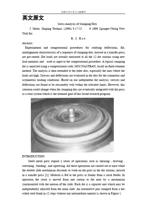
英文原文Stress Analysis of Stamping DiesJ. Mater. Shaping Technoi. (1990) 8:17-22 9 1990 Springer-Verlag New York Inc.R . S . R a oAbstract:Experimental and computational procedures for studying deflections, flit, andalignment characteristics of a sequence of stamping dies, housed in a transfer press, are pre-sented. Die loads are actually measured at all the 12 die stations using new load monitors and used as input to the computational procedure. A typical stamping die is analyzed using a computational code, MSC/NASTRAN, based on finite element method. The analysis is then extended to the other dies, especially the ones where the loads are high. Stresses and deflections are evaluated in the dies for the symmetric and asymmetric loading conditions. Based on our independent die analysis, stresses and deflections are found to be reasonably well within the tolerable limits. However, this situation could change when the stamping dies are eventually integrated with the press as a total system which is the ultimate goal of this broad research program.INTRODUCTIONSheet metal parts require a series of operations such as shearing , drawing , stretching , bending , and squeezing. All these operations are carried out at once while the double slide mechanism descends to work on the parts in the die stations, housed in a transfer press [1]. Material is fed to the press as blanks from a stock feeder. In operation the stock is moved from one station to the next by a mechanism synchronized with the motion of the slide. Each die is a separate unit which may be independently adjusted from the main slide. An automotive part stamped from a hot rolled steel blank in 12 steps without any intermediate anneals is shown in Figure 1.Transfer presses are mainly used to produce different types of automotive and aircraft parts and home appliances. The economic use of transfer presses depends upon quantity production as their usual production rate is 500 to 1500 parts per hour [2]. Although production is rapid in this way, close tolerances are often difficult to achieve. Moreover, the presses produce a set of conditions for off-center loads owing to the different operations being performed simultaneously in several dies during each stroke. Thus, the forming load applied at one station can affect the alignment and general accuracy of the operation being performed at adjacent stations. Another practical problem is the significant amount of set-up time involved to bring all the dies into proper operation. Hence, the broad goal of this research is to study the structural characteristics of press and dies combination as a total system. In this paper, experimental and computational procedures for investigating die problems are presented. The analysis of structural characteristics of the transfer press was pursued separately [3].A transfer press consisting of 12 die stations was chosen for analysis. Typical die problems are excessive deflections, tilt, and misalignment of the upperand lower die halves. Inadequate cushioning and offcenter loading may cause tilt and misalignment of the dies. Tilt and excessive deflections may also be caused by the lack of stiffness of the die bolster and the die itself. Part quality can be greatly affected by these die problems. There are a lot of other parameters such as the die design, friction and lubrication along the die work interface, speed, etc. that play a great role in producing consistently good parts. Realistically, the analysis should be carded out by incorporating the die design and the deforming characteristics of the work material such as the elastic-plastic work hardening properties. In this preliminary study, the large plastic deformation of the workpiece was not considered for the reasons mentioned below.Large deformation modeling of a sheet stretching process was carded out using the computational code based on an elastic-plastic work hardening model of the deformation process [4]. Laboratory experiments were conducted on various commercial materials using a hemispherical punch. The coefficient of friction along the punch-sheet interface was actually measured in the experiment and used as a prescribed boundary to the numerical model. Although a good solution was obtained, it was realized that the numerical analysis was very sensitive to the frictional conditions along the interface. In the most recent work, a new friction model based on the micromechanics of the asperity contact was developed [5]. In the present problem, there are several operations such as deep drawing, several reduction drawing operations, and coining, which are performed using complex die geometries. The resources and the duration of time were not adequate to study these nonlinear problems. Hence,the preliminary study was limited to die problems basedon linear stress analysis.A detailed die analysis was carried out by using MSC /NASTRAN code based on finite ele mentmethod. Die loads were.measured at all the stations using new load monitors. Such measured data were used in the numerical model to evaluate stresses and deflections in the dies for normal operating conditions and for asymmetric loading conditions. Asymmetric loading conditions were created in the analysis by tilting the dies. In real practice, it is customary to pursue trial-and-error procedures such as placing shims under the die or by adjusting the cushion pressure to correct the die alignment problems. Such time consuming tasks can be reduced or even eliminated using the computational and experimental procedures presented here.DIE GEOMETRY AND MATERIALSThe design of metal stamping dies is an inexact process. There are considerable trial-and-error adjustments during die tryout that are often required to finish the fabrication of a die that will produce acceptable parts. It involves not only the proper selection of die materials, but also dimensions. In order to withstand the pressure, a die must have proper cross-sectional area and clearances. Sharp comers, radii, fillets, and sudden changes in the cross section can have deleterious effects on the die life. In this work, the analysis was done on the existing set of dies.The dies were made of high carbon, high chromium tool steel. The hardness of this tool steel material is in the range of Rockwell C 57 to 60. Resistance to wear and galling was greatly improved by coating the dies with titanium nitride and titanium carbide. The dies were supported by several other steel holders made of alloy steels such as SAE 4140. The geometry of a typical stamping die is axisymmetric but it varies slightly from die to die depending on the operation. Detailed information about geometry andmaterials of a reduction drawing die (station number 4) was gathered from blueprints. It was reproducedin three-dimensional geometry using a preprocessor, PATRAN. One quadrant of the die is shown in Figure2. The data including geometry and elastic properties of the die material were fed to the numerical model.The work material used was hot rolled aluminumkilled steel, SAE 1008 A-K Steel and the blank thickness was about 4.5 ram. Stampings used in unexposed places or as parts of some deisgn where fine finish is not essential are usually made from hot rolled steel. The automotive part produced in this die set is a cover for a torque converter. A principal advantage of aluminum-killed steel is its minimum strain aging. EXPERIMENTAL PROCEDURESAs mentioned earlier, this research involved monitoting of die loads which were to be used in the numerical model to staldy the structural characteristicsof dies. The other advantage is to avoid overloadingthe dies in practice. Off-center loading can be detected and also set-up time can be reduced. Thus, any changes in the thickness of stock, dulling of the die,unbalanced loads, or overloadings can be detected using die load monitors.Strain gage based fiat load cells made of high grade tool steel material werefabricated and supplied by IDC Corporation. Four identical load cells were embedded in a thick rectangular plate as shown in Figure 3. They were calibrated both in the laboratory and in the plant.The plate was placed on the top of the die. The knockout pin slips through the hole in the plate. Six such plates were placed on each of six dies. In this way,24 readings can be obtained at a given time. Then they were shifted to the other six dies for complete data. All the 12 die loads are presented in Table 1.COMPUTATIONAL PROCEDURESLinear static analysis using finite element method wasused to study the effect of symmetric and asymmetric loading for this problem. A finite element model of diestation 4 was created using the graphical preprocessor, PATRAN, and the analysis was carried outusing the code MSC/NASTRA N . The code has a wideT a b l e I. Die LoadsDie Station LoadNumber (kN)1 3562 6413 2144 3565 8546 7127 2858 32O9 234910 113911 21412 2100spectrum of capabilities, of which linear static analysis is discussed here.The NASTRAN code initially generates a structural matrix and then the stiffness and the mass matrices from the data in the input file. The theoretical formulations of a static structural problem by the displacement method can be obtained from the references [6]. The unknowns are displacements and are solved for the appropriate boundary conditions. Strains are obtained from displacements. Then they are converted into stresses by using elastic stress-strain relationships of the die material.The solution procedure began with the creation of die geometry using the graphical preprocessor, PATRAN. The solution domain was divided into appropriate hyper-patches. This was followed by the generation of nodes, which were then connected by elements. Solid HEXA elements with eight nodes were used for this problem. The nodes and elements were distributed in such a way that a finer mesh was created at the critical region of the die-sheet metal interface and a coarser mesh elsewhere. The model was then optimized by deleting the unwanted nodes. The element connectivities were checked. By taking advantage of the symmetry, only one quarter of the die was analyzed. In the asymmetric case, half of the die was considered for analysis. Although, in practice, the load is applied at the top of the die, for the purpose of proper representation of the boundary conditions to the computational code, reaction forces were considered for analysis. The displacement and force boundary conditions are shown for the two cases inFigure 4.As mentioned earlier, sheet metal was not modeled in this preliminary research.As shown in Figure 4(a),the nodes on the top surface of the die were constrained (stationary surface) and the measured load of 356 kN was equally distributed on the contact nodes at the workpiece die interface. Similar boundary conditions for the punch are shown in Figure 4(b). It is noticeable that fewer nodes are in contact with the sheet metal due to the die tilt for the asymmetric loading case as shown in Figure 4(c). In real practice, the pressure actually varies along the die contact surface. Since the actual distribution was not known, uniform distribution was considered in the present analysis.DISCUSSION OF RESULTSAs described in the earlier section, the numerical analysis of die Station 4 (both the die and punch) was performed using the code MSC/NASTRAN . Two cases were considered, namely: (a) symmetric loading and (b) asymmetric loadingFig. 4. Boundary conditions. (A) Symmetric case (onequadrant of the die). (B) Symmetric case (one quadrant ofnthe punch). (C) Asymmetric case (half of the die). Symmetric LoadingNumerical analysis of the die was carried out for a measured load o f 356 kN as distributed equally in Figure 4(a). The major displacements in the loading direction are shown in Figure 5(a). These displacement contours can be shown in various colors to represent different magnitudes. The m aximum displacement value is 0.01 m m fora uniformly distributed load of 356 kN. The corresponding critical stress is very small,8.4 MPa in the y direction and 30 MPa in the x direction. The calculated displacements and stresses at the surrounding elements and nodes wereof the same order, but they decreased in magnitude at the nodes away from this critical region. Thus, the die was considered very rigid under this loading condition.Symmetric loading was applied to the punch and the numerical analysis was carried out separately. The displacement values in the protruding region of the punch were high compared to the die. The maximum displacement was 0.08 m m . It should be noted that the displacement values in this critical range of the punch were of the same order ranging from 0.05 mm to 0.08 ram. Although the load acting on the punch (bottom half) was the same as the die (upper half), that is, 356 kN, the values of displacements and stresses were higher in the punch because of the differences in the geometry. This is especially true for the protruding part of the punch. The corresponding maxim u m stress was 232 MPa. This part of the punch is still in the elastic range as the yield strength of tool steel is approximately 1034 MPa. The critical stress value might be varied for different load distributions. Since the actual distribution of the load was not known,the load was distributed equally on all nodes. As the die (upper half) is operating in a region which is extremely safe, a change in the load distribution may not produce any high critical stresses in the die. Although higher loads are applied at other die stations(see Table 1), it is concluded that the critical stresses are not going to be significantly higher due to the appropriate changesin the die geometries.Asymmetric LoadingFor the purpose of analysis, an asymmetric loading situation was created by tilting the die. Thus, only 15 nodes were in contact with the workpiece compared to 40 nodes for the symmetric loading case. As shown in Figure 4(c), a 356 kN load was uniformly distributed over the 15 nodes that were in contact with the workpiece. Although the pressure was high, because of the geometry at the location where the load was acting, the critical values of displacement and stress were found to be similar to the symmetric case. The predicted displacement and stress values were not significantly higher than the values predicted for the symmetric case.Fig. 5. Displacement contours in the loading direction. (A) Symmetric case (one quadrant of thedie). (B) Symmetric case (one quadrant of the punch). (C)Asymmetric case (half of the die).CONCLUSIONSIn this preliminary study, we have demonstrated the capabilities of the computational procedure, based on finite element method, to evaluate the stresses and deflections within the stamping dies for the measured loads. The dies were found to be within the tolerable elastic limits for both symmetric and asymmetric loading conditions. Thus the computational procedure can be used to study the tilt and alignment characteristics of stamping dies. In general, the die load monitors are very useful not only for analysis but also for on-line tonnage control. Future research involves theintegration of the structural analysis of stamping dies with that of the transfer press as a total system.ACKNOWLEDGMENTSProfessor J.G. Eisley, W.J. Anderson, and Mr. D.Londhe are thanked for their comments on this paper.REFERENCES1. R.S. Rao and A. Bhattacharya, "Transfer Process De-flection, Parallelism, and Alignment Characteristics,"Technical Report, January 1988, Department of Mechanical Engineering and Applied Mechanics, the University of Michigan, Ann Arbor.2. Editors of American Machinist, "Metalforming: Modem Machines, Methods, andTooling for Engineers and Operating Personnel," McGraw-Hill, Inc., 1982, pp. 47-50.3. W.J. Anderson, J.G. Eisley, and M.A. Tessmer,"Transfer Press Deflection, Parallelism, and Alignment Characteristics," Technical Report, January 1988, Department of Aerospace Engineering, the University of Michigan, Ann Arbor.4. B.B. Yoon, R.S. Rao, and N. Kikuchi, "Sheet Stretching: A Theoretical Experimental Comparison," International Journal of Mechanical Sciences, V ol. 31, No.8, pp. 579-590, 1989.5. B.B. Yoon, R.S. Rao, and N. Kikuchi, "Experimental and Numerical Comparisons of Sheet Stretching Using a New Friction Model," ASME Journal of Engineering Materials and Technology, in press.6. MSX/NASTRAN, McNeal Schwendler Corporation.22 9 J. Materials Shaping Technology, V ol. 8, No. 1, 1990。

外文翻译Heat Treatment of Die and Mould Oriented Concurrent Design LI Xiong,ZHANG Hong-bing,RUAN Xue —yu,LUO Zhong —hua,ZHANG YanTraditional die and mould design,mainly by experience or semi —experience ,is isolated from manufacturing process.Before the design is finalized ,the scheme of die and mould is usually modified time and again ,thus some disadvantages come into being,such as long development period,high cost and uncertain practical effect.Due to strong desires for precision,service life,development period and cost,modern die and mould should be designed and manufactured perfectly.Therefore more and more advanced technologies and innovations have been applied,for example,concurrent engineering,agile manufacturing virtual manufacturing,collaborative design,etc.Heat treatment of die and mould is as important as design,manufacture and assembly because it has a vital effect on manufacture ,assembly and service life .Design and manufacture of die and mould have progressed rapidly ,but heat treatment lagged seriously behind them .As die and mould industry develops ,heat treatment must ensure die and mould there are good state of manufacture ,assembly and wear —resistant properties by request. Impertinent heat treatment can influence die and mould manufacturing such as over —hard and —soft and assembly .Traditionally the heat treatment process was made out according to the methods and properties brought forward Abstract:Many disadvantages exist in the traditional die design method which belongsto serial pattern. It is well known that heat treatment is highly important to thedies. A new idea of concurrent design for heat treatment process of die andmould was developed in order to overcome the existent shortcomings of heattreatment process. Heat treatment CAD/CAE was integrated with concurrentcircumstance and the relevant model was built. These investigations canremarkably improve efficiency, reduce cost and ensure quality of R and D forproducts.Key words:die design; heat treatment; mouldby designer.This could make the designers of die and mould and heat treatment diverge from each other,for the designers of die and mould could not fully realize heat treatment process and materials properties,and contrarily the designers rarely understood the service environment and designing thought. These divergences will impact the progress of die and mould to a great extent. Accordingly,if the process design of heat treatment is considered in the early designing stage,the aims of shortening development period,reducing cost and stabilizing quality will be achieved and the sublimation of development pattern from serial to concurrent will be realized.Concurrent engineering takes computer integration system as a carrier,at the very start subsequent each stage and factors have been considered such as manufacturing,heat treating,properties and so forth in order to avoid the error.The concurrent pattern has dismissed the defect of serial pattern,which bring about a revolution against serial pattern.In the present work.the heat treatment was integrated into the concurrent circumstance of the die and mould development,and the systemic and profound research was performed.1 Heat Treatment Under Concurrent CircumstanceThe concurrent pattern differs ultimately from the serial pattern(see Fig.1).With regard to serial pattern,the designers mostly consider the structure and function of die and mould,yet hardly consider the consequent process,so that the former mistakes are easily spread backwards.Meanwhile,the design department rarely communicates with the assembling,cost accounting and sales departments.These problems certainly will influence the development progress of die and mould and the market foreground.Whereas in the concurrent pattern,the relations among departments are close,the related departments all take part in the development progress of die and mould and have close intercommunion with purchasers.This is propitious to elimination of the conflicts between departments,increase the efficiency and reduce the cost.Heat treatment process in the concurrent circumstance is made out not after blueprint and workpiece taken but during die and mould designing.In this way,it is favorable to optimizing the heat treatment process and making full use of the potential of the materials.2 Integration of Heat Treatment CAD/CAE for Die and MouldIt can be seen from Fig.2 that the process design and simulation of heat treatment are the core of integration frame.After information input via product design module and heat treatment process generated via heat treatment CAD and heat treatment CAE module will automatically divide the mesh for parts drawing,simulation temperature field microstructure analysis after heat—treatment and the defect of possible emerging (such as overheat,over burning),and then the heat treatment process is judged if the optimization is made according to the result reappeared by stereoscopic vision technology.Moreover tool and clamping apparatus CAD and CAM are integrated into this system.The concurrent engineering based integration frame can share information with other branch.That makes for optimizing the heat treatment process and ensuring the process sound.2.1 3-D model and stereoscopic vision technology for heat treatmentThe problems about materials,structure and size for die and mould can be discovered as soon as possible by 3-D model for heat treatment based on the shape of die and mould.Modeling heating condition and phase transformation condition for die and mould during heat treatment are workable,because it has been broken through for the calculation of phase transformation thermodynamics,phase transformation kinetics,phase stress,thermal stress,heat transfer,hydrokinetics etc.For example,3-D heat—conducting algorithm models for local heating complicated impression and asymmetric die and mould,and M ARC software models for microstructure transformation was used.Computer can present the informations of temperature,microstructure and stress at arbitrary time and display the entire transformation procedure in the form of 3-D by coupling temperature field,microstructure field and stress field.If the property can be coupled,various partial properties can be predicted by computer.2.2 Heat treatment process designDue to the special requests for strength,hardness,surface roughness and distortion during heat treatment for die and mould,the parameters including quenching medium type,quenching temperature and tempering temperature and time,must be properlyselected,and whether using surface quenching or chemical heat treatment the parameters must be rightly determined.It is difficult to determine the parameters by computer fully.Since computer technology develops quickly in recent decades,the difficulty with large—scale calculation has been overcome.By simulating and weighing the property,the cost and the required period after heat treatment.it is not difficult to optimize the heat treatment process.2.3 Data base for heat treatmentA heat treatment database is described in Fig.3.The database is the foundation of making out heat treatment process.Generally,heat treatment database is divided into materials database and process database.It is an inexorable trend to predict the property by materials and process.Although it is difficult to establish a property database,it is necessary to establish the database by a series of tests.The materials database includes steel grades,chemical compositions,properties and home and abroad grades parallel tables.The process database includes heat treatment criterions,classes,heat preservation time and cooling velocity.Based on the database,heat treatment process can be created by inferring from rules.2.4 Tool and equipment for heat treatmentAfter heat treatment process is determined,tool and equipment CAD/CAE systemtransfers the information about design and manufacture to the numerical control device.Through rapid tooling prototype,the reliability of tool and the clamping apparatus can be judged.The whole procedure is transferred by network,in which there is no man—made interference.3 Key Technique3.1 Coupling of temperature,microstructure,stress and propertyHeat treatment procedure is a procedure of temperature-microstructure—stress interaction.The three factors can all influence the property (see Fig.4).During heating and cooling,hot stress and transformation will come into being when microstructure changes.Transformation temperature-microstructure and temperature—microstructure—and stress-property interact on each other.Research on the interaction of the four factors has been greatly developed,but the universal mathematic model has not been built.Many models fit the test nicely,but they cannot be put into practice.Difficulties with most of models are solved in analytic solution,and numerical method is employed so that the inaccuracy of calculation exists.Even so,comparing experience method with qualitative analysis,heat treatment simulation by computer makes great progress.3.2 Establishment and integration of modelsThe development procedure for die and mould involves design,manufacture,heat treatment,assembly,maintenance and so on.They should have own database and mode1.They are in series with each other by the entity—relation model.Through establishing and employing dynamic inference mechanism,the aim of optimizing design can be achieved.The relation between product model and other models was built.The product model will change in case the cell model changes.In fact,it belongs to the relation of data with die and mould.After heat treatment model is integrated into the system,it is no more an isolated unit but a member which is close to other models in the system.After searching,calculating and reasoning from the heat treatment database,procedure for heat treatment,which is restricted by geometric model,manufacture model for die and mould and by cost and property,is obtained.If the restriction is disobeyed,the system will send out the interpretative warning.All design cells are connected by communication network.3.3 Management and harmony among membersThe complexity of die and mould requires closely cooperating among item groups.Because each member is short of global consideration for die and mould development,they need to be managed and harmonized.Firstly,each item group should define its own control condition and resource requested,and learn of the request of up- and-down working procedure in order to avoid conflict.Secondly,development plan should be made out and monitor mechanism should be established.The obstruction can be duly excluded in case the development is hindered.Agile management and harmony redound to communicating information,increasing efficiency,and reducing redundancy.Meanwhile it is beneficial for exciting creativity,clearing conflict and making the best of resource.4 Conclusions(1) Heat treatment CAD/CAE has been integrated into concurrent design for die and mould and heat treatment is graphed,which can increase efficiency,easily discover problems and clear conflicts.(2)Die and mould development is performed on the same platform.When the heat treatment process is made out,designers can obtain correlative information and transfer self-information to other design departments on the platform.(3)Making out correct development schedule and adjusting it in time can enormously shorten the development period and reduce cost.References:[1] ZHOU Xiong-hui,PENG Ying-hong.The Theory and Technique of Modern Die and Mould Design and Manufacture[M].Shanghai:Shanghai Jiaotong University Press 2000(in Chinese).[2] Kang M,Park& Computer Integrated Mold Manufacturing[J].Int J Computer Integrated Manufacturing,1995,5:229-239.[3] Yau H T,Meno C H.Concurrent Process Planning for Finishing Milling and Dimensional Inspection of Sculptured Surface in Die and Mould Manufacturing[J].Int J Product Research,1993,31(11):2709—2725.[4] LI Xiang,ZHOU Xiong-hui,RUAN Xue-yu.Application of Injection Mold Collaborative Manufacturing System [J].JournaI of Shanghai Jiaotong University,2000,35(4):1391-1394.[5] Kuzman K,Nardin B,Kovae M ,et a1.The Integration of Rapid Prototyping and CAE in Mould Manufacturing[J].J Materials Processing Technology,2001,111:279—285.[6] LI Xiong,ZHANG Hong—bing,RUAN Xue-yu,et a1.Heat Treatment Process Design Oriented Based on Concurrent Engineering[J].Journal of Iron and Steel Research,2002,14(4):26—29.文献出处:LI Xiong,ZHANG Hong-bing,RUAN Xue—yu,LUO Zhong—hua,ZHANG Yan.Heat Treatment of Die and Mould Oriented Concurrent Design[J].Journal of Iron and Steel Research,2006,13(1):40- 43,74模具热处理及其导向平行设计李雄,张鸿冰,阮雪榆,罗中华,张艳摘要:在一系列方式中,传统模具设计方法存在许多缺点。
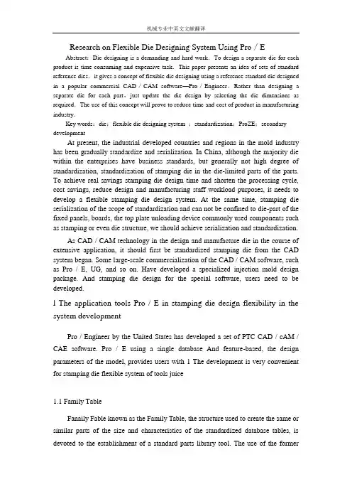
Research on Flexible Die Designing System Using Pro/EAbstract:Die designing is a demanding and hard work.To design a separate die for each product is time consuming and expensive task.This paper presents an idea of sets of standard reference dies.it gives a concept of flexible die designing using a reference standard die designed in a popular commercial CAD/CAM software—Pro/Engineer.Rather than designing a separate die for each part,just update the die design by selecting the die dimensions as required.The use of this concept will prove to reduce time and cost of product in manufacturing industry.Key words:die;flexible die designing system ;standardization;ProZE;secondary developmentAt present, the industrial developed countries and regions in the mold industry has been gradually standardize and serialization. In China, although the majority die within the enterprises have business standards, but generally not high degree of standardization, standardization of stamping die in the die-limited parts of the parts. To achieve real savings stamping die design time and shorten the processing cycle, cost savings, reduce design and manufacturing staff workload purposes, it needs to develop a flexible stamping die design system. At the same time, stamping die serialization of the scope of standardization and can not be confined to die-part of the fixed panels, boards, the top plate unloading device commonly used components such as stamping or even die structure, we should achieve serialization and standardization.As CAD / CAM technology in the design and manufacture die in the course of extensive application, it should first be standardized stamping die from the CAD system began. Some large-scale commercialization of the CAD / CAM software, such as Pro / E, UG, and so on. Have developed a specialized injection mold design package. And stamping die design for the special software, users need to be developed.l The application tools Pro / E in stamping die design flexibility in the system developmentPro / Engineer by the United States has developed a set of PTC CAD / cAM / CAE software. Pro / E using a single database And feature-based, the design parameters of the model, provides users with 1 The development is very convenient for stamping die flexible system of tools juice1.1 Family TableFanaily Fable known as the Family Table, the structure used to create the same or similar parts of the size and characteristics of the standardized database tables, is devoted to the establishment of a standard parts library tool. The use of the formerfirst family table to create a generic representation of the components (the generic), according to the need to target and then added to the family table a series of management.Family sheet management can be the object of a size (dimension), features (feature), parameters (parameter) and assembly parts (component), and so on.A family table can have multiple levels, that is a generic parts can contain multiple sub-components (instance, also known as examples), and each Instance can contain their own Sub Instance. Discharge screw (stripper-bolt) the family table structure as shown in Figure 1.Figure 1 Family Table hierarchy1.2 RelationsRelations (relations) between mathematics and procedures, including grammar, and its main role is to be part or assembly of the relevance of the data by size symbols, and other parameters of grammar (syntax) to establish mathematical formula to meet the design requirements. Pro / E system of relations can be found in Sketch, Feature, Part and in the Assembly. Simple sentence, judgement and sentence is to establish relations of common format. Simple sentence that a simple mathematical relationship between the size of direct response associated situation. The use of simple format, such as d6 = L. BP 1 2 * d3. Judgement on the sentence for certain occasions, by specifying conditions to express design intent, grammar structure: "IF… ENDIF" or "IF… ELSE… ENDIF" in the "ELSE… ENDIF" between conditional statements can be multi-nested. Relations in the standardization and flexible stamping die design system in the building process plays a very important role, it has decided to parts of the geometric shape and characteristics of relations between the digital Xiao, partsrelations between the assembly and parts assembly in the presence of middle - A number of features.1.3 Pro/ProgramPro / Program (program) is the Pro / E of a procedural tool, similar to its grammar VBA and Office software in the Macro (Acer). When users use of Pro / engineer to design .The product of various kinds of information to document the format will be recorded. Through the Pro / Progran document editing, can be achieved on the characteristics of the hide, delete and re-order the assembly of components to add and replacement operation. These features stamping dies for the establishment of standard parts library, standards and flexible design structure of the system is very useful.Program files in the structure can be broadly classified into the title, set of parameters relationship, to add features (parts) and updating the quality attributes, such as five parts. In "INPUT… END INPUT" Xiao located between the parameters of the "RE1 ATIONS… ENDREALATIONS" relations between the various add in the "ADD… END ADD" and added features (part mo dule) or parts (assembly module). Pro / Program provides three types of parameters: NUMBER (numerical) STRING (string) and YES-NO (it).2. Standards moldbase of the development2.1 Standards moldbase Classification and organizationsDie-stamping die is an important part. The typical model-there are three types: rear-guided-mode (back pillar sets), the middle-guided-mode (center pillar sets) and the guided-mode-angle (diagonal pillarsets). Each type of die-also includes a variety of specifications. According to Die boundary demarcation size, rear-guided, in a L × B-22 specifications, D0 specifications 6 (L = B), middle-guided, in the nine-D0 specifications, the guided-mode-Kok L × B specifications 7 [2-3].In order to facilitate the management and data calls, the standard mode of the directory of the best-established in the Pro / E installation directory. As three categories-the larger structural differences, it may die-the root of the establishment of three other subdirectories, each subdirectory contains all the component parts-mode, and each type of parts can be adopted Pro / E Software for the family table, and toolssuch as the establishment of standard procedures for the database.2.2 Standards moldbase library buildingDie-stamping die from the main mode on the Block (upper.shoe), nder-Block (1 ower.shoe), I. column (guide.pillar) and I. Case (guidebushing), and other components. In order to make structural integrity of mold, can also die stalk (shank) assembly to die-in. Here are rear-die I.Establishment of the standard method.First of all the various components to create three-dimensional model, and then the standard manual data in the table a series of symbolic dimension added to the group on January 1 Editor (can also use Excel for editing). Add in the size of symbols, Size will be the best symbol to revise the manual and the size of the same symbol. Because people can not distinguish between Table Capitalization is, when both the same size letters, proposed to use capital letters to distinguish between pairs of characters, such as that for the d D, and D that will become a DD.Standard on two-Block: When the L ×B> 200 mm ×160 mn-i have installed Boss, and when L × B is less than or equal to the scope of non-installation of Boss, shown in Figure 2. Determine whether Boss in two ways: one way is to use Family Table, will generate the Boss Extrude Offset two characteristics and the way to Feature added to the family table, and in these two characteristics of the list Enter in the "Y" or "N", to determine the specifications of a certain mode on the Block, whether these two features; Another method is to find these two features in the Pro / Program in the location and characteristics of the process to add Extrude His statement before the judge "IF L> 200 1 B> 160", adding the Offset characteristics of the procedures used "END IF" the end of judgement.Figure2. die on the ground in two types2.3 The establishment of Standards moldbase forIn Pro / Assembly in the same module can be generated by the use of family die-standard database. Family structure in the assembly, when selected COrnponent, select the mode of all the parts-and enter a different group in the table-model specifications required by the standards of sub-components of the name, as shown in Figure 3.Figure 3 rear-guided, in the standard mode of Family TableCommon mode handles four types: pressure-in-stalk, the flange-stalk, Screw-mode and floating stems die stalk. If the four types of module assembly to handle all the common-mode model (Figure 3 in the assembly only two kinds), in the group table by the need to enter the module handles parts of the name, set the parameters of INPUT, with Regenerate Called when the parameters of renewable order to choose the mode of different types of handles. Of course, people can also die of the table do not have to handle characters with "N" to curb, as shown in Figure 3-mode system is used in this method.3 The development of standard stamping die3.1 The typical combination of stamping dieStamping die in the larger structural differences and establish flexible stamping die design systems using the best combination of the typical mold. Use of combinations to determine the structure of the typical mold of the structure, and thus determine the composition of the various components die sizes and assembly relations. Commonly used combination of stamping die typical structure: a fixed combinationof unloading, Tanya unloading combinations, composite model portfolio, such as plate-portfolio. Mold can not be separated from the structure of ISO standardization of parts, in the Pro / Engineer Dies in the standardization of parts can be used in the design of the bottom-up approach can also be used top-down design.3.2 die in the process of assembling data transferBecause of complicated, so stamping die by the standardization of the factors to consider-Modulus than standardized by many more factors to consider, one of the most important factor is the size of the correlation between the components. In the mold of a standard combination, assembly and components, parts and components between the need for data transmission, and in the Pro / Assembly can be very easy to achieve this objective.3.2.1 by the assembly of components to the data transferPro / Program can use the assembly EXECUTE statement will be down the parameters in a sub-assembly or parts delivery, the use of syntax is as follows: EXECUTE PART / ASSEMBLY file name components or sub-assembly of the parameters in the assembly of = END EXECUTE EXECUTE statement parameters can not leapfrog data transmission, not by the assembly to sub-assembly of components in the direct transmission of data.3.2.2 data transfer between the componentsWhen added to the assembly of components are in a Id, it can complete the assembly of components between the data transfer. Id assembly of components, can be used in the menu RELATIONs Session Id command to query. Figure 4 is the combination of Tanya discharge standards in the spring of unloading assembly diagram. As assembly to die in the spring have a pre-compression and thus the length of its assembly (Hs) are no longer equal to the length of freedom (H.). In determining H, you can use the following mathematical relationship:Hs:38= L:32一tbp:0In this way can always guarantee equal to the length of spring assembly from the surface to Dianban discharge board under the surface height, thus eliminating the relevant parts were replaced after the size of Laws. In the design of this mold is very practical, because the mold assembly in a similar situation there are many. Again, in determining the discharge screw on the seat-hole diameter (dI34), they can use thefollowing mathematical relationship:d134:8=D:32+2This Id, established by the mathematical relationship between the need to use Regenerate order to take effect, so different parts on the size of the location of as little as possible in this way, so as not to die in the initial call model will appear at the wrong result will be displayed. But if the parts in between and parameters to transfer data, the location of the various components of size parameters to create a mathematical relationship, the trouble can be avoided.3.2.3 standard replacement partsFamily Table used to establish the standard parts can lookup. inst Replacement statement. Lookup inst allows users to find the standard parts that match the sub-components, if not find the results, then return to a generic [4 J.Lookup.inst :lookup inst(generic—name,match-mode,paramnamel,match—valuel,param-name2,match—value2…)One match. preferred mode of three, representing different meanings: one is to find parameters of less than or equal to find the value of components; parameter values 0 to find an exact match to find value of the sub-components; to find parameters of greater than or equal to find value The sub-components.3.3 structure of the assemblyDie parts to complete the establishment and rationalize the assembly relations between the components, you can generate mold assembly model. Figure 5 for the development of the author Tanya unloading combination of specifications for the 200 mm × 160 mm of die structure (omit all the characteristics of thread).3.4 stamping die callStamping die in the Pro / Assembly call directly, but also can be used Pro / TOOLKIT development of visual user interface to call. Pro / TOOLKIT Pro Ecuador is the second development system software package, its main purpose is to allowusers or third parties through the expansion of C code Pro / E function, based on the development of Pro / E system of application modules to meet user Special needs. Pro/T00LKIT use of the UI dialog, the menu VC + + and Visual Interface technology, designed to facilitate flexible and practical stamping die design system for interactive interface. Use interface called the structure of various stamping dies, the choice of different specifications of the parts, enter a different parameters to determine sheet parameters as well as their positioning in the mold, and further in the system design punch, die and other structures, Thus greatly enhance the efficiency of stamping die design.4 ConclusionSince stamping process a wide range of complex processes, and the shape of various parts die, stamping dies in achieving standardization and development of flexible design system and the process is very complicated, but flexible stamping die design system of stamping die CAD is to improve the level of the cornerstones . Pro / E powerful components, the assembly of the criteria for the establishment of the functions of stamping dies for the standardization and flexible design of the feasibility of developing systems to provide a strong guarantee. In the development of flexible design system, should ingenious application of Pro / E software provided by an effective tool, considering the different types of standard structural composition of the assembly relations. Between the parts and components meet requirements of size structure changes, and the best use RELATIONS Pro / Program prepared by the mathematical relations systems and procedures to increase the flexibility and practicality. Die flexible design and application development system to avoid a mold designers unnecessary duplication of labor, so that the programme will focus on the concept, process optimization, and other creative work, thus mold the rapid design and production standards have a practical application Significance.冲压模具柔性设计系统的研究摘要:冲压模具设计是一项十分复杂的工作。
冲压模具成型外文翻译参考文献冲压模具成型外文翻译参考文献(文档含中英文对照即英文原文和中文翻译)4 Sheet metal forming and blanking4.1 Principles of die manufacture4.1.1 Classification of diesIn metalforming,the geometry of the workpiece is established entirely or partially by the geometry of the die.In contrast to machining processes,ignificantly greater forces are necessary in forming.Due to the complexity of the parts,forming is often not carried out in a single operation.Depending on the geometry of the part,production is carried out in several operational steps via one or several production processes such as forming or blanking.One operation can also include several processes simultaneously(cf.Sect.2.1.4).During the design phase,the necessary manufacturing methods as well as the sequence and number of production steps are established in a processing plan(Fig.4.1.1).In this plan,theavailability of machines,the planned production volumes of the part and other boundary conditions are taken into account.The aim is to minimize the number of dies to be used while keeping up a high level of operational reliability.The parts are greatly simplified right from their design stage by close collaboration between the Part Design and Production Departments in order to enable several forming and related blanking processes to be carried out in one forming station.Obviously,the more operations which are integrated into a single die,the more complex the structure of the die becomes.Theconsequences are higher costs,a decrease in output and a lower reliability.Fig.4.1.1 Production steps for the manufacture of an oil sump Types of diesThe type of die and the closely related transportation of the part between dies is determined in accordance with the forming procedure,the size of the part in question and the production volume of parts to be produced.The production of large sheet metal parts is carried out almost exclusively using single sets of dies.Typical parts can be found in automotive manufacture,the domestic appliance industry and radiator production.Suitable transfer systems,for example vacuum suction systems,allow the installation of double-action dies in a sufficiently large mounting area.In this way,for example,the right and left doors of a car can be formed jointly in one working stroke(cf.Fig.4.4.34).Large size single dies are installed in large presses.The transportation of the parts from oneforming station to another is carried out mechanically.In a press line with single presses installed one behind the other,feeders or robots can be used(cf.Fig.4.4.20 to 4.4.22),whilst in large-panel transfer presses,systems equipped with gripper rails(cf.Fig.4.4.29)or crossbar suction systems(cf.Fig.4.4.34)are used to transfer the parts.Transfer dies are used for the production of high volumes of smaller and medium size parts(Fig.4.1.2).They consist of several single dies,which are mounted on a common base plate.The sheet metal is fed through mostly in blank form and also transported individually from die to die.If this part transportation is automated,the press is called a transfer press.The largest transfer dies are used together with single dies in large-panel transfer presses(cf.Fig.4.4.32).In progressive dies,also known as progressive blanking dies,sheet metal parts are blanked in several stages;generally speaking no actual forming operation takes place.The sheet metal is fed from a coil or in the form of metal ing an appropriate arrangement of the blanks within the available width of the sheet metal,an optimal material usage is ensured(cf.Fig.4.5.2 to 4.5.5). The workpiece remains fixed to the strip skeleton up until the laFig.4.1.2 Transfer die set for the production of an automatic transmission for an automotive application-st operation.The parts are transferred when the entire strip is shifted further in the work flow direction after the blanking operation.The length of the shift is equal to the center line spacing of the dies and it is also called the step width.Side shears,very precise feeding devices or pilot pins ensure feed-related part accuracy.In the final production operation,the finished part,i.e.the last part in the sequence,is disconnected from the skeleton.A field of application for progressive blanking tools is,for example,in the production of metal rotors or stator blanks for electric motors(cf.Fig.4.6.11 and 4.6.20).In progressive compound dies smaller formed parts are produced in several sequential operations.In contrast to progressive dies,not only blanking but also forming operations areperformed.However, the workpiece also remains in the skeleton up to the last operation(Fig.4.1.3 and cf.Fig.4.7.2).Due to the height of the parts,the metal strip must be raised up,generally using lifting edges or similar lifting devices in order to allow the strip metal to be transported mechanically.Pressed metal parts which cannot be produced within a metal strip because of their geometrical dimensions are alternatively produced on transfer sets.Fig.4.1.3 Reinforcing part of a car produced in a strip by a compound die setNext to the dies already mentioned,a series of special dies are available for special individual applications.These dies are,as a rule,used separately.Special operations make it possible,however,for special dies to be integrated into an operational Sequence.Thus,for example,in flanging dies several metal parts can be joined together positively through the bending of certain metal sections(Fig.4.1.4and cf.Fig.2.1.34).During this operation reinforcing parts,glue or other components can be introduced.Other special dies locate special connecting elements directly into the press.Sorting and positioning elements,for example,bring stamping nuts synchronised with the press cycles into the correct position so that the punch heads can join them with the sheet metal part(Fig.4.1.5).If there is sufficient space available,forming and blanking operations can be carried out on the same die.Further examples include bending,collar-forming,stamping,fine blanking,wobble blanking and welding operations(cf.Fig.4.7.14 and4.7.15).Fig.4.1.4 A hemming dieFig.4.1.5 A pressed part with an integrated punched nut4.1.2 Die developmentTraditionally the business of die engineering has been influenced by the automotive industry.The following observations about the die development are mostly related to body panel die construction.Essential statements are,however,made in a fundamental context,so that they are applicable to all areas involved with the production of sheet-metal forming and blanking dies.Timing cycle for a mass produced car body panelUntil the end of the 1980s some car models were still being produced for six to eight years more or less unchanged or in slightly modified form.T oday,however,production time cycles are set for only five years or less(Fig.4.1.6).Following the new different model policy,the demands ondie makers have alsochanged prehensive contracts of much greater scope such as Simultaneous Engineering(SE)contracts are becoming increasingly common.As a result,the die maker is often involved at the initial development phase of the metal part as well as in the planning phase for the production process.Therefore,a muchbroader involvement is established well before the actual die development is initiated.Fig.4.1.6 Time schedule for a mass produced car body panel The timetable of an SE projectWithin the context of the production process for car body panels,only a minimal amount of time is allocated to allow for the manufacture of the dies.With large scale dies there is a run-up period of about 10 months in which design and die try-out areincluded.In complex SE projects,which have to be completed in 1.5 to 2 years,parallel tasks must be carried out.Furthermore,additional resources must be provided before and after delivery of the dies.These short periods call for pre-cise planning,specific know-how,available capacity and the use of the latest technological and communications systems.The timetable shows the individual activities during the manufacturing of the dies for the production of the sheet metal parts(Fig.4.1.7).The time phases for large scale dies are more or less similar so that this timetable can be considered to be valid in general.Data record and part drawingThe data record and the part drawing serve as the basis for all subsequent processing steps.They describe all the details of the parts to be produced. The information given in theFig.4.1.7 Timetable for an SE projectpart drawing includes: part identification,part numbering,sheet metal thickness,sheet metal quality,tolerances of the finished part etc.(cf.Fig.4.7.17).To avoid the production of physical models(master patterns),the CAD data should describe the geometry of the part completely by means of line,surface or volume models.As ageneral rule,high quality surface data with a completely filleted and closed surface geometry must be made available to all the participants in a project as early as possible.Process plan and draw developmentThe process plan,which means the operational sequence to be followed in the production of the sheet metal component,is developed from the data record of the finished part(cf.Fig.4.1.1).Already at this point in time,various boundary conditions must be taken into account:the sheet metal material,the press to be used,transfer of the parts into the press,the transportation of scrap materials,the undercuts as well as thesliding pin installations and their adjustment.The draw development,i.e.the computer aided design and layout of the blank holder area of the part in the first forming stage–if need bealso the second stage–,requires a process planner with considerable experience(Fig.4.1.8).In order to recognize and avoid problems in areas which are difficult to draw,it is necessary to manufacture a physical analysis model of the draw development.With this model,theforming conditions of the drawn part can be reviewed and final modifications introduced,which are eventually incorporated into the data record(Fig.4.1.9).This process is being replaced to some extent by intelligent simulation methods,through which the potential defects of the formed component can be predicted and analysed interactively on the computer display.Die designAfter release of the process plan and draw development and the press,the design of the die can be started.As a rule,at thisstage,the standards and manufacturing specifications required by the client must be considered.Thus,it is possible to obtain a unified die design and to consider the particular requests of the customer related to warehousing of standard,replacement and wear parts.Many dies need to be designed so that they can be installed in different types of presses.Dies are frequently installed both in a production press as well as in two different separate back-up presses.In this context,the layout of the die clamping elements,pressure pins and scrap disposal channels on different presses must be taken into account.Furthermore,it must be noted that drawing dies working in a single-action press may be installed in a double-action press(cf.Sect.3.1.3 and Fig.4.1.16).Fig.4.1.8 CAD data record for a draw developmentIn the design and sizing of the die,it is particularly important to consider the freedom of movement of the gripper rail and the crossbar transfer elements(cf.Sect.4.1.6).These describe the relative movements between the components of the press transfer system and the die components during a complete press working stroke.The lifting movement of the press slide,theopening and closing movements of the gripper rails and the lengthwise movement of the whole transfer are all superimposed.The dies are designed so that collisions are avoided and a minimum clearance of about 20 mm is set between all the moving parts.4 金属板料的成形及冲裁4. 模具制造原理4.1.1模具的分类在金属成形的过程中,工件的几何形状完全或部分建立在模具几何形状的基础上的。
外文文献翻译(含:英文原文及中文译文)英文原文Stamping technologyIntroductionIn the current fierce market competition, the product to market sooner or later is often the key to the success or failure. Mould is a product of high quality, high efficiency production tool, mold development cycle of the main part of the product development cycle. So the customer requirements for mold development cycle shorter, many customers put the mould delivery date in the first place, and then the quality and price. Therefore, how to ensure the quality, control the cost under the premise of processing mould is a problem worthy of serious consideration. Mold processing technology is an advanced manufacturing technology, has become an important development direction, in the aerospace, automotive, machinery and other industries widely used. Mold processing technology, can improve the comprehensive benefit and competitiveness of manufacturing industry. Research and establish mold process database, provide production enterprises urgently need to high speed cutting processing data, to the promotion of high-speed machining technology has very important significance. This article's main goal is to build a stamping die processing, mold manufacturing enterprises in theactual production combined cutting tool, workpiece and machine tool with the actual situation of enterprise itself accumulate to high speed cutting processing instance, process parameters and experience of high speed cutting database selectively to store data, not only can save a lot of manpower and material resources, financial resources, but also can guide the high speed machining production practice, to improve processing efficiency, reduce the tooling cost and obtain higher economic benefits.1. The concept, characteristics and application of stampingStamping is a pressure processing method that uses a mold installed on a press machine (mainly a press) to apply pressure to a material to cause it to separate or plastically deform, thereby obtaining a desired part (commonly referred to as a stamped or stamped part). Stamping is usually cold deformation processing of the material at room temperature, and the main use of sheet metal to form the required parts, it is also called cold stamping or sheet metal stamping. Stamping is one of the main methods of material pressure processing or plastic processing, and is affiliated with material forming engineering.The stamping die is called stamping die, or die. Dies are special tools for the batch processing of materials (metal or non-metallic) into the required stampings. Stamping is critical in stamping. There is no die that meets the requirements. Batch stamping production is difficult. Without advanced stamping, advanced stamping processes cannot be achieved.Stamping processes and dies, stamping equipment, and stamping materials constitute the three elements of stamping. Only when they are combined can stampings be obtained.Compared with other methods of mechanical processing and plastic processing, stamping processing has many unique advantages in both technical and economic aspects, and its main performance is as follows;(1) The stamping process has high production efficiency, easy operation, and easy realization of mechanization and automation. This is because stamping is accomplished by means of die and punching equipment. The number of strokes for ordinary presses can reach several tens of times per minute, and the high-speed pressure can reach hundreds or even thousands of times per minute, and each press stroke is You may get a punch.(2) Since the die ensures the dimensional and shape accuracy of the stamping part during stamping, and generally does not destroy the surface quality of the stamping part, the life of the die is generally longer, so the stamping quality is stable, the interc hangeability is good, and it has “the same” Characteristics.(3) Stamping can process parts with a wide range of sizes and shapes, such as stopwatches as small as clocks, as large as automobile longitudinal beams, coverings, etc., plus the cold deformation hardening effect of materials during stamping, the strength of stamping and Thestiffness is high.(4) Stamping generally does not generate scraps, material consumption is less, and no other heating equipment is required. Therefore, it is a material-saving and energy-saving processing method, and the cost of stamping parts is low.However, the molds used for stamping are generally specialized, and sometimes a complex part requires several sets of molds for forming, and the precision of the mold manufacturing is high and the technical requirements are high. It is a technology-intensive product. Therefore, the advantages of stamping can only be fully realized in the case of large production volume of stamping parts, so as to obtain better economic benefits.Stamping is widely used in modern industrial production, especially in mass production. A considerable number of industrial sectors are increasingly using punching to process product components such as automobiles, agricultural machinery, instruments, meters, electronics, aerospace, aerospace, home appliances, and light industry. In these industrial sectors, the proportion of stamped parts is quite large, at least 60% or more, and more than 90%. Many of the parts that were manufactured in the past using forging = casting and cutting processes are now mostly replaced by light-weight, rigid stampings. Therefore, it can be said that if the stamping process cannot be adopted in production, it isdifficult for many industrial departments to increase the production efficiency and product quality, reduce the production cost, and quickly replace the product.2. Basic process and mould for stampingDue to the wide variety of stamped parts and the different shapes, sizes, and precision requirements of various parts, the stamping process used in production is also varied. Summarized, can be divided into two major categories of separation processes and forming processes; Separation process is to make the blank along a certain contour line to obtain a certain shape, size and section quality stamping (commonly referred to as blanking parts) of the process; forming process refers to The process of producing a stamped part of a certain shape and size by plastic deformation of the blank without breaking.The above two types of processes can be divided into four basic processes: blanking, bending, deep drawing and forming according to different basic deformation modes. Each basic process also includes multiple single processes.In actual production, when the production volume of the stamped part is large, the size is small and the tolerance requirement is small, it is not economical or even difficult to achieve the requirement if the stamping is performed in a single process. At this time, a centralized scheme is mostly used in the process, that is, two or more singleprocesses are concentrated in a single mold. Different methods are called combinations, and they can be divided into compound-graded and compound- Progressive three combinations.Composite stamping - A combination of two or more different single steps at the same station on the die in one press stroke.Progressive stamping - a combination of two or more different single steps on a single work station in the same mold at a single working stroke on the press.Composite - Progressive - On a die combination process consisting of composite and progressive two ways.There are many types of die structure. According to the process nature, it can be divided into blanking die, bending die, drawing die and forming die, etc.; the combination of processes can be divided into single-step die, compound die and progressive die. However, regardless of the type of die, it can be regarded as consisting of two parts: the upper die and the lower die. The upper die is fixed on the press table or the backing plate and is a fixed part of the die. During work, the blanks are positioned on the lower die surface by positioning parts, and the press sliders push the upper die downwards. The blanks are separated or plastically deformed under the action of the die working parts (ie, punch and die) to obtain the required Shape and size of punching pieces. When the upper mold is lifted, the unloading and ejecting device of the moldremoves or pushes and ejects the punching or scrap from the male and female molds for the next punching cycle.3. Current status and development direction of stamping technologyWith the continuous advancement of science and technology and the rapid development of industrial production, many new technologies, new processes, new equipment, and new materials continue to emerge, thus contributing to the constant innovation and development of stamping technology. Its main performance and development direction are as follows:(1) The theory of stamping and the stamping process The study of stamping forming theory is the basis for improving stamping technology. At present, the research on the stamping forming theory at home and abroad attaches great importance, and significant progress has been made in the study of material stamping performance, stress and strain analysis in the stamping process, study of the sheet deformation law, and the interaction between the blank and the mold. . In particular, with the rapid development of computer technology and the further improvement of plastic deformation theory, computer simulation techniques for the plastic forming process have been applied at home and abroad in recent years, namely the use of finite element (FEM) and other valuable analytical methods to simulate the plastic forming process of metals. According to the analysis results, the designer can predict the feasibility and possiblequality problems of a certain process scheme. By selecting and modifying the relevant parameters on the computer, the process and mold design can be optimized. This saves the cost of expensive trials and shortens the cycle time.Research and promotion of various pressing technologies that can increase productivity and product quality, reduce costs, and expand the range of application of stamping processes are also one of the development directions of stamping technology. At present, new precision, high-efficiency, and economical stamping processes, such as precision stamping, soft mold forming, high energy high speed forming, and dieless multi-point forming, have emerged at home and abroad. Among them, precision blanking is an effective method for improving the quality of blanking parts. It expands the scope of stamping processing. The thickness of precision blanking parts can reach 25mm at present, and the precision can reach IT16~17; use liquid, rubber, polyurethane, etc. Flexible die or die soft die forming process can process materials that are difficult to process with ordinary processing methods and parts with complex shapes, have obvious economic effects under specific production conditions, and adopt energy-efficient forming methods such as explosion for processing. This kind of sheet metal parts with complex dimensions, complex shapes, small batches, high strength and high precision has important practical significance; Superplastic forming of metal materialscan be used to replace multiple common stampings with one forming. Forming process, which has outstanding advantages for machining complex shapes and large sheet metal parts; moldless multi-point forming process is an advanced technology for forming sheet metal surfaces by replacing the traditional mold with a group of height adjustable punches. Independently designed and manufactured an international leading-edge moldless multi-point forming equipment, which solves the multi-point press forming method and can therefore be Changing the state of stress and deformation path, improving the forming limit of the material, while repeatedly using the forming technology may eliminate the residual stress within the material, the rebound-free molding. The dieless multi-point forming system takes CAD/CAM/CAE technology as the main means to quickly and economically realize the automated forming of three-dimensional surfaces.(2) Dies are the basic conditions for achieving stamping production. In the design and manufacture of stampings, they are currently developing in the following two aspects: On the one hand, in order to meet the needs of high-volume, automatic, precision, safety and other large-volume modern production, stamping is To develop high-efficiency, high-precision, high-life, multi-station, and multi-function, compared with new mold materials and heat treatment technologies, various high-efficiency, precision, CNC automatic mold processing machine toolsand testing equipment and molds CAD/CAM technology is also rapidly developing; On the other hand, in order to meet the needs of product replacement and trial production or small-batch production, zinc-based alloy die, polyurethane rubber die, sheet die, steel die, combination die and other simple die And its manufacturing technology has also been rapidly developed.Precision, high-efficiency multi-station and multi-function progressive die and large-scale complex automotive panel die represent the technical level of modern die. At present, the precision of the progressive die above 50 stations can reach 2 microns. The multifunctional progressive die can not only complete the stamping process, but also complete welding, assembly and other processes. Our country has been able to design and manufacture its own precision up to the international level of 2 to 5 microns, precision 2 to 3 microns into the distance, the total life of 100 million. China's major automotive mold enterprises have been able to produce complete sets of car cover molds, and have basically reached the international level in terms of design and manufacturing methods and means. However, the manufacturing methods and methods have basically reached the international level. The mold structure and function are also close to international Level, but there is still a certain gap compared with foreign countries in terms of manufacturing quality, accuracy, manufacturing cycle and cost.4. Stamping standardization and professional productionThe standardization and professional production of molds has been widely recognized by the mold industry. Because the die is a single-piece, small-volume production, the die parts have both certain complexity and precision, as well as a certain structural typicality. Therefore, only the standardization of the die can be achieved, so that the production of the die and the die parts can be professionalized and commercialized, thereby reducing the cost of the die, improving the quality of the die and shortening the manufacturing cycle. At present, the standard production of molds in foreign advanced industrial countries has reached 70% to 80%. Mould factories only need to design and manufacture working parts, and most of the mold parts are purchased from standard parts factories, which greatly increases productivity. The more irregular the degree of specialization of the mold manufacturing plant, the more and more detailed division of labor, such as the current mold factory, mandrel factory, heat treatment plant, and even some mold factories only specialize in the manufacture of a certain type of product or die The bending die is more conducive to the improvement of the manufacturing level and the shortening of the manufacturing cycle. China's stamp standardization and specialized production have also witnessed considerable development in recent years. In addition to the increase in the number of standard parts specialized manufacturers, the number ofstandard parts has also expanded, and the accuracy has also improved. However, the overall situation can not meet the requirements of the development of the mold industry, mainly reflected in the standardization level is not high (usually below 40%), the standard parts of the species and specifications are less, most standard parts manufacturers did not form a large-scale production, standard parts There are still many problems with quality. In addition, the sales, supply, and service of standard parts production have yet to be further improved.中文译文冲压模具技术前言在目前激烈的市场竞争中, 产品投入市场的迟早往往是成败的关键。

外文文献翻译(含:英文原文及中文译文)中文译文冷冲模具使用寿命的影响及对策冲压模具概述冲压模具--在冷冲压加工中,将材料(金属或非金属)加工成零件(或半成品)的一种特殊工艺装备,称为冷冲压模具(俗称冷冲模) 。
冲压--是在室温下,利用安装在压力机上的模具对材料施加压力,使其产生分离或塑性变形,从而获得所需零件的一种压力加工方法。
冲压模具的形式很多,一般可按以下几个主要特征分类:1.根据工艺性质分类(1)冲裁模沿封闭或敞开的轮廓线使材料产生分离的模具。
如落料模、冲孔模、切断模、切口模、切边模、剖切模等。
(2)弯曲模使板料毛坯或其他坯料沿着直线(弯曲线)产生弯曲变形,从而获得一定角度和形状的工件的模具。
(3)拉深模是把板料毛坯制成开口空心件,或使空心件进一步改变形状和尺寸的模具。
(4)成形模是将毛坯或半成品工件按图凸、凹模的形状直接复制成形,而材料本身仅产生局部塑性变形的模具。
如胀形模、缩口模、扩口模、起伏成形模、翻边模、整形模等。
2.根据工序组合程度分类(1)单工序模在压力机的一次行程中,只完成一道冲压工序的模具。
(2)复合模只有一个工位,在压力机的一次行程中,在同一工位上同时完成两道或两道以上冲压工序的模具。
(3)级进模(也称连续模) 在毛坯的送进方向上,具有两个或更多的工位,在压力机的一次行程中,在不同的工位上逐次完成两道或两道以上冲压工序的模具。
冲冷冲模全称为冷冲压模具。
冷冲压模具是一种应用于模具行业冷冲压模具及其配件所需高性能结构陶瓷材料的制备方法,高性能陶瓷模具及其配件材料由氧化锆、氧化钇粉中加铝、镨元素构成,制备工艺是将氧化锆溶液、氧化钇溶液、氧化镨溶液、氧化铝溶液按一定比例混合配成母液, 滴入碳酸氢铵,采用共沉淀方法合成模具及其配件陶瓷材料所需的原材料,反应生成的沉淀经滤水、干燥,煅烧得到高性能陶瓷模具及其配件材料超微粉,再经过成型、烧结、精加工,便得到高性能陶瓷模具及其配件材料。
本发明的优点是本发明制成的冷冲压模具及其配件使用寿命长,在冲压过程中未出现模具及其配件与冲压件产生粘结现象,冲压件表面光滑、无毛刺,完全可以替代传统高速钢、钨钢材料。
j o u r n a l o f m a t e r i a l s p r o c e s s i n g t e c h n o l o g y209(2009)3532–3541j o u r n a l h o m e p a g e:w w w.e l s e v i e r.c o m/l o c a t e/j m a t p r o t ecContact pressure evolution at the die radius in sheet metal stampingMichael P.Pereira a,∗,John L.Duncan b,Wenyi Yan c,Bernard F.Rolfe da Centre for Material and Fibre Innovation,Deakin University,Pigdons Road,Geelong,VIC3217,Australiab Professor Emeritus,The University of Auckland,284Glenmore Road,RD3,Albany0793,New Zealandc Department of Mechanical and Aerospace Engineering,Monash University,Clayton,VIC3800,Australiad School of Engineering and IT,Deakin University,Geelong,VIC3217,Australiaa r t i c l e i n f oArticle history:Received27March2008 Received in revised form 18July2008Accepted17August2008Keywords:Contact pressureSheet metal stamping Tool wearBending-under-tension a b s t r a c tThe contact conditions at the die radius are of primary importance to the wear response for many sheet metal forming processes.In particular,a detailed understanding of the con-tact pressure at the wearing interface is essential for the application of representative wear tests,the use of wear resistant materials and coatings,the development of suitable wear models,and for the ultimate goal of predicting tool life.However,there is a lack of infor-mation concerning the time-dependant nature of the contact pressure response in sheet metal stamping.This work provides a qualitative description of the evolution and distribu-tion of contact pressure at the die radius for a typical channel forming process.Through an analysis of the deformation conditions,contact phenomena and underlying mechanics, it was identified that three distinct phases exist.Significantly,the initial and intermediate stages resulted in severe and localised contact conditions,with contact pressures signif-icantly greater than the blank material yield strength.Thefinal phase corresponds to a larger contact area,with steady and smaller contact pressures.The proposed contact pres-sure behaviour was compared to other results available in the literature and also discussed with respect to tool wear.©2008Elsevier B.V.All rights reserved.1.IntroductionIn recent years,there has been an increase in wear-related problems associated with the die radius of automotive sheet metal forming tools(Sandberg et al.,2004).These problems have mainly been a consequence of the implementation of higher strength steels to meet crash requirements,and the reduced use of lubricants owing to environmental concerns. As a result,forming tools,and the die radii in particular, are required to withstand higher forming forces and more severe tribological stresses.This can result in high costs due∗Corresponding author.Tel.:+61352273353;fax:+61352271103.E-mail address:michael.pereira@.au(M.P.Pereira).to unscheduled stoppages and maintenance,and lead to poor part quality in terms of surfacefinish,geometric accuracy and possible part failure.If the side-wall of a part is examined after forming,a demarcation known as the‘die impact line’is easily visible (Karima,1994).This line separates the burnished material that has travelled over the die radius and the free surface that has not contacted the tooling,clearly indicating that severe sur-face effects exist at the die radius.It is therefore important to understand the contact phenomena at this location of the tooling.0924-0136/$–see front matter©2008Elsevier B.V.All rights reserved. doi:10.1016/j.jmatprotec.2008.08.010j o u r n a l o f m a t e r i a l s p r o c e s s i n g t e c h n o l o g y 209(2009)3532–354135331.1.Bending-under-tension testThe bending-under-tension test –in which a strip is bent over a cylindrical tool surface and pulled against a speci-fied back tension –has been used in the laboratory for many years to simulate conditions at the die radius (Ranta-Eskola et al.,1982).The literature contains numerous experimental investigations that examine surface degradation over the die radius after repeated or continuous bending-under-tension operations.For example,in independent studies with differ-ing test conditions and materials,Mortensen et al.(1994),Hortig and Schmoeckel (2001)and Attaf et al.(2002),each visu-ally observed wear in two localised regions on the die radius.More detailed examination of the worn die radius surface,through measurement of surface roughness (Christiansen and De Chiffre,1997),determination of wear depth (Eriksen,1997)and scanning electron microscope imaging (Boher et al.,2005),has also confirmed the existence of similar localised wear regions.In addition to the experimental analyses,Mortensen et al.(1994),Hortig and Schmoeckel (2001)and Attaf et al.(2002),each conducted finite element analyses of the bending-under-tension process.In all cases,the finite ele-ment models predicted the existence of distinct contact pressure peaks on the die radius surface,correlating well with the regions of localised ing in situ sensors Hanaki and Kato (1984)and more recently Coubrough et al.(2002)experimentally demonstrated that similar contact pressure peaks exist at locations on the die radius near the entry and exit of the strip during the bending-under-tension test.It is evident that despite covering a wide range of die materials (both coated and un-coated),lubrication,surface roughness,bend ratio and work-piece materials,each of thestudies discussed in the preceding paragraphs were found to exhibit similar characteristic two-peak contact pressure distributions and localised regions of wear over the die radius.These results,and the documented power law rela-tion between wear and normal load for sliding contacts (Rhee,1970),indicate that contact pressure is of primary significance to the wear response.1.2.Sheet metal stampingThe contact conditions occurring during sheet metal stamping operations have not been studied as extensively as those of the bending-under-tension process.Through finite element anal-yses of axisymmetric cup-drawing processes,Mortensen et al.(1994)and Jensen et al.(1998)identified that time-dependant contact conditions occur at the die radius,as opposed to the ‘stationary’conditions of the bending-under-tension test (Hortig and Schmoeckel,2001).In recent numerical studies on a plane strain channel forming process,Pereira et al.(2007,2008)also reported time-dependant plex contact conditions over the die radius were found to occur,with regions of highly localised and severe contact pressure.Selected results of the finite element analysis by Pereira et al.(2008)are given in Fig.1,where the dynamic nature of the con-tact pressure distribution can be seen.Additionally,the Mises stress contours show the corresponding deformation of the blank and provide an indication of where yielding occurs.Although each of the above investigations report time-dependant contact conditions for sheet metal stamping processes,the authors in each case provide little explanation into the reasons for the identified contact behaviour.Further analysis of this phenomenon has not been found in the liter-ature.Fig.1–Mises stress contours and normalised contact pressure distributions predicted by finite element analysis at the three distinct stages during a channel forming process (see Section 4.1for more details).The regions in white in the Mises contours indicate values of stress below the blank material initial yield strength.3534j o u r n a l o f m a t e r i a l s p r o c e s s i n g t e c h n o l o g y209(2009)3532–3541 1.3.MotivationIn order to understand tool wear in sheet metal stamp-ing,or to use representative tests(bending-under-tension,slider-on-sheet,etc.)to characterise the wear response of toolmaterials and coatings,knowledge of the local contact condi-tions that occur during the stamping operation is essential.Asdiscussed,the contact pressure is of particular significance.However,a description of the evolution and distribution ofcontact stresses experienced by sheet metal forming tool-ing,including an explanation for this behaviour,has not beenfound in the literature.In this work,a qualitative description of the contact pres-sure evolution at the die radius and the associated stressdistributions in the blank during a channel forming processis given.The description is based on experimental observa-tions and the results offinite element analyses.Through ananalysis of the deformation conditions,contact phenomenaand underlying mechanics,it will be shown that three dis-tinct phases exist.Due to the unique deformation and contactconditions that are found to occur,the initial and intermedi-ate stages exhibit localised regions of severe contact pressure,with peak contact stresses that are significantly greater thanthe blank material yield strength.Thefinal stage,which canbe considered as steady state with regards to the conditions atthe die radius,corresponds to a larger contact area with stableand smaller contact pressures.It is noted that the magnitude of the contact stress peakswill depend on variables such as back tension on the sheet,thedie radius to sheet thickness ratio,and the clearance betweenthe punch and die.These effects are not investigated in thiswork.The objective of this work is to provide an understandingof an important aspect of sheet metal forming,rather thana quantitative analysis of a specific case.This should assistin understanding die wear,which is an increasing problemwith the implementation of higher strength sheet in stampedautomotive components.2.The sheet metal stamping processThe stamping or draw die process is shown schematically inFig.2.Sheet metal is clamped between the die and blank-holder and stretched over the punch.The sheet slides overthe die radius surface with high velocity in the presence ofcontact pressure and friction,as it undergoes complex bend-ing,thinning and straightening deformation(Fig.2c).In themost rudimentary analysis of sheet metal forming,bending isneglected and the deformation is studied under the action ofprincipal tensions(Marciniak et al.,2002).The tension is theforce per unit width transmitted in the sheet and is a prod-uct of stress and thickness.For two-dimensional plane straindeformation around the die radius,the well-known analysisindicates that the contact pressure p isp=TR=1R/t(1)where 1is the longitudinal principal stress,T is the longitu-dinal tension,R is the die radius,t is the sheet thickness,and Fig.2–(a)The beginning of a typical sheet metal stamping process.(b)The motion and forces exerted by the tools cause the blank to be formed into a channel shape during the stamping process.(c)Forces acting on the sheet at the die radius region.R/t the bend ratio.Due to the effect of friction,the longitudinal tension in the sheet varies along the die radius.If the tension at one point,j,on the die radius is known,then the tension at some other point,k,further along the radius can be found according to:T k=T j exp( Âjk)(2)whereÂjk is the angle turned through between the two points, and is the coefficient of friction between the tool and sheet surfaces.j o u r n a l o f m a t e r i a l s p r o c e s s i n g t e c h n o l o g y209(2009)3532–35413535Eq.(1)provides a useful relationship that shows the contactpressure is inversely proportional to the bend ratio.Given thatthe tension is usually close to the yield tension and that thebend ratio in typical tooling is often less than10,Eq.(1)indi-cates that the contact stress is an appreciable fraction of theyield stress.This implies that the assumption of plane stressin the strip may not be valid.Additionally,a numerical studyof a bending-under-tension process with a bend ratio of3.3revealed that the restraint forces attributed to bending(andunbending)were almost50%of the total restraint forces onthe sheet(Groche and Nitzsche,2006).Although Eqs.(1)and(2)can be modified to include the work done in bending andstraightening,these simple models are unlikely to adequatelydescribe the contact pressure distribution.Furthermore,such an analysis assumes that the sheetslides continuously over the die radius under steady-state-type conditions analogous to a bending-under-tensionprocess.However,as discussed in Section1,several studies inthe literature have shown that the contact conditions are notsteady during typical sheet metal stamping.For these reasons,it is evident that a more detailed analysis,including examina-tion of the stress states and yielding in the sheet,is required inorder to understand the complex and time-dependant contactconditions at the die radius.3.Contact pressure at the die radiusIn this work,a qualitative description of the developmentof peak contact pressures at the die radius for the channelforming process shown in Fig.2is given.For simplicity,thedeformation of the sheet is considered as a two-dimensional,plane strain process.A linear-elastic,perfectly plastic sheetmaterial model,obeying a Tresca yield criterion is used.Thematerial curve is shown in Fig.3,where theflow stress is S,with zero Bauschinger effect on reverse loading.It is assumedthat if there is a draw-bead,it is at some distance from the dieradius so that the sheet entering the die radius is undeformedbut has some tension applied.In this study,the deformation and contact conditions at thedie radius for a typical sheet metal forming process are dividedinto three distinct phases(Fig.4).A material element on theblank,Point A,is initially located at the beginning of the dieradius,as shown in Fig.4a.At this instant,contact islimitedFig.3–Simplified plane strain material response with reverseloading.Fig.4–Three distinct phases of deformation and contact, which occur during the channel forming process:(a)initial deformation,(b)intermediate conditions,and(c)steady-state conditions at die radius.to a line across the die radius.During the next stage,Point A has travelled around the die radius,but has not yet reached the exit or tangent point(Fig.4b).At this instant,the material in the side-wall(between the die radius and punch radius) remains straight and has not previously contacted the tools.A state of approximately steady conditions at the die radius is reached in Fig.4c,where Point A is now in the side-wall region.3.1.Initial deformationAt the start of the forming stroke,contact between the blank and die occurs near the start of the die radius at an angle of Â=˛,as shown in Fig.5a.The Mohr circle of stress at the con-tacting inner surface and the stress distribution through the thickness of the sheet are given schematically in this diagram. The regions of plastic deformation in the sheet are indicated by shading.The sheet is bent by the transverse force F shown,so that a compressive bending stress 1exists on the upper surface.Due to the initial lack of conformance of the blank to the radius, contact occurs almost along a line,resulting in a contact pres-sure P˛that can be very high.As a result,the normal stress 3, which is equal to−P˛,is greatest at the surface and diminishes to zero at the outer,free surface.At this location,approx-3536j o u r n a l o f m a t e r i a l s p r o c e s s i n g t e c h n o l o g y 209(2009)3532–3541Fig.5–(a)Schematic of the blank to die radius interface during the initial deformation stage—the stress distribution through the thickness and the Mohr’s circle at the surface of the contact zone are shown.Corresponding distributions around the die radius of (b)contact pressure and (c)bending moment in the sheet.imately plane stress conditions exist and the sheet yields under tension at the plane strain yield stress S .The transverse stress 2at the inner surface will have an intermediate value,since the process is plane strain.In the plastic case,this is the mean of the other principal stresses.In the elastic case,this is only approximately so.The bending stress and contact pressure at the inner sur-face generate a high compressive hydrostatic stress,such that yielding can be suppressed (the diameter of the Mohr circle is <S ).This phenomenon is supported by the finite element simulation results of the case study shown in Fig.1a.The bending moment m is greatest at the contact line,as shown in Fig.5c;yet plastic bending only takes place either side of thisregion,where the inhibiting compressive hydrostatic stress is lower.The result is that a very high-pressure peak occurs at the contact line,greater in magnitude than the sheet yield stress (Fig.5b).This initial line contact,causing a localised peak contact pressure,is a momentary event.3.2.Intermediate conditionsAs the punch draws the sheet to slide into the die cavity,Point A moves away from the start of the radius,as shown in Fig.6a.Due to the plastic bending of the sheet that occurs near the beginning of the die radius,in the vicinity of Â=0◦,the mate-rial entering the die radius has greater conformance with thej o u r n a l o f m a t e r i a l s p r o c e s s i n g t e c h n o l o g y209(2009)3532–35413537Fig.6–(a)Schematic of the blank to die radius interface during the intermediate conditions—the stress distribution through the thickness and the Mohr’s circle at the surface of the contact zones are shown.Corresponding distributions around the die radius of(b)contact pressure and(c)bending moment in the sheet.die radius surface.This causes a reduction in contact pressure, due to the change from line contact in Fig.5to a broader con-tact area in Fig.6.Consequently,the compressive hydrostatic stress is reduced and plastic deformation at the blank surface occurs(the diameter of the Mohr circle is S).The bending moment on the sheet is greatest near the Point A,as shown in Fig.6c,such that the strip may be over-bent at this point,causing a loss of contact between the sheet and the die radius.A similar effect can exist over the nose of the punch in vee-die bending(Marciniak et al.,2002).As such,a second contact point with the die occurs further along the radius,at Â=ˇ.Point A,which began at the start of the radius,has not yet reached the tangent point atˇ.Hence,the material currently atˇis largely undeformed,despite the fact that the angle of wrap of the blank over the die radius is relatively large.With similar contact conditions to the initial deformation stage,line contact occurs atˇ.As seen previously,these conditions result in high contact pressure,large compressive hydrostatic stress, and can suppress plastic deformation at the blank surface as supported by the case study in Fig.1b.Fig.6b shows the contact pressure distribution for the inter-mediate stage.The magnitude of the contact pressure at the start of the radius is less than the yield stress,where con-tact is distributed over a wider area.Conversely,a sharp peak exists at the tangent point atˇ,where the sheet is still being bent and the contact area is small.In many punch and die3538j o u r n a l o f m a t e r i a l s p r o c e s s i n g t e c h n o l o g y209(2009)3532–3541configurations,the punch displacement needed to draw the material from the beginning of the die radius(Point A in this case)around to the tangent point is significant.Therefore,the intermediate phase may be long and the maximum contact angle,ˇmax,quite large.3.3.Steady-state conditions at the die radiusSteady-state conditions at the die radius are reached when Point A,which began at the start of the die radius,has moved around and become part of the side-wall,as shown in Fig.7a. New material is plastically bent as it enters the die radius from the blank-holder region.Here,the contact pressure and stress distributions are similar to those of the intermediate stage, due to the bending and conformance of the blank to the die radius.Beyond this region,the sheet remains in contact with the die without further plastic deformation,and the resulting contact pressure is small.Further along the radius,under the action of an increasing opposite moment,the sheet is partially straightened,whereFig.7–(a)Schematic of the blank to die radius interface during the steady-state deformation stage—the stress distribution through the thickness and the Mohr’s circle at the surface of the contact zones are shown.The stress distribution through the thickness at two locations in the side-wall region is also shown.Corresponding distributions around the die radius of (b)contact pressure and(c)bending moment in the sheet.j o u r n a l o f m a t e r i a l s p r o c e s s i n g t e c h n o l o g y209(2009)3532–35413539it loses contact with the die radius.A second,smaller con-tact pressure peak occurs at the locationÂ= .This peak can be explained,at least in part,by examining the sim-plified analysis presented in Section2.According to Eq.(1), the contact pressure is proportional to the tension in the sheet—which itself increases with increasing angleÂalong the radius,according to Eq.(2).Therefore,the contact pressure increases with angle along the radius,causing a peak pressure near the sheet exit point,indicated by P in Fig.7b.Here,the sheet unloads elastically and the stress distribution is shown (the diameter of the Mohr circle is<S).Beyond the contact pressure peak,the bending moment on the sheet becomes reversed,as shown in Fig.7c,and straightening begins at the tangent point.The straightening process continues beyond the contact point;the extent of which depends on the tooling conditions and the tension gen-erated by the blank-holder.‘Side-wall curl’is a well-known phenomenon in channel forming and is greatest with smaller blank-holder tension.As a result of the curl in the side-wall,the angle of contact is less than in the intermediate stage,where the entire side-wall was approximately straight. This indicates that there is a region on the die radius that only makes contact with the blank during the intermediate stage—i.e.an intermediate-only contact region.It is worth emphasizing that,despite the approximately steady contact conditions that occur at the die radius during this stage,the forming process itself does not reach a true steady state.This is because the blank continues to experi-ence significant deformation and displacement as it is drawn over the die radius by the action of the moving punch.As a result,there will be a continual reduction in theflange length and a subsequent changing of contact conditions in the blank-holder region.4.DiscussionIn Section3,a qualitative description of the deformation and contact pressure response at the die radius of a sheet metal stamping process was given.This section will discuss the identified response,with particular reference to results from other analyses in the literature,comparison to the bending-under-tension process,and wear at the die radius.4.1.Correlation withfinite element model predictionsIn recent studies,Pereira et al.(2007,2008)usedfinite element analysis to examine the contact pressure at the die radius for a channel forming process.A2mm thick high strength steel blank was formed over an R5mm die radius(R/t=2.5), with a punch stroke of50mm.The contact pressure response predicted by Pereira et al.(2008)was re-plotted at three dis-tinct instances in Fig.1.In thisfigure,the contact pressure is normalised by the constant Y,which can be considered as theflow stress of the blank material if a perfectly plas-tic approximation of the material stress–strain response was adopted(see Marciniak et al.(2002)for an explanation of the approximation method and calculation of Y).As such,the use of the normalised contact pressure allows better comparison between the analysis employing a blank material with con-siderable strain hardening(Fig.1)to that which assumes the blank material has zero strain hardening(Figs.5–7).The normalised contact pressure distributions in Fig.1 clearly demonstrate the existence of the three phases iden-tified in Section3.Notably,thefirst two stages in Section3 correspond to the single transient phase reported in the pre-vious numerical study(Pereira et al.,2008).The discrepancy is caused by the fact that the initial contact stage,which is a momentary event,is easily overlooked without a detailed analysis of the deformation and contact conditions occurring at the die radius.The results by Pereira et al.(2007,2008)verify that the ini-tial and intermediate phases of the process result in the most severe and localised contact loads.Fig.1shows that at the regions of line contact,identified in Sections3.1and3.2,the peak contact pressures are well in excess of Y.In fact,the maximum contact pressure for the entire process was found to occur during the intermediate stage,with a magnitude of approximately3times the material’s initial yield strength (Pereira et al.,2008).Examination of the Mises stress plots in Fig.1at the regions of line contact also confirm the hypothesis of suppressed plasticity due the localised zones of large con-tact pressure,and hence large compressive hydrostatic stress.The results in Fig.1c confirm that the contact pressure is significantly reduced during the steady phase,with the mag-nitude of pressure less than Y due to the increased contact area.Thefinite element results also show that the maximum angles of contact between the blank and die radius during the intermediate and steady phases are approximately80◦and 45◦,respectively(Pereira et al.,2008).This confirms the exis-tence of an intermediate-only contact region,corresponding to the region of45◦<Â≤80◦for the case examined.parison to the bending-under-tension testThe identified steady-state behaviour at the die radius during the stamping process shows numerous similarities to a typical bending-under-tension test.For example,the stress distribu-tions through the thickness of the sheet shown in Fig.7a, compare well to those proposed by Swift(1948),in his analysis of a plastic bending-under-tension process for a rigid,per-fectly plastic strip.Additionally,the angle of contact and shape of contact pressure distributions presented in Figs.7b and1c, show good correlation with the results recorded by Hanaki and Kato(1984)for experimental bending-under-tension tests.The separatefinite element studies of bending-under-tension processes by Hortig and Schmoeckel(2001)and by Boher et al.(2005)also show similarly shaped two-peak contact pressure distributions.The distributions are char-acterised by large and relatively localised pressure peaks at the beginning of the contact zone,with smaller and more distributed secondary peaks at the end of the con-tact zone.Additionally,these investigations each show that the angle of contact is significantly less than the geomet-ric angle of wrap,confirming the existence of the unbending of the blank and curl that occurs in the side-wall region. These attributes of the bending-under-tension test have direct similarities to the contact pressure response predicted by Pereira et al.(2008)and described previously in Section 3.3,despite the obvious differences in materials,processes,3540j o u r n a l o f m a t e r i a l s p r o c e s s i n g t e c h n o l o g y209(2009)3532–3541bend ratios and back tensions considered.Although there are numerous similarities,direct quantitative comparison between the bending-under-tension test and the steady-state phase of the channel forming process cannot be made,due to the differences in the application of the back and forward tensions.4.3.Contradictions withfinite element model predictionsAs stated in Section1,there are a limited number of other investigations in the literature that examine the time-dependant contact pressure response of sheet metal stamping processes.Finite element analyses by Mortensen et al.(1994) and Jensen et al.(1998)predicted that time-dependant contact conditions do occur.However,these results do not show the same trends as presented in this study and shown by Pereira et al.(2007,2008)in previousfinite element investigations. This section will briefly discuss the possible reasons for such discrepancies.Firstly,considering thefinite element analysis of a cup-drawing process by Mortensen et al.(1994),the predicted contact pressure over the die radius was presented at only three distinct intervals during the process.By comparison, Pereira et al.(2008)recorded the contact pressure at approx-imately140intervals throughout thefinite element results history,in order to completely characterise the complex pressure evolution.Therefore,it is likely that the transient effects,which are reported in this study,were not captured by Mortensen et al.(1994)due to the limited number of instances at which the contact pressure was recorded.Thefinite element investigation by Jensen et al.(1998) examined the contact conditions at approximately100inter-vals during a cup-drawing process,but also did not observe a severe and localised transient response,as seen in this study. (Significantly varied and localised contact conditions were observed at the end of the process,but these were identi-fied to be due to the blank-rim effect,and are not relevant to this study.)Close examination of the results by Jensen et al. (1998)show that some localised contact conditions do occur at the beginning of the process—however,these appear rela-tively mild and were not discussed in the text.This reduced severity of the transient response,compared to that predicted by Pereira et al.(2008),can be partly explained by the fact that the actual contact pressure at the die radius was not shown by Jensen et al.(1998).Instead,Z xt,which was defined to be a function of contact pressure and sliding velocity,was used to characterise the contact conditions.This could have effec-tively reduced the appearance of the initial localised contact conditions,due to the slower sliding velocity shown to exist during the initial stage.Additionally,Jensen et al.(1998)used 20finite elements to describe the die radius surface,compared to240elements used by Pereira et al.(2008).The reduced num-ber of elements at the die radius surface can have the effect of averaging the extremely localised contact loads over a larger area,thus reducing the magnitude of the observed contact pressure peaks.Finally,the different processes examined(cup drawing vs.channel forming)may also result in a different transient response.4.4.Relevance to tool wearWear is related to contact pressure through a power law rela-tionship(Rhee,1970).Therefore,the regions of severe contact pressure during the initial and intermediate stages may be particularly relevant to tool wear at the die radius.Thefinite element investigations by Pereira et al.(2007,2008)showed that the maximum contact pressure for the entire process occurs in the intermediate-only contact region,at approximately Â=59◦,indicating that the intermediate stage is likely to be of primary significance to the wear response.This result was val-idated by laboratory-based channel forming wear tests,for the particular case examined(Pereira et al.,2008).However,for each stamping operation,it can be seen that the relative sliding distance between the blank and die radius associated with the initial and intermediate stages is small—i.e.no greater than the arc length of the die radius surface.In comparison,the steady contact pressure phase cor-responds to a much larger sliding distance—i.e.the sliding distance will be approximately in the same order of magnitude as the punch travel.Therefore,despite the smaller contact pressures,it is possible that the steady phase may also influ-ence the tool life;depending on the process conditions used (e.g.materials,surface conditions,sliding speed,lubrication) and the resulting wear mechanisms that occur.The existence of an intermediate-only contact zone(i.e.the region <Â≤ˇmax),is convenient for future wear analyses.Due to the lack of sliding contact in this region during the steady-state phase,any surface degradation of the die radius at angles ofÂ> must be attributed to the intermediate stage of the sheet metal stamping process.Therefore,it is recommended that future wear analysis examine this region to assess the importance of the intermediate contact conditions on the overall tool wear response of the sheet metal stamping pro-cess.The existence of the initial and intermediate stages high-light that the bending-under-tension test,due to its inherently steady nature,is unable to capture the complete contact con-ditions that exists during a typical sheet metal stamping process.Therefore,the applicability of the bending-under-tension test for sheet metal stamping wear simulation may be questionable.5.SummaryIn this work,a qualitative description of the development of peak contact pressures at the die radius for a sheet metal stamping process was given.It was shown that three distinct phases exist:(i)At the start of the process,the blank is bent by the actionof the punch and a high contact pressure peak exists at the start of the die radius.(ii)During the intermediate stage,the region of the sheet that was deformed at the start of the die radius has not reached the side-wall.Therefore,the side-wall remains straight and the arc of contact is a maximum.The largest pressure,which is significantly greater than the sheet materialflow stress,exists towards the end of the die。
冲压模具外文文献Progressive DieProgressive die has the following advantages1) Class into the module is multi-process dies, in a mold caninclude punching, bending, forming and drawing a variety of multi-pass process, with a higher than the compound die labor productivity, butalso can produce quite complex stampings;2) Progressive Die Operation Security, because staff do not have to enter the danger zone;3) Class Progressive Die Design, The process can be distributed. Do not focus on one station , there is no Compound Dies "Minimum wall thickness" problem. Therefore relatively high mold strength, longer life expectancy. 4) Progressive Die Easy Automation That is easy to Automatic feeding ,Autoout of parts Automatic lamination;5) Class Progressive die can be High-speed press production, because the workpiece can be directly down the drain and waste;6) Use Class Progressive die can be Reduce the presses, semi-finished products to reduce transport. Workshop area and storage space can be greatly reduced.Progressive Dies The disadvantage is that complex structure, manufacturing of high precision, long life cycle and high costs. Because of progressive die is a To the workpiece, the shape of successive out, each punch has a positioning error, is more difficult to maintainstability in the workpiece, the relative position of the one-off appearance. However, high precision parts, not all contours of all, the shape relative position requirements are high, you can be washed in the shape of the same station, on the relative position of demanding the same time, out of this part of the profile, thus ensuring precision parts. First, process pieces of carry approachProcesses and the determination of nesting is of the progressive die design a very important link. In considering the processes and nesting, we must first consider the process method of carriage parts.Bending parts there are two main ways to carry:1) Blanking station in the upper and lower pressure, so that after blanking process pieces and re-pressed into the material inside. Generally only about access to material thickness of thel/3, but has enough to process pieces with the material sent to the next process, within the workpiece in the working procedure have all been pressed into the material inside the remnant. Beyond that, after process pieces are washed curved shape, until the last escape from the Strip. The drop in this way conveying pairs of thick material is very effective, because the thin material easy to bagging, wrinkles, or bent, thus blanking out the flat blank song, not with the advance of material and stops in a station caused the accident.Simple blanking progressive die, sometimes in order to ensure that the workpiece is flat and has also taken off after the re-feed materialsput pressure on people within the approach, in the latter process to workpiece pushed.Because blanking after being re-pressed into the workpiece can notbe material in the thickness direction all entered the hole, so in the blanking die station after the plane, to the corresponding lower.2) Rush to need to bend some of the surrounding material, the restof the parts remain in the article (Volume)Materials, there is no separation. As the hub of to the material, You may need to spend a long Progress in distance delivery.Second, the principle of work arrangements1)Blanking the workpiece to avoid the use of complex shapes convex mode. Rather more than the increase a process to simplify the convex mode shapes. 2)"U"-shaped pieces can be divided into two out, asFigure7--76As shown in order to avoid material stretched, out of Workpiece dimensions vary.Figure7--76 U shaped pieces of curved process3)In the asymmetric bending, the workpiece slide easily can be shown in Figure7—77shown with teeth inserts were inserts into the bend Convex Mold and roof in order to prevent the workpiece sliding. The main disadvantage of this method is the a)After the procedure b)pre-process workpiece plane with prints. Also available on the heat treatment before Convex Mold and roof pre-perforated, after tryout after the sheet metal through the tryout will be two holes without sliding inlay Ping . If sliding is used tooth inserts.Figure7--77 To prevent the sheet metal bending generated whensliding1- Bending Convex Die 2- Cut off Convex Die 3- Roof 4- With teeth inserts4) Bending or deep drawing of the workpiece, high-quality plastic surgery procedures should be added.5) Waste, such as continuous, should increase the cutting process, using waste cutter cut. Automatic press itself, as some waste cutter, you do not have to die to consider.6) Can be countersunk head hole punching. Figure7—78 shows thefirst holepunching of the workpiece . When clamping the punch die Xiaoping Tou both plane and concave hole stretch of artificial parts, and contact with each other in order to prevent inward deformation of holes. Clamping direction due to the strict size requirements, so the punch assembly when subject to a high degree of repair potential. Also can be used as shown in Figure 7-79 height adjustment body punch. The upper punch 3 face, contact with the slider 2. Slider right-hand side has opened a T-shaped slot to accommodate the screw 5 in the head. Rotating screw 5, then move along the slider 2. As the slider 2 and the mold base 4 in order to ramp contact with each other, while the punch 3 in the fixed plate is sliding in with l, consequent punch in the direction of the location of mold can be adjusted. Adjusted with the nut 6 fixed .Figure7--78 Stamp shen head hole1—Convex Die 2- DieFigure7--79 Punch height adjustment body1- Fixed Plate 2-Slider 3- Punch 4- On the mold base 5- Screw6- Nut7) There are strict requirements of local relative position withinthe shape, should consider the possibility of the same station on the out, in order to maintain accuracy. If there are really difficult to be broken down into two working bits. Be better placed in two adjacent stations.Third, the principle of stamping operations sequencing1)For pure blanking progressive dies, in principle, the first ,punch, followed by re-punching shape I expected, the final and then washed down from the Strip on the integrity of the workpiece. Carrier should be maintained of material of sufficient strength, can be accurate when sent to press.2)For the blanking bending progressive die should be washed beforecut off part of the hole and bend the shape I expected, and then bending, and finally washed near the curved edge holes and the side hole-bit accuracy of the sidewall holes. Washed down by the final separation of parts.3) Drawing for the progressive die stamping , first make arrangement to cut processes, further drawing, the final washed down from thearticle on the workpiece material.4)For with the deep drawing, bending stamping parts, the first drawing, then I punched the surrounding material, followed by bending plus.5)For stamping with a stamping parts, in order to facilitate themetal flow and reduce the stamping force, stamping parts of neighboringI expected to be an appropriate resection, and then arrange stamping. The final re -Precision Die-Cut materials .If there are holes on the embossing position, in principle, should be embossed after the punching.6)For with the stamping, bending and stamping workpiece, inprinciple, is the first imprint ,And then punching Yu Liu, And then bending process. Fourth, nesting layout1) Nesting mapping, you can start with plane launch fig start, right designed to blanking station, left the design forming station. Step by step according to the actual situation after the amendment.2) Consider increasing the intensity to be an empty station molds. Continuous drawing more frequently when the first drawing after being a backup space industry in order to increase the number of drawing. High precision, complex shape of the workpiece should be less to set an empty station. Step away from the mold is greater than 16mm When more than set up an empty station. Interval accuracy The poor should not be easily added an empty station. 3) Decided to process pieces of carry approach.4) Note that material rolling direction. Rolling direction affectsnot only the economic effects of nesting, but also affect theperformance of the workpiece. 5) Burr bending parts should be located in inside.6) Thin material used Guide is being sold, But do not side edge trimming. For thick material or heavy section materials, in order to avoid guide is being sold off the need to side edge trimming.7) According to the workpiece dimensions and the scale of production to determine a shape one pieces two documents or four parts, or more pieces. 8) Stamping process does not allow any scattered debris left on the die surface.9) Residual material on the press to consider the possibility of other parts.。
模具设计是指从事企业模具的数字化设计,包括型腔模与冷冲模,在传统模具设计的基础上,充分应用数字化设计工具,提高模具设计质量,缩短模具设计周期的人员。
下面是搜索整理的模具设计外文参考文献,欢迎借鉴参考。
模具设计外文参考文献一: [1]Seulki Han,Jiyong Kim. A multi-period MILP model for the investment and design planning of a national-level complex renewable energy supply system[J]. Renewable Energy,2019,141. [2]Norbert Gaffke,Osama Idais,Rainer Schwabe. Locally optimal designs for gamma models[J]. Journal of Statistical Planning and Inference,2019,203. [3]Martin Radloff,Rainer Schwabe. Locally D -optimal designs for non-linear models on the k -dimensional ball[J]. Journal ofStatistical Planning and Inference,2019,203. [4]Nan Wu,Jie Zhong,Boyu Lei,Zongqiang Xie,Youbing Zhou. Community reestablishment and poor body conditions of small mammal assemblages in subtropical afforested ecosystems[J]. Ecological Engineering,2019,135. [5]Shizhen Qu,Xiao Zou,Houkun Liang,Qijie Wang,Ying Zhang. A generalized analytical model of gain bandwidth for design of optical parametric amplifiers[J]. Optics Communications,2019,449. [6]Wei Zhang,Dong Wang,Weitao Zheng. A semiconductor-electrochemistry model for design of high-rate Li ion battery[J]. Journal of Energy Chemistry,2020,41. [7]Niloufar Emami. Untangling parameters: A formalized framework for identifying overlapping design parameters between twodisciplines for creating an interdisciplinary parametric model[J]. Advanced Engineering Informatics,2019,42. [8]Daniel R. Goethel,Katelyn M. Bosley,Dana H. Hanselman,Aaron M. Berger,Jonathan J. Deroba,Brian J. Langseth,Amy M. Schueller. Exploring the utility of different tag-recovery experimental designs for use in spatially explicit, tag-integrated stock assessment models[J]. Fisheries Research,2019,219. [9]Ryan Gasbarro,Jackson W.F. Chu,Verena Tunnicliffe. Disassembly of an epibenthic assemblage in a sustained severely hypoxic event ina northeast Pacific basin[J]. Journal of Marine Systems,2019,198. [10]Fatemeh Ahmadimanesh,Mohammad Mahdi Paydar,Ebrahim Asadi-Gangraj. Designing a mathematical model for dental tourism supply chain[J]. Tourism Management,2019,75. [11]Mickael Saillio,Véronique Baroghel-Bouny,MatthieuBertin,Sylvain Pradelle,Julien Vincent. Phase assemblage of cementpastes with SCM at different ages[J]. Construction and Building Materials,2019,224. [12]Martina Barto?ová,Jana Schenková,Vendula Polá?ková,Jind?i?ka Bojková,Vanda ?orfová,Michal Horsák. Macroinvertebrate assemblagesof the post-mining calcareous stream habitats: Are they similar to those inhabiting the natural calcareous springs?[J]. Ecological Engineering,2019,136. [13]Fei Zhong,Juan Wu,Yanran Dai,Dongfang Xiang,ZifaDeng,Shuiping Cheng. Responses of water quality and phytoplankton assemblages to remediation projects in two hypereutrophictributaries of Chaohu Lake[J]. Journal of Environmental Management,2019,248. [14]Meng Zhang,Zhihua Liu,Jia Deng,Mengjian Yang,QilongDai,Tianzeng Zhang. Optimum design of compressive residual stress field caused by ultrasonic surface rolling with a mathematicalmodel[J]. Applied Mathematical Modelling,2019,76. [15]Zaheer Masood,Raza Samar,Muhammad Asif Zahoor Raja. Design ofa mathematical model for the Stuxnet virus in a network of critical control infrastructure[J]. Computers & Security,2019,87. [16]J.A. Johnson,C.T. Perry,S.G. Smithers,K.M. Morgan,S.A. Woodroffe. Reef shallowing is a critical control on benthic foraminiferal assemblage composition on nearshore turbid coralreefs[J]. Palaeogeography, Palaeoclimatology,Palaeoecology,2019,533. [17]Subramanian Balaji,Eanoch Golden Julie,Yesudhas Harold Robinson,Raghvendra Kumar,Pham Huy Thong,Le Hoang Son. Design of a security-aware routing scheme in Mobile Ad-hoc Network using repeated game model[J]. Computer Standards & Interfaces,2019,66. [18]Hualing Hu,Meng Li,Guoxi Wang,Marios Drosos,Zhen Li,Zhengyi Hu,Beidou Xi. Water-soluble mercury induced by organic amendments affected microbial community assemblage in mercury-polluted paddy soil[J]. Chemosphere,2019,236. [19]Valentin Pascu,Hugues Garnier,Lennart Ljung,Alexandre Janot. Benchmark problems for continuous-time model identification: Design aspects, results and perspectives[J]. Automatica,2019,107. [20]Dong-Dong Chen,Y.C. Lin,Fan Wu. A design framework for optimizing forming processing parameters based on matrix cellular automaton and neural network-based model predictive controlmethods[J]. Applied Mathematical Modelling,2019,76. [21]Luiza Carvalho Franco,Júlia Castro Mendes,Laís Cristina Barbosa Costa,Rúbia Ricceli Pira,Ricardo André Fiorotti Peixoto. Design and thermal evaluation of a social housing model conceived with bioclimatic principles and recycled aggregates[J]. Sustainable Cities and Society,2019,51. [22]?lise Lacoste,Andréa M. Weise,Marie-France Lavoie,Philippe Archambault,Christopher W. McKindsey. Changes in infaunal assemblage structure influence nutrient fluxes in sediment enriched by mussel biodeposition[J]. Science of the Total Environment,2019,692. [23]Shixiong Yang,Bing Song,Siyuan Ye,Qinghai Xu,Lei He,Guangming Zhao,Jie Li,Edward A. Laws. Regional-scale distributions of pollen and spore assemblages in alluvium around the Bohai Sea: An essential step toward understanding marine palynological sources in China[J]. Marine Geology,2019,415. [24]Sheldon A. Blaauw,James W. Maina,Emile Horak. Towards a mix design model for the prediction of permeability of hot-mixasphalt[J]. Construction and Building Materials,2019,221. [25]Martin Classen,Wolfgang Kurz,Markus Sch?fer,Josef Hegger. A mechanical design model for steel and concrete composite memberswith web openings[J]. Engineering Structures,2019,197. [26]Susana Pinedo,Enric Ballesteros. The role of competitor, stress-tolerant and opportunist species in the development of indexes based on rocky shore assemblages for the assessment of ecological status[J]. Ecological Indicators,2019,107. [27]Kate?ina Francová,Kate?ina ?umberová,Andrea Ku?erová,Martina ?tvrtlíková,Michal ?orf,Jakub Borovec,Bo?ek Drozd,Georg A.Janauer,Jaroslav Vrba. Macrophyte assemblages in fishponds under different fish farming management[J]. Aquatic Botany,2019,159. [28]Michael D. Cook,Eddy H. Trinklein,Gordon G. Parker,Matthew J. Heath,Wayne W. Weaver,Rush D. Robinett,David G. Wilson. Reducedorder model verification of a DC microgrid for controller design and determination of storage requirements[J]. International Journal of Electrical Power and Energy Systems,2020,114. [29]Eduardo López. Annelid assemblages on artificial and natural hard substrata differ decades after building: A case study on a one-century old seawall[J]. Estuarine, Coastal and ShelfScience,2019,227. [30]Pablo Fierro,Claudio Valdovinos,Ivan Arismendi,GustavoDíaz,Alfonso Jara-Flores,Evelyn Habit,Luis Vargas-Chacoff. Examining the influence of human stressors on benthic algae, macroinvertebrate, and fish assemblages in Mediterranean streams of Chile[J]. Science of the Total Environment,2019,686. 模具设计外文参考文献二: [31]R.V. Rodrigues,J.S. Patil,Sathish K,A.C. Anil. Dinoflagellate planktonic-motile-stage and benthic-cyst assemblages from a monsoon-influenced tropical harbour: Elucidating the role of environmental conditions[J]. Estuarine, Coastal and Shelf Science,2019,226. [32]Chengqing Liu,Xinyi Luo,Dengjia Fang,ChuanqingShi,Saydirakhmonov Sarvar,Bida Zhao. Study on flexural stiffness of diagrid non-stiffened node based on four-spring assemblage model[J]. Engineering Structures,2019,198. [33]Li Huang,Shenhua Qian,Ting Li,C.Y. Jim,Cheng Jin,Liang Zhao,Dunmei Lin,Kankan Shang,Yongchuan Yang. Masonry walls as sieve of urban plant assemblages and refugia of native species in Chongqing, China[J]. Landscape and Urban Planning,2019,191. [34]C.I. Montalvo,R.L. Tomassini,R. Sostillo,E. Cerde?o,D.H. Verzi,G. Visconti,A. Folguera,G.I. Schmidt. A Chasicoan (late Miocene) vertebrate assemblage from Cerro Azul Formation, central Argentina. Geomorphological and biochronological considerations[J]. Journal of South American Earth Sciences,2019,95. [35]Hong Yue,Yanyan Zhang,Yanling He,Gehong Wei,Duntao Shu. Keystone taxa regulate microbial assemblage patterns and functional traits of different microbial aggregates in simultaneous anammox and denitrification (SAD) systems[J]. Bioresource Technology,2019,290. [36]Chanachok Chokwitthaya,Yimin Zhu,Robert Dibiano,Supratik Mukhopadhyay. Combining context-aware design-specific data and building performance models to improve building performance predictions during design[J]. Automation in Construction,2019,107. [37]Rosalía Aguilar-Medrano,John R. Durand,Víctor H. Cruz-Escalona,Peter B. Moyle. Fish functional groups in the San Francisco Estuary: Understanding new fish assemblages in a highly altered estuarine ecosystem[J]. Estuarine, Coastal and ShelfScience,2019,227. [38]A.O. Debrot,A. Hylkema,W. Vogelaar,W.F. Prud'homme van Reine,M.S. Engel,J.A. van Hateren,E.H. Meesters. Patterns of distribution and drivers of change in shallow seagrass and algal assemblages of a non-estuarine Southern Caribbean mangrovelagoon[J]. Aquatic Botany,2019,159. [39]Jip de Vries,Michiel H.S. Kraak,Ralf C.M. Verdonschot,PietF.M. Verdonschot. Quantifying cumulative stress acting on macroinvertebrate assemblages in lowland streams[J]. Science of the Total Environment,2019,694. [40]Fatemeh Shabani,Ali Nasrolahi,Martin Thiel. Assemblage of encrusting organisms on floating anthropogenic debris along the northern coast of the Persian Gulf[J]. EnvironmentalPollution,2019,254. [41]Peter R. Wilshusen. Environmental governance in motion: Practices of assemblage and the political performativity of economistic conservation[J]. World Development,2019,124. [42]Philipp J. Donaubauer,Leonhard Schmalhorst,Olaf Hinrichsen.2D flow fields in fixed-bed reactor design: a robust methodology for continuum models[J]. Chemical Engineering Science,2019,208. [43]J.A.G. Cooper,A.N. Green,H. Vital,F.P. Lima-Filho. Geomorphology and clast assemblages of intertidal beachrock: Implications for submerged shoreline preservation[J]. Geomorphology,2019,343. [44]Cristina Val-Peón,Isabel Expósito,María Soto,Francesc Burjachs. A taphonomic approach to the pollen assemblage from layer M of the Abric Romaní archaeological site (NE Iberian Peninsula)[J]. Review of Palaeobotany and Palynology,2019,270. [45]Ilse María Hernández-Romero,Luis Fabián Fuentes-Cortés,Rajib Mukherjee,Mahmoud M. El-Halwagi,Medardo Serna-González,FabricioNápoles-Rivera. Multi-scenario model for optimal design of seawater air-conditioning systems under demand uncertainty[J]. Journal of Cleaner Production,2019,238. [46]Sreejith Krishnan,Arun C. Emmanuel,Shashank Bishnoi. Hydration and phase assemblage of ternary cements with calcined clay and limestone[J]. Construction and Building Materials,2019,222. [47]Hongjun Li,Zhewei Zhou,Xinchen Qu,Yeping Xie,Xun Huang. Evaluation of DBA-L pressure vessel design method by 2D and 3D solid models[J]. Thin-Walled Structures,2019,144. [48]Shu Zheng,Daogang Lu,Qiong Cao,Yunlong Ding,Chao Liu. Contact model analysis on cladding designs against thermal shock for the lower head of central measuring shroud in a fast reactor[J]. Nuclear Engineering and Design,2019,352. [49]Sangjae Jeong,Jeryang Park,Yeong Min Kim,Man Ho Park,Jae Young Kim. Innovation of flux chamber network design for surface methane emission from landfills using spatial interpolationmodels[J]. Science of the Total Environment,2019,688. [50]James Heaton,Ajith Kumar Parlikad,Jennifer Schooling. Design and development of BIM models to support operations andmaintenance[J]. Computers in Industry,2019,111. [51]France Polette,Alexis Licht,Aude Cincotta,David J.Batten,Pauline Depuydt,Didier Néraudeau,Géraldine Garcia,Xavier Valentin. Palynological assemblage from the lower Cenomanian plant-bearing Lagerst?tte of Jaunay-Clan-Ormeau-Saint-Denis (Vienne, western France): Stratigraphic and paleoenvironmentalimplications[J]. Review of Palaeobotany and Palynology,2019,271. [52]Cristina Sousa Rocha,Paula Antunes,Paulo Partidário. Design for sustainability models: A multiperspective review[J]. Journal of Cleaner Production,2019,234. [53]Rosa J. Chilundo,Genito A. Maúre,Ur?nio S. Mahanjane. Dynamic mathematical model design of photovoltaic water pumping systems for horticultural crops irrigation: A guide to electrical energypotential assessment for increase access to electrical energy[J]. Journal of Cleaner Production,2019,238. [54]Edwin E. Dumalagan,Patrick C. Cabaitan,Tom C.L. Bridge,Kevin Thomas Go,Timothy Joseph R. Quimpo,Ronald Dionnie D.Olavides,Jeffrey C. Munar,Cesar L. Villanoy,Fernando P. Siringan. Spatial variability in benthic assemblage composition in shallow and upper mesophotic coral ecosystems in the Philippines[J]. Marine Environmental Research,2019,150. [55]Thibaut Wissocq,Sami Ghazouani,Solène Le Bourdiec. A methodology for designing thermodynamic energy conversion systems in industrial mass/heat integration problems based on MILP models[J]. Energy,2019,185. [56]Morteza Montazeri-Gh,Ali Rasti,Ali Jafari,Milad Ehteshami. Design and implementation of MPC for turbofan engine controlsystem[J]. Aerospace Science and Technology,2019,92. [57]Efstathia Gkioni,Roser Rius,Susanna Dodd,Carrol Gamble. A systematic review describes models for recruitment prediction at the design stage of a clinical trial[J]. Journal of Clinical Epidemiology,2019,115. [58]Jeehyun Kim,Hyunho Wi,Mi Joung,Sonjong Wang,Julien Hillairet. High field side LHCD launcher study for KSTAR[J]. Fusion Engineering and Design,2019,146. [59]Rui Zhu,Bin Duan,Chenghui Zhang,Sizhao Gong. Accuratelithium-ion battery modeling with inverse repeat binary sequence for electric vehicle applications[J]. Applied Energy,2019,251. [60]Artak E. Kostanyan,Zhanetta N. Galieva. Modeling of closed-loop recycling dual-mode counter-current chromatography based onnon-ideal recycling model[J]. Journal of Chromatography A,2019,1603. 模具设计外文参考文献三: [61]Xiaosong Su,Ling Zhang,Zhongbing Liu,Yongqiang Luo,Jinbu Lian,Yongwei Luo. A computational model of an improved cooling radiant ceiling panel system for optimization and design[J].Building and Environment,2019,163. [62]Lu-Kai Song,Guang-Chen Bai,Cheng-Wei Fei. Multi-failure probabilistic design for turbine bladed disks using neural network regression with distributed collaborative strategy[J]. Aerospace Science and Technology,2019,92. [63]D. Giagopoulos,A. Arailopoulos,I. Chatziparasidis,N.S. Sapidis. Optimum design of large-scale systems considering materialnonlinearities and uncertainties[J]. Computers andStructures,2019,223. [64]Pavel Pereslavtsev,Francisco A. Hernández,Guangming Zhou,Lei Lu,Christian Wegmann,Ulrich Fischer. Nuclear analyses of solid breeder blanket options for DEMO: Status, challenges and outlook[J]. Fusion Engineering and Design,2019,146. [65]Jorge A. Sefair,Mónica Espinosa,Eduardo Behrentz,Andrés L. Medaglia. Optimization model for urban air quality policy design: A case study in Latin America[J]. Computers, Environment and Urban Systems,2019,78. [66]Abdelbaset S. El-Sorogy,Talal Alharbi,Sattam Almadani,Mansour Al-Hashim. Molluscan assemblage as pollution indicators in Al-Khobar coastal plain, Arabian Gulf, Saudi Arabia[J]. Journal of African Earth Sciences,2019,158. [67]Magalí Pérez Flores,Guillermo Martínez Pastur,Juan Manuel Cellini,María Vanessa Lencinas. Recovery of understory assemblage along 50 years after shelterwood cut harvesting in Nothofaguspumilio Southern Patagonian forests[J]. Forest Ecology and Management,2019,450. [68]B. Taverna,A. Casonato,F. Bezzo,F. Galvanin. A framework for the optimal design of a minimum set of clinical trials to characterize von Willebrand disease[J]. Computer Methods and Programs in Biomedicine,2019,179. [69]Guangbo Hao,Xiuyun He,Shorya Awtar. Design and analytical model of a compact flexure mechanism for translational motion[J]. Mechanism and Machine Theory,2019,142. [70]Matías Reolid,Philip Copestake,Ben Johnson. Foraminiferal assemblages, extinctions and appearances associated with the Early Toarcian Oceanic Anoxic Event in the Llanbedr (Mochras Farm) Borehole, Cardigan Bay Basin, United Kingdom[J]. Palaeogeography, Palaeoclimatology, Palaeoecology,2019,532. [71]Nezam Bozorgzadeh,Richard J. Bathurst. Bayesian model checking, comparison and selection with emphasis on outlierdetection for geotechnical reliability-based design[J]. Computers and Geotechnics,2019,116. [72]Jun Li,Zhun (Jerry) Yu,Fariborz Haghighat,Guoqiang Zhang. Development and improvement of occupant behavior models towards realistic building performance simulation: A review[J]. Sustainable Cities and Society,2019,50. [73]F. Johansson,L.M. Bini,P. Coiffard,R. Svanb?ck,J. Wester,J. Heino. Environmental variables drive differences in the betadiversity of dragonfly assemblages among urban stormwater ponds[J]. Ecological Indicators,2019,106. [74]Lida Xing,Martin G. Lockley,Hendrik Klein,Liang Qiu,Chunyong Chou,Donghao Wang,W. Scott Persons. A Lower Cretaceous dinosaurtrack assemblage from the Taoqihe Formation in Central Heilongjiang, China[J]. Palaeogeography, Palaeoclimatology,Palaeoecology,2019,532. [75]Peipei Chen,Yi Wu,Lele Zou. Distributive PV trading market in China: A design of multi-agent-based model and its forecastanalysis[J]. Energy,2019,185. [76]Qi An,Sébastien Le Beux,Ian O'Connor,Jacques-Olivier Klein. A comprehensive compact model for the design of all-spin-logic based circuits[J]. Microelectronics Journal,2019,92. [77]Florian Zwicke,Stefanie Elgeti. Inverse design based on nonlinear thermoelastic material models applied to injectionmolding[J]. Finite Elements in Analysis & Design,2019,165. [78]Jean-Paul Martin,Qingguo Li. Design, model, and performance evaluation of a biomechanical energy harvesting backpack[J]. Mechanical Systems and Signal Processing,2019,134. [79]Andrés Solórzano,Alfonso Encinas,René Bobe,Reyes Maximiliano,Gabriel Carrasco. The Early to late Middle Miocene mammalian assemblages from the Cura-Mallín Formation, at Lonquimay, southern Central Andes, Chile (~38°S): Biogeographical and paleoenvironmental implications[J]. Journal of South American Earth Sciences,2019,96. [80]Mengyao Yang,Kangle Lu,Darold P. Batzer,Haitao Wu. Freshwater release into estuarine wetlands changes the structure of benthic invertebrate assemblages: A case study from the Yellow RiverDelta[J]. Science of the Total Environment,2019,687. [81]Brenda Konar,Timothy James Mitchell,Katrin Iken,Heather Coletti,Thomas Dean,Daniel Esler,Mandy Lindeberg,BenjaminPister,Benjamin Weitzman. Wasting disease and static environmental variables drive sea star assemblages in the Northern Gulf ofAlaska[J]. Journal of Experimental Marine Biology andEcology,2019,520. [82]Markéta Chroustová,Radovan Pipík. Late Turonian ostracod assemblages record a shift from mesotrophic to oligtrophic hemipelagic deposits in the Bohemian Cretaceous Basin (Czech Republic)[J]. Cretaceous Research,2019,104. [83]Xiaodong Wang,Shu Li,Megan Price,Yi Lei,Bo Wu,Kan Liu,Zhaobin Song. Longitudinal and seasonal patterns of fish assemblagestructure in the Zhougong River, Sichuan Province, southwestChina[J]. Ecological Indicators,2019,107. [84]F. Pezzimenti,H. Bencherif,A. Yousfi,L. Dehimi. Current-voltage analytical model and multiobjective optimization of designof a short channel gate-all-around-junctionless MOSFET[J]. Solid State Electronics,2019,161. [85]Xin Chen,Haofei Zhou,Yumeng Li. Effective design space exploration of gradient nanostructured materials using active learning based surrogate models[J]. Materials & Design,2019,183. [86]Hong-Zhou Deng,Chao Li,Xue-Qi Song,Fang Li,Peng-Cheng Fu. Tensile resistance and design model of an external double-layered flange connection[J]. Journal of Constructional SteelResearch,2019,161. [87]Ali Shahmohammadi,Kimberley B. McAuley. Sequential model-based A- and V-optimal design of experiments for building fundamental models of pharmaceutical production processes[J]. Computers and Chemical Engineering,2019,129. [88]Estefania Calparsoro,Uxue Sanchez-Garmendia,Gorka Arana,Maite Maguregui,Javier G. I?a?ez. An archaeometric approach to themajolica pottery from alcazar of Nájera archaeological site[J]. Heritage Science,2019,7(1). [89]Arnob Kumar Mondal,Sankar Bose. Evolution of fluid from the ultrahigh temperature lower crust to shallower levels: Constraints from silicate–oxide–sulphide–sulphate assemblages of maficgranulites of the Eastern Ghats Belt, India[J]. Journal of Earth System Science,2019,128(7). [90]Justin Larner,?ke Walldius. The Platform Review Alliance Board: designing an organizational model to bring together producers and consumers in the review and commissioning of platformsoftware[J]. Journal of Organization Design,2019,8(1). 模具设计外文参考文献四: [91]Hyojeong Lee,HeeJae Jin. Conceptual design framework as a model for wheelchair users’ sportswear comfort[J]. Fashion and Textiles,2019,6(1). [92]Renato Bolson Dala-Corte,Adriano Sanches Melo,Fernando Gertum Becker,Fabrício Barreto Teresa. Testing the native invasion hypothesis to explain anthropogenic influence on stream fish assemblages[J]. Aquatic Sciences,2019,81(4). [93]Panayiotis Bobotas,Maria Kateri. Optimal Designs for Step-Stress Models Under Interval Censoring[J]. Journal of Statistical Theory and Practice,2019,13(4). [94]Francisco Marcellán,Mohd Shadab,Saima Jabee. Some New Identities Involving Sheffer–Appell Polynomial Sequences via Matrix Approach[J]. Mediterranean Journal of Mathematics,2019,16(5). [95]Abiola O. Oladapo,Diane Ito,Christopher Hibbard,Stephanie E. Bean,Robert N. Krupnick,Bruce M. Ewenstein. Patient Experience with Congenital (Hereditary) Thrombotic Thrombocytopenic Purpura: A Conceptual Framework of Symptoms and Impacts[J]. The Patient - Patient-Centered Outcomes Research,2019,12(5). [96]Hilary Weingarden,Suraj S. Mothi,Ilana Ladis,Susanne Hoeppner,Hannah E. Reese,Kiara Timpano,Jedidiah Siev,Jessica Rasmussen,Jennifer Ragan,Darin D. Dougherty,Sabine Wilhelm. d -Cycloserine-Augmented Behavior Therapy for Body Dysmorphic Disorder: A Preliminary Efficacy Trial[J]. Cognitive Therapy andResearch,2019,43(5). [97]Sarah G. Mitchell,Bojana Pencheva,Christopher C. Porter. Germline Genetics and Childhood Cancer: Emerging Cancer Predisposition Syndromes and Psychosocial Impacts[J]. Current Oncology Reports,2019,21(10). [98]Nitin Salunkhe,Namdeo Jadhav,Harinath More,Prafulla Choudhari. Sericin Inhibits Devitrification of Amorphous Drugs[J]. AAPS PharmSciTech,2019,20(7). [99]Zbigniew Grobelny,Sylwia Golba,Justyna Jurek-Suliga. Ring-opening polymerization of β-butyrolactone in the presence of alkali metal salts: investigation of initiation course and determination of polymers structure by MALDI-TOF mass spectrometry[J]. Polymer Bulletin,2019,76(10). [100]Yue Yang,Haitao Dai,Feng Yang,Yating Zhang,Dan Luo,Xiaoli Zhang,Kai Wang,Xiao Wei Sun,Jianquan Yao. All-Perovskite Photodetector with Fast Response[J]. Nanoscale ResearchLetters,2019,14(1). [101]Ding Wang,Jiexin Yin,Xin Chen,Changgui Jia,Fushan Wei. On the use of calibration emitters for TDOA source localization in the presence of synchronization clock bias and sensor locationerrors[J]. EURASIP Journal on Advances in SignalProcessing,2019,2019(1). [102]Tembo Nakamoto,Abhijit Chakraborty,Yuichi Ikeda. Identification of key companies for international profit shifting in the Global Ownership Network[J]. Applied Network Science,2019,4(1). [103]K. Prathapan,K. P. Anjali,R. K. Biju. Existence of 15-21 N, 17-23 O, and 19-25 F Neutron Halo Nuclei via Cluster Decay Processin the Superheavy Region[J]. Brazilian Journal ofPhysics,2019,49(5). [104]Lun Song,Jing Wu,Jing Du,Nan Li,Kun Wang,Peng Wang. Comparison of Two Methods to Assess the Size Structure of Phytoplankton Community Assemblages, in Liaodong Bay, China[J]. Journal of Ocean University of China,2019,18(5). [105]Mezzoudj Saliha,Behloul Ali,Seghir Rachid. Towards large-scale face-based race classification on spark framework[J]. Multimedia Tools and Applications,2019,78(18). [106]Yue Hong,Zhang Yanyan,He Yanling,Wei Gehong,Shu Duntao. Keystone taxa regulate microbial assemblage patterns and functional traits of different microbial aggregates in simultaneous anammox and denitrification (SAD) systems.[J]. Bioresource technology,2019,290. [107]Yang Mengyao,Lu Kangle,Batzer Darold P,Wu Haitao. Freshwater release into estuarine wetlands changes the structure of benthic invertebrate assemblages: A case study from the Yellow RiverDelta.[J]. The Science of the total environment,2019,687. [108]Fierro Pablo,Valdovinos Claudio,Arismendi Ivan,Díaz Gustavo,Jara-Flores Alfonso,Habit Evelyn,Vargas-Chacoff Luis. Examining the influence of human stressors on benthic algae, macroinvertebrate, and fish assemblages in Mediterranean streams of Chile.[J]. The Science of the total environment,2019,686. [109]Jeong Sangjae,Park Jeryang,Kim Yeong Min,Park Man Ho,Kim Jae Young. Innovation of flux chamber network design for surface methane emission from landfills using spatial interpolation models.[J]. The Science of the total environment,2019,688. [110]Alhorn K,Schorning K,Dette H. Optimal designs forfrequentist model averaging.[J]. Biometrika,2019,106(3). [111]Walker Donald M,Leys Jacob E,Grisnik Matthew,Grajal-Puche Alejandro,Murray Christopher M,Allender Matthew C. Variability in snake skin microbial assemblages across spatial scales and disease states.[J]. The ISME journal,2019,13(9). [112]Wang Xia,Wen Dongmei,Wang Weijia,Suo Minghuan,Hu Ting. Application of biological variation and six sigma models to evaluate analytical quality of six HbA<sub>1c</sub> analyzers and design quality control strategy.[J]. Artificial cells, nanomedicine, and biotechnology,2019,47(1). [113]Zhong Fei,Wu Juan,Dai Yanran,Xiang Dongfang,Deng Zifa,Cheng Shuiping. Responses of water quality and phytoplankton assemblagesto remediation projects in two hypereutrophic tributaries of Chaohu Lake.[J]. Journal of environmental management,2019,248. [114]Nina Polchaninova,Galina Savchenko,Vladimir Ronkin,Aleksandr Drogvalenko,Alexandr Putchkov. Summer fire in steppe habitats: long-term effects on vegetation and autumnal assemblages of cursorial arthropods[J]. Hacquetia,2019,18(2). [115]Yang Yu,Mengfen Shen,C. Hsein Juang. Assessing Initial Stiffness Models for Laterally Loaded Piles in Undrained Clay: Robust Design Perspective[J]. Journal of Geotechnical and Geoenvironmental Engineering,2019,145(10). [116]Fernando E. Garcia,Jonathan D. Bray. Discrete-Element Analysis of Influence of Granular Soil Density on Earthquake Surface Fault Rupture Interaction with Rigid Foundations[J]. Journal of Geotechnical and Geoenvironmental Engineering,2019,145(11). [117]Wei Li,Spyros Konstantopoulos. Power Computations for Polynomial Change Models in Block-Randomized Designs[J]. The Journal of Experimental Education,2019,87(4). [118]Jo?o Barata,Paulo Rupino da Cunha. The Viable Smart Product Model: Designing Products that Undergo DisruptiveTransformations[J]. Cybernetics and Systems,2019,50(7). [119]Price-Robertson,Duff. Family assemblages[J]. Social & Cultural Geography,2019,20(8). [120]Hamaidia Walid,Zebbiche Toufik,Sellam Mohamed,Allali Abderrazak. Performance improvement of supersonic nozzles design using a high-temperature model[J]. Proceedings of the Institution of Mechanical Engineers,2019,233(13). 以上就是关于模具设计外文参考文献的分享,希望对你有所帮助。
冲压模具设计毕业外文翻译中英文翻译外文文献翻译毕业设计(论文)外文资料翻译系部:专业:姓名:学号:外文出处: The Pofessional English of DesignManufacture for Dies & Moulds附件: 1.外文资料翻译译文,2.外文原文。
指导教师评语:签名:年月日附件1:外文资料翻译译文冲压模具设计对于汽车行业与电子行业,各种各样的板料零件都是有各种不同的成型工艺所生产出来的,这些均可以列入一般种类“板料成形”的范畴。
板料成形(也称为冲压或压力成形)经常在厂区面积非常大的公司中进行。
如果自己没有去这些大公司访问,没有站在巨大的机器旁,没有感受到地面的震颤,没有看巨大型的机器人的手臂吧零件从一个机器移动到另一个机器,那么厂区的范围与价值真是难以想象的。
当然,一盘录像带或一部电视专题片不能反映出汽车冲压流水线的宏大规模。
站在这样的流水线旁观看的另一个因素是观看大量的汽车板类零件被进行不同类型的板料成形加工。
落料是简单的剪切完成的,然后进行不同类型的加工,诸如:弯曲、拉深、拉延、切断、剪切等,每一种情况均要求特殊的、专门的模具。
而且还有大量后续的加工工艺,在每一种情况下,均可以通过诸如拉深、拉延与弯曲等工艺不同的成形方法得到所希望的得到的形状。
根据板料平面的各种各样的受应力状态的小板单元体所可以考虑到的变形情形描述三种成形,原理图1描述的是一个简单的从圆坯料拉深成一个圆柱水杯的成形过程。
图1 板料成形一个简单的水杯拉深是从凸缘型坯料考虑的,即通过模具上冲头的向下作用使材料被水平拉深。
一个凸缘板料上的单元体在半径方向上被限定,而板厚保持几乎不变。
板料成形的原理如图2所示。
拉延通常是用来描述在板料平面上的两个互相垂直的方向被拉长的板料的单元体的变形原理的术语。
拉延的一种特殊形式,可以在大多数成形加工中遇到,即平面张力拉延。
在这种情况下,一个板料的单元体仅在一个方向上进行拉延,在拉长的方向上宽度没有发生变化,但是在厚度上有明确的变化,即变薄。
Punching die has been widely used in industrial production.In the traditional industrial production,the worker work very hard,and there are too much work,so the efficiency is low.With the development of the science and technology nowadays,the use of punching die in the industial production gain more attention, and be used in the industrial production more andmore.Self-acting feed technology of punching die is also used in production, punching die could increase the efficience of production and could alleviate the work burden,so it has significant meaning in technologic progress and economic value.The article mainly discussed the classification,feature and the developmental direction of the pnnching technology. Elaborated the punching components formation principle, the basic dies structure and the rate process and the principle of design; and designed some conventional punching die:the die for big diameter three direction pipe which solved the problom of traditional machining,the drawing and punching compound die with float punch-matrix,the drawing and cutting compound dies with unaltered press,the compound die for the back bowl of the noise keeper,the design of the compound die which could produce two workpieces in one punching,the bending die for the ring shape part ,the bending die which used the gemel ,automate loading die for cutting, the drawing,punching and burring compound dies with sliding automated loading,the punching die for the long pipe with two row of hole,the drawing die for the square box shape workpiece and the burring die for the box shape workpiece.The punching dies that utilized the feature of the normal punch shaped the workpiece in the room temperature,and its efficiency and economic situation is excellent.The dies here discussed can be easily made,conveniently used, and safely operated.And it could be used as the reference in the large scale production of similar workpieces.CAD and CAM are widely applied in mould design and mould making. CAD allows you to draw a model on screen, then view it from every angle using 3-D animation and, finally, to test it by introducing various parameters into the digital simulation models(pressure, temperature, impact, etc.) CAM, on the other hand, allows you to control the manufacturing quality. The advantages of these computer technologies are legion: shorter design times(modifications can be made at the speed of the computer),lower cost, faster manufacturing, etc. This new approach also allows shorter production runs, and to makelast-minute changes to the mould for a particular part. Finally, also, these new processes can be used to make complex parts.Computer-Aided Design(CAD)of MouldTraditionally, the creation of drawings of mould tools has been atime-consuming task that is not part of the creative process. Drawings are an organizational necessity rather than a desired part of the process.Computer-Aided Design(CAD) means using the computer and peripheral devices to simplify and enhance the design process .CAD systems offer an efficient means of design, and can be used to create inspection programs when used in conjunction with coordinate measuring machines and other inspection equipment.CAD data also can play a critical role in selecting process sequence.A CAD system consists of three basic components: hardware, software, users. The hardware components of a typical CAD system include a processor, a system display, a keyboard, a digitizer, and a plotter. The software component of a CAD system consists of the programs which allow it to perform design and drafting functions. The user is the tool designer who uses the hardware and software to perform the design process.Based on the 3-D data of the product, the core and cavity have to be designed first. Usually the designer begins with a preliminary part design, which means the work around the core and the cavity could change. Modern CAD systems can support this with calculating a split line for a defined draft direction, splitting the part in the core and cavity side and generating therun-off or shut-off surfaces. After the calculation of the optimal draft of the part, the position and direction of the cavity, slides and inserts have to bedefined .Then in the conceptual stage, the positions and the geometry of the mould components---such as slides, ejection system, etc.----are roughly defined. With this information, the size and thickness of the plates can be defined and the corresponding standard mould can be chosen from the standard catalog. If no standard mould fits these needs, the standard mould that comes nearest to the requirements is chosen and changedaccordingly---by adjusting the constraints and parameters so that any number of plates with any size can be used in the mould. Detailing the functional components and adding the standard components complete themould(Fig.23.1).This all happens in 3-D. Moreover, the mould system provides functions for the checking, modifying and detailing of the part .Already in this early stage, drawings and bill of materials can be created automatically. Through the use of 3-D and the intelligence of the mould design system, typical 2-D mistakes---such as a collision between cooling andcomponents/cavities or the wrong position of a hole---can be eliminated at the beginning. At any stage a bill of materials and drawings can becreated---allowing the material to be ordered on time and always having an actual document to discuss with the customer or a bid for a mould base manufacturer.The use of a special 3-D mould design system can shorten development cycles, improve mould quality, enhance teamwork and free the designer from tedious routine work. The economical success, however, is highly dependentupon the organization of the workflow. The development cycles can be shortened only when organizational and personnel measures are taken. The part design, mould design, electric design and mould manufacturing departments have no consistently work together in a tight relationship. Computer-Aided Manufacturing(CAM)of MouldOne way to reduce the cost of manufacturing and reduce lead-time is by setting up a manufacturing system that uses equipment and personnel to their fullest potential. The foundation for this type of manufacturing system is the use of CAD data to help in making key process decisions that ultimately improve machining precision and reduce non-productive time. This is called as computer -aided manufacturing (CAM).The objective of CAM is to produce, if possible, sections of a mould without intermediate steps by initiating machining operations from the computer workstation.With a good CAM system , automation does not just occur within individual features. Automation of machining processes also occurs between all of the features that make up a part, resulting in tool-path optimization. As you create features ,the CAM system constructs a process plan for you .Operations are ordered based on a system analysis to reduce tool changes and the number of tools used.On the CAM side, the trend is toward newer technologies and processes such as milling to support the manufacturing of high-precision injection moulds with 3-D structures and high surface qualities. CAM software will continue to add to the depth and breadth of the machining intelligence inherent in the software until the CNC programming process becomes completely automatic. This is especially true for advanced multifunction machine tools that require a more flexible combination of machining operations. CAM software will continue to automate more and more of manufacturing's redundant work that can be handled faster and more accurately by computers , while retaining the control that machinists need.With the emphasis in the mould making industry today on producing moulds in the most efficient manner while still maintaining quality, moludmakers need to keep up with the latest software technologies-packages that will allow them to program and cut complex moulds quickly so that mould production time can be reduced. In a nutshell, the industry is moving toward improving the quality of data exchange between CAD and CAM as well as CAM to the CNC, and CAM software is becoming more "intelligent" as it relates to machining processes_resulting in reduction in both cycle time and overall machining time. Five-axis machining also is emerging as a "must-have" on the shop floor-especially when dealing with deep cavities.And with the introduction of electronic data processing(EDP)into the mould making industry, new opportunities have arisenin mould-making to shorten production time, improve cost efficiencies and higher quality.冲压模具已广泛应用于工业,在传统的工业生产,工人工作很辛苦,有太多的工作,所以效率是很低.在科学和技术的今天,使用的冲压模具开发在实业生产获得更多的关注,并在工业生产中越来越被关注.冲压模具用饲料技术也可用于生产,冲压模具可提高生产的有效性,可以减轻工作负担,因此在科技进步和经济价值具有重要意义。
Forming DiesForming dies, often considered in the same class with bending dies, are classified as tools that form or bend the blank along a curved axis instead of a straight axis. There is very little stretching or compressing of the material. The internal movement or the plastic flow of the material is localized and has little or no effect on the total area or thickness of the material. The operations classified as forming are bending, drawing, embossing, curling, beading, twisting, spinning, and hole flanging.A large percentage of stampings used in the manufacturing of products require some forming operations. Some are simple forms that require tools of low cast and conventional design. Others may have complicated forms, which require dies that produce multiple forms in one stroke of the press. Some stampings may be of such nature that several dies must be used to produce the shapes and forms required.A first consideration in analyzing a stamping is to select the class of die to perform the work. Next to be considered is the number of stampings required, and this will govern the amount of money that should be spent in the design and building of the tools. Stampings of simple channels in limited production can be made on a die classed as a solid form die. It would be classified under channel forming dies. Others-the block and pad type-are also channel forming dies. Such operations as curling, flanging, and embossing as well as channeling employ pressure pads.A forming die may be designed in many ways and produce the same results; at this point the cost of the tool, safety of operation, and also the repairing and reworking must be considered. The tool that is cheapest and of the simplest design may not always be best because it may not produce the stamping to the drawing specifications. Where limited production is required, and a liberal tolerance is allowed in a stamping, a solid form die can be used.Drawing DiesDrawing is a process of changing a flat, precut metal blank into a hollow vessel without excessive wrinkling, thinning, or fracturing. The various forms produced may be cylindrical or box-shaped with straight or tapered sides or a combination of straight, tapered, or curved sides. The size of the parts may vary from 0.250″(6.35mm)diameter or smaller, to aircraft or automotive parts large enough to require the use of mechanical handling equipment.Die Design PrinciplesCoining Dies. In backward extruding dies the punch is always smaller in diameterthan the die cavity in order to give theclearance between punch and dieequaling the desired wall thickness ofthe part to be produced. The punch isloaded as a column. To minimizepunch failure it is desirable to coin theslugs to a close fit in diameter to assureconcentricity. Figure 8-66 illustrates acoining die to prepare a slug forbackward extrusion. Coining the slugto fit the diepot and coining the upperend to fit and guide the free end of the punch will minimize punch breakage of the extruding die.Backward Extrusion Dies. A typical backward extrusion die is shown in Figure8-67. The use of a carbide die cavitywill minimize wear due to excessivepressures. The carbide insert is shrunkinto a tapered holder. The holder has a1◦ side taper that prestresses thecarbide insert to minimize expansionand fatigue failure. The inserts arewell supported on hardened blocks.The extruding punch is guided by aspring-loaded guide plate which inturn is positioned by a tapered pilotingring on the lower die. Ejection of thefinished part from the die is bycushion or pressure cylinder. Figure 8-68illustrates a backward extrusion die withan unusual punch penetration ratio of 5:1 made possible with a modified flat-endpunch profile.Forward Extrusion Dies. Figure 8-69 is an example of a typical forwardextrusion die in which the metal flows inthe same direction as the punch, but at agreater rate owing to change in the cross-sectional area. The lower carbide guidering is added to maintain straightness. The nest above the upper carbide guide ring serves as a guide for the punch during the operation. Figure 8-70 illustrates anotherforward extrusion die in which the punch creates the orifice through which the metal flows. The extruding pressure is applied through the punch guide sleeve.Combination Extruding Dies. A typical combination forward and backward extrusion die is shown in Figure 8-71. In this die, the two –piece pressure anvil acts as a bottom extruding punch and a shedder. The upper extruding punch is guided by a spring-loaded guide plate into which the guide sleeve is mounted. To maintainconcentricity between the punch anddie, the punch guide sleeve iscentered into the die insert.Punch Design.The mostimportant feature of punch design isend profile. A punch with a flat endface and a corner radius not over0.020″(0.51mm) can penetrate threetimes its diameter in steel, four to sixtimes its diameter in aluminum. Apunch with a bullet-shaped nose orwith a steep angle will cut through the phosphate coat lubricant quicker than a flat-end punch. When the lubricant is displaced in extrusion, severe galling and wear of the punch will take palce. The punch must be free of grinding marks and requires a 4µ in.(0.10µm) finish, lapped in the direction of metal flow. The punch should be made of hardened tool steel or carbide. In some backward extrusion dies a shoulder is provided on punch to square up the metal as it meets this shoulder.Pressure Anvil Design. The function of the pressure anvil is to form the base of the diepot, to act as a bottom extruding punch, and to act as a shedder unit to eject the finished part. Heat treatment and surface finish requirements are the same for pressure anvils and for punches.Diepot Design. To resist diepot bursting pressure, the tool steel or carbide die ring is shrunk into the shrink ring or die shoe. The die shoe is normally in compression. A shrink fit of 0.004″per in.(0.004mm per mm) of diameter of the insert is desirable. Material, heat treatment, and finish requirements of the diepot are the same as for the punch. The recommended material for shrink rings is a hot-worked alloy tool steel which is hardened to Rc 50-Rc 52. A two-piece diepot insert is sometimes used for complex workpiece shapes.Punch Guide Design. The guide ring minimizes the column loading on the punch above the diepot. The spring-loaded guide sleeve pilots the punch into the diepot and maintains concentricity between them. The guide ring can also act as a stripper. The proper use of guide sleeves permits higher penetration ratios.成型模成型模具,通常被认为是与弯曲模属于同一类,被作为工具,沿着弯曲的轴线而非直线轴线使工件半成品成型或弯曲。