2007版-艾顿设计手册-1
- 格式:pdf
- 大小:5.61 MB
- 文档页数:30
Envision for BACtalkSystems Design Manual(系统设计手册)Novar International N.A. - Alerton傲华尔科技(深圳)有限公司Aug. 22 2004目录第一章开放式建筑物自动化系统 (2)第二章BACnet标准协议及美国Alerton (3)第三章 Alerton BACtalk系统结构 (7)第四章BACtalk 控制器产品 (11)全局控制器: (11)现场控制器: (11)网路路由器: (11)集成器: (12)控制器参数配置表: (12)第五章传感器 (13)CO传感器 (13)CO2传感器 (13)温度传感器 (13)湿度传感器 (13)压力传感器: (13)第六章现场控制总线及应用 (14)第七章 DDC编程环境Visuallogic (20)第八章 Envision™ for BACtalk®系统软件 (27)第九章 BACtalk系统的扩展应用 (31)第十章 BACtalk系统设计调试流程 (34)附件 (37)附件- A:监控系统原理图 (37)附件- B:DDC监控点一览表 (47)附件- C:Alerton BACtalk BAS系统图 (48)第一章开放式建筑物自动化系统目前智能大厦中建筑设备自动化系统(BAS)包容的设备和子系统愈来愈多,愈来愈复杂。
建筑物自动控制中的系统集成问题一直困扰着开发商、系统集成商。
各种专有系统的存在、通信协议的多样化将造成如通信速率、编码格式、同步方式、通讯规程的各不相同,因而使这些产品之间的互连、互通及互操作变得极为困难;各子系统、各家的产品难于集成或只能实现有限的集成,也使得投资成本大大的增加。
同时,如果系统中各种设备及子系统不进行互连而独立运作,则不能进行一体化协调运作,将影响到安全管理、节能管理,必定造成建筑物自动化系统管理效率低下、维修困难、扩展维护费用高等弊端。
【项目名称】Honeywell EBT系统培训教材200x年x月目录目录 (1)第一章Alerton公司介绍 (3)第二章【项目名称】楼宇自控系统介绍 (4)1、冷水机组和辅助设备系统 (5)2、给排水系统 (5)3、变配电及备用应急电源系统 (6)4、照明系统 (6)5、楼层插座总电源箱 (6)6、空调机系统 (6)7、通排风系统 (7)8、风机盘管 (7)9、双电源系统 (7)10、电梯 (7)第三章Envision for BACtalk简介 (8)1、Envision for BACtalk (8)1)BACtalk BAS系统架构及组件 (11)2)关于BACnet标准 (12)3)Envision for BACtalk基本功能 (16)2、国税Envision for BACtalk菜单基本功能 (20)1)BACtalk: (21)2)“编辑”: (25)3)“视图”: (26)4)“工具": (27)5)“帮助”: (29)第四章进入和退出EBT楼宇自控系统 (30)1、开机 (30)2、登录 (30)3、退出 (31)4、系统自动退出设定方法 (32)第五章报警显示与处理 (34)1、报警历史记录 (34)2、报警弹出对话框 (35)第六章图形界面操作 (36)1、制冷机组及辅助设备系统 (36)2、空调通风系统 (37)3、通排风机系统 (41)4、给排水系统 (42)5、变配电及备用应急电源系统 (45)6、双电源 (46)7、电梯系统 (47)8、照明 (48)9、风机盘管 (49)10、插座总电源箱 (50)第七章用户活动记录查询 (52)第八章项目的备份和恢复 (53)1、项目备份 (53)2、项目恢复 (55)第九章系统维护与处理 (58)第十章附录(网络配置图、各子系统原理图) (60)第一章Alerton公司介绍美国艾顿(Alerton)公司位于美国西雅图Redmon区,成立于1980年,主要业务为开发、生产直接式DDC控制器、传感器及相关配件产品.并在业界率先推出了符合BACnet通讯协议的产品-Envisionfor BACtalk,是世界上第一个使用BACnet标准通讯协议的楼宇系统生产产商;是全球BACnet楼宇自动化系统领域著名的制造商;符合公认的TCP/IP,BACnet工业标准结构。

This new future will see data centres make valuablefinancial gains with no loss of control or productivity. And it could help all of us move to a greener energy grid, adding a valuable new component to an organisation’s Corporate Social Responsibility activities. Very importantly, making this change will not compromise an asset owner’s primary functions, energy availability or the ability to protect critical loads. The asset owner remains in complete control.Figure 1: Evolution of the energy systemEnergy has been a commodity and treated as a waste after first use Sectors (energy, transport, industry, buildings) were viewed in isolationStoring and using energy whenhaving highest value , or to provide services, turns energy into an asset Energy Storages providing flexibility to systemGrid responsive buildingsleveraging smart assets to enable low-carbon energy system based on renewablesEverything-as-a-grid concept for affordable low-carbon energy systemPresent:Future:Supporting the grid can generate revenuesParticipating in frequency regulation not only supports the introduction of new renewables, but UPS owners are paid for their availability. New markets are opening all around Europe every year.T able 1: Market value for frequency regulation in selected countries (per 1 MW per year)Nordics 1Ireland 2United Kingdom 3Germany 3Netherlands3p e r M W p e r y e a r€20 000 €40 000 €60 000 €80 000 €100 000 €120 000 €140 000 €160 000 €1 Estimated based on 2020 market value in Finland 2Actualized 2019 compensation (DS3)3Requires an additional battery investment of between 200 k€ to 500 k€2EATON EnergyAware Brochure July 2021Corporate Social ResponsibilityHave an impact on solving the world’s most urgent environmental issues More reliable power gridOffset the impact of increased renewables to energy system reliabilityMore revenueGenerate revenue from a necessary investmentIncreased competitivenessFaster deployment for new customersWhat is Eaton EnergyAware?An Eaton EnergyAware UPS leverages the stored energy within the batteries for demand response and ancillary services, positively impacting green values and supporting the environment and wider use of renewable energy. This creates savings and additional revenue – all of which increases a data centre’s competitiveness. The system is operated in a fail-safe and controlled way, using storedenergy in parallel with mains and keeping enough energy to meet back-up time requirements and always prioritising critical load protection.The Eaton EnergyAware UPS3EATON EnergyAware Brochure July 2021Energy AwareFigure 2: Global electricity generation mix (Bloomberg)The worldwide move away from fossil fuels is driven by affordable renewable energy, legally binding agreements and increasingly vocal public demand to reduce greenhouse gas emissions.By 2050, it is estimated that nearly 50% of the world’s electrical energy will come, from variable wind and solar (Bloomberg). In Europe, renewables will exceed 50% of electrical energy by 2030 (Ember).It is expected that the cost of fossil fuels will rise as scarcity increases, with a fall in mass-scale coal and gas production affecting the economy of scale for such energy. Over the next decade it is expected that wind and solar power will be cheaper to produce than power from any average gas or coal plant in Europe.20190%10%20%30%40%50%60%70%80%90%100%197019801990200020102020203020402050Historical global power generation mixNEO 2020 global power generation mix56% solar & wind 24% fossil fuels by 205069%renewables4EATON EnergyAware Brochure July 2021The transition will be made easier in terms of cost and reliability of supply if a more flexible and open energy system is brought on stream, involving both new energy providers and more localised grid structures.Data centres and energy useData centres are major energy consumers and their consumption is expected to grow in the coming years as the use of digital services and number of users grows. Eaton estimates the global power capacity of the world’s data centres is 47.5 GW today. This is equivalent to 125% of the total power used by a country the size of the UK.Data centres are well positioned to play their part in the energy system. They need a constant, steady flow of energy at all times – downtime is not an option. As a result, significantresources are put into technologies like Uninterruptable Power Supplies which regulate energy throughput and battery-based backup which can come on stream within milliseconds if external energy supplies are compromised.5EATON EnergyAware Brochure July 2021S U S T A I N A B I L I TY SMA RT E NER GYT C OA V A I L AB I L I T YA D D IT IO N A L R E V E N U Ewaiting to be harnessed.LoadR e s e r v eTaking a new roleThe transition from fossil to renewable energy is inevitable. This presents new challenges for grid operators to balance supply and demand, and to manage disturbances and grid reliability. Data centres can become contributors in the new energy market without any loss of autonomy or control, while helping to green the grid and maintain grid stability. This all leads to a more stable grid and lower electricity prices.Intelligence withinMuch of what data centres need to make the transition is already in place. The core resources of transformer, battery bank, and switchgear, all necessary for meeting their own needs, do not need to change.A DC electrical system vs. a Battery Energy Storage System (BESS)Commonalities between Data Centre andBESS power system(1H. Rubel, C. Pieper, Z. Jan and Y. Sunak, “How batteries and solar power are disrupting electricity markets,” BCG, Boston, 2017.7EATON EnergyAware Brochure July 2021How muchrevenue can an EnergyAware UPS generate?Eaton estimates typical returns of up to 100 000 € per year for each MW of power allocated to grid support to help energy providers balance energy demands. Actual amounts will vary depending on variables such as battery capacity and how frequently grid contributions are made.The primary function of an EnergyAware UPS is to meet the data centre’s energy needs. This includes provisioning the data centre if the grid goes down. Additional capacity, not required by the data centre, can be used to support the grid.An EnergyAware UPS can be installed as an upgrade to existing systems with a minimal investment.Eaton has completed successful pilot projects in Scandinavia and Ireland. The first commercial data centre installation was deployed in Finland in 2019.Does contributing to the grid compromise a data centre’s uptime?Is it complex to install and maintain an EnergyAware UPS?Are there proven examples of an EnergyAware UPS supporting the grid?Frequently Asked QuestionsWe are already seeing restrictions on where data centres can exist due to the availability of energy. To give one example, until just recently Amsterdam banned new data centres because the grid could no longer support them. If data centres contribute to the grid, they can avoid this type of exclusion, and make location decisions based on other relevant factors.Energy markets and ancillary services are constantly developing and new reserve types and opportunities for consumers are opening. To gain from these future opportunities, it’s important to choose technologies today that can support these types of activities. This allows fast deployment to new opportunities without major changes to the system design or significant additional investments.8EATON EnergyAware Brochure July 2021How data centres contribute todayThese examples show how data centres already contribute to local grids and how they are paving the way withinnovative use of technology.Providing power at times of needDuring 2018, Statnett, a Norwegian Transmission System Operator, and Fortum, a leading energy provider inthe Nordic and Baltic countries, trialled a Fast Frequency Response during normal system operation. Norwegiandata centre operator Basefarm was one of the participants. Performance requirements for Fast FrequencyResponse in the pilot were 49.6 Hz activation frequency and providing a full response within two seconds for amaximum duration of 30 seconds. During the pilot a power plant failure in Finland caused instability in the grid,and the UPSs were tested for real. The data centre reserves were the quickest to activate – faster than hydro,industrial consumption and electric vehicles – and providing the desired power impact in far less than the twoseconds required.Contributing to the gridEaton launched the first commercial application of its frequency response solution, based on Eaton UPSs, aftera successful pilot at its European headquarters in Ireland in 2019. Eaton partnered with Enel X, a global energy management company to bring the solution to market.The solution enables organizations to take part in Irish grid operator EirGrid’s DS3 system services, whichsupports renewable integration through the management of grid frequency.The proof of concept pilot with Enel X and EirGrid has demonstrated how the EnergyAware UPS managescritical loads and mission critical applications, and improves grid stabilization. It will also generate income.The first commercial deployment of EnergyAware UPS took place in 2019, when Aurora DC in Finland deployed its 400-kW capacity system into the Nordics FCR-N market. The goal was to build a reliable and safe data centre using cutting-edge, modern technology in a sustainable way. The system consists of two Eaton 93PM 200 kW UPS’s together with lithium-ion batteries sized for 60 minutes of runtime. Aurora DC’s facility in Finland became the first data centre to procure 100% green energy while simultaneously supporting the introduction of new renewables into the grid.9EATON EnergyAware Brochure July 2021option, but a necessity. In this transition period much is in flux. Data centre development is already being banned in some locations.Yet data centres are well equipped to become part of the solution as we move away from fossil fuels towards renewables. If they grasp this challenge, they will proveSupport grids to adapt more renewable power and replaces reserves based on fossil fuelsgridOffset the impact of increased renewables to the system reliability Data centres can benefit from the EnergyAware technology in multiple ways - whether you need energy optimization or you want to participate in grid support.Ancillary ServicesPeak Shaving:limit maximum load to the grid and save on the energy tariffPaid for availabilityTime-of-Use:buy energy when it expensiveFrequency Regulation:support the grid to avoid outages and bottle necks10EATON EnergyAware Brochure July 2021Case study: 10 MW data centre in Ireland* The selected activation frequency is 49.8 Hz** Based on VRLA batteries. Can be done with either VRLA or Lithium-ion batteriesThis case study uses real market values from 2019 in a hypothetical scenario for a 10 MW data centre in Ireland. The UPS capacity is: 10 MW and the battery capacity is: 10 minutes (5 minutes for the load + 5 minutes for EnergyAware). The typical Total Cost of Ownership (TCO) life cycle is: 10 years.UPS capacity:10 MWTCO lifecycle:10 yearsBattery capacity:10 minutesPayback time:1 year11EATON EnergyAware Brochure July 2021Changes to the products, to the information contained in thisdocument, and to prices are reserved; so are errors and omissions. Only order confirmations and technical documentation by Eaton is binding. Photos and pictures also do not warrant a specific layout or functionality. Their use in whatever form is subject to prior approval by Eaton. The same applies to Trademarks (especially Eaton, Moeller, and Cutler-Hammer). The Terms and Conditions of Eaton apply, as referenced on Eaton Internet pages and Eaton order confirmations.Follow us on social media to get thelatest product and support information.EatonEMEA Headquarters Route de la Longeraie 71110 Morges, Switzerland Eaton.eu© 2021 EatonAll Rights ReservedPublication No. BR153151EN July 2021Eaton is a registered trademark.All other trademarks are property of their respective owners.。
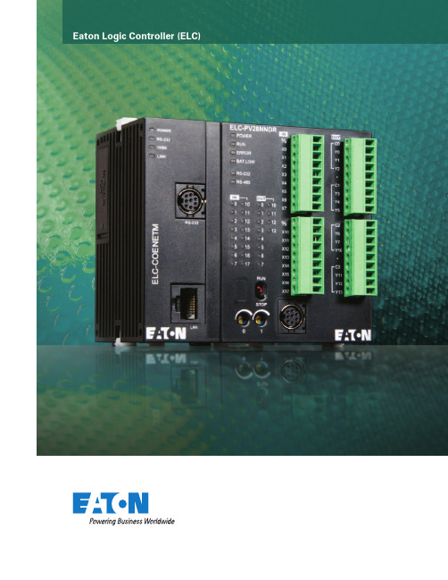
Eaton Logic Controller (ELC)The Eaton Logic Controller.Compact, modular, and ready tocommunicate. It’s the cost-effectivesolution to machine control.The right amount of I/O.Why pay for functionality you don’t need? Why be trapped with functionality you can’t scale to meet changing needs? Eaton is changing everything with the ELC.At less than half the size of most PLCs, the ELC is an ideal solution when space is at a premium and specialized I/O needs present themselves.Space saving. Cost saving.This space-saving design is as perfectly at home in asmall machine control station as it is in an MCC and other enclosed applications where space is critical. Reduced space also means smaller control cabinets and panels, or more capability in the same amount of space. However you look at it, the ELC means value.Half the size of most PLCs, the ELC puts the right amount of I/O right where you need it.ELC Controller and Expansion Modules.ELC Programming SoftwareProgram on your PC and download to the ELC through a serial cable or over Ethernet. Make online changes, monitor and remote control the run/stop operation. Software wizards simplify the programming process.eaton corporation Programmable Logic Controller 3Machine spaceis measured in inches.The ELC is measuredthe same way.eaton corporation Programmable Logic Controller 5ELC’s value added differences 5 controller styles: •PB Base Model— 14 I/O (8i/6o)Over 130 instructions provide all the power you need. Two serial ports for master/slave communications.•PC Clock/Calendar Model— 12 I/O (8i/4o)Same as the PB model, plus clock/calendar, twice theprogram steps, distributed I/O, and retentive data storage.•PA Analog Model— 10 I/O (6i/4o)Same as the PC model, plus embedded analog I/O.•PH High-Speed Model— 12 I/O (8i/4o)Same as the PC model, plus the ability to capture or output 100 kHz pulses.•PV Advanced Model— 28 I/O (16i/12o)Almost 10 times faster than the other ELC controllers, high speed I/O to 200 kHz, and additional advanced features. Add left side expansion modules for master communicationson networks such as Ethernet and DeviceNet ™.More Controller Features•High-speed pulse capture and high-speed pulse output on all controllers.•Broad selection of AC/DC in, relay/transistor and high current output modules.•Large selection of analog In/Out in various I/O counts per module.• 2 Modbus ®(ASCII / RTU) serial ports: 1 slave only, 1 master/slave.•Over 200 instructions to choose from: Floating point math, communications, 16- and 32-bit math, logical, blockmove, block compare, retentive data storage, conversion, time base from clock/calendar.ELC benefits solve applications:Size —large PLC features in a 1" package. Half the size of competitive offerings. ELC can retrofit more I/O in the same space or allow more costsavings by reducing cabinet size.Flexibility —ELC controllers expand from 10 to hundreds of I/O points. Expand with up to 16 modules (no more than 8 analog/specialty modules).•Add only the amount of I/O you need. Choose I/O counts as small as 2 points and as large as 16 points per module.•DIN-rail mounting lets you add as many modules as needed by snapping them into mating connectors.Large PLC Features —Multiple communications ports,distributed I/O capability, high speed counters, high speed pulse outputs, interrupts, timer resolution to 1ms, PIDs, plus much more.Software —ELCSoft programs in standard ladder or sequential function chart programming.•Display registers “in use” and modules attached to the ELC.•Monitor runtime applications and enter/modify register values.•Wizards aid programming of ELC Link for distributed I/O, standard communications, high speed counters,pulse outputs, positioning, interrupts, PIDs, and extension module setup.Communications —Connecting to networks is easy on Modbus ®, Modbus TCP , DeviceNet ™, and Profibus.No racks requiredA DIN-rail lets you add as many modules as desired. Just snap on, and slide into place. All connections are done automatically. Built-in displayAn integral LED display on some models provides user-assigned process monitoring, error messages, alarms, display counts and more.ELC Features and SpecificationsELC Controller Features and Specificationscontroller eLc-pB14nnDr/Dt eLc-pa10aaDr/Dt eLc-pc12nnar/Dr/Dt eLc-pH12nnDt eLc-pV28nnDr/Dt Dimensions WxHxD (mm) 25.2 x 90 x 60 37.4 x 90 x 60 70 x 90 x 60 Maximum I/O—Expandable up to 16 expansion modules (maximum of 8 analog/specialty modules)I/O Type—Embedded 14 (8 DI/6DO) 10 (4DI/2DO/2AI/2AO) 12 (8 DI/4 DO) 28 (16DI/12DO) DC In Sink/Source YesExecution Speed Basic instructions—2 µs minimum 0.24 µs minimum Program Language Instructions + Ladder Logic + SFCProgram Capacity (steps) 3792792015,872Data Memory Capacity (bits) 12804096Data Memory Capacity (words) 744500010,000 Index Registers 2816File Memory Capacity (words) None1600 Words 10,000 Words Retentive Storage YesCommands Basic/Advanced 32/107 32/168 32/193 Floating Point YesSFC Commands (steps) 1281024Timers Qty 128244 standard with additional timers for subroutine and retentive applicationsTimers Resolution1–100msCounters Qty 128 250 253High Speed Counters (See Note)Up to 4Up to 6Up to 8Up to 8Max High Speed Counting (See Note) 2 at 20 kHz 1 at 30 kHz 1 at 100 kHz 2 at 200 kHz Pulse Output 2 channels, 10 kHz Max 2 channels, 50 kHz Max 100 kHz 200 kHzPID YesMaster Control Loop 8 LoopsSubroutines 64 Subroutines 256 SubroutinesFor/Next Loops YesInterrupts 61522Real-time Clock / Calendar No Built-inPassword Security YesDiagnostic Relays YesDiagnostic Word Registers YesSpecialty Expansion Modules (Analog In/Analog Out/TC/RTD/PT) Up to a maximum of 8Serial Ports 2 Modbus (ASCII/RTU) 1=Slave (RS-232)/1=Master-Slave (RS-485)Remote I/O No With 16 other devices With 32 other devices Run Time Editing No YesRun / Stop Switch YesRemovable Terminal Strips YesSpecial Features —2, 7-Segment Displays 2 Potentiometers 2 PotentiometersHigh-speed, left side bus Note: High speed counter inputs can be used for different types of 32-bit counting, such as single-ended, single-phase two inputs, and quadrature.Therefore, all high speed counters may not be used at the same time. Please refer to the ELC Systems Manual, MN05003003E, for details.controller Module inputs outputs110 Vac 24 Vdcsink/sourceanalog relay24 Vdcsinking analogELC-PB14NNDR—8—6——ELC-PB14NNDT—8——6—ELC-PC12NNAR8——4——ELC-PC12NNDR—8—4——ELC-PC12NNDT—8——4—ELC-PA10AADR—422—2 ELC-PA10AADT—42—22 ELC-PH12NNDT—8——4—ELC-PV28NNDR—16—12——ELC-PV28NNDT—16——12—eaton corporation Programmable Logic Controller6ELC Expansion Module FeaturesDigital i/o Model power input Unit output Unitpoint type point typeDimensions WxHxD (mm) 25.2 x 90 x 60ELC-EX08NNAN24 Vdc 8110 Vac0—ELC-EX08NNDN8DC Sink or Source 0—ELC-EX08NNNR08Relay ELC-EX08NNNT08Transistor ELC-EX06NNNI06High Current Relay ELC-EX08NNDR44Relay ELC-EX16NNDR88ELC-EX08NNDT44Transistor ELC-EX16NNDT88analog i/o Model power input Unit output Unitpoint type point typeDimensions WxHxD (mm) 25.2 x 90 x 60ELC-AN02NANN24 Vdc 0—20~+20mA OV~+10VELC-AN04NANN04ELC-AN06AANN4–20mA~+20mA–10V~+10V 2ELC-AN04ANNN40—ELC-PT04ANNN4Platinum Temp.0ELC-TC04ANNN4Thermocouple0 Electrical SpecificationsInput Voltage Requirements ELC: 24 Vdc (–15%~+20%) (with DC input reverse polarity protection), Expansion Unit: supplied by the ELCPower Consumption Typically 3–6WInsulation Resistance>5 MΩ at 500 Vdc (Between all inputs/outputs and earth)Noise Immunity ESD: 8 kV Air Discharge EFT: Power Line 2 kV, Digital I/O: 1 kV, Analog & Communication I/O: 1 kV Damped-Oscillatory Wave: Power Line: 1 kV, Digital I/O: 1 kV RS: 26 MHz–1 GHz, 10 V/mTemperature Operation: 0ºC~55ºC (Temperature), 50~95% (Humidity), Pollution degree 2; Storage: –40ºC~70ºC (Temperature), 5~95% (Humidity)Vibration/ShockResistanceStandard: IEC1131-2, IEC 68-2-6 (TEST Fc)/IEC1131-2 & IEC 68-2-27 (TEST Ea)Certifications C-Tick, cULus, CE, Class I Div 2 Groups A, B, C, DELC Accessoriescatalog number DescriptionELC-PS0124 Watt, 1 Amp Power SupplyELC-PS0248 Watt, 2 Amp Power SupplyELC-HHP Hand-Held Programmer (includes cable)ELC-CBPCELC1Cable to connect a PC or ELC-GP unit to ELC, 1 meter with right angle connector (DB9 pin female to 8-pin DIN)ELC-CBPCELC3Cable to Connect a PC or ELC-GP unit to ELC, 3 meters (DB9 pin female to 8-pin DIN)ELC-CBPCGP3Cable to Connect a PC to an ELC-GP unit, 3 meters (DB9 pin female to DB9 pin female)ELC-GPXFERMOD Program transfer module for ELC-GP unitsELC-ACPGMXFR Program transfer module for ELC controllersELC-ACCOVER Plate mount for specialty modules, qty. 10ELCSTARTKIT1ELC Starter Kit (includes ECL-PA10AADT, ELC-PS01, ELC-GP04, ELC-CBPCELC3,ELC-CBPCGP3, ELCSoft, ELCSoft GP)ELC-COENETM10/100 Ethernet Module, need ELC-PV, ModbusTCP, P-P, for use with ELC-PV onlyELC-CODNETM DeviceNet Module, need ELC-PV, Scanner, Poll, CC, COS, BS, for use with ELC-PV onlyELC-COPBDP Profibus DP Slave ModuleELC-CODNET DeviceNet Slave ModuleELC-485APTR RS-485 Easy Connect Adapter, DB9, RJ-12, 2-Pin Connections to RS-485ELC-MC01Motion Control, 1 Axis Module (Up to 8 Modules per Controller)eaton corporation Programmable Logic Controller7Eaton Corporation Electrical Sector1111 Superior Ave. Cleveland, OH 44114United States877-ETN-CARE (877-386-2273) © 2010 Eaton CorporationAll Rights ReservedPrinted in USAPublication No. BR05003001E / MZ588 March 2010PowerChain Management is a registered trademark of Eaton Corporation.All other trademarks are property of theirrespective owners.Eaton’s Electrical Sectoris a global leader in power distribution, power quality, control and automation, and monitoring products. When combined with Eaton’s full-scale engineering services, these products provide customer-driven PowerChain™ solutions to serve the power system needs of the data center, industrial, institutional, public sector, utility, commercial, residential, IT, mission critical, alternative energy and OEM markets worldwide. PowerChain solutions help enterprises achieve sustainable and competitive advantages through proactive management of the power system as a strategic, integrated asset throughout its life cycle, resulting in enhanced safety, greater reliability and energy efficiency. For more information, visit /electrical.。

29Design and OperationEaton Automatic Control Systems (ACS) are specifical-ly designed to monitor and operate the backwashcleaning system of aton Automatic Strainers. They are simple to operate, reliable and easily maintained. The design allows field adjustments to suit the demands of the service conditions, ensuring effective cleaning with a minimum useof backwash fluid.Three basic systems,ACS-1, ACS-2 and ACS-3 are available.Optional designs to meet specificrequirements with special wiring arrangements, panel boxes (NE MA 7, 9), control valves, and air actuation among others, can be furnished.ACS-1 Standard Control System ComponentsThis system features a NEMA 4 rated (water and dust tight) panel box complete with adjustable timer, differ-ential pressure override, 10 amp control relay for back-wash valve activation, display lights to indicate Power On – Backwash Valve Open – and High Differential Pressure. A selector switch is also included to manual-ly control the backwash valve functions of Off or On-Auto. The panel also has contact terminals for a motor starter and an external alarm connection. The panel requires 110 VAC input and is CSA approved, UL approval is available as an option. The panel has a dif-ferential pressure switch and an electrically-actuated ball valve that controls the backwash function. With Model 596LPD for low pressure systems, an electrical-ly-operated butterfly valve is included to control the external source of cleaning water.ACS-2 Standard Control System ComponentsThis system has all of the features of the ACS-1 and includes a motor starter in addition to the other stan-dard equipment.ACS-3 Standard Control System ComponentsThis system has all of the features of the ASC-2 sys-tem and includes a 460V/120V dual voltage trans-former.MotorsAn electric motor and gear box are furnished as part of the strainer. The standard TE FC motor is 120/220V,Single phase 60 Hz, or 230/460V Three Phase 60 Hz,at customer option. Other motors are available.Modes of OperationBy operating the selector switch, the controls can be easily switched to either of two modes: automatic intermittent or continuous backwashing.The automatic intermittent mode is adjustable by set-ting the timer in the panel that controls the frequency of backwashing and the ˝open˝ time of the backwash valve. The settings will depend on the individual instal-lation. Predicting average times is difficult because conditions vary. Experience will dictate the optimal set-tings. Field adjustments should be made to suit the application.The differential pressure switch must also be set. Two PSID above the clean reading is the setting recom-mended. This switch will compensate for sudden high loadings by overriding the time cycle and initiating backwash should the differential pressure rise above the programmed setting. A secondary delay timer will continue the cleaning for 60 seconds beyond that point. The time delay can be varied from 1 to 150 sec-onds.The continuous backwashing mode is positive, efficient and practical where the backwashing fluid can be recycled to its source. It is also desirable, and some-times necessary, to use this mode when very high solid loadings are encountered.This mode is initiated by placing the backwash switch on the panel in the ˝on˝ position. Manual operation of the system can be controlled with this switch, opening or closing the backwash valve as desired. Returning it to ˝auto˝ will restore the intermittent cycling as set.In both the automatic intermittent and continuous backwashing modes the backwash arm continuously rotates at a low 2-4 RPM.Differential Pressure SwitchA diaphragm-type differential pressure switch is a standard component in all Control Systems. It provides protection for the strainer and element, initiating back-wash should a high differential pressure occur between timed cleaning intervals.Backwash ValveE lectrically actuated (115 VAC/60 Hz) ball valves are also standard in the Control Systems. Materials of con-struction are suitable for water service. Other materi-als, valve types and pneumatic actuation are optional.Backwash Valve Sizes。
Eaton 072899Eaton Moeller® series PKZ Trip indicator, 2 x 1 NC, Screw terminalsGeneral specificationsEaton Moeller® series PKZ Trip indicator 072899AGM2-01-PKZ0401508072899368 mm 90 mm 23 mm 0.035 kgCEIEC/EN 60947-4-1 CSA File No.: 165628 CSA-C22.2 No. 14 UL File No.: E36332 CSA Class No.: 3211-05 UL 508 CSAUL Category Control No.: NLRV ULProduct NameCatalog NumberModel Code EANProduct Length/Depth Product Height Product Width Product Weight Certifications3.5 AIs the panel builder's responsibility. The specifications for the switchgear must be observed.NoneMeets the product standard's requirements.Is the panel builder's responsibility. The specifications for the switchgear must be observed.Side mountingDoes not apply, since the entire switchgear needs to be evaluated.Meets the product standard's requirements.Is the panel builder's responsibility.55 °C50,000 Operations0 WIs the panel builder's responsibility.-25 °CDoes not apply, since the entire switchgear needs to be evaluated.Does not apply, since the entire switchgear needs to be Motor Starters in System xStart - brochureMotor-Protective Circuit-Breaker PKE - brochurePKE – Communication module Modbus RTUProduct Range Catalog Switching and protecting motorsDA-DC-00004246.pdfDA-DC-00004244.pdfDA-DC-00004601.pdfDA-DC-00004109.pdfDA-DC-00004245.pdfDA-DC-00004316.pdfDA-DC-00004108.pdfDA-DC-00004545.pdfeaton-motorstarters-auxiliary-contact-pkz-trip-indicator-characteristic-curve-004.epseaton-motorstarters-auxiliary-contact-pkz-trip-indicator-characteristic-curve-003.epsDA-DC-00004945.pdfDA-DC-00004912.pdfDA-DC-00004911.pdfDA-DC-00004935.pdfDA-DC-00004921.pdfDA-DC-00004885.pdfDA-DC-00004879.pdfDA-DC-00004878.pdfDA-DC-00004883.pdfDA-DC-00004917.pdfDA-DC-00004919.pdfDA-DC-00004937.pdfDA-DC-00004884.pdfDA-DC-00004886.pdfDA-DC-00004881.pdfDA-DC-00004961.pdfRated operational current for specified heat dissipation (In) 10.11 Short-circuit ratingLamp holder10.4 Clearances and creepage distances10.12 Electromagnetic compatibilityMounting method10.2.5 Lifting10.2.3.1 Verification of thermal stability of enclosures10.8 Connections for external conductorsAmbient operating temperature - maxLifespan, electricalStatic heat dissipation, non-current-dependent Pvs10.9.3 Impulse withstand voltageAmbient operating temperature - min10.6 Incorporation of switching devices and components 10.5 Protection against electric shock BrochuresCatalogsCertification reportsCharacteristic curve Declarations of conformityevaluated.440 V, Between auxiliary contacts and main contacts, According to EN 61140Motor protective circuit-breaker3.5 AScrew connectionThe device meets the requirements, provided the information in the instruction leaflet (IL) is observed.Does not apply, since the entire switchgear needs to be evaluated.Is the panel builder's responsibility.2Does not apply, since the entire switchgear needs to be evaluated.0.1 W2 A0.75 - 2.5 mm²5 A, 600 V AC, (UL/CSA)1 A, 250 V DC, (UL/CSA)Accessories1General trip indication (overload)Short-circuits indicated locally by means of a red indicator that DA-DC-00004920.pdfDA-DC-00004960.pdfDA-DC-00004891.pdfDA-DC-00004918.pdfDA-DC-00004953.pdfDA-DC-00004916.pdfDA-DC-00004887.pdfDA-DC-00004910.pdfDA-DC-00004915.pdfDA-DC-00004889.pdfDA-DC-00004890.pdfDA-DC-00004952.pdfDA-DC-00004888.pdfDA-DC-00004913.pdfDA-DC-00004892.pdfDA-DC-00004880.pdfDA-DC-00004950.pdfDA-DC-00004914.pdfeaton-manual-motor-starters-auxiliary-contact-pkz0-trip-indicator-dimensions.epseaton-manual-motor-starters-auxiliary-contact-pkz-trip-indicator-3d-drawing.epsDA-CE-ETN.AGM2-01-PKZ0IL03402030ZVideo Motor Protective Circuit Breaker PKEWIN-WIN with push-in technologyDA-CD-agm2DA-CS-agm2eaton-motorstarters-auxiliary-contact-pkz-trip-indicator-wiring-diagram-002.epsSafe isolationUsed withRated operational current (Ie) at AC-15, 220 V, 230 V, 240 V Electric connection type10.13 Mechanical function10.2.6 Mechanical impact10.9.4 Testing of enclosures made of insulating materialNumber of contacts (normally closed contacts)10.3 Degree of protection of assembliesHeat dissipation per pole, current-dependent PvidRated operational current (Ie) at AC-15, 380 V, 400 V, 415 V Terminal capacity (solid/flexible with ferrule)Switching capacity (auxiliary contacts, general use) Product categoryNumber of switches (fault signal)Indication DrawingseCAD model Installation instructions Installation videos mCAD modelWiring diagramscan be manually resetEquipment heat dissipation, current-dependent Pvid0 WHeat dissipation capacity Pdiss0 WRated operational current (Ie) at DC-13, 60 V1 ARated operational current (Ie)1 A at AC-15, 440 V 500 VShort-circuit protection rating without welding10 A gG/gL, Fuse, Auxiliary contacts10.2.3.2 Verification of resistance of insulating materials to normal heatMeets the product standard's requirements.10.2.3.3 Resist. of insul. mat. to abnormal heat/fire by internal elect. effectsMeets the product standard's requirements.Connection typeScrew connectionLifespan, mechanical10,000 OperationsRated operational current (Ie) at DC-13, 220 V, 230 V0.25 ATerminal capacity (solid/stranded AWG)18 - 1410.9.2 Power-frequency electric strengthIs the panel builder's responsibility.Control circuit reliability< 2 λ, < 1 failure at 100,000,000 Operations (at Uₑ = 24 V DC, Umin = 17 V, Imin = 5.4 mA)Overvoltage categoryIIIRated operational voltage (Ue) at DC - max250 VPollution degree310.7 Internal electrical circuits and connectionsIs the panel builder's responsibility.Eaton Corporation plc Eaton House30 Pembroke Road Dublin 4, Ireland © 2023 Eaton. All Rights Reserved. Eaton is a registered trademark.All other trademarks areproperty of their respectiveowners./socialmedia6000 V ACThe panel builder is responsible for the temperature rise calculation. Eaton will provide heat dissipation data for the devices.Meets the product standard's requirements.Meets the product standard's requirements.Meets the product standard's requirements.0Top mounting0.5 AA600, AC operated (UL/CSA) Q300, DC operated (UL/CSA)2 ARated impulse withstand voltage (Uimp)10.10 Temperature rise10.2.2 Corrosion resistance10.2.4 Resistance to ultra-violet (UV) radiation 10.2.7 InscriptionsNumber of contacts (normally open contacts)Model Rated operational current (Ie) at DC-13, 110 V Number of contacts (change-over contacts)Switching capacity (auxiliary contacts, pilot duty)Rated operational current (Ie) at DC-13, 24 V。
From the mountains to the valleys Intelligent automation solutions from Eaton enable efficient water supplyLocation:Remchingen, Germany Segment:Machine buildingChallenge:Two decentralized elevated tanks needed to be newly automated, and the existing line(longer than 1 km) needed to be maintained.Solution:A combination of an easy806 control relay with SmartWire-DT and a CoDeSys 3 XC-152 control system with SmartWire-DT as well as the XV-152 HMI panel with the Galileo visualization software. Switchgears (e.g. PKZ), DS7 soft starters and push-buttons from the RMQ Titan series are also installed. Results:Convenient and cost-efficient automation solution for the control of the water supply in Remchingen through the clever connection of the two decentralized elevated tanks to the central pumping station in the valley using the existing telephone line.“Time is the mostcrucial factor in our work.Thanks to SmartWire-DT,the simple installation ofautomation technologyhas managed to providean estimated time-saving of 30 percent inthis project.”Oliver Giesinger, ProservThe automationarchitecture of the water supplyin the Baden-Württembergcommunity of Remchingenurgently needed modernizing.The contract for this wasawarded to Proserv GmbHAutomatisierungstechnik.It opted for a complete solutionfrom Eaton with an easy806control relay linking twodecentralized elevated tanksvia easyNET to an XC-152control system with a sepa-rate HMI touch panel in thepumping station. In both casesSmartWire-DT was used as aconnection system inside theswitch cabinet.BackgroundThe modernization of the watersupply system in Remchingeninvolved replacing theautomation technology of twodecentralized elevated tanks,situated on a hill, andconnecting them to thetechnology of the pumpingstation in the valley, whichwas also to be replaced. Thecontract for this work wasawarded to Remchingen-based Proserv GmbHAutomatisierungstechnik(“Proserv”). In addition toclassic switchgear construction,the company also operates inthe fields of electricalengineering, E-CAD,automation with PLC andvisualization and handlescomplete projects.Proserv had previousexperience with switchingequipment and push-buttonsfrom Eaton, but this projectwas the first time that thecompany decided to useEaton’s range of controlsand its SmartWire-DTcommunication system.The decision to work withEaton on this project wasultimately made not onlybecause of the establishedgood business relationshipbetween the companies, butalso because the providedsolution was the only one tooffer the possibility of linkingthe three separate locationswith control technology at areasonable cost.ChallengeThe central challenge in theproject was that the twodecentralized elevated tanksneeded to be connected tothe pump station in the valley -while maintaining thecommunication lines, that wereover a kilometer long. Dueto the inaccessibility of theterrain and the length of theline, upgrading it would havebeen far too expensive. Assuch, conventional bus systemssuch as Profibus were not evenconsidered, as they wouldhave required a new line to beinstalled.Above all, the connection hadto operate absolutely reliably.In water supply, uninterruptedoperation is of the utmostimportance. In addition, themodernization was to facilitatethe operation of the systemand provide additional controland programming functions.Customer Success Story:Proserv GmbH Automatisierungstechnik Markets servedWater/WastewaterEatonEMEA Headquarters Route de la Longeraie 7 1110 Morges, Switzerland Eaton.eu© 2015 EatonAll Rights Reserved Publication No. CS083046EN November 2015Eaton is a registered trademark. All other trademarks are property of their respective owners.SolutionEaton’s easyNET network solves several challenges at once. Firstly, the technology meets the most important condition, namely that the existing telecontrol line could also be used for the new automation solution - an important cost factor. Dueto the particular installationin the mountainous area and the length of the line, Proserv and Eaton conducted their own functionality tests before commissioning to ensure that the communications securityof easyNET would always be ensured, even with cables not supplied by them and over such a distance.In addition, easyNET servesas an intermediary between two worlds. The system, based on the CAN network, enables an exchange of process and system data,and is capable of connecting eight network devices (e.g. controllers). It combines two types of network participants with different programming- namely ones from the easy-world (programming in the form of a circuit diagram) and controls from the IEC standard (programming according to IEC 1131). In Remchingen,the solution consists of the decentralized easy806 control relay for the elevated tanks and the XC-152 controller basedon CoDeSys 3 with a separate 10.4” XV-152 HMI touch panel in the pumping station located in the valley. The visualization of the HMI panel is achieved using Eaton’s Galileo software.“It was our first project witha control system based on CoDeSys. As an experienced automation technician, a four-hour foundation course from Eaton was enough for meto write the control program for the application. The pre-programmed functional blocks, which were delivered withthe control system, were very helpful here. It makes life a lot easier to not have to program everything manually and saves a considerable amount oftime in comparison to similar systems. Galileo was also new to me. But again, I foundthe programming simple,”explains Oliver Giesinger, oneof Proserv’s two managingdirectors.Further automationcomponents such asswitching devices andpush-buttons from the RMQTitan series are connectedto the XC-152 controller viaSmartWire-DT. Various diagnos-tic and status messages withreadout capability are madeavailable to the user throughthe starter combination (DS7soft starter and PKZ manualmotor starter). Individual deviceparameters can thus be readand (over)written. Various I/Omodules are also connectedwith SmartWire-DT to theeasy806 control relay. Whererequired, this modular structurecan be extended flexibly andwith a minimum of effort.“At first I was skeptical aboutSmartWire-DT, but the systemhas won me over. Mostlybecause of the unbelievableamount of time that it saves.It only took about an hour toinstall all of the SmartWirecomponents. An added bonuswas that SmartWire-DT keptwiring errors to a minimum andenabled further usefulfunctions that conventionallywould only be implementedin much more complex andexpensive systems,” continuesGiesinger.ResultsThe automation solution fromEaton, with the unique mixof simple, easy control relaysand individually programmableCoDeSys control systemswith a clear display, is bothcost-efficient and user-friendly.Costs were saved as a new linebetween the elevated tanksand the pumping station didnot have to be laid. Comparedwith conventional solutions,SmartWire-DT significantlyreduces the installation costsfor all automation technology.Furthermore, the startercombinations increase systemavailability by transmittingprocess-related data - e.g.motor current or switch setting- and Eaton’s communicationsystem saves the user fromtime-consuming troubleshoot-ing during commissioning andmaintenance.“Time is the most crucialfactor in our work. Thanksto SmartWire-DT, the simpleinstallation of automationtechnology has managed toprovide an estimated time-saving of 30 per cent in thisproject. Of course, the enduser also profited from this,as he had to pay us for lessman hours. I’m so impressedby SmartWire-DT that wewould also like to offer thissystem to other customers,”says Giesinger. “I can onlyrecommend Eaton, both for thequality of their products andwith regard to sales support.I work with all of the majormanufacturers of automationcomponents in Germany, butI’ve not received such goodsupport in 25 years.”The complex wiring of earlier days.The new streamlined automationusing modern technology fromEaton. It is clear which switchcabinet the plant manufacturerwould prefer to work on.Convenient for the user: Errormessages are sent by text messageand the system can be easily moni-tored and controlled via smartphoneor tablet.。
AAMA 501.5-07Test Method for ThermalCycling of Exterior Walls1.0SCOPE ........................................................................ .. (1)2.0 SUMMARY OF TEST METHOD (1)3.0 SIGNIFICANCE AND USE (1)4.0 REFERENCED STANDARDS (2)5.0APPARATUS .................................................................... .. (2)6.0 TEST SPECIMENS (3)7.0 SAFETY PRECAUTIONS (3)8.0PROCEDURE .................................................................... .. (3)9.0 PERFORMANCE REQUIREMENTS (4)10.0 TEST REPORT ....................................................................... .. 4AAMA. The Source of Performance Standards. Products Certification and Educational Programs for the Fenestration Industry.All AAMA documents may be ordered at our web site in the “Publications Store”. ©2007 American Architectural Manufacturers Association – These printed or electronic pages may NOT be reproduced, republished and distributed in any format without the express written consent of the American Architectural Manufacturers Association.This document was developed by representative members of AAMA asadvisory information and published as a public service. AAMA DISCLAIMS ALL WARRANTIES WITH REGARD TO THIS INFORMATION, INCLUDING ALLIMPLIED WARRANTIES OF MERCHANTABILITY AND FITNESS. IN NOEVENT SHALL AAMA BE LIABLE FOR ANY DAMAGES WHATSOEVER FROMTHE USE, APPLICATION OR ADAPTATION OF MATERIALS PUBLISHEDHEREIN. It is the sole responsibility of the user/purchaser to evaluate the accuracy, completeness or usefulness of any information, opinion, advice or other content published herein.AAMA 501.5-07ORIGINALLY PUBLISHED: 1998PRECEDING DOCUMENT: 501.5-98REVISED: 4/07PUBLISHED: 4/07American Architectural Manufacturers Association1827 Walden Office Square, Suite 550, Schaumburg, IL 60173PHONE (847) 303-5664 FAX (847) 303-5774EMAIL webmaster@ WEBSITE AAMA 501.5-07 Page 1 第一页1.0 SCOPE范围1.1 OBJECTIVES AND LIMITATIONS目标和局限性This test method provides a standard laboratory procedure for evaluation of thermal cycling effects on large exterior wall mock-ups, components and cladding. This test method utilizes convective hot air to achieve the exterior air temperature setpoint. The convective hot air exposure method usually provides a more severe test than infrared radiation methods because it elevates the exterior air temperature to levels that are not obtainable in real world conditions. This method is not intended for the evaluation of individual components such as windows and doors.本检测方法为大面积外墙样板、构件和围护热循环效果评估提供了标准的实验室检测程序。
Receive an enhanced3-year total warranty on your transmission and clutch when you bundle a Standard or FLEX Reman transmission with an Advantage Series or EverTough clutch and Eaton-approved lubricant. Standard warranties apply on individual purchases of the transmission and clutch.Linehaul, VocationalBuild your Reman Bundle inThree Easy StepsStep 1: Select a RemanT ransmissionAn Eaton Reman transmission,whether Standard or FLEX, ismade with Genuine Eaton partsand more new parts than anordinary rebuild. Every unit isperformance tested to ensureEaton quality specifications.Step 2: Select an AdvantageSeries or EverT ough ClutchEaton’s Advantage Seriesclutches are made for the longhaul. They feature a 50K milestandard lubrication interval forlinehaul applications and comewith a standard 3-year unlimitedwarranty. EverTough clutchesoffer a unique combination ofdurability and support in anaftermarket clutch. All EverToughclutches are 100% new andoffer a standard two-yearunlimited mile warranty, whichis upgraded to three yearswhen bundled.Step 3: Fill with Eaton-Approved LubricantEaton’s PS-386 SyntheticT ransmission Fluid is designedspecifically to optimize perfor-mance in Eaton transmissions.PS-386 improves fuel economy,reduces friction and gear wear,and prolongs the life of your trans-mission. Eaton-approved PS-386 isa necessary component in theReman Bundle Program.Eaton Reman™ Transmission+Eaton Advantage™ SeriesOR EverT ough™ Clutch+Eaton-Approved Lubricant= 3-Y ear/Unlim ited-MileTrans m ission AND Clutch Warranty*Replace with only genuineEaton parts for performance,durability and warrantyassurance.•Eliminate cross-referencemistakes and get the rightpart the first time, every time.•Maintain your warranty withgenuine components.•Choose Eaton, and getlegendary Roadranger supportfor More Time On The Road.*Applies to applications in the U.S.& Canada only. Please refer to theRoadranger Warranty Guide (TCWY0900)for the latest warranty time and mileageofferings.Notes:•Excludes Lightning transmissions(FRLO models).S U P P O R TB AC K ED B YFor spec’ing or service assistance, call 1-800-826-HELP (4357) or visit /roadranger.In Mexico, call 001-800-826-4357. Roadranger: Eaton and trusted partners providing the best products and services in the industry, ensuring more time on the road.EatonVehicle Group13100 E. Michigan Ave.Galesburg, MI 49053 USA800-826-HELP (4357)/roadranger© 2022 EatonAll Rights Reserved. Printed in USA.APSL0300 0122Y ou must register toreceive the RemanBundle warranty.Complete form TCWY0760 onsecond page and follow thesubmission instructions,or complete form online atNote: Features and specifications listed inthis document are subject to change withoutnotice and represent the maximum capa-bilities of the software and products with alloptions installed. Although every attempthas been made to ensure the accuracy ofinformation contained within, Eaton makesno representation about the completeness,correctness or accuracy and assumes noresponsibility for any errors or omissions.Features and functionality may vary dependingon selected options.Eaton, Fuller, Roadranger, Solo, UltraShift andFuller Advantage are registered trademarks ofEaton. All trademarks, logos and copyrightsare those of their respective owners.Factory Reman Bundle Warranty/Clutch Installation Kit Bundle Warranty Roadranger Warranty Registration Form TCWY0760Use this form to activate additional one year warranty on:• Heavy-duty Standard Reman/FLEX Reman, Reman Glider Kit and EverT ough clutch (Factory Reman Bundle Warranty)• EverT ough clutch (Clutch Installation Kit Bundle Warranty)Registration for additional warranty must be completed/submitted within one year of retail sale of bundled products.Factory Reman Bundle Warranty Instructions:1. Purchase of heavy-duty Reman transmission, Advantage/EverT ough clutch and Eaton-approved synthetic lubricant is required to activate additional 1-year warranty on above items.2. Please enclose proof of purchase or repair order listing transmission, clutch and lubricant along with this form to activate the warranty.3. Coverage confirmation will be sent by USPS mail.4. Advantage clutch, UltraShift, UtraShift PLUS and Lightning transmissions (FRLO models) are not included in this program.Clutch Installation Kit Bundle Warranty Instructions:1. Purchase of EverT ough clutch and clutch installation kit is required to activate additional 1-year warranty.2. Please enclose proof of purchase or repair order listingclutch and installation kit along with this form to activate the warranty.3. Coverage confirmation will be sent by USPS mail.4. All genuine clutch installation kits qualify.5. Advantage and UltraShift clutches are not included.Step 1: Enter owner/dealer informationOwner:____________________________________________________________Address:__________________________________________________________City:______________________________________________________________State/Prov:________________________ Postal Code:_____________________Phone:____________________________________________________________Email:____________________________________________________________Step 2: Enter vehicle/component informationOEM __________________________________ Date-In-Service ________________________ Current Odometer _______________________ MI KM Chassis VIN (17 characters): _______________________________________________________________________________________________________________T ransmission Model: ___________________________________________________ T ransmission Serial: ________________________________________________Clutch Part No.: ______________________________________________________ _ Clutch Installation Kit Part No.: ______________________________________Clutch Serial Number/Build Date ___________________________________________________________________________________________________________Lube Brand and picture of Eaton logo on container (or invoice): _______________________________________________________________________________Vehicle vocation (choose one only)Linehaul Standard Duty Construction Pickup and Delivery Fire ServicesRescue VehicleRecreation VehicleT ransit Coach School Bus Severe Duty Off Highway Agriculture Heavy Haul Logging MiningOil FieldRefuseY ard T ractorInterCity BusStep 3: Mail, fax or email this completed form with proof of purchase to:Mail:EatonFax: Email: c/o 360 Services, Inc.1-734-591-7899 ****************************** 275 E. 12 Mile Rd.Madison Heights, MI 48071Dealer Code:______________________________________________________Dealer:____________________________________________________________Dealer Contact:_____________________________________________________Dealer Contact Email:______________________________________________Address:__________________________________________________________City:______________________________________________________________State/Prov:________________________ Postal Code:_____________________Phone:____________________________________________________________S U P P O R TB AC K ED B Y© 2019 Eaton TCWY0760 0719Check here for email confirmation of warranty submission (please ensure you enter your email address above).。