HG8010设备操作手册
- 格式:doc
- 大小:551.00 KB
- 文档页数:4
目录页数1. 产品介绍.................................................................................1-1.简述……….……………………………………………….1-2.特性…...…………………………………………………... 1 1 12. 技术规格 (2)3. 使用前之注意事项……………………………….…………...3-1.拆开包装…………………..………………….…………...3-2.使用电源…………………...…………………..………….3-3.设备安装和操作………………………...………………...3-4.预备工作………………………………………………….. 3 3 3 4 44. 面板介绍 (5)5. 应用…………………………………………………………….5-1.灵敏度………..……………………………………………5-2.输入灵敏度特性………………...………………………...5-3.最大输入电压…………..………………………………...5-4.典型应用…………………………………………………..7 71011 116. 电路描述…………………..……………………………...…...6-1.工作原理……………………………..…………………....6-2.频率测量精度 (13)13147. 维护……………..……………………………………………..7-1.标准的校准方法………………….………………………7-2.清洁…..…………………………………………………... 18 18 181. 产品介绍1-1.简述GFC-8010H是一台高输入灵敏度20mVrms, 测量范围0.1Hz~120MHz的综合计频器.最新半导体技术的应用使仪器具备简洁,高性能,高分辨率和高稳定性的特点.1-2. 特性另外,此计频器还具备以下特性:●分辨率高达1μHz.●线性滤波器被密封在静电噪声区以扺制噪声的影响.●低通滤波器保证了低频的精确测量.●结构简洁,重量轻.●低功率消耗.●高质量的晶体保证了精确的频率测量.12. 技术规格灵敏度(rms) 10Hz~10MHz 10mV 10MHz~40MHz 20mV 40MHz~80MHz 35mV 80MHz~120MHz 50mV输入阻抗1MΩ35pF.最大输入电压150Vrms.耦合系统交流耦合时基晶振频率: 10MHz.老化率: ±1×10⁻⁶/月.温漂: 25℃±5℃±5×10-6.0℃~50℃±2×10⁻⁵. 精度1Hz + 1位数+时基误差计数容量8个十进制位显示系统数字发光二极管显示闸门时间0.1 s, 1 s, 10 s 开关可选最大分辨率1μHz (10Hz 范围,10s门时间) 0.1Hz (100MHz范围,10s门时间)工作温度范围0℃~40℃储存温度范围-10℃~+70℃功率消耗大约5W.电源要求100V, 120V/220V/230V±10%, 50/60Hz. 尺寸大约245(W) × 95(H) × 280(D) m/m.重量大约1.7kgs.附件操作手册……………………× 1 测试线GTL-101 …………..× 1233.使用前之注意事项 3-1. 拆开包装仪器在出厂前已被检测过.收到仪器后,请打开包装检查是否有运输过程中造成的损坏.若有,请及时与运货商或供货商联系.3-2. 使用电源仪器的使用电源可以是以下表格中任一种.请检查后面板上所标示的电源并替换相应的保险丝.警告: 为避免电击, 请务必将电源线保护接地端子接地.当使用电源改变,请按以下表格所示替换保险丝:使用电源 范围 保险丝 使用电源 范围保险丝100V 120V 90-110V 108-132V T160mA 250V 220V 230V 198-242V 207-253V T100mA 250V警告: 为避免人身伤害,换保险丝前请不要连接电源线.3-3.设备安装和操作请确保该仪器在适当的环境下使用.如果该仪器的使用未遵循规定,可能会造成对仪器的损坏.3-4.预备工作1)当阻抗是1MΩ,最大输入电压取决于频率和SENSITIVITY开关的位置,其相互关系如图6所示,此图表中的值须严格对应.初始时将SENSITIVITY开关打到1/10,如果此计频器不计数,将SENSITIVITY开关打到1/1范围并进行测量.此步骤可以降低损坏输入电路的危险性.2)选择交流电源100V, 120V, 220V, 或230V±10%.3)在0~40℃的环境温度下使用该计数器. 不要将仪器放在高温设备的顶上, 并保证仪器周围环境的通风.4)不要让水渗进仪器,也不要剧烈振动仪器.5)若仪器在特别嘈杂的环境中使用,在电源里加入噪声滤波器.6)测量低频时,按下低通滤波器开关,可以削弱高频成分,以防止可能出现错误触发.44. 面板介绍(1). Counter Input BNC 型接口(2). ATT, 1/1, 1/10 输入灵敏度(衰减)按钮.1/1 : 输入信号被直接连接到输入放大器.1/10: 输入信号衰减率为10.(3). LPF ON/OFF 低频测量时,将此键打到ON位置,插入输入信道一个100KHz低通滤波器.(4). FREQ/PRID 用此键选择频率测量或周期测量.(5). Gate TimeSelector用此按钮选择10s,1s或0.1s的门时间.(6). Power ON/OFF 电源开或关用此按钮.(7). Gate Time(LED) 显示设定的闸门时间10s,1s或0.1s(8). Over (LED) Over 指示灯亮表示一个或多个有效数字无法显示.(9). Displayed (LED) 频率值以8位数字显示.(10) Exponent andunits(LED) LED指示灯显示单位S和Hz,指示测量值指数如下:k=1000 M=1,000,000G=1,000,000,000 m=1/1000 μ=1/1,000,000 n=1/1,000,000,0005前面板图1. 前面板65. 应用5-1. 灵敏度灵敏度(或衰减器)开关对一般仪器的作用是保护输入电路和防止仪表超出量程.对计频器,灵敏度仍然起着这个重要的作用.迟滞一般发生在计数器的信号整形电路中.为了增强计频器对噪声的抵制,即使噪声低于迟滞(hysteresis),此电路也将不工作.这个信号整形电路是施密特电路(Schmitt Circuit),其作用图如下:图. 2 施密特电路作用图7根据图2,当输入电压为V+,输出为相对高的电压;当输入电压为V-, 输出为相对低的电压,电压差V H=(V+)-(V-)叫作迟滞电压. 若输入电压为图3中任一种情况,施密特电路将不工作,也无输出.图. 3 施密特电路不工作的状态从以上的描述中可以看出施密特电路是否工作取决于决定输入电压幅值大小的灵敏度.图4是合适选择灵敏度以防止错误计频的例子:(a)通过选择合适的灵敏度以正确对一个失真信号进行计频.当输入信号太大时,杂波也会被计频,所显示的实际上是未知频率的两倍.(b)若高频噪音信号迭加到未知信号并且输入施密特电路的电压过高,计频会发生错误.但选择合适的灵敏度可以获得正确的计频.8图. 4 9满足以下两点可以防止错误的计频:a)使噪音电压的峰峰值小于VH.b)当未知信号的峰峰值大于VH,测量时先将灵敏度设在1/10,然后再将其设在1/1以保护输入电路并避免错误的计频.5-2. 输入灵敏度(Sensitivity)特性这台仪器的输入灵敏度如图5所示.图. 5 输入灵敏度特性105-3. 最大输入电压最大输入电压(Input Voltage) V s频率特性如图6所示.图. 6. 最大输入电压-频率5-4. 典型应用下面是典型的几个应用:1).对于发射器或接受器的输出频率测量(输出功率在1W左右),仅仅需要将一圈带夹的导线接到天线以外几十厘米处,具体距离取决于输出的幅值.2).当进行振荡器阶段,乘法器阶段,及输出阶段的频率跟踪测量,则利用一个2-3圈的细线,将信号耦合到每一个线圈.(输入电容与多圈导线在谐振频率时可能引起谐振.)注意: 因为此产品有很高的灵敏度,当测试人员触到带夹线的红端(非接地端),感应现象可能会引起错误的计频.因此,11按以上方法进行测量时请把持住黑色夹和与之同轴的电缆.3).测量一般都可通过将带夹线黑的一端连到地,红的一端接到测试点进行.4).若电缆电容对测试电路有影响(当测量圈状的电路或高阻抗电路),测量前将一个高阻与带夹线串联插入.进行4)和5)的测量时,确保带夹线黑的一端连到地.如果可能的话,将此电缆接地到测试电路的地端.这个步骤可降低噪音的影响.除了(1-5), 利用计频器的特性还可进行其它不同的测量.126. 电路描述6-1. 工作原理为了更好地利用此频率计数器,充分理解电路是有用的.我们尽可能利用最新的集成电路技术以降低该产品的价格同时减小电路的复杂性,提高稳定性.假设输入信号到达10MHz~100MHz并输入到主板上标明的CHA.此信号首先由Q201~Q202放大.电路中的三级放大器标识为U202,是ECL逻辑电路.在线性误差范围内,每一级放大器在反馈之前的增益为5.Q203和Q204将ECL电平转变成TTL 电平.此信号直接被传送到计数器IC U301.IC U301提供此计频器的所有功能,通过LED显示结果.使用电源经变压器成为9V输入信号,U201调节此9V电压以纠正电路.当电源开关打在“on”位置,大约5.0V电压输入电路.136-2. 频率测量精度测量精度频率测量精度由以下两点决定:1)±1计频.2)时基精度.±1 计频的误差由数字表的特性和闸门信号(Gate Signal)与输入信号的相位差关系所决定.如图7,计频结果多1或少1取决于相位差.图. 7 ±1 计频误差14高精度测量振荡器的时基精度几乎完全由晶振特性所决定.时基规格如下: 振荡频率10MHz老化率1×10⁻⁶/月温漂5×10-6(25±5℃)±2×10-5 (校准环境温度0~40℃) 这台仪器中的晶振温度特性如图8所示.从中可看出温度系数最大为2×10⁻⁵.图. 8 晶振温度特性15晶振的温漂: 2×10⁻⁵(温度0~60℃) 25℃为参考. 选择0~60℃的温度范围是因为仪器内部的温升约20℃,而适合晶振的环境温度范围为:0~40℃.假设晶振的环境温度为25℃,频率为10MHz,则根据最大温漂和晶振频率,可能产生的误差为(10x106)x(2x10-5)=2x10²Hz.在实际应用中,以下两种情况会产生最糟的情况:1)在0℃的环境温度(Ambient temperature)下一打开仪器电源开关(Switch ON)即进行频率校准;在40℃的环境温度下打开仪器电源开关长时间后(Time elapsed after switch ON)进行测量.2)在40℃的环境温度下打开仪器电源开关长时间后进行校准;在0℃的环境温度下一打开仪器即进行测量.在这些最糟的情况下,保证精度4×10⁻⁵(校准温度:0~40℃) 即0.004%.图. 9 晶振上升特性范例16在实际应用中,上述最坏的情况几乎从未踫到过而且一直保持着高精度状态.图9为上升特性的一个范例,精度随着温度的变化而变化.如图所示,打开开关后50分钟,此仪器的晶振到达热平衡状态.发货前,此仪器在25℃的环境下校准了60分钟.如果仪器在打开开关1小时后开始工作且是在20~30℃的环境下校准,则即使用最糟的晶振也可保证精度5x10-6.5x10-6(25±5℃)用百分比表示为0.0005%.老化率1×10⁻⁶/月表示在恒定常温下一月后,变化为0.0001%.177.维护以下指示步骤仅可由合格人员执行﹒为避免电击﹐请不要进行操作手册上未指明的操作.7-1.校准的标准方法50分钟的预热后,将一标准的或精度高达1x10-7的STD OUT信号输入计频器.调整调节器SVC301以显示10.000000MHz.经过这个步骤可能会获得超过1x10⁻⁷的精度.用一个螺丝起子(非铁头)来调整调节器.7-2.清洁清洁仪器时﹐请用沾有水和温和溶剂的软布﹒不要将清洁剂直接喷到仪器上﹐以防止其渗透到外壳内造成损坏﹒不要用含有汽油﹐苯﹐甲苯﹐二甲苯﹐丙酮等相似的溶剂﹒不要将研磨剂用于仪器的任何部分﹒18。


ZTE 8010 Quick Start GuideFCC ID:SRQ-ZTE8010LEGAL INFORMATIONCopyright © 2020 ZTE CORPORATION.All rights reserved.No part of this publication may be quoted, reproduced, translated or used in any form or by any means, electronic or mechanical, including photocopying and microfilm, without the prior written permission of ZTE Corporation.NoticeZTE Corporation reserves the right to make modifications on print errors or update specifications in this guide without prior notice.We offer self-service for our smart terminal device users. Please visit the ZTE official website (at www.ztedevices.mx) for more information on self-service and supported product models. Information on the website takes precedence.Visit https://ztedevices.mx/soporte/ to download the user manual.DisclaimerZTE Corporation expressly disclaims any liability for faults and damages caused by unauthorized modifications of the software.Images and screenshots used in this guide may differ from the actual product. Content in this guide may differ from the actual product or software.TrademarksZTE and the ZTE logos are trademarks of ZTE Corporation. Android™ is a trademark of Google LLC.The Bluetooth®word mark and logos are registeredtrademarks owned by the Bluetooth SIG, Inc. and any use of such marks by ZTE Corporation is under license.microSDXC Logo is a trademark of SD-3C, LLC.For DTS patents, see . Manufactured under license from DTS Licensing Limited. DTS, the Symbol, & DTS and the Symboltogether are registered trademarks or trademarks of DTS, Inc. in the United States and/or other countries. © DTS, Inc. All Rights Reserved.Other trademarks and trade names are those of their respective owners.Version No.: R1.0Edition Time : April 22, 2020 ManualNo.:Getting to Know Your PhoneFront camera Touch screenEarpiece Volume key Powerkey/Fingerpri nt sensorCharging/USB Type-C jackHeadset jack Back camerasand flashSpeaker Indicator light nano-SIM/ microSDXC card trayProximity & light sensorSetting Up Your PhoneThe nano-SIM card can be installed or removed while the phone is turned on.WARNING!To avoid damage to the phone, do not use any other kind of SIM cards, or any non-standard nano-SIM card cut from a SIM card. Y ou can get a standard nano-SIM card from your service provider.1.Insert the tip of the tray eject tool into the hole on thecard tray.CAUTION:Never replace the included tray eject tool with sharp objects. Ensure that the tray eject tool is perpendicular to the hole. Otherwise, the phone may be damaged.2.Pull out the card tray and place the nano-SIM card andthe microSDXC card (optional) on the tray, as shown.Carefully slide the tray back into place.microSDXCcardnano-SIMcardCharging the PhoneYour phone’s battery should have enough power for the phone to turn on, find a signal, and make a few calls. Y ou should fully charge the battery as soon as possible. WARNING!Use only ZTE-approved chargers and USB Type-C cables. The use of unapproved accessories could damage your phone or cause the battery to explode.WARNING!Do not remove the back cover. The battery is not removable. Removal may cause fire or explosion.1.Connect the adapter to the charging jack.2.Connect the charger to a standard AC power outlet.3.Disconnect the charger when the battery is fullycharged.If the battery is extremely low, you may be unable to poweron the phone even when it is being charged. In this case, try again after charging the phone for at least 20 minutes. Contact the customer service if you still cannot power on the phone after prolonged charging.Powering On/Off Your PhoneMake sure the battery is charged before powering on. •Press and hold the Power key to turn on your phone. •To power off, press and hold the Power key to open the options menu, and touch >.NOTE:If the screen freezes or takes too long to respond, try pressing and holding the Power keyfor about 10seconds to restart thephone.FM RadioScanning for Channels1.Plug in a wired headset and open FM Radio.2.Touch > Scan. Y our phone scans for all availablechannels and saves them to the All channels list. Listening to FM Radio1.Open FM Radio while the headset is connected.2.Touch > All channels and select a channel.You can also drag the red line along the frequency panel ortouch or to switch to other channels, or touch orto adjust the current channel frequency.NOTES:•Touch to add the channel to favorites. •Touch to listen to the radio through the phone speaker.•The FM radio feature does not require an Internet connection.Product Safety InformationDon’t make or receive phone calls while driving. Never text while driving.Keep your phone at least 10 mm away from your body while making calls.Small parts may cause choking.Your phone can produce a loud sound.To prevent possible hearing damage, do not listen at high volume levels for long periods. Exercise caution when holding your phone near your ear while the loudspeaker is in use.Avoid contact with anything magnetic.Keep away from pacemakers and other electronic medical devices.Turn off when asked to in hospitals and medical facilities.Turn off when told to on aircraft and at airports.Turn off when near explosive materials or liquids.Don’t use at gas stations.Your phone may produce a bright or flashing light.Don’t dispose of your phone in fire.Avoid extreme temperatures.Avoid contact with liquids. Keep your phone dry.Do not attempt to disassemble your phone.Only use approved accessories.For pluggable equipment, the socket-outlet shall be installed near the equipment and shall be easily accessible.Don’t rely on your phone as a primary device for emergency communications.FCC RF Exposure Information (SAR)This phone is designed and manufactured not to exceed the emission limits for exposure to radio frequency (RF) energy set by the Federal Communications Commission of the United States.During SAR testing, this device was set to transmit at its highest certified power level in all tested frequency bands, and placed in positions that simulate RF exposure in usage against the head with no separation, and near the body with the separation of 10 mm. Although the SAR is determined at the highest certified power level, the actual SAR level of the device while operating can be well below the maximum value. This is because the phone is designed to operate at multiple power levels so as to use only the power required to reach the network. In general, the closer you are to a wireless base station antenna, the lower the power output.The exposure standard for wireless devices employing a unit of measurement is known as the Specific Absorption Rate, or SAR. The SAR limit set by the FCC is 1.6 W/kg. This device is complied with SAR for generalpopulation/uncontrolled exposure limits in ANSI/IEEE C95.1-1992 and had been tested in accordance with the measurement methods and procedures specified in IEEE1528.The FCC has granted an Equipment Authorization for this model phone with all reported SAR levels evaluated as in compliance with the FCC RF exposure guidelines. SARinformation on this model phone is on file with the FCC andcan be found under the Display Grant section of/oet/ea/fccid after searching on FCC ID: XXXXXXX. The FCC ID also can be found on the device when you open Settings > About phone > FCC ID.For this device, the highest reported SAR value for usage against the head is XXX W/kg, and for usage near the body is XXX W/kg.While there may be differences between the SAR levels of various phones and at various positions, they all meet the government requirements.SAR compliance for body-worn operation is based on a separation distance of 10 mm between the unit and the human body. Carry this device at least 10 mm away from your body to ensure RF exposure level compliant or lower to the reported level. To support body-worn operation, choose the belt clips or holsters, which do not contain metallic components, to maintain a separation of 10 mm between this device and your body.RF exposure compliance with any body-worn accessory, which contains metal, was not tested and certified, and using such body-worn accessory should be avoided.11。
目录页数1. 产品介绍.................................................................................1-1.简述……….……………………………………………….1-2.特性…...…………………………………………………...1 1 12. 技术规格 (2)3. 使用前之注意事项……………………………….…………...3-1.拆开包装…………………..………………….…………...3-2.使用电源…………………...…………………..………….3-3.设备安装和操作………………………...………………...3-4.预备工作…………………………………………………..3 3 3 4 44. 面板介绍 (5)5. 应用…………………………………………………………….5-1.灵敏度………..……………………………………………5-2.输入灵敏度特性………………...………………………...5-3.最大输入电压…………..………………………………...5-4.典型应用…………………………………………………..7 7 10 11 116. 电路描述…………………..……………………………...…...6-1.工作原理……………………………..…………………....6-2.频率测量精度……………………….…………………….13 13 147. 维护……………..……………………………………………..7-1.标准的校准方法………………….………………………7-2.清洁 (18)181811. 产品介绍1-1.简述GFC-8010H是一台高输入灵敏度20mVrms, 测量范围0.1Hz~120MHz的综合计频器.最新半导体技术的应用使仪器具备简洁,高性能,高分辨率和高稳定性的特点.1-2. 特性另外,此计频器还具备以下特性:●分辨率高达1μHz.●线性滤波器被密封在静电噪声区以扺制噪声的影响.●低通滤波器保证了低频的精确测量.●结构简洁,重量轻.●低功率消耗.●高质量的晶体保证了精确的频率测量.2 2. 技术规格 灵敏度 (rms) 10Hz~10MHz 10mV 10MHz~40MHz 20mV 40MHz~80MHz 35mV 80MHz~120MHz 50mV 输入阻抗1M Ω 35pF. 最大输入电压 150Vrms. 耦合系统 交流耦合时基晶振频率: 10MHz. 老化率: ±1×10⁻⁶/月.温漂: 25℃±5℃ ±5×10⁻⁶. 0℃~50℃ ±2×10⁻⁵. 精度1Hz + 1位数 +时基误差 计数容量 8个 十进制位显示系统 数字发光二极管显示 闸门时间 0.1 s, 1 s, 10 s 开关可选最大分辨率 1μHz (10Hz 范围,10s 门时间) 0.1Hz (100MHz 范围,10s 门时间) 工作温度范围 0℃~40℃储存温度范围-10℃~+70℃功率消耗 大约 5W.电源要求 100V, 120V/220V/230V ±10%, 50/60Hz. 尺寸 大约245(W) × 95(H) × 280(D) m/m. 重量 大约1.7kgs.附件 操作手册……………………× 1 测试线 GTL-101 …………..× 133.使用前之注意事项 3-1. 拆开包装仪器在出厂前已被检测过.收到仪器后,请打开包装检查是否有运输过程中造成的损坏.若有,请及时与运货商或供货商联系.3-2. 使用电源仪器的使用电源可以是以下表格中任一种.请检查后面板上所标示的电源并替换相应的保险丝.警告: 为避免电击, 请务必将电源线保护接地端子接地.当使用电源改变,请按以下表格所示替换保险丝:使用电源范围保险丝使用电源范围保险丝100V 120V 90-110V 108-132V T160mA 250V 220V 230V 198-242V 207-253V T100mA 250V警告: 为避免人身伤害,换保险丝前请不要连接电源线.4 3-3.设备安装和操作请确保该仪器在适当的环境下使用.如果该仪器的使用未遵循规定,可能会造成对仪器的损坏.3-4.预备工作1) 当阻抗是1M Ω,最大输入电压取决于频率和SENSITIVITY 开关的位置,其相互关系如图6所示,此图表中的值须严格对应.初始时将SENSITIVITY 开关打到1/10,如果此计频器不计数,将SENSITIVITY 开关打到1/1范围并进行测量.此步骤可以降低损坏输入电路的危险性. 2) 选择交流电源 100V, 120V, 220V, 或 230V ±10%.3) 在0~40℃的环境温度下使用该计数器. 不要将仪器放在高温设备的顶上, 并保证仪器周围环境的通风. 4) 不要让水渗进仪器,也不要剧烈振动仪器.5) 若仪器在特别嘈杂的环境中使用,在电源里加入噪声滤波器. 6) 测量低频时,按下低通滤波器开关,可以削弱高频成分,以防止可能出现错误触发.54. 面板介绍(1).Counter InputBNC 型接口(2).ATT, 1/1, 1/10 输入灵敏度(衰减)按钮.1/1 : 输入信号被直接连接到输入放大器. 1/10: 输入信号衰减率为10.(3).LPF ON/OFF 低频测量时,将此键打到ON 位置,插入输入信道一个100KHz 低通滤波器.(4).FREQ/PRID 用此键选择频率测量或周期测量.(5).Gate Time Selector 用此按钮选择10s,1s 或0.1s 的门时间.(6).Power ON/OFF 电源开或关用此按钮.(7).Gate Time(LED)显示设置的闸门时间10s,1s 或0.1s(8).Over (LED) Over 指示灯亮表示一个或多个有效数字无法显示.(9).Displayed (LED)频率值以8位数字显示.(10)Exponent and units (LED) LED 指示灯显示单位S 和Hz,指示测量值指数如下: k=1000 M=1,000,000G=1,000,000,000 m=1/1000 μ=1/1,000,000 n=1/1,000,000,0006 前面板图1. 前面板75. 应用 5-1. 灵敏度灵敏度 (或衰减器)开关对一般仪器的作用是保护输入电路和防止仪表超出量程.对计频器,灵敏度仍然起着这个重要的作用.迟滞一般发生在计数器的信号整形电路中.为了增强计频器对噪声的抵制,即使噪声低于迟滞(hysteresis),此电路也将不工作.这个信号整形电路是施密特电路(Schmitt Circuit),其作用图如下:图. 2 施密特电路作用图8 根据图2,当输入电压为V+,输出为相对高的电压;当输入电压为V -, 输出为相对低的电压,电压差V H =(V +)-(V -)叫作迟滞电压. 若输入电压为图3中任一种情况,施密特电路将不工作,也无输出.图. 3 施密特电路不工作的状态从以上的描述中可以看出施密特电路是否工作取决于决定输入电压幅值大小的灵敏度.图4是合适选择灵敏度以防止错误计频的例子:(a) 通过选择合适的灵敏度以正确对一个失真信号进行计频. 当输入信号太大时,杂波也会被计频,所显示的实际上是未知频率的两倍.(b) 若高频噪音信号迭加到未知信号并且输入施密特电路的电 压过高,计频会发生错误.但选择合适的灵敏度可以获得正确的计频.9图. 410满足以下两点可以防止错误的计频: a) 使噪音电压的峰峰值小于VH.b) 当未知信号的峰峰值大于VH,测量时先将灵敏度设在1/10, 然后再将其设在1/1以保护输入电路并避免错误的计频.5-2. 输入灵敏度(Sensitivity)特性这台仪器的输入灵敏度如图5所示.图. 5 输入灵敏度特性115-3. 最大输入电压最大输入电压(Input Voltage) V s 频率特性如图6所示.图. 6. 最大输入电压-频率5-4. 典型应用下面是典型的几个应用:1).对于发射器或接受器的输出频率测量(输出功率在1W 左右),仅仅需要将一圈带夹的导线接到天线以外几十厘米处,具体距离取决于输出的幅值.2).当进行振荡器阶段,乘法器阶段,及输出阶段的频率跟踪测量,则利用一个2-3圈的细线,将信号耦合到每一个线圈.(输入电容与多圈导线在谐振频率时可能引起谐振.)注意: 因为此产品有很高的灵敏度,当测试人员触到带夹线的 红端(非接地端),感应现象可能会引起错误的计频.因此,12按以上方法进行测量时请把持住黑色夹和与之同轴的电缆.3).测量一般都可通过将带夹线黑的一端连到地,红的一端接到测试点进行.4).若电缆电容对测试电路有影响(当测量圈状的电路或高阻抗电路),测量前将一个高阻与带夹线串联插入.进行4)和5)的测量时,确保带夹线黑的一端连到地.如果可能的话,将此电缆接地到测试电路的地端.这个步骤可降低噪音的影响.除了(1-5), 利用计频器的特性还可进行其它不同的测量.136. 电路描述 6-1. 工作原理为了更好地利用此频率计数器,充分理解电路是有用的.我们尽可能利用最新的集成电路技术以降低该产品的价格同时减小电路的复杂性,提高稳定性.假设输入信号到达10MHz~100MHz 并输入到主板上标明的CHA.此信号首先由Q201~Q202放大.电路中的三级放大器标识为U202,是ECL 逻辑电路.在线性误差范围内,每一级放大器在反馈之前的增益为5.Q203和Q204将ECL 电平转变成TTL 电平.此信号直接被传送到计数器IC U301.IC U301提供此计频器的所有功能,通过LED 显示结果.使用电源经变压器成为9V 输入信号,U201调节此9V 电压以纠正电路.当电源开关打在“on”位置,大约5.0V 电压输入电路.14 6-2. 频率测量精度测量精度频率测量精度由以下两点决定: 1) ±1计频. 2) 时基精度.±1 计频的误差由数字表的特性和闸门信号(Gate Signal)与输入信号的相位差关系所决定.如图7,计频结果多1或少1取决于相位差.图. 7 ±1 计频误差15高精度测量振荡器的时基精度几乎完全由晶振特性所决定.时基规格如下: 振荡频率 10MHz 老化率 1×10⁻⁶/月温漂 5×10⁻⁶(25±5℃) ±2×10⁻⁵ (校准环境温度0~40℃) 这台仪器中的晶振温度特性如图8所示.从中可看出温度系数最大为2×10⁻⁵.图. 8 晶振温度特性16 晶振的温漂: 2×10⁻⁵ (温度0~60℃) 25℃ 为参考. 选择0~60℃的温度范围是因为仪器内部的温升约20℃,而适合晶振的环境温度范围为:0~40℃.假设晶振的环境温度为25℃,频率为10MHz,则根据最大温漂和晶振频率,可能产生的误差为(10x106)x(2x10-5)=2x10²Hz.在实际应用中,以下两种情况会产生最糟的情况:1) 在0℃的环境温度(Ambient temperature)下一打开仪器电源开关(Switch ON)即进行频率校准;在40℃的环境温度下打开仪器电源开关长时间后(Time elapsed after switch ON)进行测量.2) 在40℃的环境温度下打开仪器电源开关长时间后进行校准;在0℃ 的环境温度下一打开仪器即进行测量.在这些最糟的情况下,保证精度 4×10⁻⁵ (校准温度:0~40℃) 即0.004%.图. 9 晶振上升特性范例17在实际应用中,上述最坏的情况几乎从未踫到过而且一直保持着高精度状态.图9为上升特性的一个范例,精度随着温度的变化而变化.如图所示,打开开关后50分钟,此仪器的晶振到达热平衡状态.发货前,此仪器在25℃的环境下校准了60分钟.如果仪器在打开开关1小时后开始工作且是在20~30℃的环境下校准,则即使用最糟的晶振也可保证精度5x10-6.5x10-6 (25±5℃)用百分比表示为0.0005%.老化率1×10⁻⁶/月表示在恒定常温下一月后,变化为0.0001%.计频器GFC-8010H 操作手冊7.维护以下指示步骤仅可由合格人员执行﹒为避免电击﹐请不要进行操作手册上未指明的操作.7-1.校准的标准方法50分钟的预热后,将一标准的或精度高达1x10⁻⁷的STD OUT信号输入计频器.调整调节器SVC301以显示10.000000MHz.经过这个步骤可能会获得超过1x10⁻⁷的精度.用一个螺丝起子(非铁头)来调整调节器.7-2.清洁清洁仪器时﹐请用沾有水和温和溶剂的软布﹒不要将清洁剂直接喷到仪器上﹐以防止其渗透到外壳内造成损坏﹒不要用含有汽油﹐苯﹐甲苯﹐二甲苯﹐丙酮等相似的溶剂﹒不要将研磨剂用于仪器的任何部分﹒18。
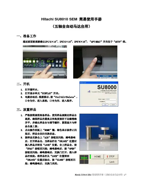
Hitachi SU8010 SEM 简易使用手册(五轴全自动马达台用)一、准备工作通过前面板观察确认IP1>2×10⁻⁷,IP2>2×10⁻⁶,IP3>5×10⁻⁵;“APT HEAT”开关位于“AUTO”档。
二、开机1.打开循环水。
2.打开显示单元“DISPLAY”开关。
3.电脑启动后,根据提示,按“Ctrl+Alt+Delete”,口令为空,进入系统;口令为空,进入程序。
三、放置样品1.严格按照规范制备样品,使用样品规限定样品台高度。
确保样品的最高点和高度规的下边缘精确齐平,并确认样品台与调节螺杆、紧固盘片与样品台座上紧。
2.点击操作面板上“HOME”键,绿色显示条停止闪烁后,样品台回归交换状态。
3.按样品交换仓上“AIR”按钮至闪烁;蜂鸣器响后,打开样品仓,当样品杆在“UNLOCK”位置时插入样品并转至“LOCK”位置;合上样品仓,按“EVAC”按钮至闪烁;蜂鸣器响后,按“OPEN”按钮至闪烁;蜂鸣器响后,交换门打开,推入样品杆到底;将样品杆从“LOCK”位置转回“UNLOCK”位置后抽出,按“CLOSE”按钮至闪烁;蜂鸣器响后,交换门关闭。
4.跳出样品台大小高度确认对话框,点击“OK”确认。
四、样品观察1.点击高压显示窗口,打开高压控制对话框,选择强度2,点击“Flashing”,点击“Excute”,执行Flashing。
记录下Flashing后的发射电流Ie和刚加高压后显示的引出电压Vext。
2.根据不同的样品以及观察需要,在高压控制对话框Vacc下拉列表中选择合适的加速电压;在SetIe to下拉列表中选择合适的发射电流;点击“ON”加高压。
3.观察过程中,根据实际需要,可在操作面板“SEM”菜单“SIGNAL SELECT”选区中,选择所要接收的信号“SE”(二次电子)、“LA-BSE”(低角背散射电子)、“HA-BSE”(高角背散射电子)或“SE(L)”(下探头二次电子);并选择探头“U”(上探头)或“L”(下探头);当选有BSE信号时,选择“SE Suppress”值“0-100”来控制SE信号和BSE信号的比例。
LED 指示灯8010 系列使用说明书其他语种 ENFRITESRUNLDKSEFIPTGRPLCZSKHUSLROBGLVLTEECHKRCN –保存以备将来使用!–内容目录2LED 指示灯8010 系列内容目录1总体信息...............................................................................................................31.1制造商..................................................................................................................31.2关于本使用说明书................................................................................................31.3其他文档...............................................................................................................31.4标准和规定的符合性.............................................................................................32符号说明...............................................................................................................42.1本使用说明书中的符号.........................................................................................42.2设备上的符号.......................................................................................................43安全......................................................................................................................53.1设计用途...............................................................................................................53.2人员资格...............................................................................................................53.3残余风险...............................................................................................................64运输和仓储...........................................................................................................75安装与装配...........................................................................................................75.1安装/拆卸............................................................................................................75.2装配......................................................................................................................76调试......................................................................................................................87运行......................................................................................................................88维护、保养、修理................................................................................................98.1维护......................................................................................................................98.2保养......................................................................................................................98.3修理......................................................................................................................99退回......................................................................................................................910清洁......................................................................................................................911废弃物处置.........................................................................................................1012配件和备件.........................................................................................................1013附录A................................................................................................................1013.1技术数据.............................................................................................................1014附录B................................................................................................................1314.1尺寸信息/固定尺寸 (13)301668 / 80106223002022-01-26·BA00·III·zh·02总体信息3LED 指示灯8010 系列1总体信息1.1制造商1.2关于本使用说明书▶在使用前必须认真阅读本使用说明书、尤其是安全提示。


深圳市嘉昱机电有限公司APS8010伺服驱动器产品使用说明书深圳市嘉昱机电有限公司2020.12目录1.产品简介 (3)1.1.功能介绍 (3)1.2.规格参数 (3)2.安装接线 (4)2.1.安装尺寸图 (4)2.2.电机尺寸图 (4)2.3.电气接线 (5)3.软件功能说明 (8)3.1.概述 (8)3.2.闸机功能 (8)3.3.系统框架 (9)3.4.拨码开关设定 (9)3.5.闸机指令 (10)3.6.闸机状态 (10)3.7.闸机功能说明 (10)4.显示与按键 (17)4.1.按键板概述 (17)4.2.菜单概述 (18)4.3.参数监控(d-) (18)4.4.参数设置(P-) (20)4.5.辅助功能(A-) (21)5.全部参数 (23)5.1.参数分组一览表 (23)5.2.参数总表 (23)5.3.闸机应用参数表介绍 (31)6.通信协议 (33)6.1.串口通信协议格式 (33)6.2.闸机应用举例 (36)7.CAN通信协议 (38)7.1.通信协议格式 (38)7.2.闸机应用举例 (39)7.3.IO设置应用 (41)8.程序更新 (45)8.1.准备工作 (45)8.2.升级步骤 (45)8.3.注意事项 (46)9.故障诊断 (47)9.1.故障信息 (47)9.2.常见问题 (48)1.产品简介APS8010系列伺服驱动器,为嘉昱机电面向高性能应用场景推出的一款伺服驱动产品,以60mm的超窄外形设计,搭载自主研发的PMSM+矢量控制的伺服控制技术,集成业界领先的通道机芯控制逻辑,可应用于机场、高铁、地铁等人行通道闸机设备。
1.1.功能介绍适配低压直流伺服电机,标准为增量式编码器反馈接口;集成业界领先的通道机芯控制逻辑,实时检测机芯运动状态,满足安全通行的要求;针对暴力闯闸等使用场景,内部设计有专用电路保障驱动器和电源的稳定工作。
支持RS232、RS485、CAN等多种通讯方式,提供Modbus通讯协议,可对接通道控制器;配套有数码按键盒、液晶按键盒等配套调试工具;提供MagicServo伺服调试上位机;1.2.规格参数输入电压DC24~80V额定/峰值电流10A/30A编码器反馈增量式带霍尔差分输入通讯接口RS232/RS485/CAN数字输入输出8进4出,光耦隔离专用接口2路功率输出硬件保护欠压、过压、过流、过温工作环境温度-20℃~55℃工作环境湿度≤95%(无凝结)待机功耗 2.5W/24V,5W/48V2.安装接线2.1.安装尺寸图2.2.电机尺寸图请查阅附录。
配置指导目录目录TMG8010上机指导书 (1)1.1组网介绍 (1)1.2配置步骤 (3)1.2.1配置前的检查 (3)1.2.2基本配置 (3)1.2.3设备配置 (3)1.2.4接口与IP协议配置 (5)1.2.5信令数据配置 (5)1.2.6 MGCP设备配置 (6)1.2.7其他IPP数据配置 (6)1.2.8配置后的检查 (7)TMG8010上机指导书1.1组网介绍本次培训上机环境中只有TMG8010,大家注重命令配置方法即可。
登陆方法:telnet 10.11.37.142,口令:tmg8010此环境因为没有和softx3000对接,因此不能联调,上机的目的只是达到熟悉命令和配置即可。
TMG8010的硬件配置是7、8号槽位上配置SMB板。
6、9号槽位上配置了HRB板。
0号槽位上配置VSP板,使用0和1号PCM端口。
SG做为逻辑实体与MG共处一个物理实体内。
TMG数据规划如表12-1所示:表12-1TMG8010数据规划表注意:上述数据中需要和对接交换机协商的数据有:1、对接交换机信令方式:ISUP、TUP还是PRA2、信令所承载哪一时隙:16时隙还是在哪一时隙上述数据中需要和SOFTX3000 MGC协商的数据有:1、媒体网关MG IP地址、端口号、编码类型及协议类型;2、媒体网关控制器MGC(SOFTX3000 IFM)的IP地址及端口号;3、 SCTP端口号:4、作为SG时TMG8010的链路接口标识(add mtp2-link/ add iua-dss1-link)一定要和对端SOFTX3000的inter id一致,TMG8010七号链路号取全局编号:16×(VSP单板全局编号)~(VSP单板全局编号)X16+15,如VSP 全局编号为3的,则链路号为16x3~16x3+15之间;若对接的交换机开的是PRA,则TMG8010链路号取全局编号:8×(VSP单板全局编号)~(VSP 单板全局编号)X8+7;5、对端SOFTX3000的terminal id一定要和TMG8010物理终端(show h248phy)对应一致,此数据TMG8010须告诉SOFTX3000侧,物理终端号的算法=(PCM-PORT全局编号)x32+31,如1号PCM端口号的物理终端号为32~63。

MODEL TS8010 - 10.4" COLOR TOUCHSCREENBulletin HP471055U010 Issue 1.0Drawing No. LP0877X Effective 10/11Each option card comes with a cable for communications and threescrews for attaching the option card to the TS’s main board.To install the option card, remove all power and I/O communicationscables from the unit and remove the rear cover. Connect the cable from theoption card to the connector on the main board. Be sure both ends of thecable are firmly seated into their appropriate connector housings. Use thethree screws provided to mount the option card to the main board as shownin Figure 1.Carefully replace the rear cover by reversing the instructions forremoving the rear cover.TYPICAL EXPANSION CARD INSTALLATIONFigure 1-+ 24VDC1. The operator interface is shipped without a configuration. After downloading a configuration, if the light remains in the flashing state continuously, try cycling power. If the LED still continues to flash, try downloading a configuration again.2. Do not turn off power to the unit while this light is flickering. The unit writes data in two minute intervals. Later Microsoft operating systems will not lock the drive unless they need to write data; Windows 98 may lock the drive any time it is mounted, thereby interfering with logging. Refer to “Mounting the CompactFlash” in the DSI8000 User Manual.BATTERY & TIME KEEPINGA battery is used to keep time when the unit is without power. Typical accuracy of the TS8010 time keeping is less than one minute per month drift. The battery of a TS8010 unit does not affect the unit’s memory, all configurations and data is stored in non-volatile memory.To change the battery of a TS8010, remove power, cabling, and then the rear cover of the unit. To remove the cover, remove the five screws designated by the arrows on the rear of the unit. Then, by lifting the top side, hinge the cover, thus providing clearance for the connectors on the bottom side of the PCB as shown in the illustration below. Install in the reverse manner.Remove the old battery* from the holder and replace with the new battery. Replace the rear cover, cables, and re-apply power. Using DSI8000 or the unit’s keypad, enter the correct time and date.* Please note that the old battery must be disposed of in a manner that complies with your local waste regulations. Also, the battery must not be disposed of in fire, or in a manner whereby it may be damaged and its contents come into contact with human skin.The battery used by the TS8010 is a lithium type CR2025.INDOOR VERSUS OUTDOORThe TS8010 uses an overlay with a textured finish and keys that are embossed. This overlay is not rated for outdoor use.OPTIONAL COMMUNICATION CARDParker - SSD Drives offers optional communication cards for fieldbus communications. These communication cards will allow your TS8010 to communicate with many of the popular fieldbus protocols.COMPACTFLASH SOCKETCompactFlash socket is a Type II socket that can accept either Type I or II cards. Use cards with a minimum of 4 Mbytes with the TS8010’s CompactFlash socket. Cards are available at most computer and office supply retailers.CompactFlash can be used for configuration transfers, larger configurations, data logging, and trending.Information stored on a CompactFlash card by a TS8010 can be read by a card reader attached to a PC. This information is stored in IBM (Windows ®) PC compatible FAT16 file format.Parker Hannifin CorporationSSD Drives Division 9225 Forsyth Park Dr.Charlotte, NC 28273 USA Tel: (704) 588-3246Fax: (704) /usa **********************。
HG8010用户端调试手册
一、设备调试
1、施工完成后,进行HG8010设备的注册。
HG8010提供的维护IP地址:192。
168。
100。
1.可以将个人计算机的IP地址设置为与维护IP地址在同一网段。
本地连接——属性——INTERNET协议(TCP/IP)——属性
配置IP地址和掩码:IP 192。
168.100。
2~254
掩码:255.255。
255。
0
然后点击确定——确定
2、在IE浏览器输入192。
168。
100.1,点击回车,如下图:
切换至中文状态,输入用户名:root,密码:admin,回车
3、登陆ONU后,状态-—光模块信息,可以查看ONU接收光功率
有光未注册:PON灯绿色慢闪;无光:LOS等红色慢闪。
4、ONU未注册:状态-—设备信息——ONT 注册状态(O1)
5、ONU注册:系统工具——ONT 认证,选中PASSWORD,输入密码,点击应用
6、注册成功后:状态——设备信息—-ONT 注册状态(O5),并且显示ONT ID 显示正常,和工单核对。
7、保存配置信息。
系统工具-—配置文件—-保存配置。
8、重启ONU设备。
系统工具-—重启——重启。
CONTEC MEDICAL SYSTEMS CO., LTDNo.112 Qinhuang West Street, Economic & Technical Development Zone, Qinhuangdao, Hebei Province, PEOPLE’S REPUBLIC OF CHINA Made in P.R.C.Shanghai International Holding Corp. GmbH (Europe)Eiffestrasse 80, 20537 Hamburg, GermanyENGLISHForewordThankyou very much for purchasing the Portable ECG Monitor.This user manual introduces detail product information about its character, requirement, structure, performance, specification, appropriate methods of transportation, installation, usage, operation, repair, maintenance and storage, and safety measures of how to protect the operator and product. Please read details in the following chapters.Please read the user manual carefully before using the product and strictly follow its regulations to operate. the user manual indicates the operations that users need to pay much attention to, that may lead to abnormality, or may danger to the device or human body during using. Our company will not response the security, reliability and performance for any abnormality or device and human body damage causedby not following this user manual to use, maintain and store, not provide free service for any situations above. We apologize for the ccontent in the manual is subject to change according to product upgrades without notice.The product is reusable as a medical instrument.Warning:•The product is not a examination device apllied in clinical medicine, and its results can not serve as the basis for diagnosis, but cn be used as a reference for patient to take further medical treatment and reference for doctor to diagnose.•The reliability depends on whether users are following the operation and maintenance in the user manual or not.•All servicing and future upgrade to the device must be carried out by personnel trained and authorized by our company, and using the original fitting for maintenance.This iser manual contains proprietary information, wich is protected by copyright. All rightsreserved. Reproduction, adaption or translation, for any part of the manual without prior written permission, is prohibited.Our company takes the responsabilities as follows:1. To provide qualifield products according to enterprise standard for users;2. To provide services of installation, debugging and training according to the contract;3. To provide one year warranty and product maintenance after warranty period according to the contract;4. To respond user’s requests in time.Chapter 1 Notice1.1 Generic notice1) Do not use the device in locations subject to high temperatures or humidity. Use in the temperaturewithin 5 to 40°C and humidity within 25% to 80% RH.2) Do not wash the device with water.3) Do not use or store the device in the following ambient conditions:•Near fires or open flames•Locations exposed to strong vibration•Locations exposed to strong electromagnetic fields4) Do not sterilize the device in autoclave or gas sterilizer.5) The device service life is 3 years. Do not throw away the device and accessories when they can’t work.If the device needs to dispose, it should meet the local laws and regulations requirement.1.2 Measurement noticeIf your skin is dry, wipe them with disinfectant alcohol or electric salve to strengthen the electric capability You are better to confortably sit, draw yourself up, begin to measure when the waveform level off.When measuring, the finger and chest electrodes should touch your skin exactly, roundly and well.1.3 Safety notice1) No sampling in the battery-charging.2) Lay the device in shady and cool environment when you are not going to use it for a long period oftime, and electrify per three months.3) Do not use the device in the environment placed inflammable objects, such as anesthetic.1.4 EMC noticePlease note the effect from EMC when using the device, because it can ben influenced by portableor movable high electromagnetic compatibility RF devices.Chapter 2 IntroductionThe portable ECG monitor is designed for family and individual users. It is a good helper for family members to prevent from cardiovascular disease, as it can monitor patients ECG anytime at anyplace with easy operation. The devic e can record, analize and display user’s ECG waveform, capture the pathological ECG waveform when user happen to heart attack or other unpleasant symptoms. The ECG monitor can be conducted not limited in the hospital, which saves money from the physical check-up for users. After connected with a computer, users can print their ECG waveform, which provides data reference for doctors.2.1 Characteristics1) Handsome shape, handy operation, convenient tote.2) Monitor and record real-time ECG waveform and HR anytime and anywhere.3) Built-in large capability rechargeable lithium battery, continuously sample 200 ECG waveform aftercharged once.2.2 Application1) Occaasion: family, medical clinic and hospital. The device can’t be used as a generalelectrocardiogram for clinical examination.2) Object: people under high pressure and workload for long time, heart disease patients, middle agedand aged poeple, sub-health people.3) Purpose: the device is only used for ECG monitoring and data storage. It is not a therapy equipment.Operation method is simple and less requirement for the operating personnel.Chapter 3 Primary Technical Orders3.1 normal work environment1) Operation environment•Temperature: +5°C~+40°C•Relative humidity: 25%~80%•Power supply: built-in rechargeable lithium battery, voltage: 3.7V2) Transportation and storage environment• Temperature: -40°C~+55°C• Relative humidity:3.2 Basic parameters1) Calibration voltage: 1mV±5%.2) Standard sensitivity: 10mm/mV±5%.3) Amplitude frequency characteristic: standard: 10Hz; 1Hz-20Hz; (+0.4dB, -3dB). 4) Noise level: <30μV.5) CMRR: >60dB.6) Scanning speed: 25mm/s+5%.7) Sampling rate: 250 dots/s.8) HR measurement range: 30bpm-300bpm, error: ±1bpm or 1%.9) Type of protection against electric shock: Internal power device.Figure 4.1 Pre-sample InterfaceWhen the waveform becomes stable, the device will start formal sampling automatically, the color of waveform turns to green, sample time countdown on the bottom right corner begins until finished one sample. See figure 4.2:Figure 4.2 Formal Sample InterfaceThe device will enter into case review interface after completed sampling.Case review interface displays the sampling start time, heart rate and diagnosis (including normaland different kinds of arrhythmia), shown as Figure 4.3 and Figure 4.4.Figure 4.3 Case Review Interface (Normal)Figure 4.4 Case Review InterfaceWhen the device enters into case review interface, it will display the latest sampled case. Click the button to review other cases information. The device can store 99 pieces of cases at most. If reaches to the limit, new stored case will cover the original case, the one that stored at the esrliest, piece by piece.The device will automatically turn to sampling interface to continue if the user holds the electrode at both ends again when the device is under the case review interface. 3) ChargeTwo method for charging:a) Connect the device with a computer by using Micro USB cable, charging completedafterabout 2~4 hours.b) Use a Micro USB to connect the device with a power adapter (output current > 500mA, 5V),Charging completed after about 2 hours.4) Auto power offThe device will automatically shut down after no operations within 2 minutes.4.3 Sync software operationsSome operations can be done (including sample mode and time setting, case upload, review, measureand print, etc.) in the PC sync software. Please refer to operation direction of PC sync software for details. Chapter 5 Trouble Shooting and SolutionIf the device has a problem account, please look up the following sheet for solutions first, it not included in6.1 Cleaning and sterilizingTurn off the device before cleaning. Medical alcohol is available for the device sterilization, then air dry. Or just wipe it with a dry and clean cloth for cleaning. Do not allow any liquid to enter the device.6.2 Maintenance1) Non - maintenance personnel designated by our company, do not open the device case so as to avoiddamage to internal components.2) Any equipment maintenance and upgrades must be carried out by the professionals who are trainedand authorized of the company.3) Prevent any liquid from seeping into the device as it will affect the safety and performance of thedevice.4) The device should avoid violent shaking or impact.5) Do not place objects on the device. This could damage the touch screen.6.3 Transport and storage1) The device transportation adopts general transportation means or follows the contract requirements.Avoid violent shock, vibration, rain and snow splash during the process of transportation.2) Store the packaged device in an environment with temperature -40°C~+55°C, relative humidity no morethan 95%, atmospheric pressure 500hPa~1060hPa, no corrosion gas and well-ventilated room.Instructions to use the applicationYou can download the APP by scan the QR code (for Android device),Search PHMS on APP store (for iOS device)Before you use this APP, please follow the steps to register first.Please use your phone number to register. You will receive a verification, type it on the blank, and finish the register. Your password is the last 6bit of TEL NUM.Now you can login in and start using.Turn on your PM10 device, and push the “new device” button, you will see your device, please notice, every device has a number (RED), please see it on you device.Add it and it will upload the data auto, and cancel the data on your device.。
O p e r a t o r ’s M a n u a lT 8010 TRE l e c t r o H y d r a u l i c T i r e C h a n g e rPage 2Safety INSTRUCTIONSIMPORTANT!! SAVE THESE INSTRUCTIONSRisk of electrical shock.· Do not operate equipment with a damaged power cord or if the equipment has been dropped or damaged,until it has been examined by a qualified service person.· If an extension cord is necessary, a cord with a current rating equal to or greater than that of the equipmentshould be used. Cords rated for less current than the equipment can overheat.· Unplug equipment from electrical outlet when not in use. Never use the cord to pull the plug from the outlet.Grasp plug and pull to disconnect.· Do not expose the equipment to rain. Do not use on wet surfaces. · Plug unit into correct power supply.· Do not remove or bypass grounding pin.Contact with high voltages can cause death or serious injury.Risk of electrical shock. High voltages are present within the electric cabinet. · Service on the unit must be performed by qualified personnel. · Turn power switch off and unplug the unit before servicing. Contact with high voltages can cause death or serious injury.Risk of eye injury. Debris, dirt, and fluids may drop from vehicles.· Knock off any loose debris. Clean surfaces as needed to avoid any materials from falling. · Wear approved safety glasses when servicing. Debris, dirt, and fluids can cause serious eye injury.Risk of entanglement or crushing. There are moving parts on machine during operation. · Keep all persons clear of machine.· Read manufacturer’s operation instructions carefully. · Follow manufacturer’s safety recommendations. Contact with moving parts could cause injury.Risk of abrasions.· Wear gloves whenever performing a service on wheels. Metal components can cause injury.Risk of injury. Tools may break or slip if improperly used or maintained. · Use the correct tool for the task.· Frequently inspect, clean, and lubricate (if recommended) all tools. · Follow recommended procedures when performing vehicle services. Tools that break or slip can cause injury.Page 3TABLE OF CONTENTS1.0INTRODUCTION Page 41.1NOMENCLATURE Page 41.2SPECIFICATIONSPage 41.3DIMENSIONS OF THE MACHINE Page 41.4STANDARD ACCESSORIES Page 51.5ACCESSORIES ON REQUEST Page 51.6GENERAL PRECAUTIONS Page 52.0INSTALLATIONPage 63.0ELECTRIC INSTALLATION Page 73.1MOTOR ROTATION CHECK Page 74.0CONTROLSPage 85.0MOUNTING AND DEMOUNTING - GENERAL PRECAUTIONS Page 85.1LOCKING RIMSPage 85.2LOCKING RIMS WITH A CENTER HOLE OF 164 MM Page 105.3LOCKING RIMS WITH A CENTER HOLE OF 135 ~ 167 MM Page 105.4DEMOUNTING TUBELESS TRUCK TIRES Page 105.5MOUNTING TUBELESS TRUCK TIRES Page 116.0MAINTENANCEPage 137.0MOVING THE MACHINEPage 148.0PUTTING THE MACHINE OUT OF SERVICE Page 149.0SCRAPPING THE MACHINE Page 1410.0TROUBLE SHOOTINGPage 14Table of ContentsPage 41.0 IntroductionCongratulations on purchasing the JBC T 8010TR electric - hydraulic tire changer.This tire changer is designed for ease of operation, safe handling of rims, reliability and speed.With a minimum of maintenance and care your tire changer will provide many years of trouble-free operation.Instructions on use, maintenance and operational requirements of the machine are covered in this manual.This manual is a part of the product.Read carefully the warnings and instructions of this manual since they provide important information concerning safety and maintenance.STORE THIS MANUAL IN A SAFE PLACE FOR FUTURE REFERENCE. READ THIS MANUAL THOROUGHLY BEFORE USING THE MACHINE.The tire changer model JBC T 8010TR is intended to be used as a device to demount and mount tubeless truck tires with the following specifications:Maximum tire diameter : 47” (1200 mm)Maximum tire width : 20” (500 mm)Maximum wheel weight : 440 lbs (200 kg)This device shall de used in the application for which it is specifically designed .Any other use shall be considered as improper thus not reasonable. In particular this device is not suitable to inflate tires . Inflation of tires shall be carried out in an approved inflation safety cage.The manufacturer shall not be considered liable for possible damages caused by improper, wrong or non-reasonable use.1.1 NomenclatureBefore installing and using the tire changer it is suggested that you become familiar with the nomenclature of the machine’s parts (Fig. 1).1. Hydraulic control2. Chuck rotation switch3. Main switch4. Mount/demount rollers5. Toolholder arm lock lever6. Toolholder Carriage7. Footboard8. Chuck9. Chuck arm10. Accessories peg11. Chuck shaft/release lever287Fig.11.2 SpecificationsElectric-hydraulic tire changer for tubeless truck wheels:Weight with standard acc. 726 lbs (330 kg)Electric specifications: 200VAC, 1ph, 60Hz.Hydraulic motor power 1,12 kW (1,5 HP)Chuck rotation motor power 0,75 kW (1 HP)Rim diameter range 16” – 24,5”Max. tire diameter 47” (mm 1200)Max. tire width 20” (mm 500)Max. chuck torque 1323 ftxlbs (1800 Nm)Chuck rotation speed 4 rpm1.3 Dimensions of the Machine277Fig.2Page 51.4 Standard Accessories#0001418 Short tire tool (Fig.3).294Fig.3#4021100 Star flange 220-280mm(Fig.4).To hold rims with a center hole of 220 mm (8.66”) and280 mm (11.02”).Description on use is in section 5.1.C.291Fig.4#4021101 Centering flange 220-280mm (Fig.5)Dual diameter flange fitted to the chuck plate to center rims with a center hole of 220 mm (8.66”) and 280 mm (11.02”).558Fig.5#4021053 Wing nut (Fig.6).To lock star flange and rim in place.303Fig.6#4009472 Mounting Clamp (Fig.7).To hold the bead when mounting tires on steel rims.Description on use is in section 5.3.295Fig.71.5 Accessories on Request#4021852 Mounting Clamp for light-alloy rims (Fig.8).To hold the bead when mounting tires on light-alloy rims.Description on use is in section 5.5.564Fig.8Page 6#4021247 Cone flange (Fig.9)To center and hold rims with a center hole of 135-167mm (5.31” - 6.57”).Description on use is provided in section 5.3.293Fig.9#4020798 Star flange 164mm (Fig.10).To hold rims with a center hole of 164 mm (6.46”).Description on use is in section 5.2.291Fig.101.6 General PrecautionsA.DURING USE AND MAINTENANCE OF THE MACHINE IT IS MANDATORY TO COMPLY WITH ALL LAWS AND REGULATIONS FOR ACCIDENT PREVENTION.B.THE ELECTRIC POWER SOURCE MUST HAVE A GROUND CABLE AND THE GROUND CABLE OF THE MACHINE (YELLOW WITH GREEN) MUST BE CONNECTED TO THE GROUND CABLE OF THE POWER SOURCE.C.BEFORE PERFORMING ANY MAINTENANCE OR REPAIRS THE MACHINE MUST BE DISCONNECTED FROM THE ELECTRIC SUPPLY.D.NEVER WEAR TIES, CHAINS OR OTHER LOOSE ARTICLES WHEN USING, MAINTAINING OR REPAIRING THE MACHINE. LONG HAIR IS ALSO DANGEROUS AND SHOULD BE KEPT UNDER A HAT.THE USER MUST WEAR PROPER SAFETY ATTIRE IE;GLOVES, SAFETY SHOES AND GLASSES.ALL ELECTRICAL CONNECTIONS SHALL BE PERFORMED BY A LICENCED TECHNICIAN. ALL SERVICE MUST BE PERFORMED BY AN AUTHORIZEDSERVICE TECHNICIAN.2.0 InstallationInstall the machine in a covered and dry area.Make sure that from the operating position the user can see all of the machine and the surrounding area.The operator shall forbid, in such an area, the presence of non-authorized persons and of objects that may create possible hazards.The machine shall be installed on a horizontal floor preferably even. Do not install the machine on a sinking or irregular floor.In case the machine is installed on a raised floor or on a service vehicle the floor must have a capacity of at least 110 lbs x sqft (5000 N/m² or 500 kg/m²).The machine must be secured to the floor through the holes provided in the cabinet. Expansion screws 12x120mm (or bolts 12X80mm) shall be used.Drill 12 mm holes in the floor in correspondence of the holes provided for in the cabinet.Place the nogs into the holes drilled in the floor and move the machine so that the holes of the cabinet are in correspondence of the holes in the floor.Tighten the screws at 51 ftxlb (70 Nm).NOTE: ALWAYS WEAR GLOVES WHENUNCRATING THE MACHINE TO PREVENT SCRATCHES OR ABRASIONS DUE TO THE CONTACT WITH PACKING MATERIALS.To install the machine proceed as follows:A.Move the control arm to a vertical position.Install the lock bolt and tighten the nut properly. Make sure that the electric cable and hydraulic hoses are not caught nor damaged. (Fig.11).Page 73.0 Electric InstallationWARNING:ALL ELECTRICAL CONNECTIONS SHALL BE PERFORMED BY A LICENCED TECHNICIAN. ALL SERVICE MUST BE PERFORMED BY AN AUTHORIZED SERVICE TECHNICIAN.Check on the plate of the machine that the electrical specifications of the power source are the same as the machine.The machine uses 200VAC, 1ph, 60Hz.Electrical specifications are clearly marked on a label at the end of the electric cord.Before connecting the machine to the power source, check that the power supply has an efficient grounding system.Connect the electric cable of the machine with an approved plug.NOTE:The outlet installation must be verified by a licensedelectrician before connecting the tire changer.NOTE:The yellow with green wire in the cord is the groundingwire.Never connect the grounding wire to a live terminal.Check that the power supply has an automatic circuit breaker with a differential circuit set at 30 mA.The electric motor operates in a wide voltage range (plus 10% - minus 7%) and frequency range (60 cycles) and has a class of insulation suitable for hot and moist climates.3.1 Motor Rotation CheckOnce the machine is hooked-up, turn the machine on using the ON/OFF switch.Ensure that the rotation direction of the pump is the same as indicated by the arrow on the motor cover.NOTE:ANY DAMAGE CAUSED BY THE NON-APPLICATIONOF THE ABOVE INSTRUCTIONS SHALL NOT BE DEBITED TO THE MANUFACTURER AND WILL VOID THE WARRANTY.299Fig.11B.Install the accessories peg and lock with screw(Fig.11).C.Remove the screws that secure the machine to the palletLift the machine with a belt or a rope of appropriate strength and length (300 cm - 10’) (Fig.12).o:269Fig.12DO NOT SWING THE MACHINE WHEN LIFTED.D.Remove the lifting aid screw (Fig.13).271Fig.13E.Place the accessories onto the supportprovided.Page 84.0 ControlsBefore operating the machine ensure that you have well understood the operation and function of all the controls.1.Turn ON the main switch of the machine: the pump motor starts turning and remains in operation until when the machine is turned off. The power required is minimum when the hydraulic cylinders are not in use.NOTE:IT IS SUGGESTED TO TURN THE MACHINE OFFAFTER EVERY MOUNTING OR DEMOUNTING OPERATION, IF THE TIME BEFORE THE NEXT OPERATION SEEMS QUITE LONG.2.Operate the chuck rotation switch (#1 Fig.14) to the right:the chuck rotates clockwise.Operate the chuck rotation switch to the left : the chuck rotates counter-clockwise.270Fig.143.Operate the chuck arm control (#2 Fig.14) to position A :the chuck arm moves upwards.Operate the control to position B : the chuck arm moves downwards.4.Operate the tool holder carriage control (#3 Fig.14) to position A : the carriage moves towards the machine.Operate the control to position B : the carriage moves away from the machine.5.Use the tool holder arm lock levers (#1 Fig.15) to lock and release the tool holder arms.272Fig.156.The hexagonal shaft can be locked in 3 different positions.Operate the chuck shaft lock/release lever (#1 Fig.16)and slide axially the shaft.273Fig.167.Make sure that the shaft is properly locked in position.Page 95.0 Mounting and Demounting-General PrecautionsBEFORE MOUNTING A TIRE ON A RIM, PAY ATTENTION TO THE FOLLOWING:THE RIM AND ALL ITS PARTS MUST BE CLEAN AND IN GOOD CONDITION: IF NECESSARY CLEAN AND PAINT IT AFTER REMOVING ALL WHEEL-WEIGHTS INCLUDING TAPE WEIGHTS INSIDE THE RIM.THE TIRE MUST BE CLEAN AND DRY , WITHOUT ANY DAMAGE TO THE BEAD AND THE CARCASS.REPLACE THE RUBBER VALVE STEM WITH A NEW ONE OR REPLACE THE ‘O’ RING IF THE VALVE STEM IS MADE OF METAL.LUBRICATION IS NECESSARY TO MOUNT THE TIRE CORRECTLY AND GET A PROPER CENTERING. BE SURE YOU ARE USING APPROVED LUBRICANT ONLY .MAKE SURE THE TIRE IS THE CORRECT SIZE FOR THE RIM.5.1 Locking Rims with a Center Holeof 220mm and 280mmMove the footboard all the way to the outside.Roll the wheel onto the footboard.LÓ:Move the chuck approximately to the center of the rim.Move the footboard towards the chuck and center the rim on the flange of the corresponding diameter (220mm or 280mm).Lock the rim with the wing nut (#2 Fig.17) and the star flange (#1 Fig.17) so that the drive pin is engaged into a bolthole of the rim.276Fig.17REMARK:INSTALL THE DRIVE PIN ON THE STAR FLANGEINTO THE INNER DIAMETER HOLE FOR RIMS WITH A CENTER HOLE OF 220MM.INSTALL THE DRIVE PIN INTO THE OUTERDIAMETER HOLE FOR RIMS WITH A CENTER HOLE OF 280MM. THE DRIVE PIN CAN BE INSTALLED/REMOVED WITH HAND PRESSURE.Lock the wheel to the chuck with the appropriate flange checking that the drop center of the rim is towards the outside of the machine (Fig.18).268Fig.18Position the shaft of the machine depending on the position of the rim flange (Fig.19 - 20).274Fig.19275Fig.20Page 105.2 Locking Rims with a Center Hole of 164 mmTo lock this type of rims it is required the appropriate star flange #4020798 supplied on demand.Remove the 280mm flange from the chuck as shown in Fig.21.306Fig.21Lock the rim with the 164mm star flange, as described in section 5.1.5.3 Locking Rims with a Center Hole of 135 ~ 167 mmTo lock this type of rims it is required the cone flange #4021247 supplied on demand.Mount the spacer ring onto the chuck (Fig.22).266Fig.22Lock the rim with the cone from outside following the same procedure described in section 5.1 (Fig.23).267Fig.235.4 Demounting Tubeless Truck TiresThe tubeless truck tires are mounted on drop-center rims with a conical base. It is possible to demount these tires simply by pressure, with a proper lubrication (Fig.24).297Fig.24Remove all wheel-weights from the rim.Remove the valve stem or core and deflate the tire.Position the bead breaker roller as shown in Fig.25.281Fig.25Lift or lower the chuck so that the bead breaker roller remains close to the rim edge. Turn the chuck counterclockwise and at the same time move the tool holder carriage step-by-step towards the inside to break the bead. Continue to turn the chuck and lubricate the bead and the rim liberally with an approved lubricant.USE ONLY SPECIFIC LUBRICANTS FOR TIRES AND WHEELS.APPROVED LUBRICANTS DO NOT CONTAIN WATER, PETROLEUM PRODUCTS/HYDROCARBONS OR SILICONE.Lift the outer tool holder arm to idle position.Lower the inner tool holder arm and lock in position. Move the tool holder carriage until the roller is in contact with the inner bead.Break the inner bead.Continue to rotate the chuck while moving the toolholder carriage towards the outside until both beads are demounted from the rim (Fig.26).282 Fig.26ENSURE THAT THE OUTER BEAD SLIDES INTO THE DROP CENTER OPPOSITE TO THE TOOL, OTHERWISE THE DEMOUNTING OPERATION IS IMPOSSIBLE.Move to the front of the tire and hold it with both hands in the last part of demounting operation to prevent the tire from falling or rolling away out of control (Fig.27).283 Fig.275.5 Mounting Tubeless Truck Tires MODEL WITH MOUNT/DEMOUNT ROLLERS Liberally lubricate the entire inner surface of the rim and the tire beads. Attach the mounting clamp (Fig.28) to the outer rim flange with the valve at 11 o’clock and the clamp at 12 o’clock.284Fig.28If the rim is made of a ligth-alloy the rim shape may notallow to attach the standard mounting clamp. In such acase use the light-alloy mounting clamp. The clamp can be used as shown in Fig.29 or 30.583-584 Fig.29 - Fig.30Move the chuck arm all the way down. Roll the tire on the footboard and hang it onto the mounting clamp (Fig.31).286 Fig.31Lift the chuck arm and position the mounting roller approximately 1.5 cm ( ½”) to the inside of the rim edge and approx. 1.5 cm( ½”) away from the rim edge (Fig.32).288Fig.32The mounting clamp is at 11 o’clock approximately.NEVER USE HAND PRESSURE TO HOLD THE TIRE ONTO THE RIM.Turn the chuck clockwise until the tire is completely mounted (Fig.33).289Fig.33ENSURE THAT THE OUTER BEAD DESCENDS INTO THE DROP CENTER WHEN THE CLAMP IS OPPOSITE TO THE TOOL.STOP THE CHUCK BEFORE ONE COMPLETE TURN IS MADE TO AVOID SERIOUS DAMAGES TO THE MOUNTING CLAMP AND TO THE RIM.DO NOT INFLATE THE TIRE ON THE MACHINE. THIS MACHINE IS NOT AN INFLATION DEVICE. FOR INFLATION PLACE THE WHEEL IN AN APPROVED INFLATION RESTRAINT DEVICE (IN THE UNITED STATES OF AMERICA CONSULT O.S.H.A.REGULATIONS CONCERNING THE PROPER SERVICING OF TRUCK, WHEELS AND RIMS).MODEL WITH HOOK-ROLLER TOOLLiberally lubricate the entire inner surface of the rim and the tire beads.Move the chuck arm all the way down. Roll the tire on the footboard and position it on the rim (Fig.34). Rise the chuck arm, push the tire outer bead by using roller tool and rotate at the same time clockwise, till the inner bead is completely mounted.828Fig.34Attach the mounting clamp (Fig.35) to the outer rim flange with the valve at 11 o’clock and the clamp at 12 o’clock.286Fig.35If the rim is made of a ligth-alloy the rim shape may not allow to attach the standard mounting clamp. In such a case use the light-alloy mounting clamp. The clamp can be used as shown in Fig.36 or 37.583-584Fig.36 - Fig.37Position the mounting hook about 1/2” (1.5 cm) to theinside of the rim edge and 1/2” (1.5 cm) away radially.Turn the chuck clockwise until the tire is completely mounted (Fig.38).829Fig.38ENSURE THAT THE OUTER BEAD DESCENDS INTO THE DROP CENTER WHEN THE CLAMP IS OPPOSITE TO THE TOOL.STOP THE CHUCK BEFORE ONE COMPLETE TURN IS MADE TO AVOID SERIOUS DAMAGES TO THE MOUNTING CLAMP AND TO THE RIM.DO NOT INFLATE THE TIRE ON THE MACHINE. THIS MACHINE IS NOT AN INFLATION DEVICE. FOR INFLATION PLACE THE WHEEL IN AN APPROVED INFLATION RESTRAINT DEVICE (IN THE UNITED STATES OF AMERICA CONSULT O.S.H.A.REGULATIONS CONCERNING THE PROPER SERVICING OF TRUCK, WHEELS AND RIMS).IMPORTANT!IT IS NOT POSSIBLE TO MOUNT TWO BEADS AT ATIME USING THE HOOK TOOL.6.0 MaintenanceBEFORE STARTING ANY MAINTENANCE OPERATION ENSURE THAT NO WHEEL IS MOUNTED ON THE CHUCK AND THAT THE MACHINE IS DISCONNECTED FROM THE ELECTRIC SUPPLY .Lubricate all points provided with a greasing nipple once a month (Fig.39). Grease the hexagonal shaft once a month.290Fig.39Check hydraulic oil level once a month (Fig.40).305Fig.40NOTE:BEFORE CHECKING, ALL CYLINDERS MUST BECOMPLETELY RETRACTED.If necessary add:Hydraulic Oils, ISO 46, Synthetic ,Kinematic Viscosity at 40°C= 45,Viscosity Index (VI= 154)ESSO -Nuto H 46SHELL -Tellus oil 46TOTAL-Azolla 46Oil change is not required.7.0 Moving the MachineIn case the machine is to be moved from a working place to another, proceed as follows:Disconnect the machine from the electric supply.Use belts of a length of 10 ft (3000 mm) and capacity of 1100 lbs (500 kg).Hold the machine as depicted in Fig.41.269 Fig.4110.0 Trouble ShootingIf a problem with the tire changer appears, proceed in the following order to solve the problem:1.Rethink the last steps taken.Did you work according to the manual?Did the unit work as described and expected?2.Check the unit according to the list in this chapter.3.Call your local sales agent for technical service.The set up of this chapter is:Problem1.Possible cause #1•Possible solution(s)2.Possible cause #2Possible solution(s)When the main switch is turned on the machine does not work.1. No electric power is available.•Check that the electric plug is correctly fitted to the socket and that the electric power is on.2.Switch or motors burnt.•Check that the electric requirements of the machine are the same as the supply.Pump motor does not turn but the chuck motor is operated normally.1.Hydraulic motor burnt.•Call the authorized service centre for assistance. Chuck motor does not work properly while pump motor does work.1.Switch or chuck motor burnt.•Call the authorized service centre for assistance.8.0 Putting the Machine out of ServiceIn case the machine is not to be used for a long period of time (6 months or more) it is necessary to close the chuck arm, retract all hydraulic cylinders and disconnect all power sources. Protect all parts that may be damaged, protect the hydraulic hoses that may be damaged because of a drying process.When putting the machine back in operation, check first the condition of all previously protected parts, and check for correct functioning of all devices before using the machine again.9.0 Scrapping the MachineOnce it is decided to no longer use this machine it is required to make it inoperable by cutting the electric cord. Considered the machine as a special waste, dismantle the machine into homogeneous parts (metal, plastic, oilsetc) and dispose of according to local regulations.Blank pageNotice : The information contained in this document is subject to change without notice. John Beanmakes no warranty with regard to this material. John Bean shall not be liable for errors contained herein or for incidental consequential damages in connection with furnishings, performance, or use of this material.This document contains proprietary information which is protected by copyright and patents. All rights are reserved. No part of this document may be photocopied, reproduced, or translated without prior written consent of John Bean.is a registered trademark of John Bean and Snap-on Incorporated.Issued on ...Nov. 2003 ...copyright 2003 Snap-on Technologies Printed in the USAUSAJohn Bean309 Exchange Avenue Conway, Arkansas 72032Tel.: (800) 362-8326 or (501) 450-1500Fax: (501) 450-1585CANADA John Bean6500 Millcreek Drive Mississauga, Ontario Canada L5N 2W6Tel: (905) 814-0114Fax: (905) 814-0110LATIN AMERICAInternational Equipment Group 309 Exchange Avenue Conway, Arkansas 72032Tel.: (501) 450-1568Fax: (501) 450-2086。
HG8010用户端调试手册
一、领取工单
代维或施工人员到县市网络部领取PBOSS系统打印出来的工单,工单格式如下:
注意工单信息,特别是预约上门时间、ONU注册密码。
二、设备调试
1、施工完成后,进行HG8010设备的注册。
HG8010提供的维护IP地址:
192.168.100.1。
可以将个人计算机的IP地址设置为与维护IP地址在同一网段。
本地连接——属性——INTERNET协议(TCP/IP)——属性
配置IP地址和掩码:IP 192.168.100.2~254
掩码:255.255.255.0
然后点击确定——确定
2、在IE浏览器输入192.168.100.1,点击回车,如下图:
切换至中文状态,输入用户名:root,密码:admin,回车
3、登陆ONU后,状态——光模块信息,可以查看ONU接收光功率
有光未注册:PON灯绿色慢闪;无光:LOS等红色慢闪。
4、ONU未注册:状态——设备信息——ONT 注册状态(O1)
5、ONU注册:系统工具——ONT 认证,选中PASSWORD,输入密码,点击应用
6、注册成功后:状态——设备信息——ONT 注册状态(O5),并且显示ONT ID显示正常,和工单核对。
7、保存配置信息。
系统工具——配置文件——保存配置。
8、重启ONU设备。
系统工具——重启——重启。