WGB-231A技术及使用说明书v1.00
- 格式:doc
- 大小:3.04 MB
- 文档页数:43

SIWAREX for SIMATICOverviewPlattform and hopper scales / SIWAREX WP231 weighing electronicsPlattform and hopper scales / SIWAREX WP231 weighing electronicsSIWAREX WP231 is a versatile, legal for trade weighing module for all simple weighing and force measuring tasks. The compact module is easy to install in the SIMATIC S7‑1200 automation system. Itcan also be operated without a SIMATIC CPU.SIWAREX WP231 offers the following key advantages:•Uniform design technology and consistent communication in SIMATIC S7‑1200•Uniform configuration with TIA Portal •Legal-for-trade according to OIML R-76•Operation without SIMATIC CPU possible•Direct connection of an operator panel via Ethernet•Direct connection of a remote display via RS 485 interface •Modbus TCP/IP interface •Modbus RTU interface•Four digital inputs and outputs, one analog output•Measurement of weight or force with a high resolution of up to ±4million parts and an accuracy of 0.05%•Simple adjustment of scale using the SIWATOOL V7 program via the Ethernet interface•Recovery point for simple restoration of all parameters•Automatic calibration is possible without the need for calibration weights•Supports replacement of module without recalibration of scales •Use in hazardous area zone 2•Connection of digital force compensation load cells from WIPOTECand Mettler-Toledo (type WM and PBK)SIWAREX WP231 is the optimum solution wherever load cells are used for measuring tasks. The following are typical SIWAREX WP231applications:•Non-automatic weighing instruments, also legal for trade •Fill level monitoring of silos and bunkers •Measuring of crane and cable loads•Load measuring for industrial lifts and rolling mills •Scales in zone 2 hazardous areas•Force measuring, hopper scales, platform scales and crane scalesSIWAREX WP231 is a compact technology module in the SIMATIC S7-1200 and can be connected directly via the system bus with S7-1200 components. The rail mounting of the 70 mm (2.76 inch)wide weighing module means that it is extremely easy to mount/wire.The power supply, load cells, the RS 485, digital input/outputs and the analog output are connected via the screw connector of theweighing module. An RJ45 plug is used for the Ethernet connection.The primary task of SIWAREX WP231 is the measurement and conversion of sensor voltage into a weight value. Up to three interpolation points are used for the weight calculation. The signal can also be digitally filtered if required.Weighing functionsThere are commands available for zeroing and taring. Up to three different tare default values can be activated for this.SIWAREX WP231 is factory-calibrated. This means the scale can be automatically adjusted without adjustment weights, and modules can be replaced without the need to readjust the scale.Monitoring and control of the scale signals and statesIn addition to weight determination, the SIWAREX WP231 monitors two freely programmable limits (optionally min/max) as well as the empty range. It signals violations of the limits.Consistent and uniform communication between all system components enables fast, reliable and cost-effective integration and diagnostics in process plants.Integration in the plant environmentSIWAREX WP231 is directly integrated into the SIMATIC S7‑1200 via the SIMATIC bus. All scale parameters can be read and edited by the CPU. Therefore a complete commissioning of the scales by the CPU or by a connected HMI device is possible. A wide variety of connection options are provided via the RS 485 and Ethernet interface. Via Modbus TCP/IP or Modbus RTU, control panels can be connected and it is also possible to communicate with various automation systems. A remote display can also be connected to the RS 485.A PC for configuring the SIWAREX WP231 can be connected to the Ethernet interface.Weight value, status, tare, commands and messages are transmitted via the SIMATIC I/O area. The parameters of the data records can be set via SIWATOOL or with an operator panel connected directly to the weighing electronics.SIWAREX WP231 can be integrated into the plant software with the aid of a ready-made function block. In contrast to serially linked weighing electronics, SIWAREX WP231 does not need costly additional modules to link it to SIMATIC.Used in conjunction with SIWAREX WP231, it is possible to configure freely programmable, modular weighing systems in SIMATIC,which can be adapted to company-specific requirements as needed.SIWAREX for SIMATICWeighing Electronics© Siemens AG 2022SIWAREX for SIMATIC Plattform and hopper scales / SIWAREX WP231 weighing electronicsIn addition to the configuration package, a fully-featured SIWAREX WP231 "Ready-for-use" software is also available free-of-charge. It shows beginners how to integrate the module in a TIA Portal program and offers a basis for application programming. This allows you to connect the scale application very easily to an operator panel either connected to the SIMATIC CPU or connected directly to the SIWAREX WP231.A "Ready-for-use" example program is available in the TIA Portal for applications requiring official calibration. This is designed so that it can be used directly with the legal trade SecureDisplay software. Required is a Windows CE-based operating panel (for example, SIMATIC Comfort Touch series).SIMATIC Basic and Key Panels cannot be used for applications requiring official calibration.SoftwareSIWATOOL V7 is a special program for commissioning and servicing and runs with Windows operating systems.The program enables the user to perform scale calibration without requiring automation engineering skills. During servicing, the technician can use a PC to analyze and test the procedures in the scale. Reading the diagnostics buffer from the SIWAREX WP231 is extremely helpful when analyzing events.The following are just some of the tasks that can be carried out using SIWATOOL V7:•Parameter assignment and calibration of the scale•Testing of scale properties•Recording and analysis of weighing sequenceSIWATOOL V7 calibration software, layout of the individual programwindows It is also extremely helpful to analyze the diagnostics buffer which can be saved together with the parameters from the module in a backup file.Trace mode is provided to optimize the weighing sequences in the SIWAREX WP231 weighing module. The recorded weight values and associated states can be displayed as trends using SIWATOOL V7 and MS Excel.Upgrading firmwareAn additional program function can be used to download a new firmware version onto the SIWAREX WP231 on site. This means that firmware upgrades can be carried out on site as required anywherein the world.Weighing ElectronicsSIWAREX for SIMATICPlattform and hopper scales / SIWAREX WP231 weighing electronicsWeighing ElectronicsWeighing ElectronicsSIWAREX for SIMATIC Plattform and hopper scales / SIWAREX WP231 weighing electronics。
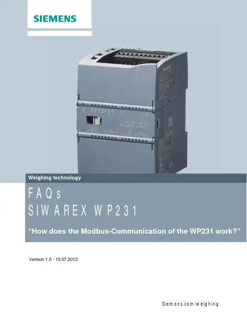
Version 1.0 - 15.07.2013Answer: The SIWAREX WP231 weighing modules offer a Modbus-TCP/IP and Modbus-RTU (RS485) communication. Please follow this FAQ in order to understand the mechanisms of the Modbus communication.This FAQ is based on the manual of the WP231, which is available online on:/WW/view/en/65621196Basic knowledge in weighing systems and Modbus communication is required to be able to use this FAQ.Before using this document, please check the manual of the WP231 for the right wiring of the 24V DC power supply, the loadcells, I/O’s and communication interfaces.If you run the WP231 without a SIMATIC S7-1200 CPU, please check the position of the “Stand-Alone-Mode” switch of the module:DIP-switch 1 has currently no function. Switch number 2 needs to be in the lower position for the Stand-Alone-Mode without PLC.The factory default is the upper position for PLC-integrated mode!The factory default settings of the Ethernet and Modbus-RTU interface of the WP231 are the following:Ethernet-Port:IP-address: 192.168.0.21 Subnet-Mask: 255.255.255.0 Standard-Gateway: 192.168.0.21RS485 port: Protocol: Modbus RTU Baud rate: 19200 Bits/s Parity: EvenData Bits: 8Stop Bits: 1Modbus Address: 20For the Modbus TCP/IP communication the Port 502 is used.All parameters of the WP231 weighing module are integrated in data records. It‘s possible to read or write a complete data record only! It‘s not possible to read or write one single parameter within a data record.Except the data records 30, 31, 32 and 34 (automatically refreshed) all data records need to be read/written into the Modbus-Registers by using special command codes. Please use the following syntax, in order to generate the right command code for reading a data record from the WP231 into the Modbus-Register or for writing data records from the Modbus-Registers into the WP231:- Read a data record from the WP231 into the Modbus-Registers:command code = 2000 + xx = number of the desired data record- Write a data record from the Modbus-Registers into the WP231:command code = 4000 + xx = number of the desired data recordFor all other commands like “Zero”, “Tare”, “Service Mode On”, “Service Mode off” and so on, please check the command list in the WP231 manual in order to find the right command codes!command 1 (highest priority) command 2 (medium priority) command 3 (lowest priority)data record 3 – Calibration Parameter data record 4 – Auto. Calibration Digits data record 5 – Tare/Zero/Memory data record 6 – Limitsdata record 7 – Process Interfacesdata record 8 – Date and Timedata record 9 – Module Infodata record 10 – Loadcell Parameters data record 12 – Ethernet Parameters data record 13 – RS485 Parameter data record 14 – S7 Interface Settings data record 15 – Preset Taredata record 16 – Weight Simulation data record 17 – Control Analogue Out data record 18 – Control Digital Outs data record 30 – Process Status*data record 31 – Process Status ext.* data record 32 – Data-Command-Errors* data record 34 – ASCII Weight Display*data record 3 – Calibration Parameter data record 4 – Auto. Calibration Digits data record 5 – Tare/Zero/Memorydata record 6 – Limitsdata record 7 – Process Interfacesdata record 8 – Date and Timedata record 9 – Module Infodata record 10 – Loadcell Parameters data record 12 – Ethernet Parameters data record 13 – RS485 Parameterdata record 14 – S7 Interface Settings data record 15 – Preset Taredata record 16 – Weight Simulationdata record 17 – Control Analogue Out data record 18 – Control Digital Outs data record 30 – Process Status*data record 31 – Process Status ext.* data record 32 – Data-Command-Errors* data record 34 – ASCII Weight Display** = data are refreshed automaticallyModbus-Registers(detailed information about the data records can befound in the WP231 manual)SIWAREX WP231 dataExample:You want to change the parameter “Adjustment Weight 1” which is included in the data record 3:1.) As data record 3 is accessible with active “Service Mode” only, you have to activate the “Service Mode”. You can find the right command code for this operation in the command list in the manual. “Service Mode On” Command Code “1”In our example we use command 2, with the medium priority.Command 2 has the following structure (see page 6):“Command_2_Code”“Command_2_Trigger”“Command_2_Finished”“Command_2_FinishedError”In order to switch on the Service Mode” you have to write “1” into the “command code 2” (=Modbus Register 920) and to set the “command trigger 2” “TRUE” (=Modbus Register 921).After that, the Service Mode should be active (DIAG led is flashing).2.) If you don’t know, whether the data of data record 3 in the Modbus Registers are up-to-date, you should read the record 3 from the WP231 into the Modbus-Registers first: As you want to read data record 3, you have to use the command code 2003(see page 3).Therefore you have to write “2003” into the “command code 2” (=Modbus Register 920) and to set the “command trigger 2” “TRUE” (Modbus Register 921=“1”).The data of data record 3 in the Modbus-Registers are up-to-date now!3.) Now you can edit the “Adjustment Weight 1” (=Modbus Register 1024).After that, you have to send the modified data record 3 from Modbus-Registers into the WP231 you have to use the command code 4003 now (see page 3)!Therefore you have to write “4003” into the “command code 2” (=Modbus Register 920) and to set the “command trigger 2” “TRUE” (Modbus Register 921=“1”).The modified data record 3 with your new Adjustment weight 1 is written into the WP231 now!4.) At the end we have to switch off the Service Mode again.“Service Mode Off” Command Code “2” (see command list in the manual)Therefore you have to write “2” into the “Command Code 2” (=Modbus Register 920) and to set the “Command Trigger 2” “TRUE” (Modbus Register 921=“1”).The Service Mode should be off now (DIAG led shouldn’t be flashing anymore)! Modbus-Command-Code StructuresCommand_1_Code USHORT 910 2Command_1_Trigger USHORT 911 2Command_1_Finished* USHORT 912 2Command_1_FinishedError* USHORT 913 2Command_2_Code USHORT 920 2Command_2_Trigger USHORT 921 2Command_2_Finished* USHORT 922 2Command_2_FinishedError* USHORT 923 2Command_3_Code USHORT 930 2Command_3_Trigger USHORT 931 2Command_3_Finished* USHORT 932 2Command_3_FinishedError* USHORT 933 2* = read only。
WGB-600系列微机保护测控装置选型及设计说明书(ver-1.00)许继集团股份有限公司XJ GROUP CORPORATION CO.,LTD.WGB-600系列微机保护测控装置1装置简介 11.1 功能配置 11.2 主要特点 12技术指标 12.1 额定数据 12.2 功耗 12.3 环境条件 22.4 抗干扰性能 22.5 绝缘性能 22.6 机械性能 22.7 各元件工作范围及误差 32.8 测量精度 33装置硬件 33.1 机箱结构 33.2 主要插件 44保护功能配置 44.1 WGB-611线路保护功能配置 44.2 WGB-631厂用变保护功能配置 54.3 WGB-641电容器保护功能配置 54.4 WGB-650电动机保护功能配置 64.5 WGB-661电压互感器监控功能配置 64.6 WGB-671电源备自投功能配置 64.7 遥测、遥信、遥控及遥脉功能 74.8 录波 74.9 G P S对时 75 装置对外接线 76 贮存及保修 247 供应成套性 248 订货须知241.装置简介1.1.适用范围:WGB-600系列微机保护测控装置实现中低压线路、变压器、电容器、电动机的保护和测控功能以及电压互感器的监控、备用电源自投等,主要用于35kV及以下各级电压等级。
1.2.主要特点a.加强型单元机箱按抗强振动、强干扰设计,特别适应于恶劣环境,可分散安装于开关柜上运行。
b.集成电路全部采用工业品或军品,使得装置有很高的稳定性和可靠性。
c.采用32位单片机作为保护CPU,配置大容量的RAM和Flash Memory;数据运算、逻辑处理和信息存储能力强,可靠性高,运行速度快。
d.采用16位A/D作为数据采集,数据采集每周24点,保护测量精度高。
e.采用图形液晶,全中文显示菜单式人机交互;可实时显示各种运行状态及数据,信息详细直观,操作、调试方便。
f.可独立整定8套保护定值,定值区切换安全方便。
WGB-631微机厂用变保护测控装置技术及使用说明书(ver-1.00)许继集团股份有限公司XJ GROUP CORPORATION CO.,LTD.WGB-631微机厂用变保护测控装置应用范围适用于3kV~10kV电压等级厂用变、所用变的保护及测控。
装置硬件后插拔方式,强弱电分离;加强型单元机箱按抗强振动、强干扰设计,可分散安装于开关柜上运行。
采用32位微机处理器,大容量的RAM和Flash Memory;数据处理、逻辑运算和信息存储能力强,运行速度快,可靠性高。
16位高精度AD,测量精度高。
可保存不少于80个最近发生的事件报告及运行报告。
采用图形液晶,中文显示,菜单式操作。
主要特点实时多任务操作系统,模块化编程;实时性好,可靠性高。
8套保护定值,定值区切换安全方便。
标准通信规约,方便与微机监控或保护管理机联网通讯。
完整的断路器操作回路,设置断路器遥控功能。
保护与测控一体化,单台装置完成间隔主要功能。
我公司保留对本说明书进行修改的权利;产品与说明书不符时,请参照实际产品说明。
2008.07 第一版印刷1装置简介 1 1.1 功能配置 1 1.2 主要特点 12技术指标 2 2.1 额定数据 2 2.2 功耗 2 2.3 环境条件 2 2.4 抗干扰性能 3 2.5 绝缘性能 3 2.6 机械性能 3 2.7 各元件工作范围及误差 3 2.8 测量精度 43装置硬件 4 3.1 机箱结构 4 3.2 主要插件 5 4保护原理 6 4.1 三段电流电压方向保护 6 4.2 过负荷保护 6 4.3 反时限过流保护 6 4.4 负序过流保护 7 4.5 高压侧零序保护 7 4.6 低压侧零序定时限保护 7 4.7 低压侧零序反时限保护 8 4.8 低电压保护 8 4.9 零序电压保护 8 4.10 PT断线告警 9 4.11 非电量保护 9 4.12 备用非电量保护 9 4.13 控制回路异常 10 4.14 手车位置异常告警 10 4.15 跳位异常告警 10 4.16 弹簧未储能告警 11 4.17 装置故障告警 114.18 遥测、遥信、遥控及遥脉功能 114.19 录波 114.20 G P S对时 115 定值范围及动作告警信息 11 5.1 压板整定信息 11 5.2 定值整定及说明 12 5.3 动作信息及说明 136 装置对外接线 15 6.1 装置对外接线 15 6.2 装置辅助电源 15 6.3 交流电流及电压输入 15 6.4 开入及开入电源 15 6.5 信号及控制回路 15 6.6 通信端子 167 人机界面说明 167.1 键盘说明 16 7.2 运行显示 16 7.3 菜单结构 16 7.4 菜单操作 17 7.5 浏览 18 7.6 记录 18 7.7 整定 19 7.8 调试 20 7.9 设置 22 7.10 版本 258 调试及异常处理 26 8.1 调试说明 26 8.2 程序检查 26 8.3 开关量输入检查 26 8.4 继电器回路检查 26 8.5 模拟量输入检查 26 8.6 整组试验 268.7 异常处理 269 IEC60870-5-103规约点表 27 9.1 保护动作故障信号 27 9.2 告警信号 27 9.3 状态信号 28 9.4 控制信号 28 9.5 遥测信号 29 9.6 电镀信号 29 9.7 总召唤信息 29 9.8 录波 2910 投运说明及注意事项 3011 贮存及保修 3012 供应成套性 3013 订货须知3114 附图1:装置面板布置图32附图2:装置背面端子图33附图3:装置接线示意图34附图4:控制回路原理图351.装置简介WGB-631微机厂用变保护装置主要适用于3~10kV电压等级小电流接地系统或小电阻接地系统中的厂用变、所用变或接地变的保护。


FAQSIWAREX WP231WP231模块的Modbus通信是如何工作的?解答:称重模块SIWAREX WP231支持Modbus-TCP/IP和Modbus-RTU (RS485)通信。
通过该文档可以了解Modbus的通信机制。
该文档是在WP231手册基础上编写的,手册下载链接如下:/WW/view/en/65621196读者必须具备称重系统和Modbus通信的基础知识。
在使用该文档之前,首先通过手册检查WP231的24V电源、称重传感器和输入输出端子接线是否正确。
如果WP231独立运行,没有S7 1200控制器,请确认“独立运行模式”开关位置是否正确:DIP开关1目前还没有功能。
对于独立运行模式,DIP开关2需要拨到下方。
模块出厂时开关2是拨到上方的,用于PLC集成模式。
WP231模块的以太网和Modbus-RTU接口,默认设置如下:Modbus TCP/IP通信使用的端口为502。
WP231模块的所有参数都存储在数据记录中,数据记录只能整体读写,不能仅对数据记录中的某一个参数进行读写。
除了数据记录30,31,32和34自动更新外,其他数据记录必须通过特殊的命令代码读取到Modbus寄存器中。
请使用下列公式得到正确命令代码:将WP231的参数读取到Modbus寄存器中:命令代码= 2000 + xx 为要访问的数据记录的编号将Modbus寄存器中的内容写入到WP231模块:命令代码= 4000 + xx 为要访问的数据记录的编号对于其它命令,如清零、去皮、打开服务模式、关闭服务模式等,请参考WP231模块使用手册中的命令列表。
Modbus寄存器 WP231参数(在WP231手册中可以看到数据记录的详细信息。
)举例:比如要修改数据记录3中的标定砝码重量1 “Adjustment Weight 1” :(1)数据记录3必须在服务模式下才能访问,所以首先要打开服务模式。
通过手册我们可以查到打开服务模式对应的命令代码为1。
公司简介公司自行设计、制造的系列超声热压金丝球焊机体现了我们的工程师卓越的才能及一丝不苟、精益求精的追求,代表了本公司在微电子焊接技术上专业的水平以及丰富的经验,也代表了国内半导体器件内引线焊接设备的发展里程。
公司在技术上积极地、大力地投入,使产品性能得到不断地改进,质量得到可靠保障。
精湛的技术,真诚的服务,是我们的追求和骄傲!精湛的技术,真诚的服务,是我们的追求和骄傲!前言首先,我们感谢您选择了本公司的2310 超声波金丝球焊机!感谢您对我们的信任!感谢您对我们的支持!本机可应用于发光二极管、中小型功率三极管、集成电路和一些特殊半导体器件等内引线焊接。
它是本公司众多工程技术人员辛勤工作、努力创造的结果,经过长期的实践及改进,得到了各个行业广大客户的推崇。
大量相关企业长期使用证明,本机型具备优良的品质、可靠的性能,代表了本公司在超声波微焊接设备的发展里程。
我们有信心——2310型超声波金丝球焊机给您带来不菲的回报型超声波金丝球焊机给您带来不菲的回报菲的回报!我们有信心为了你正确使用该机器,请您在操作之前,仔细阅读本说明书。
为了你正确使用该机器,请您在操作之前,仔细阅读本说明书。
目录1.概述………………………………………………………………………5概述1.1 用途 (5)1.2 特点 (5)2.主要技术参数32.1 电源 (6)2.2 超声波发生器 (6)2.3 换能器 (7)2.4 可焊金丝线径与线轴轴径 (7)2.5 焊接压力 (7)2.6 温度 (8)2.7 成球 (8)2.8 机械参数调节范围及运行周期 (8)2.9 光学系统 (8)2.10 环境要求 (8)2.11 机器外形尺寸与重量 (9)3. 主要结构及部分功能介绍主要结构及部分功能介绍 (9)3.1 主要结构 (9)3.2 主要部件功能 (9)4. 工作原理工作原理 (14)4.1 超声波的焊接原理 (14)4.2 机器工作循环过程 (14)5. 机器安装机器安装 (15)5.1 开箱及显微镜安装 (15)5.2 壁刀安装 (15)5.3 金丝安装 (16)6. 操作及调整操作及调整 (16)6.1 操作 (16)6.2 焊头初始高度及打火杆的调节 (17)6.3 高度、跨度的调节 (17)6.4 线夹调节 (19)6.5 尾丝及金球大小的调节 (19)6.6 弧度调节 (20)6.7 焊头压力调节及测试 (21)6.8 超声功率及时间调节 (21)6.9 温度调节 (21)6.10 照明灯调节 (21)6.11 显微镜的调整 (21)7. 机器日常保养 (22)7.1 劈刀的清洗 (22)7.2 线夹宝石片的清洗 (22)7.3 触点清洁 (22)7.4 放线系统及打火杆的清洁 (23)7.5 重要机械部分的保养 (23)7.6 显微镜的保养 (23)8. 焊接相关常识 (24)8.1 劈刀 (24)8.2 金丝 (24)8.3 焊接四要素 (24)8.4 劈刀堵塞的处理 (24)9. 故障解决方案 (25)9.1 常见故障排除 (25)9.2 技术支持 (27)1.概述概述1.1 用途3030 金丝球焊机可应用于发光二极管、中小型三极管、集成电路和一些特殊半导体器件内引线的焊接。
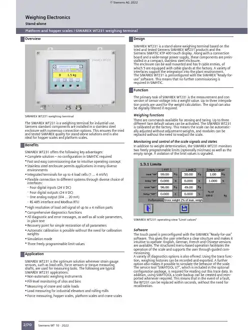
Stand-aloneOverviewPlatform and hopper scales / SIWAREX WT231 weighing terminalPlatform and hopper scales / SIWAREX WT231 weighing terminal2/70SIWAREX WT231 weighing terminalThe SIWAREX WT231 is a weighing terminal for industrial use.Siemens standard components are installed in a stainless steelenclosure with numerous connection options. This ensures the tried and tested SIWAREX quality for stand-alone solutions and is alsoideal for hopper scales and platform scales.SIWAREX WT231 offers the following key advantages:•Complete solution – no configuration in SIMATIC required•Fast and easy commissioning due to intuitive operating concept •Stainless steel enclosure permits applications in many diverse environments•Integrated terminals for up to 4 load cells (1 … 4 mV/V)•Flexible connection to different systems through diverse choice of interfaces:-Four digital inputs (24 V DC)-Four digital outputs (24 V DC)-One analog output (0/4 … 20 mA)-RS 485 interface and Modbus RTU•High resolution of load cell signal of up to ± 4 million parts •Comprehensive diagnostics functions•All diagnostic and error messages, as well as all scale parameters,in plain text•Recovery point for simple restoration of all parameters•Automatic calibration is possible without the need for calibration weights•Simulation mode•Three freely programmable limit valuesSIWAREX WT231 is the optimum solution wherever strain gauge sensors, such as load cells, force sensors or torque measuring shafts, are used for measuring tasks. The following are typical SIWAREX WT231 applications:•Non-automatic weighing instruments •Fill-level monitoring of silos and bins •Measuring of crane and cable loads•Load measuring for industrial elevators and rolling mills•Force measuring, hopper scales, platform scales and crane scalesSIWAREX WT231 is a stand-alone weighing terminal based on the tried and tested Siemens SIWAREX WP231 products and theSiemens SIMATIC KTP 400 touch display. Along with a connection board and a wide-range power supply, these components are preinstalled in a compact, stainless steel enclosure.The enclosure can be wall mounted and has 9 cable entries, of which 5 are equipped with cable glands at the factory. A variety of interfaces support the integration into the plant environment.The SIWAREX WT231 is preconfigured with the SIWAREX "Ready-for-use" software. This means that no further commissioning isrequired in SIMATIC.The primary task of SIWAREX WT231 is the measurement and conversion of sensor voltage into a weight value. Up to three interpolation points are used for the weight calculation. The signal can also be digitally filtered if required.Weighing functionsThere are commands available for zeroing and taring. Up to three different tare default values can be activated. The SIWAREX WT231is calibrated at the factory. This means the scale can be automatically adjusted without adjustment weights, and modules can be replaced without the need to readjust the scale.Monitoring and control of the scale signals and statesIn addition to weight determination, the SIWAREX WT231 monitorstwo freely programmable limits (optionally min/max) as well as the empty range. A violation of the limit values is signaled.SIWAREX WT231 operating view "Limit values"SoftwareThe touch panel is preconfigured with the SIWAREX "Ready-for-use"software. This gives the user interface a clear structure and makes it intuitive to operate: English, German, French and Chinese versions are available. The structured menu-based operation facilitates the operation of the scale and supports the user through guided commissioning.A variety of diagnostics options is also offered: Using the trace function, weighing histories can be recorded and exported. A further option also makes it possible to simulate the behavior of the scale.The service tool "SIWATOOL V7", which is included in the optional configuration package, is required for reading out this trace data. In addition, using SIWATOOL a scale backup can be created and reimported whenever required. This means that in the event of a fault,the WT231 can be replaced within seconds, without the need for recalibration.Siemens WT 10 · 2022Stand-aloneWeighing Electronics© Siemens AG 2022Stand-alonePlatform and hopper scales / SIWAREX WT231 weighing terminal2/71Integration in the plant environmentUsing the onboard RS 485 interface and the Modbus RTU protocol,the SIWAREX WT231 can be connected to a wide range of different automation systems or to a PC.Four digital inputs, four digital outputs und one analog output are also available. Direct, straightforward further processing of alarms or status messages is thus made possible.Siemens WT 10 · 2022Weighing ElectronicsStand-alonePlatform and hopper scales / SIWAREX WT231 weighing terminal2/72Siemens WT 10 · 2022Weighing Electronics。
SIWAREX WT231: The new weighing terminal is a stand-alone package that is comprised of tried-and-tested Siemens components: Flexible weighing electronics and user-friendly Siemens Touch Panel/weighing2The new SIWAREX WT231 weighing terminal combines the proven quality of two Siemens components into one product: a powerful SIWAREX WP231 weighing module, and a Siemens Touch Panel with an application-specific user interface.All settings and parameters for applications in the areasof level measurement and platform scales can be madevia the Touch Panel.The intuitive operation enables the user to perform fastparameter assignment and commissioning.As a stand-alone solution, the SIWAREX WT231 can beused independently of the automation solution,making interaction fast and uncomplicated.The RS485 Modbus RTU interface enables a directintegration of the terminal in all conventional controllerenvironments.The control components used in the terminalstand-out on their own as individual products with exceptional quality:• S IWAREX WP231: The flexible weighing module is the ideal solution for industrial areas with high precision requirements, e.g. food and beverages, pharmaceuti-cals, chemicals, and many more. The comprehensive diagnostics options, such as checking weight progres-sion or monitoring and reporting limit values, increase process reliability• S iemens Touch Panel: The 4-inch panel with TFT wide-screen color display offers a high screen resolution and enables use in very tight spaces without compromising functionality.The modular weighing terminal meets the very high qual-ity demands of various sectors, such as the food and bev-erages, pharmaceutical, and chemicals industries.With the SIWAREX WT231, practical use of reliable quality is possible.The whole package – proven quality for flexible weighing technology• V ersatile weighing modul e – Comprehensive diagnostics functions, monitoring of limits, high resolution of up to +/- four million parts , high accuracy of 0.05%, measuring rate of 10 ms• H igh-quality HMI Panel – 4-inch TFT widescreen display with 256 colors, screen resolution 480 × 272 px, touch-screen, 4 function keys• I ntuitive user interface ‒ suitable for applications in the area of level measurement and platform scales• F lexible connectio n ‒ Connection to all automation systems that support Modbus RTU protocol• H igh-quality material ‒ With IP65 degree of protection, the high-quality stainless steel housing fulfills the typicalindustrial requirementsThe information provided in this brochure contains merely descriptions or performance characteristics which in case of actual use do not always apply as described or which may change as a result of further development of the products.An obligation to provide the desired performance features shall only exist if expressly agreed in the terms of contract.All product designations may be trademarks or prod-uct names of Siemens AG or supplier companies whose use by third parties for their own purposes could violate the rights of the owners.Siemens AGProcess Industries and Drives Östliche Rheinbrückenstr. 5076187 Karlsruhe GermanySubject to change without prior notice Article No.: PDPA-B10003-00-7600Dispo 06319Printed in Germany© 04/2015, Siemens AGFollow us on:/siemenssensors /thinksiemens /siemenssensors.More Information:/weighing。
健伍TM-231/TM-241操作说明注意事项安全顾虑§拆装本机时,应参考本手册。
随意触摸本机内部,有触电、甚至电击之虑。
电源电压§本机电源采铅酸电池组的电压公称值,是13.8V。
要注意某些车种可能采用更高电压,例如大卡车等。
请勿误装24V供电。
§金属物,如发夹、回纹针等,万一碰撞机背的电源坐,可能有电源短路之虑。
尤其应防小孩完耍,把小金属物插入本机内。
安装§请勿把本机安装在太阳直射处、或靠近发热的电器电机旁。
§请勿把本机储存在多尘、高湿环境中,更不可在这样的环境下使用。
应选择通风处存放。
§如有烧焦异味或冒烟,应立即关机,并拔除电源。
为了保持通风良好、本机维持正常运作,不要把书籍、纸张堆积在本机上头。
§安装时,本机应离墙最少10公分以上,以维持通风,正常散热。
电源§使用电源时,插电应注意,避免手湿操作,以防触电。
§电源供应器直流输出电缆慎防拉扯,会有破皮及短路之虑。
保持干净§为了保持乾净,请勿以高挥发性溶剂清洗本机,如酒精、油漆稀释液、汽油、苯、去渍油等都在禁止之列。
以干净布块轻轻擦拭即可。
装机车机安装§安装电源线时,为了安全起见,应暂把电池负电端拔除,以防意外短路。
接好电源线后,应细心检查,无误后再把负电端接回。
§如果保险丝烧毁,应小心检查接线是否破皮短路,再更换保险丝。
接线完了之后,保险丝盒应以耐高温胶带缠绕,以防高温及湿气。
§本机所附电源线太长时,绝对不能剪去保险盒部份。
电源请直接由电池取出,使用点烟器插孔容易接触不良。
接电源时,要注意极性。
§本机在设计时,已考虑车上引擎发出的杂讯,若杂讯过大,还是要另行加装杂讯消除器。
基地台安装§使用电源时,电压在13.8V下,电流必须11安培才够用。
§为了安全起见,直流电源线装妥时,才把电源的AC插头插上。
0XJ 461 167第 2 页共 42 页旧底图总号底图总号签字日期4.3.7. 低电压保护 (17)4.3.8. 二段定时限负序过流保护 (17)4.3.9. 低压侧零序反时限过流保护 (18)4.3.10. FC回路保护 (18)4.3.11. 非电量保护 (19)4.3.12. TV断线检测 (19)4.4. 控制回路异常告警 (19)4.5. 弹簧未储能告警 (19)4.6. 装置故障告警 (19)4.7. 测控功能 (20)4.8. 辅助功能 (20)4.8.1. 录波 (20)4.8.2. GPS对时 (21)4.8.3. 网络通信 (21)5. 装置使用说明 (21)5.1. 定值整定 (21)5.1.1. 投退控制字 (21)5.1.2. 功能控制字 (22)5.1.3. 保护定值 (23)5.2. 动作信息及说明 (24)5.3. 人机界面说明 (24)5.3.1. 面板说明 (24)5.3.2. 按键与显示屏 (25)5.3.3. 指示灯 (25)5.3.4. 显示说明 (25)5.3.5. 菜单结构 (26)5.3.6. 浏览菜单 (26)5.3.7. 整定菜单 (28)5.3.8. 设置菜单 (29)5.3.9. 调试菜单 (30)5.3.10. 版本 (32)5.3.11. 自动信息显示 (32)6. 调试及异常处理 (32)6.1. 调试说明 (33)6.2. 程序检查 (33)6.3. 开关量输入检查 (33)6.4. 继电器开出回路检查 (33)6.5. 模拟量输入检查 (33)6.6. 相位检查 (33)6.7. 整组试验 (33)6.8. 异常处理 (33)7. 投运说明及注意事项 (34)8. 定值整定说明 (34)8.1. I段、II段过流保护 (34)0XJ 461 167第 3 页共 42 页旧底图总号底图总号签字日期8.1.1. 高压侧电流速断保护(Ⅰ段电流保护)(j dz I.,T1) (34)8.1.2. 高压侧过电流保护(Ⅱ段电流保护)(j dz I.,T2) (35)8.2. 高压侧零序过电流保护 (36)8.3. 低压侧零序过流保护(j dz I.,T) (36)8.4. 瓦斯保护 (36)8.5. 高压侧不平衡电流(负序电流)保护(j dz I.,T) (36)9. 通信说明 (37)9.1. 保护动作信号 (37)9.2. 告警信号 (37)9.3. 状态信号 (38)9.4. 控制 (38)9.5. 遥测 (39)9.6. 电度 (39)9.7. 总召唤信息 (39)10. 贮存及保修 (39)10.1. 贮存条件 (39)10.2. 保修时间 (39)11. 供应成套性 (39)11.1. 随同产品一起供应的文件 (39)11.2. 随同产品一起供应的附件 (40)12. 订货须知 (40)13. 附图 (41)13.1. 装置接线示意图 (41)13.2. 装置操作回路原理图 (42)0XJ 461 167第 4 页共 42 页旧底图总号底图总号签字日期1. 应用范围WCB-831A微机厂用变保护测控装置,是许继秉承数十年来在电力系统二次设备制造领域的成功经验,为用户提供的具有高品质、高性价比的保护测控一体化装置。
WGB-231A微机厂用变保护测控装置技术及使用说明书(Version 1.00)许继电气股份有限公司XJ ELECTRIC CO.,LTD.WGB-231A微机厂用变保护测控装置WGB-231A微机厂用变保护测控装置是许继最新推出的HELLO系列产品之一,它是许继秉承数十年来在电力系统二次设备制造领域的成功经验,为用户提供的具有高品质、高性价比的保护测控一体化装置。
WGB-231A微机厂用变保护测控装置主要适用于3~10kV电压等级小接地电流系统或小电阻接地系统中的厂用变、所用变或接地变的保护及测控。
H、E、L、L、O品质是许继HELLO系列产品的共同特点,具体如下:⏹H:即High,高品质包括:◆高科技:采用现场组态技术(FCT)、可视化的软件开发技术(VLD)。
◆高质量:以专业的、成熟的软硬件平台为依托,丰富的运行经验和充分验证的原理算法为基础,自动测试为前提,先进的研发管理理念和研发开发管理工具为手段,保证研发、生产、制造过程中各个环节的质量,为用户提供高品质的产品。
⏹E:即Easy,工作轻松包括:◆易使用:人机界面友好、仿WINDOWS操作菜单,具有调试向导系统和一键完成定检功能,使现场调试、维护、定检工作变得轻松。
⏹L:即Low,低消耗包括:◆低投入成本:不同的装置共享插件,降低了购买装置和备件储备成本。
◆低故障率:先进的检测技术和完善的生产质量保障体系,使得产品的故障大大降低,大幅度减少了被保护对象的停运时间。
⏹L:即reaLize,实现技术包括:◆平台化:软件、硬件的设计都采用平台化的思想,使不同电压等级的保护装置可以共享硬件平台,不同的硬件平台可以共享软件,降低了日后硬件、软件的升级和维护工作。
◆专业化:不同领域的研发工作都由专业人员完成,通过规范的接口集成不同层次、不同领域的研发成果,让用户充分享受到高科技的产品。
◆模块化:对所有的功能模块分别封装成柔性继电器,不同装置通过配置不同的柔性继电器完成该装置的功能,能够顺速响应不同用户的个性化需求。
⏹O:即technOlogy,专利技术包括:◆VLD开发技术:VLD开发工具类似与“PLC”的开发环境,在该环境下所有的保护逻辑都是由不同可视化的柔性继电器组成,实现了业界用继电保护语言开发程序的梦想。
◆双连接器技术:采用后插拨双连接器的技术,强弱电彻底分离的原则,提高了装置硬件电磁兼容能力。
感谢您使用许继电气股份有限公司的产品。
为了安全、正确、高效地使用本装置,请您务必注意以下重要提示:本说明书仅适用于WGB-231A微机厂用变保护测控装置。
请仔细阅读本说明书,并按照说明书的规定调整、测试和操作。
如有随机资料,请以随机资料为准。
为防止装置损坏,严紧带电插拔装置各插件、触摸印制电路板上的芯片和器件。
请使用合格的测试仪器和设备对装置进行试验和检测。
装置如出现异常或需要维修,请及时与本公司服务热线联系。
我公司保留对本说明书进行修改的权利;产品与说明书不符时,以实际产品为准,恕不另行通知。
目录1技术指标 (1)1.1额定数据 (1)1.2装置功耗 (1)1.3环境条件 (1)1.4抗干扰性能 (2)1.5绝缘性能 (2)1.6机械性能 (3)1.7保护定值整定范围及误差 (3)1.8测量精度 (4)1.9触点容量 (4)2装置硬件 (4)2.1机箱结构 (4)2.2硬件平台说明 (5)2.3软件平台说明 (5)2.4插件配置 (5)2.4.1电源插件 (6)2.4.2交流插件 (6)2.4.3CPU插件 (6)2.4.4信号插件 (6)2.4.5人机对话插件 (6)2.5装置背面端子图 (6)2.6装置辅助电源 (8)2.7交流电流输入 (8)2.8交流电压输入 (8)2.9开入及开入电源 (8)2.10跳合闸回路 (8)2.11通信端子 (9)3装置功能 (9)3.1装置功能实现方式 (9)3.2典型功能配置 (9)3.3保护功能 (10)3.3.1三段二时限复压闭锁过流保护 (10)3.3.2高压侧反时限过流保护 (10)3.3.3过负荷保护 (11)3.3.4高压侧三段零序过流保护 (11)3.3.5低压侧三段零序过流保护 (12)3.3.6零序过压保护 (12)3.3.7低电压保护 (13)3.3.8二段定时限负序过流保护 (13)3.3.9低压侧零序反时限过流保护 (13)3.3.10FC回路保护 (14)3.3.11非电量保护 (14)3.3.12TV断线检测 (15)3.4控制回路异常告警 (15)3.5弹簧未储能告警 (15)3.6装置故障告警 (15)3.7测控功能 (15)3.8辅助功能 (16)3.8.1录波 (16)3.8.2GPS对时 (17)3.8.3网络通信 (17)4装置使用说明 (17)4.1定值整定 (17)4.1.1投退控制字 (17)4.1.2功能控制字 (18)4.1.3保护定值 (19)4.2动作信息及说明 (20)4.3人机界面说明 (20)4.3.1面板说明 (20)4.3.2按键与显示屏 (21)4.3.3指示灯 (21)4.3.4显示说明 (21)4.3.5菜单结构 (22)4.3.6浏览菜单 (22)4.3.7整定菜单 (24)4.3.8设置菜单 (25)4.3.9调试菜单 (27)4.3.10版本 (28)4.3.11自动信息显示 (29)5调试及异常处理 (29)5.1调试说明 (29)5.2程序检查 (29)5.3开关量输入检查 (29)5.4继电器开出回路检查 (29)5.5模拟量输入检查 (30)5.6相位检查 (30)5.7整组试验 (30)5.8异常处理 (30)6投运说明及注意事项 (30)7定值整定说明 (31)7.1I段、II段过流保护 (31)7.1.1 高压侧电流速断保护(Ⅰ段电流保护)(j dz I .,T1)..........................................................31 7.1.2 高压侧过电流保护(Ⅱ段电流保护)(j dz I .,T2) .. (31)7.2 高压侧零序过电流保护.....................................................................................................................32 7.3 低压侧零序过流保护(j dz I .,T ) ...............................................................................................32 7.4 瓦斯保护 ...............................................................................................................................................33 7.5 高压侧不平衡电流(负序电流)保护(j dz I .,T) . (33)8通信说明 ........................................................................................................................................................34 8.1 保护动作信号 ......................................................................................................................................34 8.2 告警信号 ...............................................................................................................................................34 8.3 状态信号 ...............................................................................................................................................35 8.4 控制 ........................................................................................................................................................35 8.5 遥测 ........................................................................................................................................................35 8.6 电度 ........................................................................................................................................................35 8.7总召唤信息 (36)9 贮存及保修 ....................................................................................................................................................36 9.1 贮存条件 ...............................................................................................................................................36 9.2保修时间 ...............................................................................................................................................36 10 供应成套性 ...............................................................................................................................................36 10.1 随同产品一起供应的文件 ................................................................................................................36 10.2 随同产品一起供应的附件 ................................................................................................................36 11 订货须知....................................................................................................................................................36 12 附图.............................................................................................................................................................37 12.1 装置接线示意图 ..................................................................................................................................37 12.2 装置操作回路原理图 . (38)1 技术指标1.1 额定数据a.额定电源电压: AC/DC220Vb.额定交流数据:交流电压: 100/3V,100V零序电压: 100V交流电流: 5A或1A(订货注明)高压侧零序电流: 1A低压侧零序电流:5A额定频率: 50Hzc.热稳定性:交流电压回路:长期运行 1.2Un交流电流回路:长期运行 2In1s 40In高压侧零序电流回路:长期运行 2A1s 40A低压侧零序电流回路:长期运行 10A1s 200Ad.动稳定性:半周波100In1.2 装置功耗a.交流电压回路:每相不大于1VA;b.交流电流回路: In=5A时每相不大于1VA;In=1A时每相不大于0.5VA;c.高压侧零序电流回路: 不大于0.5VA;d.低压侧零序电流回路:In=5A时每相不大于1V A;In=1A时每相不大于0.5V A;e.电源回路:正常工作时不大于12W;保护动作时不大于15W。