EW-NET542快速安装指南
- 格式:doc
- 大小:2.23 MB
- 文档页数:15

NETGEAR 无线宽带路由器快速安装手册(本文适合用于NETGEAR WGR614v5/v6/WGT624v3/WPN824v1),以WGR614v6 进行说明:第1步将WGR614v6接入网络∙目前一般的家庭或小型办公网络最常使用的是ADSL接入,直接用电脑拨号上网时的网络连接如下:∙使用WGR614v6实现共享上网,若使用有线,正确的连接方式如下:∙电脑应先连接到WGR614v6的四个局域网端口之一(见上图C曲线)∙再用另一条网线将WGR614v6的互联网端口(路由器上单独的那个端口)与ADSL MODEM连接(见上图)。
第2步电脑网络属性配置∙在配置路由器前,首先要对用来管理路由器的电脑进行网络属性的配置,下面以Windows XPHome Edition Service Pack 2为例来说明电脑的配置过程:2.1. 启动电脑,右键单击桌面或“开始”中的“网上邻居”选“属性”,右键单击“本地连接”选“属性”,选中“Internet协议(TCP/IP)”,点击“属性”:2.2. 将电脑设为“自动获得IP地址”,“自动获得DNS服务器地址”点击“确定”:第3步登录路由器3.1. 确保电脑已按照第一步所述通过有线连接到路由器的四个LAN口之一,启动路由器。
3.2. 打开电脑的Internet Explorer或者Netscape Navigator等其他浏览器,在浏览器的地址栏键入http://192.168.1.1/basicsetting.htm后回车:『注』初次设置路由器须按以上步骤,以后管理路由器或者更改配置,只需要在IE浏览器中输入192.168.1.1,此时路由器会要求提供用户名和密码。
登录路由器用户名:admin,密码:password,都是小写:默认进入的页面是”基本设置”页面,如图:『注意』无论您的宽带采用何种接入方式,都须先通过有线方式连接到路由器,在基本设置页面中进行相应的设置,完成后无线收发功能才会开启,才可使用无线连接。

打印服务器安装安装过程其实很简单,根据说明书上的介绍几分钟就可以完成。
因为打印服务器和路由器一样出厂的时候有预设了WEB管理的IP地址,所以我们可以通过网页或它随机的管理软件对进行管理和设置。
但首先要求把打印服务器的IP地址设置到局域网同一个子网中来。
设备网卡IP地址先把打印机接到打印服务器上,接通打印服务器和打印机的电源就可以开始安装了。
由于打印服务器的预设IP是192.168.0.50,所以我们也要先设置自已的电脑到它同一个网段中,进入管理界面后就可以修改打印服务器的IP地址了。
传统的打印服务器,要装系统、装驱动、再配置,十分麻烦,而TP-LINK的打印服务器让你省去了不少步骤,连接好之后,在每台使用电脑上添加一下就可以了。
产品自带配置工具放入光盘可以配置简单的向导就不多说了我们来手动配置和配置路由器一样 PS110U的配置界面配置选项很少十分容易一般主要配置这一步就可以了根据自己的局域网进行配置还可以升级固件得到更多的支持重新启动功能经过简单的配置,你的打印机服务器就已经在局域网之中了,简单吧!剩下的工作,就是让每台电脑找到并使用它。
系统兼容性好客户端添加打印机步骤这系列产品兼容性不错,支持的终端操作系统也多,我们下面以Vista为例,进行一下添加打印机的操作,过程十分简单,操作熟练的话,连一分钟都用不了。
打开控制面板的打印机选项,按右键选择添加打印机,前提是你的这台计算机和打印服务器在一个网内。
选择网络打印机选第三项最快填入打印服务器的IP地址(刚才配置过的),之后选择自定义设备类型,协议改为LPR,队列名称填入的LP1,把启用了LPR字节计数钩上。
之后安装打印机的相关驱动这个找到对应驱动就自己装了输入打印机的名称添加成功了,现在可以正常使用打印机了,我们打个测试页看一看。
连接正常,没有问题,这样一台终端就搞定了,如果是XP系统,那可能在添加的过程中有一些区别,请按照说明书添加即可。
总之,过程很简单,没有门槛,比自己配置计算机型服务器要方便不少。

Guide d’installation du point d’accès Wi-Fi CPL 500 XWN5001Support techniqueNous vous remercions d'avoir choisi les produits NETGEAR.Après l'installation de votre périphérique, notez le numéro de série inscrit surl'étiquette de votre produit. Il vous sera nécessaire pour enregistrer votre produit à l'adresse https://.Vous devez enregistrer votre produit avant de pouvoir utiliser l'assistancetéléphonique de NETGEAR. NETGEAR vous recommande d'enregistrer votre produit sur le site Web de NETGEAR.Téléphone (Etats-Unis uniquement) : 1-888-NETGEARTéléphone (autres pays) :Rendez-vous à l'adresse /general/contact/default.aspx. NETGEAR vous recommande d'utiliser uniquement les ressources d'assistance officielles NETGEAR.Marques commercialesNETGEAR, le logo NETGEAR et Connect with Innovation sont des marques commerciales et/ou des marques déposées de NETGEAR, Inc. et/ou des filiales de NETGEAR aux Etats-Unis et/ou dans d'autres pays. Les informations sont sujettes à changement sans préavis. © NETGEAR, Inc. Tous droits réservés.Table des matièresContenu de la boîte. . . . . . . . . . . . . . . . . . . . . . . . . . . . . . . . . . 2 Caractéristiques matérielles . . . . . . . . . . . . . . . . . . . . . . . . . . . 3 Description des voyants . . . . . . . . . . . . . . . . . . . . . . . . . . . . . . 4 Descriptions des boutons . . . . . . . . . . . . . . . . . . . . . . . . . . . . . 5 Installer le point d'accès et surfer sur le Web via WiFi . . . . . . . 6 Installez NETGEAR genie. . . . . . . . . . . . . . . . . . . . . . . . . . . . 19 Périphériques NETGEAR CPL compatibles . . . . . . . . . . . . . . 20Contenu de la boîteXWN5001Câble EthernetCaractéristiques matériellesPoint d’accès WiFi CPL 500(XWN5001)Voyantd'alimentation Voyant CPL Voyant sans fil.BoutonSécuritéBouton deréinitialisa-tionPortEthernet Voyant Ethernet Bouton d'alimentation.Description des voyantsLes voyants indiquent l'état de vos adaptateurs CPL.•Lorsque vous branchez l'adaptateur, le voyant d'alimentation s'allume en vert.•Le voyant Ethernet s'allume lorsque vous connectez un périphérique Ethernet sous tension à au moins un port Ethernet. Si le voyant est éteint, il n'y a pas de connexion Ethernet.•L'adaptateur est inactif lorsqu'aucun lien Ethernet n'a été établi depuis plus de 10 minutes. L'adaptateur entre alors en modeéconomie d'énergie et le voyant d'alimentation devient orange.•Le voyant CPL s'allume lorsque le périphérique CPL détecte au moins un autre périphérique CPL compatible.La fonction Pick A Plug vous permet de choisir la prise électrique ayant le débit de connexion le plus rapide.- Vert : Débit de connexion > 80 Mbit/s (Rapide)- Orange : Débit de connexion > 50 et < 80 Mbit/s (Moyen) - Rouge: Débit de connexion < 50 Mbit/s (Lent)Descriptions des boutonsLes boutons de vos adaptateurs CPL vous permettent d'effectuer les actions suivantes :•Réinitialisation : Utilisez le Bouton de réinitialisation pour rétablir votre adaptateur CPL à ses paramètres d'usine par défaut. Appuyez sur le Bouton de réinitialisation pendant 2 secondes, puisrelâchez-le.•Bouton d'alimentation : Utilisez le bouton d'alimentation pour mettre l'appareil sous et hors tension.•Bouton de sécurité : Le bouton de sécuritéa trois fonctions : -Sécuriser le réseau CPL.-Créez un point d'accès WiFi sur le XWN5001 possédant les mêmes paramètres sans fil que votre routeur ou votrepasserelle.-Connectez automatiquement votre client sans fil au point d'accès WiFi du XWN5001.Installer le point d'accès et surfer sur le Web via WiFi1. Sécurisation de votre réseau CPLCes instructions présupposent que vous avez déjà un réseauCPL qui comprend au moins 2 périphériques CPL et que vous souhaitez ajouter le XWN5001 à votre réseau.a.Assurez-vous que le voyant d'alimentation de chaquepériphérique CPL est vert continu.b.Sur un périphérique CPL connecté à votre réseau CPLexistant, appuyez sur le bouton Sécurité pendant 2secondes, puis relâchez le bouton. Le voyant d'alimentationclignote en vert pendant la sécurisation du périphérique.c.Dans les deux minutes qui suivent, appuyez sur le boutonSécurité du XWN5001 pendant deux secondes, puisrelâchez-le.d. Après quelques secondes, la sécurité est installée. Lesvoyants d'alimentation doivent être verts continu.Les périphériques CPL peuvent communiquer sur le réseau CPL de manière sécurisée.2.Branchez l'un de vos périphériques CPL à une prise muraleproche de votre routeur ou de votre passerelle.Si vous voulez partager l'accès Internet dans votre maison, assurez-vous de connecter le périphérique CPL à votrepasserelle Internet avec un câble Ethernet.Réseau CPL existant3.Branchez le XWN5001 à une prise murale où vous avez besoind'une couverture WiFi .Réseau CPL existantAjouter un WiFi point d'accèsRemarque : Vous pouvez connecter un périphérique Ethernet (comme une console de jeu, un décodeur, ou un lecteur Blu-ray) à Internet et au réseau domestique avec le port Ethernet supplémentaire sur leXWN5001.4.Configurez un accès WiFi sur votre point d'accès XWN5001.Vous pouvez configurer l'accès WiFi sur votre point d'accèsXWN5001de l'une des trois façons suivantes :•Option 1 : Utilisez NETGEAR genie pour configurer manuellement les paramètres sans fil de votre point d'accèsXWN5001.a.Installez NETGEAR genie. (Consultez la section InstallezNETGEAR genie à la page 19.)b.Connectez temporairement votre ordinateur directement auXWN5001 via le port Ethernet.ncez NETGEAR genie sur votre ordinateur et cliquez surMappage réseau ou sélectionnez-le à partir du menu.d.Cliquez sur l'icône CPL sur l'écran Mappage réseau. L'utilitaire CPL s'affiche :e.Sur l'écran de l'utilitaire CPL, faites un clic droit sur l'icône du XWN5001.Icône CPLIcôneXWN5001f.Dans le menu contextuel qui s'affiche, sélectionnezConfiguration sans fil.g.Entrez les paramètres sans fil suivants :•Nom du réseau sans fil (SSID)•Type de sécurité sans fil•Phrase d'authentificationSi vous souhaitez cloner votre réseau sans fil existant, entrez les mêmes paramètres sans fil que ceux utilisés par votre routeur ou votre passerelle. Lorsque vous vous déplacez dans votre maison, votre client sans fil(ordinateur portable, tablette, ou smartphone) passe d'un réseau (routeur ou passerelle) à l'autre (XWN5001), en fonction de la qualité du signal.Si vous voulez créer un nouveau réseau sans fil, entrez les nouveaux paramètres sans fil. La création d'unnouveau réseau sans fil vous permet d'avoir undeuxième réseau dans une autre zone de votre maison.h.Cliquez sur Apply (Appliquer) pour enregistrer lesmodifications apportées.i.Lorsque vous en avez terminé avec les paramètres sansfil, débranchez le câble Ethernet du XWN5001.Remarque :Vous pouvez accéder auxparamètres sans fil avancés endouble-cliquant sur l'icône dupériphérique et en sélectionnantl'adresse IP dans le menucontextuel. L'identifiant et le motde passe sont admin etpassword.•Option 2 : Utiliser le guide d'installation du navigateur Web pour configurer manuellement les paramètres sans fil devotre point d'accès XWN5001.Sur votre ordinateur ou périphérique sans fil (tablette,smartphone) :a.Ouvrez le logiciel qui gère vosconnexions réseau sans fil etconnectez-vous au réseauXWN5001.Conseil : Le nom du réseau sans fil par défaut(SSID) du XWN5001 estNETGEAR_EXT.La clé de réseau par défaut (mot depasse de sécurité sans fil) estimprimée au dos du XWN5001.b.Sur le même ordinateur ou périphérique sans fil, ouvrezune fenêtre de navigateur Web.Le navigateur vous permet d'accéder directement auguide d'installation à l'écran. Si ce n'est pas le cas, entrez l'une des options suivantes dans la barre d'adresse de votre navigateur :c.Lorsque vous êtes invité à vous connecter, entrez :•Nom d'utilisateur : admin•Mot de passe : passwordLe guide d'installation du navigateur Web vous permet de configurer les paramètres sans fil du XWN5001.Si vous souhaitez cloner votre réseau sans fil existant, entrez les mêmes paramètres sans fil que ceux utilisés par votre routeur ou votre passerelle.Si vous voulez créer un nouveau réseau sans fil, entrez les nouveaux paramètres sans fil. La création d'un nouveau réseau sans fil vous permet d'avoir undeuxième réseau dans une autre zone de votre maison. Enregistrez les nouveaux paramètres sans fil ici :Nom du réseau sans fil (SSID)Clé réseau (Phrase d'authentification)5. Connectez votre client sans fil (ordinateur portable, tablette ousmartphone) au XWN5001 pour accéder à Internet.•Option 1 : Utilisez le bouton WPS sur votre client sans fil pour vous connecter automatiquement au point d'accès XWN5001.a.Appuyez et maintenez enfoncé le bouton Security(Sécurité) sur le XWN5001 pendant 2 secondes etrelâchez-le.Le voyant Sans fil commence à clignoter.b.Appuyez sur le bouton WPS sur votre client sans filpendant 2 secondes et relâchez-le.Lorsque le voyant Sans fil cesse de clignoter, votre clientsans fil est automatiquement connecté au point d'accèsXWN5001 et vous pouvez surfer sur le web.•Option 2 : Connectez-vous manuellement au point d'accès XWN5001.Sur votre ordinateur ou client sans fil (tablette, smartphone) :a.Ouvrez le logiciel qui gère vos connexions réseau sans fil.b.Connectez-vous au réseau sans fil (SSID) XWN5001.c.Entrez la clé réseau (phrase d'authentification).Votre périphérique sans fil est maintenant connecté aupoint d'accès XWN5001 et vous pouvez surfer sur le web.Installez NETGEAR genieSuivez ces instructions pour télécharger et installer NETGEAR genie sur votre ordinateur.1. Tapez dans la barre d'adresse devotre navigateur.2. Cliquez sur le bouton For Home.3. Dans la zone de recherche, tapez xwn5001.4. Téléchargez le NETGEAR genie qui correspond àl'environnement de votre système d'exploitation (Windows ou Mac).5. Exécutez le fichier que vous avez téléchargé et suivez lesinstructions à l'écran pour installer NETGEAR genie.Périphériques NETGEAR CPL compatibles Votre adaptateur CPL peut partager un réseau CPL avec les périphériques NETGEAR compatibles suivants : XAVB1301,XAVB1401, XAVB2101, XAVB2602, XAVNB2001, XAVB5601, XAVB5101, XAVB5201, XAVB5602, XAUB2511, XAVB5004,XAVB1004, XWNB5602, XWNB5201 et XWNB1601.Pour consulter la liste complète des périphériques certifiésHomePlug AV, rendez-vous sur/certified_products.Informations sur la sécuritéPrise secteur : 100-240 V, 250 mA ou 0,25 A (max.)Température de fonctionnement : 0 à 40° CManuel de l'utilisateurLe manuel de l'utilisateur est disponible à l'adresse ou via un lien dans l'interface utilisateur du produit.ConformitéPour consulter la déclaration de conformité complète, rendez-vous sur le site : /app/answers/detail/a_id/11621/.Ce symbole apparaît conformément à la directive européenne2002/96 sur la mise au rebut des équipements électriques etélectroniques (directive WEEE - Waste Electrical and ElectronicEquipment). Si vous mettez ce produit au rebut dans l'Unioneuropéenne, traitez-le et recyclez-le conformément aux lois devotre juridiction qui appliquent la directive DEEE.Destiné à une utilisation en intérieur uniquement dans tous les États membres de l'UE, les états de l'AELE et la Suisse.NETGEAR, Inc.350 East Plumeria Drive San Jose, CA 95134, USA。

JetNet 5020G Industrial 16 FE plus 4 GbE/SFP Ethernet SwitchQuick Installation Guide V1.0JetNet 5020G is a high port density Ethernet Switch supports 16 ports Fast Ethernet, and 4 ports Gigabit Ethernet in RJ-45 or SFP for fiber connection. It is designed for field site data convergence to backbone network and up to control data center. The highly heavy industrial Electric-Magnetic Compatibility level, wide operating temperature and voltage provides excellent environmental tolerance to bear the applications which are installed in out -door or the environment with high noise interference, such as factory, railway track-site or Intelligent Traffic Control System (I.T.C.S. ). It also adopts comprehensive network control protocols to enhance network transport performance. with those brilliant system design and network features, the JetNet 5020G will be the best network transmission device for your industrial Ethernet Switch solution.Package Check ListJetNet 5020G DIN Mounting kitDB-9 to RJ-45 Console Cable Quick Installation GuideWiring the Power Inputs & Earth Grounding1. Insert the positive and negative wires into the V+ and V- contact on the terminal block connector.2. Connect the ChassisGrounding to Earth Ground system to obtain electromagnetic immunity to resist lighting, electro static discharge and electric fast transient.3. Tighten the wire-clamp screws to prevent the power wires from being loosened.Notes: The recommended working voltage is DC 24V. Use the UL Listed LPS Power supply with output Rating 10~60V VDC, minimum 2.5A currents.Wiring the Relay OutputThe relay output contacts are in the bottom side. The relay output (DO) is controlled by the pre-defined operating rules. To activate relay output function, please refer to the User’s Manual for more relay output management information.Notes: The relay contact only supports 0.5 A current, DC 24V. It is not recommended to apply voltage and current higher than the specifications.Wiring the Digital InputThe Digital Input (DI) contacts are in the bottom. It accepts one external DC type signal input and can be configured to send alert message through Ethernet when the signal is changed. The signal may trigger and generated by external powerswitch, like as door open trigger switch for control cabinet.Note: the DI accepts DC type signal and supports isolated input circuit with Digital High Level input DC 11V~30V and Digital Low Level input DC 0V~10V. Do not apply voltage higher than the specification; it may cause internal circuit damage or a wrong action of DI.Connecting the Surge/Lighting protectionThe surge protection activate screw located on the bottom side that nearby the power and DI/DO connector. Always tighten the screw and ensure the Chassis-Grounding screw is connected with Earth-Ground well.Note: 1. Ensure the Surge/Lighting is well connecting with Chassis Grounding. 2. Remove the Surge/Lighting Screw before perform insulation/Hi-pot testing.3. Never install or work on/with the equipment or the cabling during the period of its lightning activity.You can configure JetNet 5020G via the RS-232 console with the attached console cable. Or you can remotely manage the switch via network. You can choose Telnet/SSH, Web/HTTPS management.Preparation for console managementAttach the RS-232 DB9 connector to your PC’s COM port. Connect the RJ-45 connector to the console port of the JetNet Switch.1. Go to Start ► Program ► Accessories ► Communication ► Hyper Terminal2. Give a name to the new console connection.3. Choose the COM name and select the correct serial settings. The serial port settings are as below: Baud Rate:115200/Parity: None/Data Bit: 8/Stop Bit: 14. After connected, you will see the Switch login request. Type the username and password and then you can login. The default username is “admin”, password is “admin”.5. Follow the manual to configure the software features.Preparation for Web management1. Launch the web browser on the PC.2. Type http://JetNet Managed Switch_IP_Address (The default IP address is 192.168.10.1.), then press Enter.3. The login screen will appear next. Type in the user name and password and click “OK” button. The default user name and password is admin/admin.4. At the left column of the web management interface are the software features, where ring column will list the available settings.5 Years WarrantyEach of Korenix’s product is designed, produced, and tested with high industrial standard. Korenix warrants that the product(s) shall be free from defects in materials and workmanship for a period of five (5) years from the date of delivery provided that the product was properly installed and used.This warranty is voided if defects, malfunctions or failures of the warranted product are caused by damage resulting from force measure (such as floods, fire, etc.), other external forces such as power disturbances, over spec power input, or incorrect cabling; or the warranted product is misused, abused, or operated, altered and repaired in an unauthorized or improper way.Attention! To avoid system damage caused by sparks, please DO NOT plug in power connector when power is on.The product is in compliance with Directive 2002/95/EC and 2011/65/EU of the European Parliament and of the Council of 27 January 2003 on the restriction of the use of certain hazardous substances in electrical and electronics equipment (RoHS Directives & RoHS 2.0)Korenix Customer ServiceKorenixCARE is Korenix Technology’s global service center, where our professional staffs are ready to answer your questions at any time.EmailaddressofKorenixGlobalServiceCenter:********************SupportInterface IntroductionJetNet 5020G is a DIN Rail Managed Ethernet Switch supports 16 ports Fast Ethernet, and 4 ports Gigabit Ethernet in RJ-45 or SFP for fiber connection.Mounting the unitMount the DIN Rail clip on the rear of JetNet 5020G on the DIN Rail.JetNet 5020G 工业级16百兆, 4千兆管理型以太网络交换机快速安装指南V1.0JetNet 5020G 是一款高密度端口的以太网交换机,支持16端口快速以太网和4个千兆以太网支持RJ-45或SFP 的电口与光口共模设计。
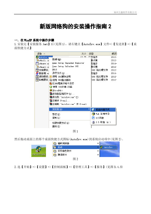
新版网络狗的安装操作指南2一.在WinXP系统中操作步骤1.安装完【安装服务.bat】后(见图1),请右键点【AutoSrv.exe】文件->【发送到】->【桌面快捷方式】图1然后拖动桌面上的那个桌面快捷方式图标(AutoSrv.exe)到系统启动项中(见图2)。
图22.选【开始】->【设置】->【控制面板】->【管理工具】->【服务】(见图3,4,5)图3图4找到“EliteIV Net Service (wuxing)”这项,选菜单【操作】->【属性】。
(见图6)在【常规】页中启动类型设置为【自动】(见图7)图7在【登录】页中勾选【允许服务与桌面交互】(见图8)图8在【恢复】页中【第一次失败】、【第二次失败】、【后续失败】设置为【重新启动服务】。
然后点【应用]和【确定】(见图9)图93.请不要把网络狗插在电脑机箱前面的USB插口中,机子启动时有可能电压不稳造成服务程序不能随系统启动,请把网络狗插在机箱后面的USB插口中。
二.在Windows7系统中操作步骤1.先右键选择【AutoSrv.exe】文件->【属性】,在【兼容性】页中勾选“以兼容模式运行这个程序”。
(见图10)图102.在【控制面板】中选【用户账户】(见图11)图11选择你登录的账户,选择【更改用户账户控制设置】(见图12)图12把通知项设为最低(见图13)图132.按WinXP中的设置一样,把AutoSrv.exe发送到桌面快捷方式,再把快捷方式拖到启动项中,然后【控制面板】->【管理工具】->【服务】,设置启动类型为【自动】, 勾选【允许服务与桌面交互】,【第一次失败】、【第二次失败】、【后续失败】设置为【重新启动服务】。
然后点【应用]和【确定】。
3. 请不要把网络狗插在电脑机箱前面的USB插口中,机子启动时有可能电压不稳造成服务程序不能随系统启动,请把网络狗插在机箱后面的USB插口中。

P/N: 1802054000316 *1802054000316*NPort 5400 Series Quick Installation GuideVersion 7.3, April 2021Technical Support Contact Information/support2021 Moxa Inc. All rights reserved.OverviewWelcome to Moxa’s NPort 5400 Series, a 4 port communication device that allows you to control RS-232 (for NPort 5410), RS-422/485 (for NPort 5430/5430I) or RS-232/422/485 (for NPort 5450/5450I) serial devices over a TCP/IP based Ethernet. Besides, NPort 5450-T and NPort 5450I-T are designed to use in wide temperature environment.NPort 5400 Series is a Moxa Green Product. Moxa’s Green Products satisfy the RoHS directive of the European Parliament, and accordingly, do not contain cadmium and cadmium compounds, hexavalent chromium compounds, lead and lead compounds, mercury and mercury compounds, PBBs (polybrominated biphenyls), or PBDEs (polybrominated diphenyl ethers).Package ChecklistBefore installing NPort 5400, verify that the package contains the following items:• 1 NPort 5400 4-port Serial Device Server•Power adapter (Sold separately for the NPort 5450-T and 5450I-T) •Power jack to 3-pin terminal block adapter•Wall mount kit•Quick Installation Guide•Warranty cardOptional Accessories•DK-35A For 35 mm DIN-Rail; includes 4 screwsNOTE Notify your sales representative if any of the above items is missing or damaged.NOTE The operating temperature of the power adapter (if applicable) in the box is from 0 to 40°C. If your application is out of thisrange, please use a power adapter supplied by UL ListedExternal Power Supply. (The power output meets SELV and LPSand is rated 12 to 48 VDC; the minimum current is 92.4 mA).Hardware IntroductionAs shown in the following figures, NPort 5410 has 4 Male DB9 ports, for the RS-232 interface, NPort 5430/5430I has 4 5-pin terminal blocks, for the RS-422/485 interface, and NPort 5450/5450I has 4 Male DB9 ports, for the RS-232/422/485 interface.NPort 5410/5450/5450INPort 5430/5430INPort 5450-T/5450I-TReset Button —Press the Reset button continuously for 5 sec to load factory defaults: Use a pointed object, such as a straightened paper clip or toothpick, to press the reset button. This will cause the Ready LED to blink on and off. The factory defaults will be loaded once the Ready LED stops blinking (after about 5 seconds). At this point, you should release the reset button.LED Indicators —NPort 5400’s top panel contains six LED indicators, as described in the following table.LED NameLED Color LED FunctionReady RedSteady on: Power is on and NPort is booting up.Blinking: Indicates an IP conflict, or DHCP or BOOTP server did not respond properly.GreenSteady on: Power is on and NPort is functioningnormally.Blinking: The NPort has been located by NPort Administrator’s Location functionOff Power is off, or power error condition exists. Ethernet Orange 10 Mbps Ethernet connection.Green 100 Mbps Ethernet connection.Off Ethernet cable is disconnected, or has a short. P1, P2, P3, P4 Orange Serial port is receiving data.Green Serial port is transmitting data. OffNo data is being transmitted or receivedthrough the serial port.LCM Display Panel (not support in -T model)—When the NPort 5400 unit is powered up, you will a see a display similar to:N P 5 4 1 0 _ 6 1 4 0 51 92 . 1 6 8 . 1 2 7 . 2 5 4 This is where NP5410_61405 is the server’s name, and192.168.127.254 is the server’s IP address.LCM Panel Operation (not support in -T model)—There are four buttons on NPort 5400’s top panel used to operate the server’s LCM panel. Going from left to right, the buttons are:Button ActionMENU Activates the main menu, or returns to a lower level.︿Scrolls up through a list of items shown on the LCM panel’s second line.﹀Scrolls down through a list of items shown on the LCM panel’s second line.SEL Selects the option listed on the LCM panel’s second line. Detailed LCM Panel Operating instructions can be found on the CD-ROM in the “NPort 5400 Series User’s Manual.”Hardware Installation ProcedureSTEP 1: After removing NPort 5400 from the box, the first thing you should do is attach the power adaptor.STEP 2: Connect NPort 5400 to a network. Use a standard straight-through Ethernet cable to connect to a Hub or Switch. When setting up or testing NPort 5400, you might find it convenient to connect directly to your computer’s Ethernet port. In this case, use a cross-over Ethernet cable.STEP 3: Connect NPort 5400’s serial port to a serial device.STEP 4: Placement OptionsWall or Cabinet MountingThe NPort 5400 comes with two metal attachment plates for attaching the NPort 5400 to a wall or the inside of a cabinet. First, use two screws per bracket to attach the brackets to the rear of the NPort5400. Next, use twoscrews per bracket to attach the NPort 5400 to a wallor cabinet.The heads of the screws should be less than 6.0 mmin diameter, and the shafts should be less than 3.5mm in diameter, as shown by the figure at the right.DIN-Rail MountingDIN-rail attachments can be purchased separately to attach the product to a DIN-rail. When snapping the attachments to the DIN-rail, make sure that the stiff metal springs are at the top.Wall Mount DIN-RailPull High/low Resistors Setting for the RS-485 PortDIP switches on the bottom of NPort 5400 are used to set the pull high/low resistor values for each serial port.Pull High/low Resistors for the RS-485 PortSW 1 2 3Pull High Pull Low TerminatorON 1KΩ 1KΩ120ΩDefault OFF150KΩ150KΩ–NOTE The operating temperature of the power adapter in the box is from 0 to 40°C. If your application is out of this range, please use a power adapter supplied by UL Listed External PowerSupply (The power output meets SELV and LPS and rated 12 - 48 VDC, minimum current 0.73 A). Moxa has power adapters with wide temperature range (-40 to 75°C, -40 to 167°F), the PWR-12150-(plug type)-SA-T series, for your reference.Software Installation InformationFor the NPort’s configuration, the default IP address of the NPort is: LAN: Static IP = 192.168.127.254; netmask = 255.255.255.0You may log in with the default account and password (account: admin ; password: moxa ) to change any settings to meet your network topology (e.g., IP address) or serial device (e.g., serial parameters). If you would like to apply the Real COM mode to your application, you will need to install NPort’s driver on your desktop. You may also refer to Moxa support websitehttps:///support/ for the user’s manual, driver, the Device Search Utility (DSU), and more.NOTE For the NPort with DB Male serial ports, you may refer to the DB9 Male Ports pin assignment section to loop back pin 2 andpin 3 for the RS-232 interface to carry out a self test on thedevice.Pin Assignments and Cable WiringDB9 Male Port PinoutsPin assignments apply to NPort 5410 (RS-232 only), 5450, and 5450I.DB9 MalePin RS-232 RS-422/4-wire RS-485 2-wire RS-4851 DCD TxD-(A) –2 RxD TxD+(B) –3 TxD RxD+(B) Data+(B)4 DTR RxD-(A) Data-(A)5 GND GND GND6 DSR – –7 RTS – –8 CTS – –9 – – – DB9 Wiring-NPort 5410/5450/5450IDB9 Female to DB9 MaleDB9 Female to DB25 MaleTerminal Block Wiring- NPort 5430/5430IEnvironmental SpecificationsPower requirementsInput Voltage12 to 48VDC Power Consumption: NPort 5410 NPort 5430 NPort 5430I NPort 5450 NPort 5450I350 mA @ 12 V, 190 mA @ 24 V 320 mA @ 12 V, 175 mA @ 24 V 530 mA @ 12 V, 280 mA @ 24 V 350 mA @ 12 V, 190 mA @ 24 V 554 mA @ 12 V, 294 mA @ 24 VOperating temp. Standard Models 0 to 55°C (32 to 131°F) Wide Temp. Models -40 to 75°C (-40 to 167°F) Operating humidity 5 to 95% RHDimensions (W×D×H) 158 × 33 × 103 mm 6.22 × 1.3 × 4.06 inSerial line protectionSurge: Power: 1 kV; Signal: 1 kV; 2 KV isolation protection (NPort 5430I/5450I models)Magnetic isolation 1.5 KV for EthernetPower line protection Level 3 Burst (EFT), EN 61000-4-4 Level 3 Surge, EN 61000-4-5Regulatory approvalsFCC Class A, CE Class A, UL, DNV (for DC input only), LVD, comply to EN 55011: 2007+A2: 2007 Class A (Group 1) and EN 60601-1-2: 2007。
版权声明是深圳市吉祥腾达科技有限公司注册商标。
文中提及到的其它商标或商品名称均是他们所属公司的商标或注册商标。
本产品的所有部分,包括配件和软件,其版权属深圳市吉祥腾达科技有限公司所有,在未经过深圳市吉祥腾达科技有限公司许可的情况下,不得任意拷贝、抄袭、仿制或翻译成其它语言。
本手册中的所有图片和产品规格参数仅供参考,随着软件或硬件的升级会略有差异,如有变更,恕不另行通知,如需了解更多产品信息,请浏览我们公司网站:目录第一章产品简介 (1)1.1 产品特性 (1)1.2 产品应用 (2)1.3 安全警示 (3)1.4 指示灯描述 (3)1.5 物品清单 (3)第二章安装指南 (4)第三章客户端应用程序使用 (9)3.1 Station Mode (客户端模式) (10)3.2 AP Mode (17)附录 (22)附录一:相关技术名词解释 (22)附录二:产品规格 (24)附录三:设置PSP (25)第一章产品简介W541U V2.0无线USB网卡支持IEEE 802.11g、IEEE 802.11b标准,无线传输速率高达54Mbps。
W541U V2.0支持WPS一键加密功能,轻松保障您的无线网络安全;支持Soft AP 功能,方便您快速组建无线局域网;支持PSP、WII、NDS连接Internet及Xlink Kai,让您享受联网对战的乐趣;支持中文SSID,方便接入各种无线网络;真正支持WMM,让您的语音视频更流畅。
总之,W541U V2.0是一款信号好、传输距离远、性能稳定、性价比极高的11G无线网卡。
1.1产品特性●符合IEEE 802.11g、IEEE 802.11b标准;●提供USB2.0接口;●最大传输速度可达54Mbps;●自动侦测网络及变换传输速率;●提供两种工作模式:集中控制式(Infrastructure)和对等式(Ad-Hoc);●支持Soft AP功能,方便您快速组建无线局域网;●支持PSP、WII、NDS连接Internet及Xlink Kai,让您享受联网对战的乐趣;●支持64/128位WEP数据加密;支持WPA/WPA2等加密方式;●支持WPS一键加密功能,使您无须再记录烦琐的密码;●真正支持WMM,让您的语音视频更流畅;●支持中文SSID,更方便您的使用;1.2产品应用54M 无线网卡为无线访问提供快速、可靠、低成本的解决方法。
NETGEAR路由器设置以及快速安装指南第一章将MR814接入网络产品图示MR81411M无线宽带路由器与Cable/DSL连接图示与Cable/DSL连接图示TOP第二章进入 MR814 的配置界面在完成了MR814与电脑的连接后,开始进行MR814的配置,首先要通过与MR814连接的电脑进入MR814。
下面首先配置与MR814连接的电脑,使其与MR814相连的网卡配置为自动获取IP地址。
以下以windows XP 操作系统为例来说明电脑的配置过程:A.单击“网络邻居”按右键,在弹出的菜单中选“属性”,单击“本地连接”按右键,在弹出的菜单中选“属性”,然后在“此连接使用下列项目”中选中“Internet协议(TCP/IP)”,最后点击“属性”。
如图:图2-1连接属性B.在新弹出的框图中将电脑的IP地址设为“自动获得IP地址”,然后“确定”,如下图:图2-2自动获得IP地址C.在Internet Explorer或者Netscape Navigator浏览器的地址栏键入http://192.168.0.1以连接路由器(MR814出厂IP地址是192.168.0.1):图2-3 输入MR814管理IP地址D.出于安全需要,路由器有自己的用户名和密码。
一旦连接成功会弹出如下登录提示,输入路由器用户名:admin,以及密码:password,都是小写:图2-4 登录MR814这里特别要说明的是,在实际操作中,往往会出现这种情况——在IE中输入了路由器的IP并回车后没有路由器的登录提示(图2-3 登录MR814)弹出。
出现这一现象极有可能是您的电脑没有获得与路由器在同一网段的IP地址。
因为MR814具有给连接到它的LAN口的电脑自动分配IP的功能,前面的将您的电脑设置为自动获得IP的目的即在于让它从路由器那里得到一个与路由器同一网段的IP地址,以便电脑能访问路由器。
您可以通过以下的操作确认电脑是否获得了IP,并可了解到如果没有获得IP该如何解决这一问题。
MERCURY54M无线宽带路由器怎么安装?
你检查下是否已经把你电脑的本地连接IP设置成
192.168.1.2-192.168.1.255之间的任意IP.
电脑IP必须和路由器在同一IP段才能进入192.168.1.1 里设置
第一个问题:无线路由器安装使用
1)用一根直通双绞线一头插入到无线路由器的其中一个LAN交换端口上(注意:不是WAN端口),另一头插入到一台计算机的有线网卡接口上。
2)连接并插上无线路由器、计算机电源,开启计算机进入系统。
在IE浏览器地址栏中输入厂家配置的无线路由器IP地址:192.168.1.1。
首先打开的是如下图所示的身份验证对话框。
进入后按说明书设置好无线路由器。
一般都有设
置向导。
3)把ADSL以前连接电脑的一端改插到无线路由器上就可以使用了。
第二个问题:无线路由器设置密码有2个方法
1> 进入路由器设置界面选择: 无线参数-基本设置--密钥选择: 密钥1, 密钥内容
里面设置10位输入密码. 并保存。
2> 直接设置允许使用的无线MAC。
点开始菜单,运行cmd,然后输入ipconfig/all,回车,就会出现你电脑的MAC,把那个无线mac记下来(例如:00-0B-DB-17-DA-CA)然后进入路由器设置:然后点无线设置,点访问设置,然后将无线访问控制模式选择为允许MAC列表,然后把你电脑的无线MAC输入进去,点提交!就OK了。
要把每台上网的电脑
的MAC都添加进去。
优美设计成就美好生活
1。
目录第一章产品简介 (2)1.1 产品特性 (2)1.2 产品应用 (3)1.3 物品清单 (3)第二章安装指南 (4)第三章无线网卡配置软件的使用 (7)3.1 网络状态 (7)3.2 网络扫描 (8)3.3 统计数据 (9)3.4 加密 (9)3.5 信息 (10)3.6 配置文件 (11)附录一 (13)附录二 (15)附录三 (16)第一章产品简介TWL542U 54M无线USB网卡适用于标准的USB1.1/2.0接口,支持最新IEEE802.11g/b无线通讯标准;支持WEP加密技术及最新WPA加密协议,使您的网络更安全;并具有无线漫游功能,可在不同的AP间移动,更具灵活性;即插即用,方便安装,支持所有WINDOWS系列操作系统。
1.1 产品特性提供USB1.1/2.0标准接口,即插即用,安装方便;完全兼容IEEE802.11g,IEEE802.11b标准;支持TCP/IP、NDIS、NetBEUI通讯协议;支持64/128位WEP加密、WPA-PSK等加密安全认证协议;最大传输速度可达54Mbps,自适应54/48/36/24/18/12/9/6/11/5.5/2/1Mbps;内置高增益天线;支持两种工作模式:Ad Hoc Mode(点对点)和Infrastructure Mode(基础架构);支持Windows98/me、Windows2000和XP等操作系统;提供简单的配置、监控应用软件;具有无线漫游功能,可在不同的AP间移动,且网络连接不中断;室内最远距离100米,室外最远300米(实际距离因环境而异);采用DSSS展频技术,并支持点对点到多点访问,与有线以太网实现无缝连接;轻松安装与设定,方便快捷低耗电,具有电源管理功能;指示灯描述:常亮表示网卡处于唤醒状态,闪烁表示网卡与接入点已连接;1.2 产品应用54M USB无线网卡为无线访问提供快速、可靠、低成本的解决方法。
具体应用如下:1、那些想在企业里有更强移动性的工作人员,他们希望在公司内部的任意地方都能访问传统的有线或无线网络;2、那些要求某个区域或整个场所的局域网布线要能经常改变的企业、个人;3、由于建筑或预算的限制,那些不适合进行局域网布线的公司,比如历史古建筑物、租用地或是临时地点;4、避免使用昂贵的电缆线、租用线路或者通行权的公司、个人。
EWEW-NET542
1 主板构造图
1
eWare 亿威工控
2 主板功能接口图
2
EWEW-NET542
3 跳线
下面是本主板各个跳线的说明: 位置
J1 J13 J35
功能
清除或保存 CMOS 参数 板载 FLASH 芯片的主从模式 选择 复位开关
●
J1: 清除或建立 CMOS 参数
将 J1 的 1-2 脚短接,可将需要的参数保存到 CMOS RAM 中,将 J1 的 2-3 脚短接可清除 CMOS 的数据。
缺省为 1-2 脚短接。
J1
1~2
功能描述
2~3
保存参数
清除 CMOS
3
eWare 亿威工控 J13: CF 卡主从模式选择
●
这个跳线用于 CF 卡的主从模式选择。
1-2 脚断开时,CF 卡处于 将 从模式状态;将 1-2 脚短接时,CF 卡处于主模式状态.缺省设置为短 接。
J13
1~2 断开
功能描述
1~2 短接
从模式
主模式
●
J35: 复位开关
将该跳线的两脚短接时,系统将会复位。
4
EWEW-NET542
4 接口
本主板上设计了多个接口,用以连接外设和扩展系统。
下面列出主板 上所有的接口:
连接器 J2 J5 J6 J7,J8 J9 J11 J19,J20,J21 J23 J25 J28 CN11 CN12 CN13
功能描述 +12V 电源接口 板载 USB 接口 CF 卡指示灯接口 COM1 & COM2 串行接口 PS/2 键盘/鼠标接口 +5V 电源接口 板载 RJ45 网络接口 VGA 显示接口 板载 RJ45 串行接口 电源指示灯接口 CF 卡插槽 PCI 转 90 插槽 TTL 电平输入输出接口
0
5
eWare 亿威工控 J5: USB 接口
●
本主板提供两组标准 USB 接口,可供用户连接 USB 设备。
●
J7,J8: 串行接口 J7,J8: J7,J8 J7, 功能描述
串口可根据需要连接鼠标器等输入 设备及调制解调器或数码相机等其 他设备使用。
下面列出一个串口的引脚定义: PIN 1 3 5 7 9 PIN NAME DCD RXD TXD DTR GND PIN 2 4 6 8 10 PIN NAME DSR RTS CTS RI NC
6
EWEW-NET542
●
键盘/鼠标接口 J9: PS/2 键盘/鼠标接口
J9
功能描述
PS/2 口可以接键盘和鼠标使用
PIN 1 3 5 7
PIN NAME KB DATA KB CLK GND VCC
PIN 2 4 6 8
PIN NAME MS DATA MS CLK GND VCC
7
eWare 亿威工控 J11: 电源接口
●
J11
功能描述
可提供+12V 和+5V 电源电压。
PIN
PIN NAME +5V GND GND +12V
1 2 3 4
●
J19,J20,J21: 板载 RJ45 网络接口 J19,J20 网络接口
主板上装有三个标准的 RJ45 网络接口。
8
EWEW-NET542
●
J23: VGA 显示接口
J23
功能描述
可以接 CRT 显示器
PIN 1 3 5 7 9 11 13 15
PIN NAME RED NC GND BLUE HSYNC +5V GND SCL
PIN 2 4 6 8 10 12 14 16
PIN NAME GND GREEN SDA GND NC VSYNC GND NC
9
eWare 亿威工控 串行接口 J25: 板载 RJ45 串行接口
●
J25
功能描述
这个串口采用 RJ45 接口的连接形 式。
PIN 1 3 5 7
PIN NAME RTS TXD GND DSR
PIN 2 4 6 8
PIN NAME DTR GND RXD CTS
●
CN11: CN11: CF 卡插槽
CN11 CF 卡插槽
功能描述
CN11 为 COMPACT FLASH CARD 插槽,用 户可将 CF 卡直接插入此插槽进行使用, 这个插槽装在主板的底层。
10
EWEW-NET542
PIN 1 2 3 4 5 6 7 8 9 10 11 12 13 14 15 16 17 18 19 20 21 22 23 24 25
PIN NAME GND IDEPDR3 IDEPDR4 IDEPDR5 IDEPDR6 IDEPDR7 IDEPCS0X GND GND GND GND GND +3.3V GND GND GND GND IDEPA2 IDEPA1 IDEPA0 IDEPDR0 IDEPDR1 IDEPDR2 WP NC
PIN 26 27 28 29 30 31 32 33 34 35 36 37 38 39 40 41 42 43 44 45 46 47 48 49 50
PIN NAME NC IDEPDR11 IDEPDR12 IDEPDR13 IDEPDR14 IDEPDR15 IDEPCS1X NC IOR IOW +3.3V PINTR +3.3V MODE SEL NC RESET PIORDY NC +3.3V LED NC IDEPDR8 IDEPDR9 IDEPDR10 GND
11
eWare 亿威工控 CN12: PCI 转 900 插槽
●
CN12
功能描述
这个插槽与常用的 PCI 直插槽的引脚 信号定义完全相同,只是外型上旋转 0 了 90 , 卡需沿平行于主板的方向 PCI 插入槽中,可以节省厚度方向上的空 间。
PIN A1 A2 A3 A4 A5 A6 A7 A8 A9 A10 A11
PIN NAME NC +12V NC NC +5V INTA# INTC# +5V NC +5V NC
PIN B1 B2 B3 B4 B5 B6 B7 B8 B9 B10 B11
PIN NAME NC NC GND NC +5V +5V INTB# INTD# NC NC NC
12
EWEW-NET542
A12 A13 A14 A15 A16 A17 A18 A19 A20 A21 A22 A23 A24 A25 A26 A27 A28 A29 A30 A31 A32 A33 A34 A35 A36 A37 A38 A39
GND GND RESV05 RST# +5V GNT GND PME# AD30 +3.3V AD28 AD26 GND AD24 IDSEL +3.3V AD22 AD20 GND AD18 AD16 +3.3V FRAME# GND TRDY# GND STOP# +3.3V
B12 B13 B14 B15 B16 B17 B18 B19 B20 B21 B22 B23 B24 B25 B26 B27 B28 B29 B30 B31 B32 B33 B34 B35 B36 B37 B38 B39
GND GND NC GND CLK GND REQ# +5V AD31 AD29 GND AD27 AD25 +3.3V C/BE#3 AD23 GND AD21 AD19 +3.3V AD17 C/BE#2 GND IRDY# +3.3V DEVSEL# GND LOCK#
13
eWare 亿威工控
A40 A41 A42 A43 A44 A45 A46 A47 A48 A49 A52 A53 A54 A55 A56 A57 A58 A59 A60 A61 A62 SDONE NC GND PAR AD15 +3.3V AD13 AD11 GND AD9 C/BE#0 +3.3V AD6 AD4 GND AD2 AD0 +5V REQ64# VCC VCC B40 B41 B42 B43 B44 B45 B46 B47 B48 B49 B52 B53 B54 B55 B56 B57 B58 B59 B60 B61 B62 PERR# +3.3V SERR# +3.3V C/BE#1 AD14 GND AD12 AD10 GND AD8 AD7 +3.3V AD5 AD3 GND AD1 +5V ACK64# +5V +5V
14
EWEW-NET542
●
电平输入输出接口 CN13: TTL 电平输入输出接口
CN13
功能描述
此接口有一路 TTL 电平输入,四路 TTL 电平输出。
PIN 1 3 5 7
PIN NAME TTLIN0 +5V +12V GND
PIN 2 4 6 8
PIN NAME TTLOUT0 TTLOUT1 TTLOUT2 TTLOUT3
15
。