自耦启动器说明书
- 格式:pdf
- 大小:400.32 KB
- 文档页数:3

济宁市市中区长城电器公司自耦减压起动柜使用说明书使用操作方法:一、自动操作合上电源开关,接通电源,红色指示灯亮。
将转换开关旋至“自动”位置,按“起动”按钮,起动接触器吸合,自耦减压变压器工作,电动机开始起动。
此时红灯熄灭,黄灯即亮,同时,电流——时间转换装置进入工作状态。
当电动机的转速接近同步转速时,电流——时间转换装置发出转换信号,电动机即投入正常运行。
此时,黄灯熄灭,绿灯亮,按“停止”按钮,电动机即停止工作。
二、手动操作合上刀开关,接通电源,红色指示灯亮。
将旋转开关旋至“手动”位置,按“起动”按钮,电动机开始起动。
此时,红灯熄灭,黄灯即亮。
待电动机转速接近同步转速时,即当电流表的指针逐渐下降到接近电动机的额定电流时,再按“运转”按钮,电动机即投入正常运行。
同时黄灯熄灭,绿灯即亮,按“停止”按钮,电动机即停止工作。
注意:(1)当从起动位置转换到运转位置时,为了避免过大的冲击电流或转矩,建议在电动机的起动电流接近额定工作电流时进行转换。
(2)在运行过程中,如热继电器发生误动作现象,此时应将热继电器的动作电流值适当调整大一点;如发生过载或断相动作,则应等到热继电器自动复位后,方能继续操作。
(3)在电动机起动中或运转后,只要按起动箱的的“停止”按钮,则启动箱就会断开电源,电动机停止工作。
(4)在进行手动操作时,工作人员务必要进行现场监控,不能忘记按“运转”按钮。
(5)起动柜起动过程中,变压器发热属正常现象,但温度不能超过120度。
由于连续数次起动或一次起动时间过长,温升过高时,温度保护器RJ2将切断控制电路,只有当自耦变压器温度降至温度保护器的额定复位温度值时,温度保护器复位,电路才能正常工作。
自耦变压器降压启动是指电动机启动时利用自耦变压器来降低加在电动机定子绕组上的启动电压。
待电动机启动后,再使电动机与自耦变压器脱离,从而在全压下正常运动。
这种降压启动分为手动控制和自动控制两种。
1.接线自耦变压器的高压边投入电网,低压边接至电动机,有几个不同电压比的分接头供选择。
2.特点设自耦变压器的变比为K,原边电压为U1,副边电压U2=U1/K,副边电流I2(即通过电动机定子绕组的线电流)也按正比减小。
又因为变压器原副边的电流关系I1=I2/K,可见原边的电流(即电源供给电动机的启动电流)比直接流过电动机定子绕组的要小,即此时电源供给电动机的启动电流为直接启动时1/K2 倍。
由于电压降低为1/K 倍,所以电动机的转矩也降为1/K2 倍。
自耦变压器副边有2~3 组抽头,如二次电压分别为原边电压的80%、60%、40%。
3.优点可以按允许的启动电流和所需的启动转矩来选择自耦变压器的不同抽头实现降压启动,而且不论电动机的定子绕组采用Y 或Δ接法都可以使用。
4. 缺点:设备体积大,投资较贵。
5.电动机自耦降压启动(自动控制电路)电动机自耦降压起动(自动控制)电路原理图上图是交流电动机自耦降压启动自动切换控制电路,自动切换靠时间继电器完成,用时间继电器切换能可靠地完成由启动到运行的转换过程,不会造成启动时间的长短不一的情况,也不会因启动时间长造成烧毁自耦变压器事故控制过程如下:1)合上空气开关QF接通三相电源。
2)按启动按钮SB2交流接触器KM1线圈通电吸合并自锁,其主触头闭合,将自耦变压器线圈接成星形,与此同时由于KM1辅助常开触点闭合,使得接触器KM2线圈通电吸合,KM2的主触头闭合由自耦变压器的低压低压抽头(例如65%)将三相电压的65%接入电动。
3)KM1辅助常开触点闭合,使时间继电器KT线圈通电,并按已整定好的时间开始计时,当时间到达后,KT的延时常开触点闭合,使中间继电器KA线圈通电吸合并自锁。
自耦变压器降压启动是指电动机启动时利用自耦变压器来降低加在电动机定子_ 绕组上的启动电压。
待电动机启动后,再使电动机与自耦变压器脱离,从而在全压下正常运动。
这种降压启动分为手动控制和自动控制两种。
1. 接线自耦变压器的高压边投入电网,低压边接至电动机,有几个不同电压比的分接头供选择。
2. 特点设自耦变压器的变比为K,原边电压为U1,副边电压U2=U1/K,副边电流I2 (即通过电动机定子绕组的线电流)也按正比减小。
又因为变压器原副边的电流关系I1=I2/K,可见原边的电流(即电源供给电动机的启动电流)比直接流过电动机定子绕组的要小,即此时电源供给电动机的启动电流为直接启动时1/K2倍。
由于电压降低为1/K倍,所以电动机的转矩也降为1/K2倍。
自耦变压器副边有2〜3组抽头,如二次电压分别为原边电压的80% 60% 40%3. 优点可以按允许的启动电流和所需的启动转矩来选择自耦变压器的不同抽头实现降压启动,而且不论电动机的定子绕组采用Y或△接法都可以使用。
4. 缺点:设备体积大,投资较贵。
5. 电动机自耦降压启动(自动控制电路)1----- 1|.1SB]E-/电动机自耦降压起动(自动控制)电路原理图7 H B上图是交流电动机自耦降压启动自动切换控制电路,自动切换靠时间继电器完成,用时间继电器切换能可靠地完成由启动到运行的转换过程,不会造成启动时间的长短不一的情况,也不会因启动时间长造成烧毁自耦变压器事故控制过程如下:1)合上空气开关QF接通三相电源。
2)按启动按钮SB2交流接触器KM1线圈通电吸合并自锁,其主触头闭合,将自耦变压器线圈接成星形,与此同时由于KM1辅助常开触点闭合,使得接触器KM2线圈通电吸合,KM2的主触头闭合由自耦变压器的低压低压抽头(例如65%)将三相电压的65%接入电动。
3)KM1辅助常开触点闭合,使时间继电器KT线圈通电,并按已整定好的时间开始计时,当时间到达后,KT的延时常开触点闭合,使中间继电器KA线圈通电吸合并自锁。


XJ01系列自耦减压起动箱符合标准:GB/T14048.4产品安装使用前,请仔细阅读使用说明书,并妥善保管,以备查阅。
起动器额定功率(kW)多次起动的通电总时间(s )XJ01-14~30XJ01-40~75XJ01-90~115XJ01-135~300406080100-1-5、本产品对控制电动机的短路、相序不起保护作用。
注意1、在起动和运行过程中,如电动机保护器或热继电器发生误动作现象,此时应将动作电流调大。
如发生过载动作,电动机保护器或热继电器则需2分钟复位后,方能继续工作。
4、用户在使用本产品前必须认真阅读本说明书, 在明确本产品的原理特性、操作方法及注意事项等,方可操作本产品.6、用户在使用本产品时输入端需合理加装短路保护装置。
7、用户在使用本产品时在没有专业人员指导下不得随意调整其技术参数(整定电流、起动时间)。
3、本起动箱仅作长时间间歇起动之用,不适宜在频繁操作条件下之用, 但允许从冷态连续起动两次,起动时间不超过15秒,时间间隔为30秒,而进行再次起动前,应使自耦变压器冷却到周围空气温度,当数次起动时间超过规定时间(见表1)时,应使其充分冷却,时间不少于4小时。
2、在手动操作转换时,必须待电动机接近额定转速时进行从起动到运行的切换。
否则容易损坏交流接触器,对输配电网亦不利。
8. 在使用本产品过程中操作者不得中途离开(起动箱处于起动状态),待负载转到正常运行状态,仪表指示灯均显示正常,数分钟后操作者方可离开。
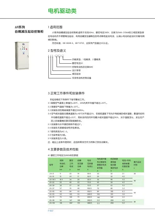
表 11 概述1.1 适用范围XJ01系列自耦减压起动箱适用于交流50Hz ,额定工作电压380V ,容量300kW 及以下三相鼠笼型感应式电动机作不频繁降压起动用。
广泛应用于冶金、石油、化工、矿山、建筑及环保等所有工业领域的电机传动设备。
产品结构简单、经济实用、操作简便,并具有过载、断相功能。
产品符合:GB /T14048.4 标准。
控制电动机的功率(最大)序号自耦变压器减压起动箱-2-1.3 型号含义:1.2.3 周围环境温度:-5~+40,24小时内平均温度不超过+35;1.2.7 额定绝缘电压为690V1.2.4 空气相对湿度在最高温度为+40时,不超过50%, 在较低温下允许有较高的相对湿度。
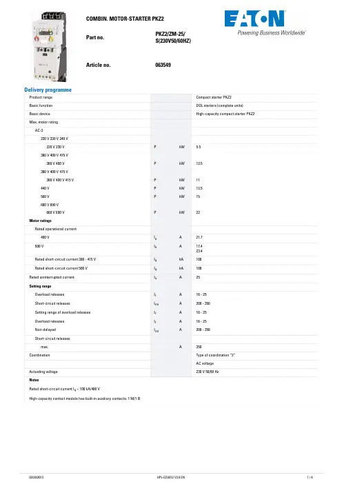
Eaton 197170Eaton Moeller® series EMS2 DOL starter, 230 V AC, 1,5 - 6,5 (AC-53a), 9 (AC-51) A, Screw terminalsGeneral specificationsEaton Moeller® series EMS2 DOLstarter1971704015080896111114.5 mm99 mm22.5 mm0.287 kgUL508IEC/EN 60947-4-2UL File No.: E29096UL Category Control No.: NLDX, NLDX7 UL 60947-4-1CSA-C22.2 No. 60947-4-1-14CE markingUL listedCertified by UL for use in CanadaUL report applies to both US and Canada EMS2-DO-Z-9-230VACProduct Name Catalog NumberEANProduct Length/Depth Product Height Product Width Product Weight Certifications Model CodeTemperature compensated overload protection DOL starting Motor protectionCLASS 10 ANoIP20 NEMA Other Direct starter Top-hat rail fixing (according to IEC/EN 60715, 35 mm) Rail mounting possible Motor feeder at bottom Vertical1.5 A9 AElectronic motor starter 0.2 - 2.5 mm², Main cables 0.14 - 2.5 mm², Control circuit cables 24 - 14, Main cables 26 - 14, Control circuit cables DOL starter (complete device)AC-25 °CClass A (EN 61000-6-3, emitted interference, radiated) EN 55011FunctionsClass Connection to SmartWire-DT Degree of protection Model Mounting methodMounting position Overload release current setting - min Overload release current setting - max Product category Terminal capacityTerminal capacity (AWG)TypeVoltage type Ambient operating temperature - min Radio interference class70 °C40 °C 80 °C 7 mA0 A4 mA85 - 253 V AC230 V (Actuating circuit ON, L, R) 230 V230 V0 V0 V0 V0 V9 A3 A6.5 A9 A6.5 A2 AAmbient operating temperature - maxAmbient storage temperature - min Ambient storage temperature - max Rated actuating current (Ic)Rated conditional short-circuit current (Iq), type 2, 380 V, 400 V, 415 VRated control supply current IsRated control supply voltageRated control voltage (Uc)Rated control supply voltage (Us) at AC, 50 Hz - minRated control supply voltage (Us) at AC, 50 Hz - maxRated control supply voltage (Us) at AC, 60 Hz - minRated control supply voltage (Us) at AC, 60 Hz - maxRated control supply voltage (Us) at DC - minRated control supply voltage (Us) at DC - maxRated operational current (Ie)Rated operational current (Ie) at AC-15, 220 V, 230 V, 240 V Rated operational current (Ie) at AC-3, 380 V, 400 V, 415 V Rated operational current (Ie) at AC-51Rated operational current (Ie) at AC-53A - maxRated operational current (Ie) at DC-13, 24 V1.5 kW3 kW3 kW42 - 550 V500 V AC0 - 44 V AC, Switching level "Low", Actuating circuit (ON, L, R) 85 - 253 V AC, Switching level "High", Actuating circuit (ON, L, R)11116.1 W0 W0 W9 A1 WIf necessary, Allow for deratingMeets the product standard's requirements.Meets the product standard's requirements.Meets the product standard's requirements.Meets the product standard's requirements.Meets the product standard's requirements.Does not apply, since the entire switchgear needs to be evaluated.Rated operational power at AC-3, 220/230 V, 50 HzRated operational power at AC-3, 380/400 V, 50 Hz Rated operational power at AC-53A, 380/400 V, 50 Hz Rated operational voltageSwitching level Number of auxiliary contacts (normally closed contacts) Number of auxiliary contacts (normally open contacts) Number of contacts (change-over contacts)Equipment heat dissipation, current-dependent PvidHeat dissipation capacity PdissHeat dissipation per pole, current-dependent PvidRated operational current for specified heat dissipation (In) Static heat dissipation, non-current-dependent PvsHeat dissipation details10.2.2 Corrosion resistance10.2.3.1 Verification of thermal stability of enclosures10.2.3.2 Verification of resistance of insulating materials to normal heat10.2.3.3 Resist. of insul. mat. to abnormal heat/fire by internal elect. effects10.2.4 Resistance to ultra-violet (UV) radiation10.2.5 LiftingDoes not apply, since the entire switchgear needs to be evaluated.Meets the product standard's requirements.Does not apply, since the entire switchgear needs to be evaluated.Meets the product standard's requirements.Does not apply, since the entire switchgear needs to be evaluated.Does not apply, since the entire switchgear needs to be evaluated.Is the panel builder's responsibility.Is the panel builder's responsibility.Is the panel builder's responsibility.Is the panel builder's responsibility.Is the panel builder's responsibility.The panel builder is responsible for the temperature rise calculation. Eaton will provide heat dissipation data for the devices.Is the panel builder's responsibility. The specifications for the switchgear must be observed.Is the panel builder's responsibility. The specifications for the switchgear must be observed.The device meets the requirements, provided the information in the instruction leaflet (IL) is observed.EMS 2 Electronic motor starters - brochureEMS 2 Electronic motor starters - flyerSwitching and protecting motors - catalogDA-DC-00004192.pdfDA-DC-00003980.pdfeaton-contactors-ems2-reversing-starter-characteristic-curve-002.eps eaton-contactors-ems2-reversing-starter-characteristic-curve.eps eaton-contactors-ems2-reversing-starter-characteristic-curve-004.epseaton-contactors-ems2-reversing-starter-dimensions-002.eps eaton-contactors-ems2-reversing-starter-3d-drawing-002.epsDA-CE-ETN.EMS2-DO-Z-9-230VACIL034064ZUEaton's electronic motor starter EMS2eaton-electronic-motor-starter-ems2-manual-mn034003en-us.pdfDA-CD-ems2_dos_ros_z_24_230vDA-CS-ems2_dos_ros_z_24_230v10.2.6 Mechanical impact10.2.7 Inscriptions10.3 Degree of protection of assemblies10.4 Clearances and creepage distances10.5 Protection against electric shock10.6 Incorporation of switching devices and components 10.7 Internal electrical circuits and connections10.8 Connections for external conductors10.9.2 Power-frequency electric strength10.9.3 Impulse withstand voltage10.9.4 Testing of enclosures made of insulating material 10.10 Temperature rise10.11 Short-circuit rating10.12 Electromagnetic compatibility10.13 Mechanical function BrochuresCatalogues Certification reports Characteristic curve DrawingseCAD model Installation instructions Installation videos Manuals and user guides mCAD modelEaton Corporation plc Eaton House30 Pembroke Road Dublin 4, Ireland © 2023 Eaton. All rights reserved. Eaton is a registered trademark.All other trademarks areproperty of their respectiveowners./socialmedia。
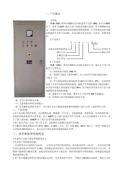
一、产品概述1.用途JJ1B(TG01)系列自耦降压启动柜适用于交流50HZ,电压为660V以下,容量315KW级以下的三相鼠笼型感应电机,作不频繁降压起动,以减少电动机起动电流对输电网络的影响,并可加速电动机至额定转速和人为停止电动机,对电动机具有过负荷、欠电压、短路等保护。
2.产品型号改型代号减压启动额定功率设计序号3.工作条件JJ1B(TG01)系列自耦降压启动柜安装在户内,保证在下列工作条件下正常运行。
(1)海拔高度不超过2000米;(2)周围空气温度上限为+40℃,24小时内平均值不超过+35℃,下限为-5℃(3)空气相对湿度在最高温度为+40℃时不超过50% ,在较低的温度下可允许有较高的相对温度,最湿月平均最低温度不超过+20℃,该月的平均最大相对湿度不超过90%,由于温度变化发生在产品上的凝露情况必须采取措施;(4)振幅不大于0.5毫米,频率不大于每分钟600次的振动;(5)安装面与水平面的倾斜不超过5度;(6)空气污染等级为3级;(7)无显著振动和冲击的地方;(8)在无爆炸危险的介质中,且介质中无足以腐蚀金属和破坏绝缘的气体与尘埃(包括导电尘埃).二、产品结构1.本产品为柜式防护结构,由自耦变压器、断路器(刀开关)、交流接触器、热继电器、电动机保护器、电流时间转换装置等元件组成。
对于00KW以上的产品带有无声节电器。
无声节电器装有主令开关,客人工投入或切除。
100KW以上的产品采用电动机保护器。
2.本产品有手动、自动二种工作方式,由转换开关惊醒自动或手动切换。
3.自耦变压器备有额定电压65%(60%)及80%二当头,出厂时接65%(60%)抽头上,如用户需要可自行改接到80%的抽头上,也可以在订货时说明需要接的抽头位置。
三、技术数据和性能特征1.本系列产品的主要技术数据见表1。
2.本系列产品的起动性能:启动柜每次启动时间≤15s时,一小时内允许均匀起动两次;每次起动时间﹤15s时,一小时内允许数次均匀连续起动时间综合为30s;达到规定起动时间后,再次启动前的冷却间隔时间不应少于2小时,否则将可能烧毁自耦变压器。
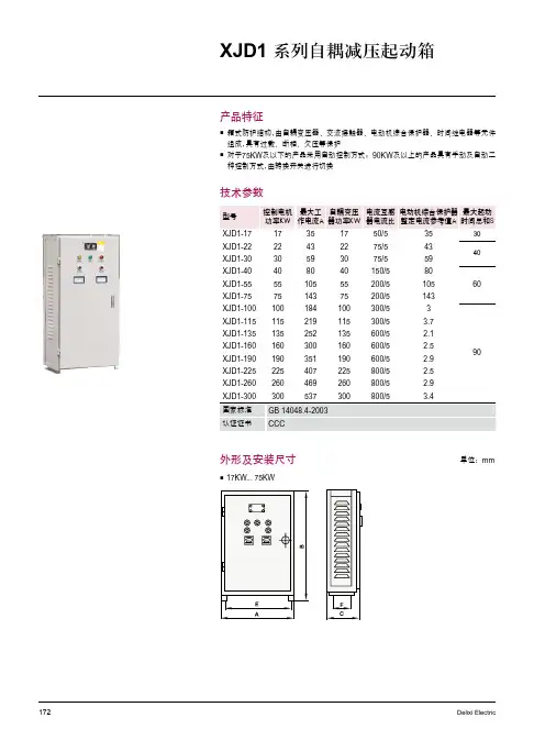
自耦减压起动箱概述1.用途:XJ01系列自耦减压起动箱适用于交流50HZ、额定电压380伏,容量300千瓦及以下的三相鼠笼型感应电动机不频繁降压起动用,利用自耦变压器降压,以减少电动机起动电流对输电网络的影响。
2.本型起动箱安装在户内,保证在下列工作条件下正常运行:1).海拔高度不超过2000米;2).周围介质温度不高于+40℃,不低于-5℃;3).空气相对湿度在最高温度为40℃,不超过50%;在最湿月(+25℃),不大于90%;4).污染等级为3级;5).安装条件:a.安装面与水平面的倾斜不超过5度;b.安装类别为Ⅱ、Ⅲ。
3.型号含义X J01起动箱减压自耦变压器起动性能电动机起动时,起动电流不超过额定电流的4倍,其最长起动时间为30秒(包括一次或连续起动时间的总和),若连续起动时间总和和已达30秒,则起动后的冷却时间,应不小于2小时才能再起动,因为本产品仅作长时间间歇起动之用,不适宜在频繁操作条件下使用。
起动箱具有过负荷及失压保护。
产品结构本产品为箱式防护结构,有自耦变压器、交流接触器、热继电器、时间继电器等元件组成,对于75千瓦及以下的产品,系采用自动控制方式,80千瓦以上的产品,采用手动和自动两种控制方式,可以自由调节控制启动时间,自耦变压器线圈备用额定电压65%及80%二个抽头,出厂时接在80%抽头上,电机接65%抽头时,起动转距为0.385Me,接80%抽头时,起动转距为0.64Me,Me为电机额定转距。
技术规格1.本产品的主要技术规格如表规定。
2.起动箱的热继电器整定值:(1)75KW及以下需整定在Ie值上;(2)100KW及以下需整定在Ie/K值上。
安装和使用1.本产品的电气原理图4—6。
图4图5图6 图7图82.本产品在安装完毕使用之前,必须按电气原理图复核接线是否有误,然后空载(不带电机),试验数次,检查电器元件是否动作可靠,确定可靠无误后,再进行负载试验,按电机的实际起动时间的要求,调整热继电器的动作电流,调试完毕,即可使用。
March 2008Starters — Interchangeable HeaterContentsDescription Page Product Family OverviewProduct Description. . . . . . .34-297 Features . . . . . . . . . . . . . . . .34-297 Standards andCertifications. . . . . . . . . . .34-297 InterchangeableHeater StartersProduct Description. . . . . . .34-306 Features . . . . . . . . . . . . . . . .34-306 Product Selection . . . . . . . .34-307 Accessories. . . . . . . . . . . . . . . .34-313 Auxiliary Contacts. . . . . . . .34-313 DC Magnet Coils . . . . . . . . .34-315 Renewal Parts. . . . . . . . . . . . . .34-320Note:For more information, seeCA03402001E.Product DescriptionNon-reversingIEC Freedom Series Starters utilize an Interchangeable Heater Pack Overload Relay which allows increased flexibil-ity. Starters are available to cover3-phase motors with fractional horse-power ratings up to 900 hp at 480V. ReversingThree-phase, full voltage magnetic starters are used primarily for revers-ing of 3-phase squirrel cage motors. They consist of two contactors and a single overload relay assembled together. The contactors are mechani-cally and electrically interlocked to pre-vent line shorts and energization of both contactors simultaneously.Features■EN60947-4-1 IEC 947-4-1 Compli-ance — International Standard forlow voltage switchgear and controldevices.■UL listed and CSA certified.■Bimetallic Ambient CompensatedOverload Relays — available inthree basic sizes covering applica-tions up to 200 hp (100 hp Revers-ing) — reducing number of differentcontactor/overload relay combina-tions that have to be stocked.These overload relays feature:❑Selectable Manual or AutomaticReset operation.❑Interchangeable Heater Packsadjustable ±24% to match motorFLA and calibrated for 1.0 and1.15 service factors. Heater packsfor smaller overload relay willmount in larger overload relay —useful in derating applicationssuch as jogging.❑Meets UL508 Single-Phasingrequirements, Class 20 or Class10 trip time.❑Overload trip indication.❑Electrically isolated NO-NC con-tacts (pull RESET button to test).■Long life twin break, silver cadmiumoxide contacts — provide excellentconductivity and superior resistanceto welding and arc erosion.■Designed to 2,000,000 electrical and20,000,000 mechanical operationsthrough 20 hp at 460V. Adequate formost general duty motor controlapplications.Non-reversing■Highest horsepower rating in com-pact, space-saving designs, 45 mmframe rated maximum 20 hp at460V, 65 mm frame rated maximum50 hp, 90 mm frame rated maximum100 hp, and 180 mm rated maxi-mum 200 hp.■IP20 finger protection shieldsavailable.■Contactor and terminal markingsconform to CENELEC EN50011.■One NO right-side mounted auxil-iary contact supplied as standard onSizes A – N (on Sizes A – C, contactoccupies 4th power pole — noincrease in width). Sizes P – S haveNO-NC.■45 mm open type starters, sizesA – F, have DIN rail or universal basemounting. DIN rail release mecha-nism conveniently located on lineside of starter. A steel mountingplate is optional.■65 mm starters, sizes G – K; 90 mmstarters, sizes L – N; and P – S180 mm supplied with steel mount-ing plate as standard.■Four basic starter frame widths —45 mm, 65 mm, 90 mm and 180 mm— simplifying panel layout.Reversing■Highest horsepower rating in com-pact, space-saving designs. 45 mmframe rated maximum 20 hp at460V, 65 mm frame rated maximum50 hp, and 90 mm frame rated maxi-mum 100 hp.■45 mm open type reversing starters,Sizes A – F, have DIN rail or univer-sal base mounting. DIN rail releasemechanisms conveniently locatedon line side of starters. A steelmounting plate is optional.■65 mm reversing starters, SizesG – K, and 90 mm reversing starters,Sizes L – N, are supplied with steelmounting plate as standard.■Sizes A – K have a wired NC topmounted electrical interlock on eachcontactor. Sizes L – N have one NO-NC side mounted electrical inter-lock on each contactor.■A full time of snap-on accessories —top and side mounted auxiliary con-tacts, solid-state and pneumatic tim-ers, etc.■Straight-through wiring — line lugsat top, load lugs at bottom.■Horizontal of vertical mountingon upright panel for applicationfreedom.■Screw type power terminals havecaptive, backed-out self-lifting pres-sure plates with ± screws — reduc-ing wiring time.IEC Size DCat. No. AE16DN0BCMarch 2008Starters — Interchangeable HeaterProduct SelectionWhen Ordering Specify■Select required starter by Catalog Number and replace the magnet coil alpha designation in the Catalog Num-ber (_) with the proper Code Suffix from T able 34-386 on Page 34-308.■Example: for a Size B starter with a 480V/60 Hz coil, order AE16BNS0CC.■For DC Magnet Coils , see Accesso-ries,Page 34-315.Table 34-383. Type AE16/AE56 Starters — Interchangeable Heater Overload Relay — 3-Pole — Non-reversing ᕃᕃIEC Sizes A – N, open are supplied with a NO auxiliary contact. On IEC Sizes A – C, the 4th power pole position is used as the auxiliary contact and adds no additional width. Open type Sizes A – K can be ordered with a top mounted auxiliary contact instead of a side mounted contact. To order, change the 7th digit of the listed Catalog Number from “S ” to “T ”. Example: AE16AN T 0AC. On open type Sizes A – K, if the NO auxiliary contact is notrequired, drop the “S ” from the listed Catalog Number. Example: AE16AN0AC. On IEC Sizes P – S, a NO-NC side mounted is standard. Sizes T – X have 2NO-2NC, Size Z has 2NO-1NC.Max. UL AC-3Ampere RatingIEC 947 AC-1Thermal Current 600V Maximum kW Rating Maximum UL Horsepower Catalog NumberPrice U.S. $3-Phase 1-Phase3-Phase 220V 380V 415/440V 500/550V 660V 115V 230V 208V 240V 480V 600V 7101218252020203232 1.11.52.245.5 2.245.57.511 2.245.57.51145.57.51115 1.52.245.57.51/41/21/2121/212331-1/223551-1/22357-1/2357-1/2101557-1/2101520AE16ANS0_C AE16BNS0_C AE16CNS0_C AE16DNS0_C AE16ENS0_C 323744607332506075807.5—111518.51518.52230371518.522303718.52230303710111518.52223355557-1/210107-1/27-1/2101520101015202520253040502530404050AE16FNS0_C AE16GNS0_B AE16HNS0_B AE16JNS0_B AE16KNS0_B 851051401702003001001351751852203152230374555904555759011016045557590110160557590901101603745454555757-1/21010———101010———2530405060753040506075100607510012515020075100125125150200AE16LN0_AE16MN0_AE16NN0_AE16PN0_AE16RN0_AE16SN0_45055063070086012156007601000100011001350129160220220270380220280375375475650240315————300375500500600840300375500500600840————————————125150150200250450125150200250300450250350400500600900250350400500600900AE16TN0_AE16UN0_AE16VN0_AE16WN0_AE16XN0_AE16ZN0_Accessories. . . . . . . . . . . . . Pages 34-313 – 34-319Discount Symbol. . . . . . . . . 1CD7March 2008Starters — Interchangeable HeaterWhen Ordering Specify■Select required starter by Catalog Number and replace the magnet coil alpha designation in the CatalogNumber (_) with the proper CodeSuffix from Table 34-386 below.■Example: for a Size B starter with a 480V/60 Hz coil, order AE16BNS0CC.■For DC Magnet Coils, see Accesso-ries,Page 34-315.Table 34-384. Type AE16/AE56 Starters — Interchangeable Heater Overload Relay — 3-Pole — ReversingᕃᕃSizes A – K IEC starters do not include holding circuit contacts. For factory installed NO auxiliary contacts, insert “S” (side mounted) or “T” (top mounted) after 6th digit of listed Catalog Number. Example: Change AE56AN0AC to AE56AN S0AC. For “T”, top mounted NC contact blocks are replaced with NO-NC blocks — for “S”, they are replaced with NO-NC side mounted blocks.Table 34-385. Maximum Horsepower Ratingof Starters for 380V 50 Hz ApplicationTable 34-386. AC Coil SuffixesᕄIEC Sizes A – F only.ᕅIEC Sizes A – F only. Sizes G – V are24/60 only. For DC Magnet Coils, see Accessories on Page 34-315.IEC Size FCat. No. AE56DN0BC IEC Size GCat. No. AE56GN0BBMax. UL AC-3 Ampere Rating IEC 947 AC-1ThermalCurrent600VMaximum kW Rating Maximum UL Horsepower CatalogNumberPriceU.S. $ 3-Phase1-Phase3-Phase220V380V415/440V500/550V660V115V230V208V240V480V600V7 10 12 18 2520202032321.11.52.245.52.245.57.5112.245.57.51145.57.511151.52.245.57.51/41/21/2121/212331-1/223551-1/22357-1/2357-1/2101557-1/2101520AE56AN0_CAE56BN0_CAE56CN0_CAE56DN0_CAE56EN0_C32 37 44 60 7332506075807.5—111518.51518.52230371518.522303718.52230303710111518.52223355557-1/210107-1/27-1/2101520101015202520253040502530404050AE56FN0_CAE56GN0_BAE56HN0_BAE56JN0_BAE56KN0_B85 105 1401001351752230374555754555755575903745457-1/21010101010253040304050607510075100125AE56LN0_AE56MN0_AE56NN0_IEC Size A B C D E F G H hp3551010152025IEC Size J K L M N P R S hp3040506075100125150Coil Volts and Hertz Code Suffix120/60 or 110/50240/60 or 220/50480/60 or 440/50600/60 or 550/50208/60ABCDE277/60208-240/60ᕄ240/50380-415/50550/50HJKLN24/60, 24/50 ᕅ24/5032/5048/6048/50TUVWYAccessories . . . . . . . . . . . . . Pages 34-313 – 34-319Discount Symbol . . . . . . . . . 1CD7。
TH2-215-400kw自耦减压综合启动控制柜使用说明书韶关市全成工业科技有限公司2015年1月TH2-215-400Kw自耦减压综合启动控制柜使用说明书韶关市全成工业科技有限公司目录一、操作步骤 (1)(一)、启动前检查 (1)(二)、首次起动 (2)(三)、起动 (3)(四)、停机 (7)二、进线接线电缆表 (8)三、电气原理图 (10)四、电缆连接框图 (18)五、产品试验记录 (19)2TH2-215-400kw自耦减压综合启动控制柜使用说明书请在使用本控制柜前认真阅读本使用说明书,按照电气原理图将设备主电机、稀油站与控制柜正确连接。
注:所有连接电缆长度超过50米应适当加粗。
控制柜通电前必须连接地线,接地必须良好,所有电线电缆做好防护措施。
一、操作步骤(一)、启动前检查(一)、请确认电源电压。
(二)、请确认电机及控制线连接正确及牢固。
检查加固控制柜元器件的螺丝,防止运输颠簸造成的螺丝松动,引起接触不良。
(三)、请确认油位在油尺指示器中间。
(四)、请确认每台油泵供油阀门已打开。
(五)、请确认正常压力控制器[PY1]设定动作压力:0.1MPa(六)、请确认低压力控制器[PY2]设定动作压力:0.05MPa(七)、请确认油箱温度控制器[TY1]设定工作温度(21-27)度,允许启动温度16度。
SV:27,滞后(回差)HYS:6,报警AL1:16。
(八)、请确认供油温度控制器[TY2]设定工作温度(45-35)度,超温报警温度54度。
SV:45,滞后(回差)HYS:10,报警AL1:54。
(九)、请确认测试报警[SB1]及消音[SB2]按钮正常工作。
(十)、请确认主电机的启动时间[KT1],出厂设定为18秒。
(十一)、请确认油箱温度测量的铂热电阻[PT1]及供油温度测量的铂热电阻[PT2]接线牢固。
(二)、首次起动1.合上低压断路器[QM4],检查油箱温度仪表[TY1]是否高于16度,低于16度需要按下加热按钮[SM4],接触器[KM4]闭合,启动油箱加热,油箱加热温度至27度后,自动停止加热。