Kinetix 运动控制选型指南
- 格式:pdf
- 大小:9.33 MB
- 文档页数:96

Kinetix 5500 伺服驱动器产品目录号 2198-H003-ERS、2198-H008-ERS、2198-H015-ERS、2198-H025-ERS、2198-H040-ERS、2198-H070-ERS、2198-H003-ERS2、2198-H008-ERS2、2198-H015-ERS2、2198-H025-ERS2、2198-H040-ERS2、2198-H070-ERS2、2198-CAPMOD-1300本手册链接到 Kinetix 5500 Servo Drive Fault Codes Reference Data (出版号: 2198-RD005),以供故障代码查询。
可下载电子表格,以便离线访问。
2罗克⻙尔⾃动化出版物 2198-UM001L-ZH-P - 2022 年 2 月Kinetix 5500 伺服驱动器⽤⼾⼿册⽤⼾重要须知在安装、配置、操作或维护本产品之前,请阅读本文档以及“其他资源”章节所列的文档,了解关于安装、配置和操作该设备的信息。
除了所有适用的条例、法律和标准的要求之外,用⼾还必须熟悉安装和接线说明。
包括安装、调整、投⼊运⾏、使用、装配、拆卸和维护等在内操作必须由经过适当培训的⼈员根据适用的操作守则来执⾏。
如果未遵照制造商所指定的方式使用该设备,将可能导致该设备提供的保护失效。
在任何情况下,对于因使用或操作该设备造成的任何间接或连带损失,罗克⻙尔⾃动化公司概不负责。
本手册中包含的示例和图表仅用于说明。
由于任何具体安装都涉及众多变数和要求,罗克⻙尔⾃动化公司对于依据这些示例和图表所进⾏的实际应用不承担任何责任和义务。
对于因使用本手册中所述信息、电路、设备或软件而引起的专利问题,罗克⻙尔⾃动化公司不承担任何责任。
未经罗克⻙尔⾃动化公司的书⾯许可,不得复制本手册的全部或部分内容。
在整本手册中,我们在必要的地方使用了以下注释,来提醒您留意安全注意事项。
设备表⾯或内部还可能贴有以下标签,而标签上给出了具体的预防措施。

Kinetix 6000 多轴伺服驱动器目录号2094-ACxx-Mxx-S 、2094-BCxx-Mxx-S 、2094-AMxx-S 、2094-BMxx-S2094-ACxx-Mxx 、2094-BCxx-Mxx 、2094-AMxx 、2094-BMxx 、2094-BSP2、2094-PRF 、2094-SEPM-B24-S用户手册重要用户信息在安装、配置、操作或维护本产品之前,请仔细阅读本文档及“其他资源”部分所列文档中有关安装、配置和操作此设备的信息。
除遵守所有适用的规程、法律及标准的要求外,用户还应熟悉安装 和接线说明。
安装 、 调节 、 投入使用 、 操作 、 装配 、 拆卸和维护等活动均要求由经过适当培训的人员遵照适 用法规执行。
如果未按制造商指定的方式使用设备,则设备提供的保护功能可能会受到影响。
任何情况下,对于因使用或操作本设备造成的任何间接损失或连带损失,罗克韦尔自动化公司概不负责。
本手册中包含的示例和图表仅用于说明。
由于任何特定的安装都存在很多差异和要求,罗克韦尔 自动化对于依据这些示例和图表所进行的实际应用不承担任何责任和义务。
因使用本手册中所述的信息、电路、设备或软件而引起的相关专利问题,罗克韦尔自动化公司不负任何责任。
未经罗克韦尔自动化公司的书面许可,不得复制本手册的全部或部分内容。
在整本手册中,我们在必要的地方使用了注释,来提醒您注意相关的安全事宜。
设备表面或内部也可能贴有标签,以提供特定的预防措施。
Allen-Bradley 、CompactLogix 、ControlFLASH 、ControlLogix 、DriveExplorer 、Guardmaster 、HPK-Series 、Integrated Architecture 、Kinetix 、LDC-Series 、LDL-Series 、Logix5000、MP-Series 、RDD-Series 、Rockwell Automation 、Rockwell Software 、RSLinx 、RSLogix 、SCANport 、SoftLogix 、Studio 5000 Logix Designer 、Studio 5000 和 TL-Series 是罗克韦尔自动化公司的商标。
技术园地-Kinetix集成运动控制入门伺服系统主要解决对象的位置控制问题,实现执行机构对位置指令的准确跟踪。
它是在应用领域非常广泛的一类系统,典型实例有:机械加工过程中机床定位控制和加工轨迹控制;冶金工业中轧钢机压下装置及其辅助设备控制;仪表工业中各种记录仪的笔架控制;大规模集成电路所需的制图机、光刻机……集成运动控制系统K i n e t i x是罗克韦尔自动化革命性的重量级产品,它注重完整的运动控制解决方案,由C o n t r o l L o g i x,S E R C O S I n t e r f a c e,数字运动控制模块,伺服驱动器,电机以及执行机构组成,加上罗克韦尔自动化丰富的应用经验,使得一体化运动控制正在成为机械控制的新准则。
K i n e t i x的推出满足了用户们节省时间、提高产品吞吐量、灵活性的需求,它通过一台控制器和一个软件包(通过S E R C O S接口将控制器、电机和驱动器集成在一起),在任何场合都真正的把顺序控制和运动控制集为一体:传送、纸盒包装、缠绕、装瓶、标签……用户使用R S L o g i x5000在一个控制程序包中获得完整的运动组态和编程情况,内置运动指令使用户不再需要协调不同控制器间的接线或者不同控制器中独立的程序。
通过下面这个基础配置实验,让我们一起体验K i n e t i x带给我们的便捷感受!!第一步:启动R S L o g i x5000(V e r s i o n13.00),新建一个项目文件,并完成C o n t r o l l e r P r o p e r t i e s的基础配置。
提示:请在“D a t e/T i m e”分页中选中“M a k e t h i s c o n t r o l l e r t h eC o o r d i n a t e d S y s t e m T i m e M a s t e r”项。
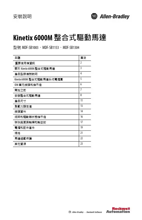
安裝說明Kinetix 6000M 整合式驅動馬達型號MDF-SB1003、MDF-SB1153、MDF-SB1304主題頁次重要使用者資訊2關於Kinetix 6000M 整合式驅動馬達3產品型錄編號說明4Kinetix 6000M整合式驅動馬達系統電纜圖5IDM 單元接頭和指示燈6開始之前7安裝整合式驅動馬達8產品尺寸11負載力額定值13接頭資料14網路和驅動器狀態指示燈16移除與更換軸鍵和軸密封17電纜和配件套件19規格21馬達過載保護22其他資源232 Kinetix 6000M 整合式驅動馬達洛克威爾自動化出版品編號 MDF-IN001B-ZC-P - 2013 年8月重要使用者資訊在您安裝、設定、操作或維護本產品之前,請參閱本文件以及列在其他資源段落的文件中關於本設備的安裝、組態與操作資訊。
使用者需要熟悉安裝與配線說明,以及所有適用的法規、法律和標準的規定。
安裝、調整、開始服務、使用、組裝、拆卸與維護等活動需要由受過適當訓練的人員遵照適用實施法規來進行。
如果沒有依照製造商指定的方式使用本設備,可能損及設備附帶的保護機制。
洛克威爾自動化公司對任何因為使用或應用本設備而造成的間接或隨之而來的損概不承擔任何責任。
本手冊中所含的範例及圖示僅為示範目的。
由於個別安裝會有許多不同的變數及條件,洛克威爾自動化公司無法對依照範例及圖示指示進行的實際使用狀況負責或提供賠償。
洛克威爾自動化公司對本手冊中所述之資訊、電路、設備或軟體的使用概不承擔任何專利責任。
在取得洛克威爾自動化公司書面同意之前,禁止重製本手冊的部分或全部內容。
在本手冊中,如有需要,我們會使用備註提醒您安全注意事項。
說明特定預防措施的標籤也可能會貼在設備上方或內部。
警告: 顯示可能會在危險環境中爆炸,造成人員受傷、死亡、財產損壞、經濟損失的情況之資訊。
注意事項: 顯示可能造成人員受傷、死亡、財產損壞、經濟損失的實務情況資訊。
注意事項有助於您發現、避免並瞭解危險的後果。
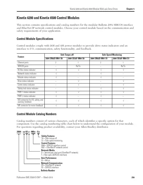
Kinetix 6200 and Kinetix 6500 Modular Multi-axis Servo Drives Chapter 5Kinetix 6200 and Kinetix 6500 Control ModulesThis section contains specifications and catalog numbers for the modular Bulletin 2094 SERCOS interface and EtherNet/IP network control modules. Choose your control module based on the communication and safety requirements of your application.Control Module SpecificationsControl modules couple with IAM and AM power modules to provide drive status indicators and an interface to I/O, communication, safety functionality, and feedback.Control Module Catalog NumbersCatalog numbers consist of various characters, each of which identifies a specific option for thatcomponent. Use the catalog numbering table chart below to understand the configuration of your module. For questions regarding product availability, contact your Allen-Bradley distributor.Feature Safe Torque-offSafe Speed Monitoring2094-EN02D-M01-S02094-SE02F-M00-S02094-EN02D-M01-S12094-SE02F-M00-S1Ethernet ports 2121SERCOS ports –Rx/Tx –Rx/Tx DC Bus status indicator √√√√Network status indicator √–√–Module status indicator √–√–Drive status indicator –√–√Comm status indicator –√–√Safety lock status indicator ––√√PORT 1 status indicator √√√√PORT 2 status indicator √–√–IOD connector for I/O, safety, and auxiliary feedback√√√√MF connector for motor feedback√√√√Axis Performance 02 = 500 µsBulletin NumberControl FeaturesM00 = SERCOS interface control M01 = EtherNet/IP network control Safety Features S0 = Safe torque-offS1 = Safe speed monitoring Network MediaD = Twisted pair, dual port (EtherNet/IP network)F = Fiber optic (SERCOS interface)Network Communication EN = EtherNet/IP network SE = SERCOS interfaceChapter 5Kinetix 6200 and Kinetix 6500 Modular Multi-axis Servo DrivesKinetix 6200 and Kinetix 6500 General System SpecificationsThis section contains environmental, weight, power dissipation, circuit breaker/fuse, transformer, and contactor specifications.Environmental SpecificationsWeight SpecificationsAttributeOperational Range Storage Range (nonoperating)Ambient temperature 0…50 °C (32…122 °F)-40…70 °C (-40…158 °F)Relative humidity 5…95% noncondensing 5…95% noncondensing Altitude 1000 m (3281 ft)3000 m (9843 ft) with derating3000 m (9843 ft) during transportVibration 5…***********(0.014in.)doubleamplitude,continuousdisplacement;55…**********************acceleration (10 sweeps in each of 3 mutually perpendicular directions)Shock15 g, 11 ms half-sine pulse (3 pulses in each direction of 3 mutually perpendicular directions)IAMPower Module Cat. No.Weight, approx.kg (lb)AMPower ModuleCat. No.Weight, approx.kg (lb)IAM (460V)2094-BC01-MP5-M 5.67 (12.5)AM (460V)2094-BMP5-M 3.18 (7.0)2094-BC01-M01-M 5.67 (12.5)2094-BM01-M 3.18 (7.0)2094-BC02-M02-M5.90 (13.0)2094-BM02-M3.40 (7.5)Kinetix 6200 Control Module Cat. No.Weight, approx.kg (lb)Kinetix 6500 Control Module Cat. No.Weight, approx.kg (lb)SERCOS interface2094-SE02F-M00-S00.68 (1.5)EtherNet/IP network 2094-EN02D-M01-S00.68 (1.5)2094-SE02F-M00-S12094-EN02D-M01-S1Chapter 12Motion Control AccessoriesInterface Cable CombinationsCable length xx or x-x is in meters. Refer to Standard Cable Lengths beginning on page 393.Cat. No.Cable Description Drive Compatibility 2090-UXPC-D09xx Serial cable to computer, 9-pinUltra3000/5000 drives2090-U3CC-D44xx (1)(1)This cable does not carry the unbuffered motor encoder signals (CN1 pins 10-15). Contact your Allen-Bradley sales representative if these signals are required for yourapplication.CN1 connector to flying leads for 1756-M02AE module, 44-pin, single-axis cableUltra3000, Ultra3000 with indexing drives andUltra3000-DN, Ultra3000-DN withindexing drives 2090-U3AE-D44xx (1)CN1 connector to premolded 1756-M02AE module connector, 44-pin, two-axis cable 2090-SCEP x-x SERCOS fiber optic plastic cables suitable only for use inside an enclosure. Connectors are provided at both ends.ControlLogix 1756-M xx SE modules toKinetix 2000, Kinetix 6000, Kinetix 6200, Kinetix 7000, and Ultra3000-SE drives 2090-SCVP x-x SERCOS fiber optic plastic cables suitable for use outside an enclosure. Connectors are provided at both ends.2090-SCNP x-x SERCOS fiber optic plastic cables suitable for use outside an enclosure in harsh duty applications. Connectors are provided at both ends.2090-SCVG x-x SERCOS fiber optic glass cables suitable for use outside an enclosure. Connectors are provided at both ends.2090-S-BLHD SERCOS fiber optic cable bulkhead adapter (2 per pack).1202-C02Drive-to-drive safety cable for connecting single-wide Kinetix 6000 axis modules.Kinetix 6000 drives with safe-off feature (2094-BC xx -M xx -S and 2094-BM xx -S) and Kinetix 7000 drives (2099-BM xx -S)1202-C03Drive-to-drive safety cable for connecting double-wide Kinetix 6000 axis modules.1202-C10Drive-to-drive safety cable for connections between two Kinetix 6000 power rails, two Kinetix 7000 drives, or from the Kinetix 6000 power rail to Kinetix 7000 drive.1585J-M8CBJM-x Double-ended (shielded) Ethernet cables for use when programming the safety configuration and the Logix EtherNet/IP network module.2094-SE02F-M00-S0 or 2094-SE02F-M00-S1Kinetix 6200 control modules and 2094-EN02D-M01-S0 or2094-EN02D-M01-S1Kinetix 6500 control modules1585J-M8CB-x Single-ended (shielded) Ethernet cables for use when programming the safetyconfiguration and the Logix EtherNet/IP network module.1585J-M8CC-H RJ45 insulation displacement connector (IDC) for use when making your own cables.1585-C8CB-S xxx Shielded Ethernet (bulk) cable for use when making your own cables.2090-DAPC-D09xx Ultra1500 serial interface to computer Ultra1500 drives 2090-DAIO-D50xxx Ultra1500 control interface to flying leads2090-U5PM-D09xx Ultra5000 to PanelView 300 Micro, 1761-NET-ENI, and MicroLogix DF-1Ultra5000 drives2090-U5PV-D09xx Ultra5000 to PanelView 300 Keypad 500/600/1000 Standard DF-12090-XXNRB-10F0P5Resistive Brake Module (RBM) to drive interface cable, 10 AWGKinetix 6000/Kinetix 6200/Kinetix 6500 drives 2090-UXNRB-10F1P3Ultra3000 drives2090-XXNRB-8F0P6Resistive Brake Module (RBM) to drive interface cable, 8 AWG Kinetix 6000/Kinetix 6200/Kinetix 6500 drives 2090-UXNRB-8F1P4Ultra3000 drives 2090-UXNRB-6F1P5Resistive Brake Module (RBM) to drive interface cable, 6 AWG Ultra3000 drives。
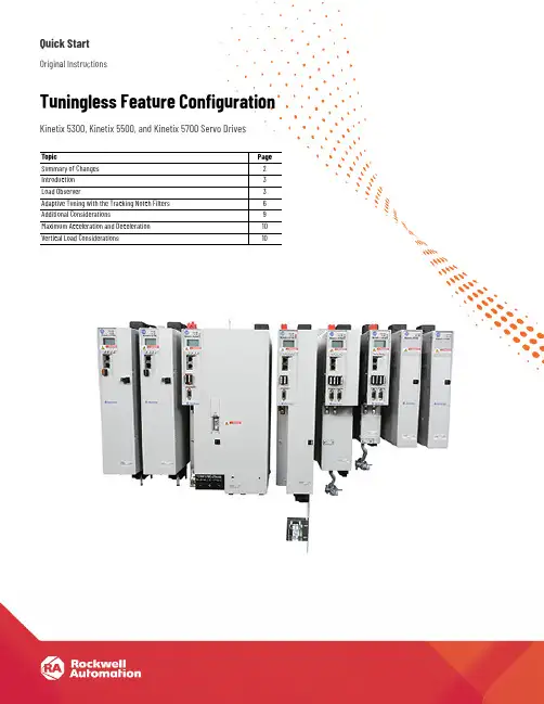
Quick StartOriginal InstructionsTuningless Feature Configuration Kinetix 5300, Kinetix 5500, and Kinetix 5700 Servo DrivesTopic Page Summary of Changes2 Introduction3 Load Observer3 Adaptive Tuning with the Tracking Notch Filters6 Additional Considerations9 Maximum Acceleration and Deceleration10 Vertical Load Considerations10Tuningless Feature Configuration Quick StartSummary of ChangesThis publication contains the following new or updated information. This list includes substantive updates only and is not intended to reflect all changes.Topic PageAdded references to Kinetix® 5300 servo drives throughoutUpdated screen captures to reflect latest version of the Studio 5000 Logix Designer® application throughout2Rockwell Automation Publication MOTION-QS001D-EN-P - November 2020Rockwell Automation Publication MOTION-QS001D-EN-P - November 20203Tuningless Feature Configuration Quick StartIntroductionClosed-loop servo systems require settings for the control loop gains and filter values to make sure that the load accurately follows the desired input-command signal. The process of adjusting and refining the gain and filter configuration is called tuning.Appropriate tuning settings depend heavily upon the system characteristics. Each machine behaves differently due to variables such as compliance, backlash, changing inertias, manufacturing tolerances, and machine degradation, so the tuning configuration can vary greatly from one machine to the next.With the tuning features of the Kinetix® 5300, Kinetix 5500, and Kinetix 5700 servo drives, tuningless operation can now be achieved without compromising on performance. By using both the load observer and the tracking notch filters in the servo drives, most applications no longer require tuning procedures and tests during the commissioning process to achieve an effective level of machine performance.Load ObserverThe load observer feature operates in real time while the machine is running. During machine operation, the load observer estimates the mechanical load inertia on the motor and compensates for it. The result is that the drive controls the motor as if it is unloaded, which provides a relatively high level of drive performance. In addition, the drive automatically compensates for mechanical variations in the system such as changing loads, compliance, and machine wear over time.ConfigurationThe following steps describe how to configure an axis with the recommended load observer settings for most applications. With the Logix Designer application version 33 and later, the load observer feature is enabled by default for the following drives, so these configuration steps are not required for tuningless operation:•Kinetix 5300 drives •Kinetix 5700 ERS3 Series B drives, with firmware revision 13 and later •Kinetix 5700 ERS4 drives, with firmware revision 13 and later1.In the Controller Organizer, right-click an axis and choose Properties. IMPORTANT Use the load observer with the tracking notch filters to achieve effective tuningless operation. IMPORTANTTo ensure stable operation, it is recommended that you do not perform the autotune test when applying the load observer feature.Tuningless Feature Configuration Quick Start2.Select the Autotune category.3.From the Application Type pull-down menu, choose Custom.4Rockwell Automation Publication MOTION-QS001D-EN-P - November 2020Rockwell Automation Publication MOTION-QS001D-EN-P - November 20205Tuningless Feature Configuration Quick Start 4.Clear the Torque Low Pass Filter checkbox.5.Select the Load category and verify that the Load Ratio is zero; otherwise, set it to zero.6.Under the Load category, select Observer.6Rockwell Automation Publication MOTION-QS001D-EN-P - November 2020Tuningless Feature Configuration Quick Start7.From the Configuration pull-down menu, choose ‘Load Observer with Velocity Estimate’ if the axis is configured for Position Loop control or ‘Load Observer Only’ if the axis is configured for Velocity Loop control. Load Observer is not available for Torque Loop control.8.Click Apply.Adaptive Tuning with the Tracking Notch FiltersThe tracking notch filters operate in real time while the machine runs. During machine operation, the drive measures the mechanical resonances in the system and dynamically sets the frequencies of the various notch filters to attenuate the effect of the resonances. ConfigurationThe following steps describe how to configure an axis with the recommended adaptive tuning settings for most applications. With the Logix Designer application version 33 and later, the tracking notch filters are enabled by default for the following drives, so these configuration steps are not required for tuningless operation•Kinetix 5300 drives •Kinetix 5700 ERS3 Series B drives, with firmware revision 13 and later •Kinetix 5700 ERS4 drives, with firmware revision 13 and laterIt is recommended that Position Loop control is used for both positioning and velocity applications. In select cases, application requirements may dictate Velocity Loop control.IMPORTANTUse the load observer with the tracking notch filters to achieve effective tuningless operation.Rockwell Automation Publication MOTION-QS001D-EN-P - November 20207Tuningless Feature Configuration Quick Start1.In the Controller Organizer, right-click an axis and then choose Properties.2.Under the Load category, select Compliance.3.From the Adaptive Tuning Configuration pull-down menu, choose Tracking Notch.With the Logix Designer application version 33 and later, the Compliance category parameters for the following drives will differ since they have four notch filters:•Kinetix 5300 drives•Kinetix 5700 ERS3 Series B drives, with firmware revision 13 and later•Kinetix 5700 ERS4 drives, with firmware revision 13 and laterTuningless Feature Configuration Quick Start4.Select the Cyclic Parameters Category.5.Scroll down and check TorqueNotchFilterFrequencyEstimate and TorqueNotchFilterMagnitudeEstimate.6.Click Apply.Selecting these parameters is optional. They are available to assist withcommissioning and provide diagnostic information.8Rockwell Automation Publication MOTION-QS001D-EN-P - November 2020Rockwell Automation Publication MOTION-QS001D-EN-P - November 20209Tuningless Feature Configuration Quick StartAdditional ConsiderationsFor more detailed technical information on the operation of the load observer or adaptive tuning features, see Chapter 1 of Motion System Tuning Application Techniques, publication MOTION-AT005.Notch Filter InitializationWith the Logix Designer application version 33 and later, the drive will persist adaptive tuning values through a drive power cycle for the following drives:•Kinetix 5300 drives •Kinetix 5700 ERS3 Series B drives, with firmware revision 13 and later •Kinetix 5700 ERS4 drives, with firmware revision 13 and laterFor details on how to retain the notch filter settings when power is removed and reapplied to the system, see Knowledgebase Technote Retaining Notch Filter Frequency through System Power Cycle .Increased PerformanceManual tuning may be used if higher performance is required after applying the default load observer gain values. It is recommended that you incrementally increase the bandwidth values while maintaining the following relationships:For Position Loop Control•Load Observer Bandwidth = 4 x Velocity Bandwidth = 16 x Position BandwidthFor Velocity Loop Control•Load Observer Bandwidth = Velocity BandwidthThe bandwidth values can be increased until the desired system performance is achieved.To reduce following error, it is recommended that Integrator Bandwidth be applied according to the following relationship:For Position Loop Control•Position Integrator Bandwidth = Position Bandwidth/100For Velocity Loop Control•Velocity Integrator Bandwidth = Velocity Bandwidth/10The integrator bandwidth value can be adjusted until the desired system performance is achieved. It is not recommended to use the position and velocity integrators simultaneously.For more detailed technical information on manual tuning, see chapter 4 of Motion System Tuning Application Techniques, publication MOTION-AT005.It is recommended that Position Loop control is used for both positioning and velocity applications. In select cases, application requirements may dictate Velocity Loop control.10Rockwell Automation Publication MOTION-QS001D-EN-P - November 2020Tuningless Feature Configuration Quick StartMaximum Acceleration and DecelerationWhen using the load observer feature, it is recommended that the load ratio is set to zero. For applications that use ‘percent of maximum’ as acceleration units for motion instructions, the Maximum Acceleration and Maximum Deceleration values for the application should bedecreased (as appropriate for the load) to stay within drive and motor limits during operation. The Maximum Acceleration and Deceleration attribute values can be found in the Planner category of the Axis Properties dialog box.Vertical Load ConsiderationsThe gain stabilization feature is not recommended for vertical loads, as detuning of the control loop gains produced by this feature may cause load drops. For more detailed information on techniques for managing vertical loads, see the Vertical Load and Holding Brake Management Application Technique, publication MOTION-AT003.Rockwell Automation Publication MOTION-QS001D-EN-P - November 202011Tuningless Feature Configuration Quick StartAdditional ResourcesThese documents contain additional information concerning related products from Rockwell Automation.You can view or download publications at rok.auto/literature .Resource DescriptionIndustrial Automation Wiring and Grounding Guidelines, publication 1770-4.1Provides general guidelines for installing a Rockwell Automation® industrial system.Product Certifications website, /global/certification/overview.pageProvides declarations of conformity, certificates, and other certification details.Servo Drive Installation Best Practices, publication MOTION-AT004Provides a quick reference of installation best practices for Rockwell Automation single-axis and multi-axis servo drive systems.Motion System Tuning Application Techniques, publication MOTION-AT005Provides information and tips for motion system tuning. Kinetix 5300 User Manual, publication MOTION-UM005Provides information on installing, configuring, starting, and troubleshooting your Kinetix 5300 servo drive system.Kinetix 5500 Servo Drives User Manual, publication 2198-UM001Provides information on installing, configuring, starting, and troubleshooting your Kinetix 5500 servo drive system.Kinetix 5700 Servo Drives User Manual, publication 2198-UM002Provides information on installing, configuring, starting, and troubleshooting your Kinetix 5700 servo drive system.Integrated Motion on the EtherNet/IP Network: Configuration and Startup User Manual, publication MOTION-UM003Information on how to configure and troubleshoot your ControlLogix® and CompactLogix™ EtherNet/IP™ network modules.Industrial Automation Wiring and Grounding Guidelines, publication 1770-4.1Provides general guidelines for installing a Rockwell Automation® industrial system.Product Certifications website, /global/certification/overview.pageProvides declarations of conformity, certificates, and other certification details.Servo Drive Installation Best Practices, publication MOTION-AT004Provides a quick reference of installation best practices for Rockwell Automation single-axis and multi-axis servo drive systems.Motion System Tuning Application Techniques, publication MOTION-AT005Provides information and tips for motion system tuning.Kinetix 5300 User Manual, publication MOTION-UM005Provides information on installing, configuring, starting, and troubleshooting your Kinetix 5300 servo drive system.Publication MOTION-QS001D-EN-P - November 2020Supersedes Publication MOTION-QS001C-EN-P - November 2018Copyright © 2020 Rockwell Automation, Inc. All rights reserved. Printed in the U.S.A.Rockwell Automation SupportUse these resources to access support information.Documentation FeedbackYour comments help us serve your documentation needs better. If you have any suggestions on how to improve our content, complete the form at rok.auto/docfeedback .Technical Support CenterFind help with how-to videos, FAQs, chat, user forums, and product notification updates.rok.auto/support KnowledgebaseAccess Knowledgebase articles.rok.auto/knowledgebase Local Technical Support Phone NumbersLocate the telephone number for your country.rok.auto/phonesupport Literature LibraryFind installation instructions, manuals, brochures, and technical data publications.rok.auto/literature Product Compatibility and Download Center (PCDC)Download firmware, associated files (such as AOP, EDS, and DTM), and access product release notes.rok.auto/pcdc Rockwell Automation maintains current product environmental compliance information on its website at rok.auto/pec .Allen-Bradley, ControlLogix, CompactLogix, expanding human possibility, Kinetix, Rockwell Automation, and Studio 5000 Logix Designer are trademarks of Rockwell Automation, Inc.EtherNet/IP is a trademark of ODVA, Inc.Trademarks not belonging to Rockwell Automation are property of their respective companies.Rockwell Otomasyon Ticaret A.Ş. Kar Plaza İş Merkezi E Blok Kat:6 34752, İçerenköy, İstanbul, Tel: +90 (216) 5698400 EEE Yönetmeliğine Uygundur。
Instrucciones de instalaciónJuegos de conectores de perfil bajo para señales de E/S, seguridad y retroalimentación auxiliarNúmero de catálogo 2090-K6CK-D44MAcerca de los juegos de conectores de perfil bajoEste juego de conectores de 44 pines ofrece puntos de terminación para E/S, conexiones de retroalimentación auxiliar y de seguridad para el conector IOD de las unidades Kinetix® 6200 y Kinetix 6500.El juego también incluye un puente habilitador de movimiento que se puede instalar cuando no se desea activar la funcionalidad de desconexión de par segura de los módulos de control 2094-xx02x-M0x-S0. El puente no es apto para los módulos de control 2094-xx02x-M0x-S1. Estos documentos contienen información adicional sobre el cableado de E/S, la seguridad y las conexiones de retroalimentación auxiliar para las unidades de servovariadores Kinetix 6200 y Kinetix 6500.2 Juego de conectores de perfil bajo para señales de E/S, seguridad y retroalimentación auxiliarRockwell Automation Publicación 2090-IN021D-ES-P - Enero 2015Cómo instalar el juegos de conectores de perfil bajoATENCIÓN: Este juego de conectores contiene piezas delicadas a descargas electrostáticas (ESD),que pueden sufrir daños si no se cumplen los procedimientos de control de ESD. Si no conoce los procedimientos de control de descargas electrostáticas (ESD), consulte la publicación n.º8000-4.5.2, Guarding Against Electrostatic Damage, o bien, cualquier otro manual de protección contra ESD que corresponda.1.Coloque el blindaje del cable expuesto en el canal.2.Conecte los cables a los terminales.3.Coloque la abrazadera de blindaje sobre el blindaje expuesto.4.Apriete los tornillos con un par de 0.4 N•m (3.5lb•pulg.).abrazadera para que los cables pequeños queden bien sujetos.Utilice abrazaderas de blindaje (3) para maximizar el contacto con el blindaje del cable en conexiones equipotenciales de alta frecuencia.Utilice sujetacables (4) para reducir la fatiga mecánica.Juego de conectores de perfil bajo para señales de E/S, seguridad y retroalimentación auxiliar 3Rockwell Automation Publicación 2090-IN021D-ES-P - Enero 2015Datos de los conectores(1)Los indicadores que se encuentran entre paréntesis hacen referencia al relé de seguridad Guardmaster® MSR57P y a los terminales de opción de seguridad serie 750 de PowerFlex®.(2)Utilice este suministro para alimentar la entrada de seguridad de 24 V (SPWR/SCOM). No conecte esta entrada de 24 V a ningún dispositivo de seguridad externo. Estos pines no son aptos para los módulos de control 2094-xx 02x -M0x S1.Instalación de puente habilitador de movimiento (aplica a los módulos de control 2094-xx 02x -M0x -S0).La numeración de pines del juego corresponde al conector IOD. Se asignan varios terminales a los pines 27, 28, 39 y 40 para que puedan adaptarse conexiones adicionales.Publicación 2090-IN021D-ES-P - Enero 2015© 2015 Rockwell Automation, Inc. Todos los derechos reservados. Impreso en EE.UU.Allen-Bradley, CompactLogix, Kinetix, MicroLogix, Rockwell Software y Rockwell Automation son marcas comerciales de Rockwell Automation, Inc.Las marcas comerciales que no pertenecen a Rockwell Automation son propiedad de sus respectivas empresas.Rockwell Automation mantiene información ambiental actualizada sobre los productos en su sitio web en/rockwellautomation/about-us/sustainability-ethics/product-environmental-compliance.page .Datos de los conectores (continuación)(1)Los indicadores que se encuentran entre paréntesis hacen referencia al relé de seguridad Guardmaster MSR57P y a los terminales de opción de seguridad serie 750 de PowerFlex.(2)Utilice estas señales como fuente de 24 VCC para operar las entradas digitales (máximo de 50 mA por entrada).Instalación de puente habilitador de movimiento (aplica a los módulos de control 2094-xx 02x -M0x -S0).La numeración de pines del juego corresponde al conector IOD. Se asignan varios terminales a los pines 27, 28, 39 y 40 para que puedan adaptarse conexiones adicionales.。

Kinetix 5500 伺服驅動器型號 2198-H003-ERS、2198-H008-ERS、2198-H015-ERS、2198-H025-ERS、2198-H040-ERS、2198-H070-ERS、2198-H003-ERS2、2198-H008-ERS2、2198-H015-ERS2、2198-H025-ERS2、2198-H040-ERS2、2198-H070-ERS2、2198-CAPMOD-1300本手冊連結至 Kinetix 5500 伺服驅動器故障碼參考資料,出版物2198-RD005,以供故障碼查詢。
立即下載試算表以離線存取。
2Rockwell Automation 出版品 2198-UM001L-ZC-P - 2022 年 2 月Kinetix 5500 伺服驅動器使用手冊使用者重要資訊進⾏本產品的安裝、設定、操作或維護前,請閱讀本文件及其他資源一節內有關本設備安裝、設定和操作的文件。
使用者除了必須瞭解所有相關法規、法律條文與標準外,還需熟知安裝與配線說明。
舉凡安裝、調整、運作、使用、組裝、拆卸及維護等作業,均需由受訓合格的⼈員依照相關法規進⾏。
若以製造商未提及之方式使用本設備,將可能損害到製造商為本設備所提供的保護措施。
不論任何情況,Rockwell Automation Inc. 對於使用或應用此裝置而產生的間接或連帶損壞,均不負擔任何法律或賠償責任。
本手冊中的範例和圖表皆僅供說明之用。
由於個別安裝會有許多不同的變數及條件,Rockwell Automation,Inc. 無法對依照範例及圖⽰指⽰進⾏的實際使用狀況負責或提供賠償。
關於本手冊中所述之資訊、電路、設備或軟體部分,Rockwell Automation Inc. 概不承擔任何專利責任。
在取得 Rockwell Automation Inc. 書面同意之前,禁止重製本手冊部分或全部內容。
在整本手冊中,我們會在必要時使用註記,讓您瞭解安全注意事項。
安装说明原版说明书译文轴密封套件产品目录号:VPL-SSN 、VPL-SS 、VPC-SSN 、VPF-SSN 、VPH-SST 、MPL-SSN 、MPF-SST 、MPS-SST 、TL-SSN变更摘要本出版物中包含新增和更新信息,如下表所述。
主题页码变更摘要1关于轴密封2所需工具2拆除轴密封3更换轴密封4轴密封套产品目录号6其他资源8主题页码轴密封的拆卸和更换步骤有更新。
3, 4轴密封安装间隙图表中增加了 Kinetix® VP 卫生型伺服电机。
5轴密封套件目录号表中增加了 Kinetix VP 卫生型伺服电机。
7轴密封套件关于轴密封当电机轴和端盖暴露在大量污染物,例如油、流体或微尘中时,建议安装轴密封。
在此类环境下使用轴密封可以延长电机使用寿命。
对于防护等级达到 IP66 或更高的应用项目,要求使用轴密封和带环境密封连接器的 Bulletin 2090 电缆。
参见 Kinetix Motion Accessories Specifications T echnical Data (Kinetix 运动附件技术规范,出版号:KNX-TD004),找到适用于您电机的带环境密封连接器的 Bulletin 2090电缆。
重要事项如果电机轴和端盖区域没有油、流体或微尘,并且使用较低的防护等级便能满足要求,则无需在这类应用中安装额外的轴密封。
轴密封较易磨损,需定期检查和替换。
根据使用情况,建议每 3 个月替换一次,最长不超过 12 个月。
如果要为电机喷漆,不得将油漆喷到轴密封区域或者轴上,否则会缩短轴密封的使用寿命。
所需工具使用以下工具安装轴密封:•尺寸适当的螺丝或螺栓,用于抓握并拆除损坏的轴密封•橡胶槌/木槌或金属锤和木制品•套筒、管道或管子 (各种尺寸)•砂布,用于去除电机轴上的任何划痕或毛刺2罗克韦尔自动化出版物 2090-IN012E-ZH-P - 2019年2 月罗克韦尔自动化出版物 2090-IN012E-ZH-P - 2019年2 月3轴密封套件拆除轴密封将尺寸适当的螺丝或螺栓部分插入轴密封面,即可安全拆除轴密封。
.Logix控制器对比表特性1756ControlLogix 1756 GuardLogix1768CompactLogix1769-L3xCompactLogix1769-L23xCompactLogix1789SoftLogix5800PowerFlex 700SPhase 2,带有DriveLogix控制器任务数:• 连续• 周期• 事件• 32个任务• 100个程序/任务• 事件任务:所有事件触发• 32个任务• 100个程序/任务• 事件任务:所有事件触发• 16个任务• 事件任务:消费者标签,事件(EVENT)指令,轴和运动事件触发• 1769-L35x:8个任务• 1769-L32x:6个任务• 1769-L31:4个任务• 事件任务:消费者标签和事件(EVENT)指令触发• 3个任务• 4个程序总数• 事件任务:消费者标签和事件(EVENT)指令触发• 32个任务• 100个程序/任务• 事件任务:所有事件触发,包括出站事件和Windows事件• 8个任务• 事件任务:轴和运动事件触发用户内存1756-L61:2 MB1756-L62:4 MB1756-L63:8 MB1756-L64:16 MB1756-L65:32 MB 1756-L61S:2 MB标准1 MB安全1756-L62S:4 MB标准1 MB安全1768-L43:2 MB1768-L45:3 MB1769-L31:512 KB1769-L32x:750 KB1769-L35x:1.5 MB512 KB 1789-L10:2 MB;1个控制器;无运动1789-L30:64 MB;3个控制器1789-L60:64 MB;6个控制器1.5 MB非易失性用户内存CompactFlash CompactFlash CompactFlash CompactFlash 无无CompactFlash内置通讯端口1个端口RS-232串口1个端口RS-232串口1个端口RS-232串口• 1769-L31:2个RS-232端口• 1769-L32C、1769-L35CR:1个ControlNet端口和1个RS-232串口• 1769-L32E、1769-L35E:1个EtherNet/IP端口和1个RS-232串口• 1769-L23E-QB1B:1个EtherNet/IP端口和1个RS-232串口•1769-L23E-QBFC1B:1个EtherNet/IP端口和1个RS-232串口• 1769-L23-QBFC1B:2个RS-232串口取决于个人计算机的配置1个端口RS-232串口通讯选项• EtherNet/IP• ControlNet• DeviceNet• Data Highway Plus• 远程I/O• SynchLink • EtherNet/IP (标准和安全)• ControlNet (标准和安全)• DeviceNet(标准和安全)• Data Highway Plus• 远程I/O• SynchLink• EtherNet/IP• ControlNet• DeviceNet• EtherNet/IP• ControlNet• DeviceNet• EtherNet/IP• DeviceNet• EtherNet/IP• ControlNet• DeviceNet• EtherNet/IP• ControlNet• DeviceNet串口通讯• ASCII• DF1全双工/半双工• DF1无线调制解调器• DH-485• 使用逻辑的Modbus • ASCII• DF1全双工/半双工• DF1无线调制解调器• DH-485• 使用逻辑的Modbus• ASCII• DF1全双工/半双工• DF1无线调制解调器• DH-485• 使用逻辑的Modbus• ASCII• DF1全双工/半双工• DF1无线调制解调器• DH-485• 使用逻辑的Modbus• ASCII• DF1全双工/半双工• DF1无线调制解调器• DH-485• 使用逻辑的Modbus• ASCII• DF1全双工/半双工• DH-485• 使用逻辑的Modbus• ASCII• DF1全双工/半双工• DF1无线调制解调器• DH-485• 使用逻辑的Modbus控制器连接数250 250 250 100 100 250 100网络连接数每个网络模块:• 100 ControlNet(CN2/A)• 40 ControlNet (CNB)• 256 EtherNet/IP;128 TCP (EN2x)• 128 EtherNet/IP;64 TCP (ENBT) 每个网络模块:• 100 ControlNet(CN2/A)• 40 ControlNet (CNB)• 256 EtherNet/IP;128 TCP (EN2x)• 128 EtherNet/IP;64 TCP (ENBT)每个网络模块:• 48 ControlNet• 64 EtherNet/IP;32 TCP每个控制器:• 32 ControlNet• 32 EtherNet/IP;32 TCP每个控制器:• 32 EtherNet/IP;8TCP每个网络模块:• 48 ControlNet• 128 EtherNet/IP;64 TCP每个网络模块:• 32 ControlNet• 32 EtherNet/IP;32 TCP控制器冗余完全支持无通过DeviceNet热备通过DeviceNet热备通过DeviceNet热备不适用不适用简单运动控制• 步进• DeviceNet的伺服• 模拟或网络交流变频器• 步进• DeviceNet的伺服• 模拟或网络交流变频器• 步进• DeviceNet的伺服• 模拟或网络交流变频器• 步进• DeviceNet的伺服• 模拟或网络交流变频器• 步进• DeviceNet的伺服• 模拟或网络交流变频器• 步进• DeviceNet的伺服• 模拟或网络交流变频器• 步进• DeviceNet的伺服• 模拟或网络交流变频器集成运动控制SERCOS接口模拟选项:• 编码器输入:• LDT输入• SSI输入SERCOS接口模拟选项:• 编码器输入:• LDT输入• SSI输入SERCOS接口不适用不适用SERCOS接口模拟量编码器输入• 1个完全伺服• 1个反馈轴编程语言• 梯形图• 结构文本• 功能块• SFC • 梯形图• 结构文本• 功能块• SFC• 梯形图• 结构文本• 功能块• SFC• 梯形图• 结构文本• 功能块• SFC• 梯形图• 结构文本• 功能块• DFC• 梯形图• 结构文本• 功能块• SFC• 外部例程 (用C/C++开发)• 梯形图• 结构文本• 功能块• SFC选择ControlLogix系统/输出(RTB)或配线(RTB) - 仅适用于模拟量接口模块(使用Motion)闪存卡3选择ControlLogix系统ControlLogix系统概述ControlLogix外形尺寸小,不仅可提供离散、传动、运动、过程和安全控制,同时具有先进的通讯能力和最新的I/O技术。
EL PAQUETE COMPLETOLos servovariadores Kinetix 5300 y Kinetix 5100 han sido diseñados para funcionar con el servomotor Kinetix TLP , lo cual ofrece soluciones completas de control de movimiento idóneas para máquinas pequeñas y medianas. Esta combinación de variador-motor está diseñada con todas las características esenciales para ayudar a los fabricantes de máquinas a ofrecer soluciones innovadoras y competitivas.Servovariadores Kinetix® 5300 y Kinetix 5100, y servomotor Kinetix TLP de Allen-Bradley®Soluciones versátiles de control de movimiento para máquinas pequeñas y medianasServovariador Kinetix 5100Debido a su diseño versátil, el Kinetix 5100 brinda una amplia gama de opciones de potencia para satisfacer las necesidades únicas de cada aplicación individual. Con una mayor variedad de opciones de potencia –hasta 15 kW– frente a alternativas comparables, los variadores Kinetix 5100 se pueden utilizar en el modo independiente o con controladores Micro800™ o Logix.Servomotor Kinetix TLPEste motor, probado y validado para brindar un rendimiento óptimo con los servovariadores Kinetix 5100 y Kinetix 5300, está disponible en ocho tamaños de estructura y en rangos de potencia de 50 W a 15 kW. Aproveche la amplia gama de cables y accesorios de motor para personalizar su sistema.Servovariador Kinetix 5300La integración transparente con el control Logix de Rockwell Automation® ofrece flexibilidad en el diseño de máquinas pequeñas y medianas para una variedad de aplicaciones de control de movimiento. Diseñado con todas las características esenciales incorporadas –una amplia gama de potencia, dos puertos Ethernet y desconexión de par segura cableada– el Kinetix 5300 es una excelente elección, idónea para laconstrucción o modernización de máquinas con un pequeño número de ejes.Obtenga más información en líneaSimplemente seguridad – La desconexión de par segura cableada viene incorporada en la versión estándar, lo que proporciona características de seguridad sin piezas ni mano de obra adicionales.Conéctese – El anillo a nivel de dispositivos (DLR)EtherNet/IP elimina la necesidad de accesorios adicionales.E/S – Cuatro entradas digitales, dos de las cuales se pueden utilizar como funciones de entradas digitales rápidas. El cableado de retroalimentación auxiliar se incluye como parte del conector de E/S.Gama de potencia – Potencias nominales de 0.05…2 kW a 120…230 V, 3…7.5 kW a 230 V y 0.4…7.5 kW a 460 V. La potencia nominal se refiere a la potencia de salida del motor, lo cual simplifica y facilita los esfuerzos de dimensionamiento.Integración Logix – La integración con Logix como un único núcleo de control y Studio 5000 como un único ambiente de diseño facilitan el diseño, la implementación y el control de la máquina.Puesta en marcha sin ajustes – Las características como el seguimiento de filtros de muesca y los observadores de carga ayudan a simplificar la puesta en marcha y a mantener el funcionamiento adecuado de la máquina con ajustes automáticos.CARACTERÍSTICAS Y VENTAJASServovariador Kinetix 5300Servovariador Kinetix 5100CARACTERÍSTICAS Y VENTAJASSeguridad simple – La desconexión de par segura cableada vieneincorporada en la versión estándar en todas las unidades, lo queproporciona características de seguridad sin piezas ni mano de obraadicionales.E/S – Diez entradas digitales libremente asignables (dos de las cuales sepueden utilizar como funciones de entradas digitales rápidas) y cincosalidas digitales libremente asignables.Cambio rápido – El modo de control cambia (es decir, velocidad a par)sobre la marcha. Por eso, el sistema de control puede cambiar de modossin interrumpir la condición de funcionamiento.Funcionamiento suave – El funcionamiento de máquina optimizado conmenores necesidades de ajuste manual minimiza las vibraciones sin queesto afecte el tiempo de repuesta del sistema.Gama de potencia – Más amplia gama de potencia en comparación conotras soluciones (0.05…2 kW a 120…230 V, 3…15 kW a 230 V y 0.4…15 kWa 460 V) para armonizar la potencia con la aplicación.Más acción, menos distracción – El indexado y la función eCAMproporcionan más comandos de movimiento que otros productos sinnecesidad de tener sistemas de control separados.Independiente e interconectable – Elija su propio control con tresopciones: control independiente, conectividad a controladores Micro800o conectividad a controladores Logix. Configuración rápida y fácil. Losvariadores Kinetix 5100 se integran de manera transparente en lasaplicaciones Logix con AOI de diseño especial.Obtenga más información en líneaServomotor Kinetix TLP y accesoriosObtenga más información en líneaCARACTERÍSTICAS Y VENTAJASOpciones de tamaños – Disponible en ocho tamaños de estructura desde 46 mm hasta 235 mm y opciones de 200 V o 400 V.Resolución – Retroalimentación absoluta de alta resolución de 24 bits.Gama de potencia – Potencias nominales de 50 W a 15 kW – una gama más amplia que la de otros motores similares.Rendimiento comprobado, uso global – El servomotorKinetix TLP está reconocido por UL/CSA y ostenta la marca CE. Opción de freno – Opción de freno integral de 24 VCC que permite personalizar la máquina.La elección perfecta – Una amplia selección de longitudes de cable (hasta 50 metros) tanto en opciones flexibles como no flexibles, que permite satisfacer una variedad de requisitos de espacio y diseños de máquinas.Catálogo de motores Catálogo de variadores Velo-cidad nominal Velocidad máx.Par de paro continuo, Nm Par de paro pico, Nm Salida nominal, kW TLP-A046-0052198-C1004-ERS 300060000.160.4470.05TLP-A046-0102198-C1004-ERS 300060000.32 1.0340.10TLP-A070-0202198-C1004-ERS 300060000.64 2.160.20TLP-A070-0402198-C1004-ERS 30006000 1.27 4.2750.40TLP-A090-0752198-C1007-ERS 30006000 2.397.5050.75TLP-A100-1002198-C1015-ERS 30003000 3.188.74 1.00TLP-A115-1002198-C1015-ERS 30005000 3.188.455 1.00TLP-A115-2002198-C1020-ERS 30005000 6.2217.48 1.952198-C2030-ERS 30005000 6.3717.48 2.00TLP-A145-0502198-C1007-ERS 20003000 2.39 6.810.50TLP-A145-0902198-C1015-ERS 100020008.5920.520.90TLP-A145-1002198-C1015-ERS 20003000 4.7713.30 1.00TLP-A145-1502198-C1015-ERS 20003000 6.9219.66 1.452198-C1020-ERS 200030007.1619.66 1.50TLP-A145-2502198-C2030-ERS 300045007.9624.51 2.50TLP-A200-2002198-C1020-ERS 200030009.5021.85 1.982198-C2030-ERS 200030009.5521.85 2.00TLP-A200-3002198-C2030-ERS 1500250018.4947.03 2.902198-C2055-ERS 1500250019.1047.03 3.00TLP-A200-3502198-C2055-ERS 2000300016.7143.23 3.50TLP-A200-4502198-C2055-ERS 1500300028.6564.04 4.50TLP-A200-5502198-C2055-ERS 1500300034.2279.96 5.382198-C2075-ERS 1500300035.0179.96 5.50TLP-A200-7502198-C2075-ERS1500250045.72104.307.18Servovariador Kinetix 5300 y servomotor Kinetix TLPCatálogo de motores Catálogo de variadores Velocidad nominal Velo-cidad máx.Par de paro continuo, Nm Par de paro pico, Nm Salida nominal, kWTLP-B070-0402198-C4004-ERS 30006000 1.27 4.2500.40TLP-B090-0752198-C4007-ERS 30006000 2.32 6.9000.732198-C4015-ERS 30006000 2.398.050.75TLP-B115-1002198-C4015-ERS 30005000 3.189.340 1.00TLP-B115-2002198-C4020-ERS 30005000 6.3717.90 2.002198-C4030-ERS 30005000 6.3719.10 2.00TLP-B145-0502198-C4007-ERS 20003000 2.39 6.930.50TLP-B145-1002198-C4015-ERS 20003000 4.7713.03 1.00TLP-B145-1502198-C4015-ERS 200030007.1620.16 1.502198-C4020-ERS 200030007.1620.54 1.50TLP-B145-2002198-C4020-ERS 200030009.5524.40 2.00TLP-B145-2502198-C4030-ERS 300045007.9626.30 2.50TLP-B200-3002198-C4030-ERS 1500250019.1047.80 3.00TLP-B200-4502198-C4055-ERS 1500300028.7067.60 4.50TLP-B200-5502198-C4055-ERS 1500300033.4973.60 5.302198-C4075-ERS 1500300035.0083.80 5.50TLP-B200-7502198-C4075-ERS1500250045.40101.307.10Combinación del sistema de servovariador Kinetix 5100 y servomotor Kinetix TLPCatálogo de motores Catálogo de variadores Velocidad nominal Veloci-dad máx.Par de parocontinuo, NmPar de paro pico,Nm Salida nominal, kWTLP-A046-0052198-E1004-ERS 300060000.160.4470.05TLP-A046-0102198-E1004-ERS 300060000.32 1.0340.10TLP-A070-0202198-E1004-ERS 300060000.64 2.160.20TLP-A070-0402198-E1004-ERS 30006000 1.22 2.910.382198-E1007-ERS 30006000 1.27 4.2750.40TLP-A090-0752198-E1007-ERS 30006000 2.397.5050.75TLP-A100-1002198-E1007-ERS 30003000 3.188.74 1.002198-E1015-ERS 30003000 3.188.74 1.00TLP-A115-1002198-E1015-ERS 30005000 3.188.455 1.00TLP-A115-2002198-E1020-ERS 30005000 6.3717.48 2.00TLP-A145-0502198-E1007-ERS 20003000 2.39 6.810.50TLP-A145-0902198-E1015-ERS 100020008.320.520.872198-E1020-ERS 100020008.5920.520.90TLP-A145-1002198-E1015-ERS 20003000 4.7713.3 1.00TLP-A145-1502198-E1015-ERS 20003000 6.2215.92 1.302198-E1020-ERS 200030007.1619.66 1.50TLP-A200-2002198-E1020-ERS 200030009.5533.66 2.00TLP-A200-3002198-E2030-ERS 1500250016.8145.62 2.642198-E2055-ERS 1500250019.147.03 3.00TLP-A200-3502198-E2055-ERS 2000300016.7143.23 3.50TLP-A200-4502198-E2055-ERS 1500300028.6564.04 4.50TLP-A200-5502198-E2055-ERS 1500300035.0167.67 5.502198-E2075-ERS 1500300035.0179.96 5.50TLP-A200-7502198-E2075-ERS 1500250045.36104.37.122198-E2150-ERS 1500250047.74104.37.50TLP-A235-11K 2198-E2150-ERS 1500200070.0144.311.00TLP-A235-15K2198-E2150-ERS1500200095.4184.615.00Catálogo de motores Catálogo de variadores Velocidad nominal Velo-cidad máx.Par de paro continuo, Nm Par de paro pico, Nm Salida nominal, kW TLP-B070-0402198-E4004-ERS 30006000 1.27 4.250.40TLP-B090-0752198-E4007-ERS 30006000 2.39 5.930.752198-E4015-ERS 30006000 2.398.050.75TLP-B115-1002198-E4015-ERS 30005000 3.189.34 1.00TLP-B115-2002198-E4020-ERS 30005000 6.3715.62 2.002198-E4030-ERS 30005000 6.3719.10 2.00TLP-B145-0502198-E4007-ERS 20003000 2.39 6.930.50TLP-B145-1002198-E4015-ERS 20003000 4.7713.03 1.00TLP-B145-1502198-E4015-ERS 200030007.1616.92 1.502198-E4020-ERS 200030007.1620.54 1.50TLP-B145-2002198-E4020-ERS 200030009.5523.74 2.002198-E4030-ERS 200030009.5524.40 2.00TLP-B145-2502198-E4030-ERS 300045007.9620.51 2.502198-E4055-ERS 300045007.9626.30 2.50TLP-B200-3002198-E4030-ERS 1500250019.1036.57 3.002198-E4055-ERS 1500250019.1047.80 3.00TLP-B200-4502198-E4055-ERS 1500300028.7043.60 4.502198-E4150-ERS 1500300028.7067.60 4.50TLP-B200-5502198-E4055-ERS 1500300035.0047.35 5.502198-E4150-ERS 1500300035.0083.80 5.50TLP-B200-7502198-E4075-ERS 1500250047.7077.207.502198-E4150-ERS 1500250047.70101.307.50TLP-B235-11K 2198-E4150-ERS 1500200070.00158.5011.00TLP-B235-14K2198-E4150-ERS1500200089.10143.6014.00Publicación KNETIX-PP001B-ES-P – Noviembre 2020 | Sustituye a la publicación KNETIX-PP001A-ES-P – Octubre 2019Copyright © 2020 Rockwell Automation, Inc. Todos los derechos reservados. Impreso en EE. UU.Allen-Bradley, expanding human possibility, Kinetix, Micro800 y Rockwell Automation son marcas comerciales de Rockwell Automation, Inc.Las marcas comerciales que no pertenecen a Rockwell Automation son propiedad de sus respectivas empresas.Conéctese con nosotros.。
SPECIFICATIONSProduct SeriesComponent Type Motion Control Mounting, MotorBrakeFood GradeConnector, Motor EndKeyed ShaftFeedback TypeFeedback Resolution Feedback ProtocolSpeed, RatedSpeed, MaxMagnet Stack LengthFrame SizeVoltage ClassShaft SealSpecial / CustomOutput Torque, Continuous Output Torque, Peak Compatible Drive Series'Rated Power, ContinuousRotor InertiaOperating Temperature, Max Operating Temperature, Min MPL Low InertiaRotary Servo MotorFlange Mount, MetricNo Y / NNoSpeedTec DIN (Type M7)Yes Y / NAbsolute Single-turn typeSin/Cos, 128 cycles/rev resolutionHiperface protocol7000rpm7000rpm20 = 50.8mmFrame 15 / Frame 063 = 63mm size200V ACNo Y / NNo0.49Nm, continuous1.58NmKinetix 5500 (Bul. 2198)Kinetix 6200 / 6500 (Bul. 2094)Kinetix 6000 (Bul. 2094)Kinetix 300 (Bul. 2097)Kinetix 350 (Bul. 2097)Kinetix 2000 (Bul. 2093)Kinetix 7000 (Bul. 2099)Ultra 3000 (Bul. 2098)compatible0.27kW continuous1.3E-05kg m², rotor40°C max0°C min·Continuous stall torque of 0.26 to 163Nm (2.3 to 1440lb-in.)·Peak torque of 0.77 to 278Nm (6.8 to 2460lb-in.)·Integral 24V brake option·Absolute multi-turn and single-turn high resolution, incremental encoder and resolver feedback options·Low-profile, field-reversible motor connectors for minimal servo motor impact on machine design·DIN connector versions allow flexible orientation of connectors and use of a single cable family with all MP-Series motorsRepresentative Photo Only(actual product may vary based on configuration selections)MP SERIES MPL 240V SERVO MOTOR,0.49 N-M,7000 RPM1300 NHP NHP | .au | 0800 NHP NHP | MPLA1520UEJ72AA DatasheetNHP Electrical Engineering ProductsOperating Temperature, MinStorage Temperature, MaxStorage Temperature, MinRelative humidity, minRelative Humidity, MaxHumidity typeWeightIP RatingDetails, IP RatingShock Acceleration (Max.)Shock Duration (Max.)Vibration Acceleration (Max.)Vibration Frequency, Operational (Max.)0°C min70°C max-30°C min5%RH95%RHNon-condensing1.2kgIP50IP66IP50 minimum, without shaft seal; IP66 with optional shaft seal and use of environmentally sealed cable connectors20g6ms2.5g2000HzREFERENCESInstallation Guide:-User Manual:-Manufacturer Datasheet:-Manufacturer Catalogue & Product Selection:-Supplier Declaration of Conformity:-IECEx Certificate-1300 NHP NHP | .au | 0800 NHP NHP | MPLA1520UEJ72AA DatasheetNHP Electrical Engineering Products。
Packing Data Continuous Flex Brake, or Power with Brake CablesCatalog Numbers 2090-CPBM4DF-xx AF xx, 2090-UXTBMP-18S xxTopic PageAbout Continuous Flex Cables 3Installing Cables 4 Specifications, Schematics, and Connector Pinouts for Cables 62090-CPBM4DF-xxAFxx Flying Lead 72090-UXTBMP-18Sxx Flying Lead 8OverviewThis document provides general cable handling and installation information, and cable schematics with wire color and connector pinouts. This information is useful when connecting brake cables to Kinetix Motion Control products.2 Continuous Flex Brake, or Power with Brake Cables Packing DataImportant User InformationSolid state equipment has operational characteristics differing from those of electromechanical equipment. Safety Guidelines for the Application, Installation and Maintenance of Solid State Controls (Publication SGI-1.1 available from your local Rockwell Automation sales office or online at) describes some important differences between solid state equipment and hard-wired electromechanical devices. Because of this difference, and also because of the wide variety of uses for solid state equipment, all persons responsible for applying this equipment must satisfy themselves that each intended application of this equipment is acceptable.In no event will Rockwell Automation, Inc. be responsible or liable for indirect or consequential damages resulting from the use or application of this equipment.The examples and diagrams in this manual are included solely for illustrative purposes. Because of the many variables and requirements associated with any particular installation, Rockwell Automation, Inc. cannot assume responsibility or liability for actual use based on the examples and diagrams.No patent liability is assumed by Rockwell Automation, Inc. with respect to use of information, circuits, equipment, or software described in this manual.Reproduction of the contents of this manual, in whole or in part, without written permission of Rockwell Automation, Inc., is prohibited.Throughout this manual, when necessary, we use notes to make you aware of safety considerations.Publication 2090-PC005A-EN-P - August 2008Continuous Flex Brake, or Power with Brake Cables Packing Data 3Publication 2090-PC005A-EN-P - August 2008About Continuous Flex CablesFlex cables have an identifiable region, the flex zone, in which the cable can flex many times without breakage. This contrasts with non-flex cables that are limited to a one-time bend.The Kinetix Motion Control Selection Guide , publication GMC-SG001, also contains specifications, as well as information on cable compatibility with specific drives and motors.Refer to these drive manuals for specific examples on how to use the cables in this document to interface between your drive and motor.These publications are available from your local Rockwell Automation sales office or online at . ResourceDescription Kinetix 2000 Multi-axis Servo Drive User Manual, publication2093-UM001 Provides mounting, wiring, andapplication-based information for a Kinetix multi-axis or an Ultra single-axis servo drive systemand its components. Kinetix 6000 Multi-axis Servo Drive User Manual, publication 2094-UM001 Kinetix 7000 High Power Servo Drive User Manual, publication 2099-UM001 Ultra1500 Digital Servo Amplifiers User Manual, publication2092-UM001Ultra3000 Digital Servo Drive Installation Manual, publication2098-IN003 or Integration Manual, publication 2098-IN005Ultra5000 Intelligent Positioning Drives Installation Manual,publication 2098-IN0014 Continuous Flex Brake, or Power with Brake Cables Packing DataInstalling CablesCables are stored and shipped in a coil, and will retain this shape unless you allow the cable to straighten itself. To straighten a cable, hang a short cable from its mid-point or lay a long cable on the floor in a straight line. Any coiling that persists in the cable should relax within the next twenty-four hours. Doing this results in a cable that is easier to install.Arcing or unexpected motion can occur if the power, brake, or feedbackcables are connected or disconnected while power is applied to the drive.Always remove power to the servo drive before connecting or disconnectingcables at the drive or at the motor.Failure to observe these safety procedures could result in personal injury ordamage to the motor and equipment.To avoid the hazard of electrical shock, ensure shielded power cables aregrounded at a minimum of one point. To prevent the build-up of electricalenergy, factory supplied power cables use one of these groundingtechniques:· The overall shield is bonded to the connector housing.· A section of the overall shield is exposed for connection to ground.· The overall shield is connected to a ground wire.If the exposed cable braid or a ground wire is present, connect it to the powercable clamp, housing, or another suitable chassis ground on the drive.Failure to observe these safety procedures could result in personal injury orequipment damage.Publication 2090-PC005A-EN-P - August 2008Continuous Flex Brake, or Power with Brake Cables Packing Data 5Publication 2090-PC005A-EN-P - August 2008You must provide the recommended installation areas, and the correct offset from features, before beginning any cable bend. Features include connectors, transitions from exposed wires to insulated areas (for example, flying leads), or exposed cable ground shields. The offset from these areas should be greater than or equal to (>1x) the cable diameter. Cable Flex Zone and Installation Areas with Bend RestrictionsDo not tightly gather or coil the excess length of a power cable. Heat isgenerated within a cable whenever power is applied. Always position apower cable so it may freely dissipate any heat.A power cable should not be coiled, except for temporary use whenbuilding or testing a machine. If you temporarily coil a power cable, youmust also derate the cable to meet local code or follow a authoritativedirective, such as Engineering Section 310.15(C) of the NEC Handbook.Failure to observe these safety procedures could result in personal injury or equipment damage.The examples in this publication show all the available connections, some ofwhich may not be appropriate for your specific installation. Refer to yourdrive installation or user manual for recommended wire trim lengths, andwiring examples appropriate to your drive and motor application.Do not connect unused wires. Unused wires may be trimmed and finished asnecessary to prevent accidental contact with other wires or wire shields, orwith a ground connection.Failure to observe these safety procedures could result in personal injury ordamage to the motor and equipment.Flex Area CPBM4DF-xxAFxx shown Installation AreaInstallation Area6 Continuous Flex Brake, or Power with Brake Cables Packing DataPublication 2090-PC005A-EN-P - August 2008Cables have a specified bend radius, and should not be bent with a radius that is tighter than the specified bend radius. General guidelines for the bend radius of a cable are listed below, however individual cables may have other restrictions:·Non-flex cables have a static or one-time bend radius of ten times (10x) the cable diameter.·Flex cables have an operational bend radius of twelve times (12x) the cable diameter.You may identify each connection on a cable by attaching a label around the outer insulation of each wire adjacent to the drive connection.Specifications, Schematics, and Connector Pinouts for Cables These specifications provide information that is useful when installing a cable. Additional specifications for each cable are available in the Kinetix Motion Control Selection Guide , publication GMC-SG001.Specifications for Continuous Flex Brake, or Power with Brake Cables Attribute ValueCatalog Numbers (1)(1)Bend radius formulas for static (10x) and operational (12x) bend radius should be applied to cables using other wire gauges.2090-CPBM4DF-xxAFxx Flying Lead, 2090-UXTBMP-18Sxx Flying Lead Wire Size16 AWG 14 AWG 10 AWG Diameter12.5 mm 13.7 mm 17.8 mm Bend Radius (2)(2)Apply the multiplier for operational (12 x dia.) and static (10 x dia.) bend radius to cables with a different diameter. Refer to the diagram to locate the areas for flex (operational), and static (installation) bend areas.•Flex Area150 mm (6.0 in.) 165 mm (6.5 in.) 214 mm (8.5 in.) •Installation Areas (3)(3)The installation areas are approximately 300 mm (12 in.) in length at both ends of the cable. Secure this area with a rigid mount that prevents the cable from flexing where it connects to other components. 125 mm (5.0 in.) 137 mm (5.5 in.) 178 mm (7.0 in.)Continuous Flex Brake, or Power with Brake Cables Packing Data 7Publication 2090-PC005A-EN-P - August 2008The schematics include wire colors, connector pinouts, and otherinformation that is useful when connecting the cable to a servo system. 2090-CPBM4DF-xx AF xx Flying LeadThis cable is available in several wire gauges and lengths. Refer to the Kinetix Motion Control Selection Guide, publication GMC-SG001, for this information and additional specifications.1Wire gauge (10, 14 or 16 AWG) and connector keying varies based on motor and power requirements. Refer to Kinetix Motion Control Selection Guide, publication GMC-SG001, for additional information.required.ToDrive (Heatshrink insulateswire-to-wire connections.)Publication 2090-PC005A-EN-P - August 2008PN-26580Copyright © 2008 Rockwell Automation, Inc. All rights reserved. Printed in the U.S.A.Allen-Bradley, Kinetix, Rockwell Automation, Ultra1500, and Ultra 5000 are trademarks of Rockwell Automation, Inc.Trademarks not belonging to Rockwell Automation are property of their respective companies.2090-UXTBMP-18S xx Flying LeadThis cable is available in several wire gauges and lengths. Refer to the Kinetix Motion Control Selection Guide, publication GMC-SG001, for thisinformation and additional specifications.360°ToDrive。