Modeling a Service Function for Time-on-Task Allocation
- 格式:pdf
- 大小:116.98 KB
- 文档页数:4

A Service of Love爱的牺牲作者介绍欧·亨利(O.Henry)1862-1910,原名威廉·西德尼·波特(William Sydney Porter),美国著名小说家,与法国的莫泊桑、俄国的契诃夫并称为世界三大短篇小说巨匠。
他的短篇小说构思巧妙,手法独特,以幽默的语言和出人意料的结局而闻名于世,大多表现美国中下层人民的生活,被誉为“美国生活的百科全书”。
著名作品有:《最后一片藤叶》(The Last Leaf)、《警察与赞美诗》(The Cop and the Anthem)、《麦琪的礼物》(The Gift of the Magi)等。
作品介绍《爱的牺牲》讲述了一对怀有艺术梦想的夫妇,在爱与信仰的精神支撑下共同为生活奋斗的故事。
乔·拉雷毕有绘画天赋,而他的妻子迪莉娅·拉雷毕热爱音乐。
为了维持生计和实现彼此的梦想,他们放下高雅的艺术追求,一个去街头卖风景画,另一个去教富家小姐音乐课,而现实中的身不由己,却让两人演绎了一出阴差阳错的人间喜剧。
如同欧·亨利大多数以爱情为主题的作品相似,该故事也选取了社会中最普通的大众作为主角,从他们普通而琐碎日常生活中将“为爱牺牲”这个永恒而温馨的主题娓娓道来。
1enthusiasticadj. 热心的;热情的;热烈的;狂热的2coddle vt.悉心照料,娇惯3languid adj.疲倦的; 没精打采的,呆滞的; 萧条的; 慢吞吞4triumphantlydv.耀武扬威地,得意扬扬地5monotonousadj.枯燥无味的; (声音,话语)单调的,无抑扬顿挫的6widowern.鳏夫7obeliskn.方尖碑8overwhelminglyadv.压倒地,无法抵抗地9game adj.对…有兴趣的;10freight n.货运,货物; 运费; 船运货物; 货运列车11queer adj.古怪的; 可疑的; 不适的12distracted adj.思想不集中的; 心烦意乱的13plaintivelyadv.悲哀地,哀怨地14stubbornnessn.倔强,顽强; 牛性; 牛脾气; 犟劲15confess vt.& vi.承认; 聆听(某人的)忏悔(或告罪、告解)作品赏析:欧·亨利的短片小说大多从“小”处着眼。

GE China Technology Center通用电气中国研发中心通用电气公司(GE)是一家集科技、传媒、金融服务于一身的多元化公司,致力于为客户解决世界上最棘手的问题。
GE的产品和服务范围广泛,从飞机发动机、发电设备、水处理和安防技术,到医疗成像、商务和消费者金融、媒体,客户遍及全球100多个国家,拥有30多万员工。
杰夫·伊梅尔特先生是现任董事长及首席执行官。
GE是全球500强企业中始终保持领先的企业,GE是道.琼斯工业指数1896年设立以来,唯一一家至今仍在指数榜上的公司。
GE中国研究开发中心(CTC)是GE公司四个全球研发中心之一,是跨业务集团、跨研究领域的研发机构,为GE各业务集团提供基础科学研究、新产品开发、工程开发和采购服务。
中心坐落于上海张江高科技园区,占地面积47,000平方米,于2003年5月投入使用,是国内最大的独立外资研发机构之一,也是国内极少数具有基础科学研究能力的企业研发中心。
GE中国研发中心现有研发人员1200多人,60多个拥有世界一流设备的实验室,其研究力量主要集中在以下领域:·清洁能源,包括洁净煤、风电、太阳能发电等;·海水淡化与水处理;·材料科学,包括纳米材料、晶体、陶瓷,材料分析;·电力电子和实时控制;·安防技术;·先进制造技术;·影像技术;·化学技术,如导电高分子,电化学技术GE中国研发中心每年完成100多个研究项目,其中包括三分之一左右的基础科研项目。
截至2008年底,GE 中国研发中心共申请了320多项专利。
The GE China Technology Center, driving GE’s growth in China and globallyOne of four global research and development facilities at the hub of GE’s worldwide technology development efforts, the GE China Technology Center (CTC) is a diversified, multi-disciplinary organization conducting fundamental research, new product development, engineering service and sourcing service.Located at Zhangjiang High-Tech Park, the China Technology Center (CTC) has been operational since May 2003 with a total physical area of 47,000 square meters. CTC is one of the biggest foreign invested R&D centers and among the very few enterprise R&D centers which have fundamental research capabilities.With more than 1,200 researchers and engineers and 60+ labs, CTC teams are driven to bring technology breakthroughs and product innovations to life in the following key areas:• Energy, including Clean Coal, Wind Power, Solar Power, etc. • Water, including Seawater desalination and water treatment • Material, including nano-material, crystal, etc. • Electronic and electric, real time control • Security systems• Advanced manufacture • Imaging Technology • ChemicalGE China Technology Center accomplished more than 100 R&D projects every year, one third of which are fundamental research projects. Till the end of 2008, CTC has filed more than 320 patent applications.如何申请职位:选择1. · 请访问/careers/ · 根据职位编号申请职位; ·在线投递简历.选择2. 请将简历直接投递至 yuxiao.tang@ (请在邮件中注明申请得职位编码)更多信息请访问GE 网站 : or How to apply:Option 1: Please visit: /careers/Please search and apply the jobs by job code Please submit your CV on-lineOption 2: Please send your CV directly to yuxiao.tang@ (Please remark the job code in your mail)More information, please visit GE website: or All the Positions below will be Located in Shangha iPOSITION TITLE: Lead Engineer-Signal Processing (Algorithm)(Job Code: 1008431)Work Location: Shanghai Reqs: 1 Language: FluentEnglish3-5 yearsDegree: Master / PhD WorkingExperience:JOB DESCRIPTION:ESSENTIAL FUNCTION / RESPONSIBILITIES:conceptual design and algorithm validation, contribute to intelligence-embedded electronic system for SDE future development.QUALIFICATIONS / REQUIREMENTS:PhD degree with major in Signal Processing, Automation Control or related areas;· 5 years above signal processing experience in medical/military/industry applications;· Strong analytical capability in system modeling and verification through simulation;· Strong experience in algorithm implement and optimization for embedded systems based on micro-processors/MCU/DSP;· In-depth knowledge in advanced signal processing techniques, e.g. adaptive/statistical/array/image signal processing;· Excellent programming skills: Matlab, C/C++ and assembly languages;· Knowledge in embedded OS, signal processing system will add advantages;. Demonstrated leadership and problem solving skills; Excellent language skill on English reading, speaking and writing.POSITION TITLE: Lead Engineer-Embedded System (Hardware)(Job Code: 1008436)Work Location: Shanghai Reqs: 1 Language: FluentEnglish3-5 yearsDegree: Master / PhD WorkingExperience:JOB DESCRIPTION:ESSENTIAL FUNCTION / RESPONSIBILITIES:conceptual design, implement and validation of embedded systems based on micro-processors/ /MCU/DSP/FPGA. QUALIFICATIONS / REQUIREMENTS:. PhD degree with major in Embedded Systems, Automation Control, Signal Processing or related areas;· Must have 3 years above working experience in hardware design, at least 2 year hand-on experience in FPGA;· Solid knowledge in digital/analog electronics;· Strong experience in plan, design, implement, debug and optimizing embedded system based on micro-processors/MCU/DSP/FPGA;· Proficiency in FPGA development tool-chain and design flow;· Excellent programming skills: VHDL/Verilog, C/C++ and assembly languages;· Knowledge in embedded OS, signal processing system will add advantages;· Demonstrated leadership and problem solving skills; Excellent language skill on English reading, speaking and writing.POSITION TITLE: Lead Engineer(Job Code: 1104592)Work Location: Shanghai Reqs: 1 Language: FluentEnglish3-5 yearsDegree: Master / PhD WorkingExperience:JOB DESCRIPTION:ESSENTIAL FUNCTION / RESPONSIBILITIES:"· Formulates, implements and executes on new programs or integrates major programs to meet key technical objectives. Champion new ideas.· Interfaces with related technology areas/labs.· Be responsible for project execution and technical deliverables. Leverages broad technical experience to ensure success of projects.· Has an expanded network through participation in development activities.· Builds customer relationships and communicates with the customer on technology development activities. Influences customer technical direction.QUALIFICATIONS / REQUIREMENTS:"· PhD in chemical engineering/thermal engineering· Industrial R&D experience in Coal Conversion/IGCC/Polygeneration· Proven record of technical accomplishments in the related field.· Strong leadership traits; experience in leading technology team.· Strong interpersonal skills and excellent communication skills.· Ability to build and maintain strong customer relationships.· Excellent problem solving skills - ability to consider overall problem, identify opportunities and implement major changes.· Self-starter & self-motivator, independent thinker, proactive problem solver.· Motivated by quality, cost and speed.· High energy with passion for excellence (Demonstrated ability to set and achieve aggressive goals and targets; Embrace change and technology evolution as an opportunity).· Strong environmental, health and safety ethics.· Fluent oral and written communication in EnglishDesired Characteristics:"· > 6 years industrial R&D experiences in Coal Conversion/IGCC/Polygeneration.· Good technical reputation in the area of expertise.· Technology vision and big picture in the understanding of the industrial trends.POSITION TITLE: Principal Engineer– Organic Materials & Surface Chemistry(Job Code: 1061942)Work Location: Shanghai Reqs: 1 Language: FluentEnglish10 yearsDegree: PhD WorkingExperience:JOB DESCRIPTION:ESSENTIAL FUNCTION / RESPONSIBILITIES:- Strong strategic focus & influence to drive organization technologies- Formulates, implements and executes on new programs or integrates major programs to meet key technical objectives. Champion new ideas- Responsible for technical growth of the organization. Recognized for technical expertise and breath- Considered a technical resource for complex, multi-disciplinary issues, works across discipline boundaries to integrate experience to ensure success of projects- Ability to lead projects and initiatives with broad scope and high impact to the business- Be responsible for program execution and technical deliverables- Leverages broad technical experience to ensure success of projects. Leverage technical expertise and experience to provide direction to the team in technology development and transfer of technology- External presence, recognized technical expert in industry, strong connection to the businesses. Has an expanded network through participation in development activities- Viewed as a technical guide. Provide technical consultant and mentoring for junior scientists & engineers. Coaches and mentors others in technical reviews- Builds customer relationships and communicates with the customer on technology development activities. Influences customer technical direction- Applies the GE values and GE Growth Traits to personal leadership style, behavior and team activities- Embraces EHS & plays an active role in creating culture of safety.QUALIFICATIONS / REQUIREMENTS:- PhD in polymer, material science, organic chemistry, biochemistry & processing- Proven track record with demonstrating strategic technical leadership skills- At least 10 years Industrial R&D experience in chemical and material systems development for applications in energy storage and conversion, renewable energies, environmental technologies, etc- Proven record of technical accomplishments in the related field & recognized technical expert in the related area - Ability to make effective resource decisions, identify and remove project obstacles or barriers on behalf of the team- Strong interpersonal skills and excellent communication skills, ability to give clear, understandable instructions and coaching, explain complex problems in simple terms, foster cross-organizational communications- Ability to build and maintain strong customer relationships, anticipate and address customer needs, accelerate the pace of change to meet business objectives; analyze competitors and share insights and information with the group or team- Excellent problem solving skills - ability to consider overall problem, identify opportunities and implement major changes- Self-starter & self-motivator, independent thinker, proactive problem solver- Motivated by quality, cost and speed- High energy with passion for excellence (Demonstrated ability to set and achieve aggressive goals and targets; Embrace change and technology evolution as an opportunity)- Strong environmental, health and safety ethics & play an active role in creating culture of safety- Fluent oral and written communication in EnglishPOSITION TITLE: Principal Engineer- Inorganic Materials(Job Code: 1061944)Work Location: Shanghai Reqs: 1 Language: FluentEnglish10 yearsDegree: PhD WorkingExperience:JOB DESCRIPTION:ESSENTIAL FUNCTION / RESPONSIBILITIES:- Strong strategic focus & influence to drive organization technologies- Formulates, implements and executes on new programs or integrates major programs to meet key technical objectives. Champion new ideas- Responsible for technical growth of the organization. Recognized for technical expertise and breath- Considered a technical resource for complex, multi-disciplinary issues, works across discipline boundaries to integrate experience to ensure success of projects- Ability to lead projects and initiatives with broad scope and high impact to the business- Be responsible for program execution and technical deliverables- Leverages broad technical experience to ensure success of projects. Leverage technical expertise and experience to provide direction to the team in technology development and transfer of technology- External presence, recognized technical expert in industry, strong connection to the businesses. Has an expanded network through participation in development activities- Viewed as a technical guide. Provide technical consultant and mentoring for junior scientists & engineers. Coaches and mentors others in technical reviews- Builds customer relationships and communicates with the customer on technology development activities. Influences customer technical direction- Applies the GE values and GE Growth Traits to personal leadership style, behavior and team activities- Embraces EHS & plays an active role in creating culture of safetyQUALIFICATIONS / REQUIREMENTS:- PhD in Physics, Chemical Engineering, Materials Science or related fields; strong academic credentials; a solid history of technical accomplishments including publications and patents- Experience with Crystal growth or thin film technology- Proven track record with demonstrating strategic technical leadership skills- At least 10 years Industrial R&D experience in chemical and material systems development for applications in energy storage and conversion, renewable energies, environmental technologies, etc- Proven record of technical accomplishments in the related field & recognized technical expert in the related area - Ability to make effective resource decisions, identify and remove project obstacles or barriers on behalf of the team- Strong interpersonal skills and excellent communication skills, ability to give clear, understandable instructions and coaching, explain complex problems in simple terms, foster cross-organizational communications- Ability to build and maintain strong customer relationships, anticipate and address customer needs, accelerate the pace of change to meet business objectives; analyze competitors and share insights and information with the group or team- Excellent problem solving skills - ability to consider overall problem, identify opportunities and implement major changes- Self-starter & self-motivator, independent thinker, proactive problem solver- Motivated by quality, cost and speed- High energy with passion for excellence (Demonstrated ability to set and achieve aggressive goals and targets; Embrace change and technology evolution as an opportunity)- Strong environmental, health and safety ethics & play an active role in creating culture of safety- Fluent oral and written communication in EnglishPOSITION TITLE: Principal Engineer-Coal Conversion/IGCC/Polygeneration(Job Code: 1061947)Work Location: Shanghai Reqs: 1 Language: FluentEnglish10 yearsDegree: PhD WorkingExperience:JOB DESCRIPTION:ESSENTIAL FUNCTION / RESPONSIBILITIES:- Strong strategic focus & influence to drive organization technologies- Formulates, implements and executes on new programs or integrates major programs to meet key technical objectives. Champion new ideas- Responsible for technical growth of the organization. Recognized for technical expertise and breath. Make high impact to the business or is a recognized expert in Coal Conversion/IGCC/Polygeneration field- Considered a technical resource for complex, multi-disciplinary issues, works across discipline boundaries to integrate experience to ensure success of projects- Ability to lead projects and initiatives with broad scope and high impact to the business- Be responsible for program execution and technical deliverables- Leverages broad technical experience to ensure success of projects. Leverage technical expertise and experience to provide direction to the team in technology development and transfer of technology- External presence, recognized technical expert in industry, strong connection to the businesses. Has an expanded network through participation in development activities- Viewed as a technical guide. Provide technical consultant and mentoring for junior scientists & engineers. Coaches and mentors others in technical reviews- Builds customer relationships and communicates with the customer on technology development activities. Influences customer technical direction- Applies the GE values and GE Growth Traits to personal leadership style, behavior and team activities- Embraces EHS & plays an active role in creating culture of safetyQUALIFICATIONS / REQUIREMENTS:- PhD in Chemical Engineering/Thermal Engineering- Proven track record with demonstrating strategic technical leadership skills- At least 10 years Industrial R&D experience in systems development for applications in energy storage and conversion, renewable energies, environmental technologies, etc- Proven record of technical accomplishments in the related field & recognized technical expert in the related area - Ability to make effective resource decisions, identify and remove project obstacles or barriers on behalf of the team- Strong interpersonal skills and excellent communication skills, ability to give clear, understandable instructionsand coaching, explain complex problems in simple terms, foster cross-organizational communications- Ability to build and maintain strong customer relationships, anticipate and address customer needs, accelerate the pace of change to meet business objectives; analyze competitors and share insights and information with the group or team- Excellent problem solving skills - ability to consider overall problem, identify opportunities and implement major changes- Self-starter & self-motivator, independent thinker, proactive problem solver- Motivated by quality, cost and speed- High energy with passion for excellence (Demonstrated ability to set and achieve aggressive goals and targets; Embrace change and technology evolution as an opportunity)- Strong environmental, health and safety ethics & play an active role in creating culture of safety- Fluent oral and written communication in EnglishPOSITION TITLE: Principle Mechanical Engineer(Job Code: 1061954)Work Location: Shanghai Reqs: 1 Language: FluentEnglish10 yearsDegree: PhD WorkingExperience:JOB DESCRIPTION:ESSENTIAL FUNCTION / RESPONSIBILITIES:"Provide leadership for a cross-functional team to design and develop digital manufacturing technologies.- Formulates, implements and executes on new programs or integrates major programs to meet key technical objectives. Champion new ideas- Responsible for technical growth of the organization. Recognized for technical expertise and breath- Considered a technical resource for complex, multi-disciplinary issues, works across discipline boundaries to integrate experience to ensure success of projects- Ability to lead projects and initiatives with broad scope and high impact to the business- Be responsible for program execution and technical deliverables- Leverages broad technical experience to ensure success of projects. Leverage technical expertise and experience to provide direction to the team in technology development and transfer of technology- External presence, recognized technical expert in industry, strong connection to the businesses. Has an expanded network through participation in development activities- Viewed as a technical guide. Provide technical consultant and mentoring for junior scientists & engineers. Coaches and mentors others in technical reviews- Applies the GE values to personal leadership style, behavior and team activities- Embraces EHS & plays an active role in creating culture of safetyQUALIFICATIONS / REQUIREMENTS:"1. Deeply understand the manufacturing processes and procedure, and have solid shop floor working experience.2. Deeply understand and use the philosophy and tools of total quality, lean manufacturing, design for manufacturability and assembly, and serve as an engineering resource to others within the research center and also the customer site.3. Focus on optimizing CAD definition with NC Programming techniques, machine/fixture design, and machine dynamics.4. Specialize in system level manufacturing process including inspection, geometry analysis, process variable analysis, connectivity between digital definition/controls and the feedback loops, manufacturing IT systems connectivity to shop floor process.5. Strong capability of Modeling & simulation - analyze shop floor data; develop optimization algorithms, presentdecision assistance to shop floor management.6. Expertise in the use of modern design tools including 3D CAD, Pro-Engineer or SolidWorks, Factory flow simulation.7. Coating and welding process level knowledge is a plus.Desired Characteristics:Successful candidate will champion collaboration with industrial design, engineering and manufacturing to lead the manufacturing development process.Strong strategic focus & influence to drive organization technologiesPOSITION TITLE: Principal Engineer - Electrochemistry & Chemical Engineering(Job Code: 1061958)Work Location: Shanghai Reqs: 1 Language: FluentEnglish10 yearsDegree: PhD WorkingExperience:JOB DESCRIPTION:ESSENTIAL FUNCTION / RESPONSIBILITIES:- Strong strategic focus & influence to drive organization technologies- Formulates, implements and executes on new programs or integrates major programs to meet key technical objectives. Champion new ideas- Responsible for technical growth of the organization. Recognized for technical expertise and breath- Considered a technical resource for complex, multi-disciplinary issues, works across discipline boundaries to integrate experience to ensure success of projects- Ability to lead projects and initiatives with broad scope and high impact to the business- Be responsible for program execution and technical deliverables- Leverages broad technical experience to ensure success of projects. Leverage technical expertise and experience to provide direction to the team in technology development and transfer of technology- External presence, recognized technical expert in industry, strong connection to the businesses. Has an expanded network through participation in development activities- Viewed as a technical guide. Provide technical consultant and mentoring for junior scientists & engineers. Coaches and mentors others in technical reviews- Builds customer relationships and communicates with the customer on technology development activities. Influences customer technical direction- Applies the GE values and GE Growth Traits to personal leadership style, behavior and team activities- Embraces EHS & plays an active role in creating culture of safetyQUALIFICATIONS / REQUIREMENTS:- PhD in Chemical Engineering (process development, system design & integration), Electrochemistry, Materials science (composites, materials structure property relationship, etc.)- Proven track record with demonstrating strategic technical leadership skills- At least 10 years Industrial R&D experience in chemical and material systems development for applications in energy storage and conversion, renewable energies, environmental technologies, etc- Proven record of technical accomplishments in the related field & recognized technical expert in the related area - Ability to make effective resource decisions, identify and remove project obstacles or barriers on behalf of the team- Strong interpersonal skills and excellent communication skills, ability to give clear, understandable instructions and coaching, explain complex problems in simple terms, foster cross-organizational communications- Ability to build and maintain strong customer relationships, anticipate and address customer needs, accelerate the pace of change to meet business objectives; analyze competitors and share insights and information with the group or team- Excellent problem solving skills - ability to consider overall problem, identify opportunities and implement major changes- Self-starter & self-motivator, independent thinker, proactive problem solver- Motivated by quality, cost and speed- High energy with passion for excellence (Demonstrated ability to set and achieve aggressive goals and targets; Embrace change and technology evolution as an opportunity)- Strong environmental, health and safety ethics & play an active role in creating culture of safety- Fluent oral and written communication in EnglishPOSITION TITLE: Principal Engineer - Optical Instrumentation(Job Code: 1061961)Work Location: Shanghai Reqs: 1 Language: FluentEnglish10 yearsDegree: PhD WorkingExperience:JOB DESCRIPTION:ESSENTIAL FUNCTION / RESPONSIBILITIES:- Strong strategic focus & influence to drive organization technologies- Formulates, implements and executes on new programs or integrates major programs to meet key technical objectives. Champion new ideas- Responsible for technical growth of the organization. Recognized for technical expertise and breath- Considered a technical resource for complex, multi-disciplinary issues, works across discipline boundaries to integrate experience to ensure success of projects- Ability to lead projects and initiatives with broad scope and high impact to the business- Be responsible for program execution and technical deliverables- Leverages broad technical experience to ensure success of projects. Leverage technical expertise and experience to provide direction to the team in technology development and transfer of technology- External presence, recognized technical expert in industry, strong connection to the businesses. Has an expanded network through participation in development activities- Viewed as a technical guide. Provide technical consultant and mentoring for junior scientists & engineers. Coaches and mentors others in technical reviews- Builds customer relationships and communicates with the customer on technology development activities. Influences customer technical direction- Applies the GE values and GE Growth Traits to personal leadership style, behavior and team activities- Embraces EHS & plays an active role in creating culture of safety.QUALIFICATIONS / REQUIREMENTS:- PhD in Electrical/Mechanical/Optical Engineering or related fields- Proven track record with demonstrating strategic technical leadership skills- At least 10 years Industrial R&D experience in optical systems development for applications in industrial inspection, biomedical engineering - Proven record of technical accomplishments in the related field & recognized technical expert in the related area- Ability to make effective resource decisions, identify and remove project obstacles or barriers on behalf of the team- Strong interpersonal skills and excellent communication skills, ability to give clear, understandable instructions and coaching, explain complex problems in simple terms, foster cross-organizational communications- Ability to build and maintain strong customer relationships, anticipate and address customer needs, accelerate the pace of change to meet business objectives; analyze competitors and share insights and information with the group or team- Excellent problem solving skills - ability to consider overall problem, identify opportunities and implement major changes- Self-starter & self-motivator, independent thinker, proactive problem solver- Motivated by quality, cost and speed- High energy with passion for excellence (Demonstrated ability to set and achieve aggressive goals and targets; Embrace change and technology evolution as an opportunity)- Strong environmental, health and safety ethics & play an active role in creating culture of safety- Fluent oral and written communication in English。

B1.1visit /ecatalog for pricing and the most up to date informationBO v e r l o a d R e l a y sProduct Feature Overview➊ You can also configure CEP9 devices using an optional expansion operator diagnostic station.Choices inOverload RelaysProtecting your investment is critical to keeping your operations up and running. Prevent unwanted down time by choos-ing the right protection for your motor controls. Sprecher + Schuh is proud to offer several options in motor protection. From simple single purpose devices, to varying degrees of selection options and complete factory automation and commu-nication, selecting the right protection is vital to ensuring motor life and longevity. Sprecher + Schuh is here to help protectyour investment.CT7N/CT8Thermal BimetallicKey Features:• Ambient temperature compensation • Rated for DC and variable frequent drive applications up to 400 Hz • Optional remote reset solenoid and external reset accessoriesCEP7 Solid StateKey Features:• Current measurement based protection • Low energy consumption• Side-mount expansion modules provide adjustable levels of protection and commu-nicationCEP9Advanced ElectronicKey Features:• Provides critical motor protection functions • Communication and diagnostics provide detailed logs and control from relay to motor • Can simplify control architecture3r d G e n C E P 7 O v e r l o a d sB1.2visit /ecatalog for pricing and the most up to date informationCEP7 Solid State Overload RelaysThe Third GenerationAdvanced solid state motor protectionThe CEP7-1__ relay provides the follow-ing features:• Electronic overload detection • Simple configuration • Selectable trip class • Adjustable trip current• Integration with CA7/CAN7 contactors• Test and reset buttons• Auto (CEP7-1EF only)/manual resetselection• RMS current sensing (50/60 Hz)• External current transformer configu-rations • Single- and Three-phase compatibility within the same unit • Direct and pass-through mounting options The CEP7-1__ relay lets you connectaccessory modules, some of which inter-face through the front-mounted com-munication port. Accessories include:• Ground fault/jam protection module(CEP7-1EF only)• Remote reset solenoid• Anti-tamper shield• Electronic remote indication display CEP7–ERID, with or without reset (CEP7–1EF units only)• External reset adapter • DIN rail/Panel adapterOverload Performance• Current Measurement-based Protection Current measurement-based overload protection more accurately models amotor’s thermal condition. Ambient temperature over the specified temperature operating range does notimpact the performance of current measurement-based designs.• Electronic Design Thermal model-ing is performed electronically withprecision solid-state components, us-ing a state-of-the-art microprocessor.The microprocessor continually pro-cesses motor current data to accurately maintain the time-current status of the motor thermal capacity utilization (%TCU) value.• Thermal Memory A thermal mem-ory design lets the CEP7-1 OverloadRelay model the heating and cooling effects of motor on and off periods. This achieves accurate protection for both hot and cold operation.• Phase Loss Protection Phase loss detection is incorporated into the CEP7-1 Overload Relay, allowing it to respond quickly to this type ofcondition.Direct Mount Mechanicalattachment800A100A 100A 100A3r d G e n C E P 7 O v e r l o a d sB1.3visit /ecatalog for pricing and the most up to date informationVersatile and Expandable• Adjustable Trip Class and Reset Modes The Basic CEP7-1EE relay of-fers Trip Class 10 and 20 with manual reset only. The Advanced CEP7-1EF relay offers Trip Class 10, 15, 20, and 30 with a selectable dial, in manual or automatic reset.• Pass-through Design The CEP7-1 relay Pass-through option consumes less panel space than a standard CEP7-1 relay that is configured with a panel-mount adapter. The pass-through design provides integrated DIN Rail mount and panel mount-ing holes. The CEP7-1 Pass-through Electronic Overload Relay provides the same protection and expandable accessory capabilities as a standard CEP7-1 relay.• External CTs For motor overload protection applications above 100A in current sensing capability, the CEP7–1EF_Z relay offers functionality with external CT configurations up to 800A maximum capacity.Wide current adjustment rangeThermal or bimetallic overload relays typically have a small current adjust-ment range of 1.5:1 meaning that the maximum setting is generally 1.5 times the lower setting. Sprecher + Schuh’s CEP7-1 overload relay is capable of adjustment to a maximum of five times the minimum set current, which dra-matically reduces the number of units required on-hand to cover the full range of current settings up to 100 amperes.Selectable tripping classBoth the CEP7-1 models have standard Class 10 tripping characteristics. The CEP7-1EE Basic model is equipped with dip switches that allow the select ability between Class 10 and Class 20, while the CEP7-1EF Advanced model possesses a selection dial on the face of the overload for trip classes 10/15/20 and 30. This selection feature allows you to closely match the Trip Class with the start-up time of the motor.Adaptive ProtectionRemote Reset CapabilityThe CEP7-1EF relay offers optional remote reset capabilities through the use of an electro-mechanical reset solenoid or an electronic remote reset accessory module.Ground Fault and Jam Protection The CEP7-1EF relay offers optional ground fault and jam protectionthrough the use of an accessory module. The ground fault current detection level is configurable via a mechanical rotary dial from 0.02…5A. Jam protection is configurable via two mechanical rotary dials, current level from 125…600% FLA, and delay from 0.1…10 seconds.Robust designThe CEP7 has been designed to physi-cally extend to the back-pan therefore aligning the mounting of the overload with the corresponding contactor. Further, the mechanical attachment and direct electrical connection to the contactor provides a robust mounting, which means less damage from shipping or during field wire installation. The bipolar latching relay which controls the normally closed trip contacts and nor-mally open alarm circuit contacts have been self-enclosed, therefore insulating the electromagnet and shielding against airborne metal particles and other po-tential environmental debris. The CEP7 has been tested to operate in -20° C. or up to 60° C (140 °F.) and withstand 3G of vibration or 30G of shock on a mountain up to an altitude of 2000m or in a jungle at 95% humidity. Reliability under every conceivable environmen-tal condition is a quality built into the design of the CEP7 electronic overload relay.Increased accuracy and improved motor protectionMicroelectronics provide flexible and ac-curate motor overload protection. Unlike traditional overload relays that simulate heat build-up in the motor by passing current through a heater element, CEP7 solid state overload relays measure motor current directly through integrated cur-rent transformers. The transformers, in turn, create a magnetic field that induces DC voltage onto the ASIC board. The electronics identify excessive current or loss of phase more accurately, and react to the condition with greater speed and reliability than traditional overload re-lays. In addition, CEP7 solid state relays offer setting accuracies from 2.5 – 5% and repeat accuracy of 1%.Dramatically lowered energy requirement saves money, reduces panel spaceBecause traditional overload relays work on the principle of “modeling” the heat generated in the motor (recreating the heat in the bimetal elements or heaters), a significant amount of energy is wasted. In traditional bimetallic overload relays, as many as six watts of heat are dissipat-ed to perform the protective function. Because the CEP7 uses sampling tech-niques to actually measure the current flowing in the circuit, very little heat is dissipated in the device…as little as 0.5 watts. This not only reduces the total amount of electrical energy consumed in an application, but it can also have a dra-matic impact on the design and layout of control panels. The density of motor starters can be much greater because less heat is generated by each of the individ-ual components. Higher density results in smaller control panels. In addition, special ventilation or air conditioning that might have been required to protect sensitive electronic equipment such as PLC’s can now be reduced or eliminat-ed. CEP7 overload relays dramatically reduced energy requirement saves moneyand reduces panel space.CEP7-1EF Selectable Dial for • Manual vs. automatic• Trip class 10, 15, 20 or 30)CEP7-1EE SwitchSelection for Trip class (10 or 20)3r d G e n C E P 7 O v e r l o a d sB1.4visit /ecatalog for pricing and the most up to date information➊ This reference is not intended to be a guide for selecting contactors. Size overload relays using the full load current of the motor.➋ The reset time of a CEP7 set in the automatic mode is approximately 120 seconds.➌ CEP7 overload relays do not work with Variable Frequency Drives, DC Applications or Softstarters with braking options.shown: CEP7-1EFGPCEP7-1EF Automatic or Manual Reset for 1Ø and 3Ø Applications shown: CEP7-1EFLZDescriptionFig. 1 - The Pass-Thru version of the CEP7 permits separate mounting of the overload relay.Fig. 2 - Motor load side cables simply pass-thru a window in the overload relay body. The internal current transformers monitor the current flow.Benefits• N o need for a panel mount adapter as required with direct-connect versions • E liminates 3 to 6 wire terminations• D esigned for use with CA8 or CA7 contactors • E asily replaces outdated overload relays in existing starter assemblies• P rovides state-of-the-art accuracy and motor protectionFig. 2B3r d G e n C E P 7 O v e r l o a d sB1.5visit /ecatalog for pricing and the most up to date informationAccessories - CEP7-1CEP7-1EPB CEP7-1EPD CEP7-1EPE➊ ATTENTION: The CEP7 Overload relay is not a ground fault circuit interrupter for personnel protection as defined in Article 100 of the NEC.➋ Dynamic inhibit: Protective function is enabled after the motor current goes above 150% and then falls below 125%➌ Utilizes UL or CE approved Current Transformers in conjunction with an overload selection – which is commonly selected as a CEP7-1EF_Z version. In the instance that a CEP7-1E_C_ overload is used, there is a reference table on catalog page B1.9 to assist with current setting guidance.3r d G e n C E P 7 O v e r l o a d sB1.6visit /ecatalog for pricing and the most up to date informationCEP7 Ground Fault Sensor SelectionGround fault current is sensed by passing all lines carrying current to and from a motor through the window of a special current transformer called a ground fault sensor. If all the current to the motor returns through the lines in the sensor window, no significant current will be induced in the sensor secondary. If, however, ground fault current returns via a path external to the sensor, such as via the conduit walls, a current will be induced in the sensor secondary. This current will be sensed and amplified by solid state circuits. If the ground fault current is larger than the selected ground fault trip level of the overload relay, the overload relay will trip.➊ For a three phase system with one cable per phase.➋ For a three phase system with two cables per phase.CEP7-1 Ground Fault Sensor InstallationGround Fault Sensor Control WiringMotorL2L3L1GroundFault SensorBCEP7Overloadsvisit /ecatalog for pricing and the most up to date informationT2T31314A1A2659798Specifications - CEP7 Electronic Overload RelayThis section contains specifications, wiring diagrams, andcertification information for the CEP7 Electronic OverloadWiring DiagramsThe figures in this section illustrate various wiringconfigurations for the CEP7 Electronic Overload Relay and95T2T3T19697Connection must beShort-circuit Protection Deviceonnection must be tted by the userShort-circuit Protection Device Transformer Overload Relay Application and Installation Instructions, publication193-IN084.Current TrShort-circuiProtection DT1/2For more inBulletin 19InstructionTransforme193-IN0843r d G e n C E P 7 O v e r l o a d sB1.8visit /ecatalog for pricing and the most up to date informationAttributeRatingCEP7-1EE..CEP7-1EF..Type of Relay Ambient Compensated Time-DelayPhase Loss SensitiveNature of Relay Solid-state FLA Setting Rotary Dial Trip Rating 120% FLATrip Class 10, 2010, 15, 20, 30Reset ModeManualAutomatic or ManualOverload ResetLevelAuto Reset occurs at 70% TCU when accessory powered, after 2 minutes when self powered.Manual Reset can occur anytime by pressing themanual reset button. Electronic Reset (ERID input)can only occur below 70% TCU.* Typical reset time for CEP7-1EF devices set to automatic reset mode is dependent upon overload trip class. Typical reset time for Trip Class 10 is 90 seconds, Trip Class 15 is 135 seconds, Trip Class 20 is 180 seconds, and Trip Class 30 is 270 seconds.Ground Fault ProtectionAttribute Rating CEP7-1EF Type Core Balanced Intended Use Equipment Protection Classification (Per UL 1053)Evaluated to UL 1053 but notlisted as such Internal Protection Range 0.02…5.0 ATrip and Warning Time DelayFixed at 100 msec ± 20 msecControl Relay RatingsRelay N.O./N.C.Type of ContactsAg/NiRated Thermal Current (I the )B600: 5.0 A; C600: 2.5 A; R300: 1.0 AContact Reliability[V]17 V, 5 mA Rated Insulation Voltage - (U I )[V]690V ACRated Operation Voltage - (U e )[V]690 AC (IEC) / 600 AC (UL/CSA)Rated Operating Current (I e )[V]B600: 3 A (@120V AC), 1.5 A (@240V AC)[V]C600: 1.5 A (@120V AC), 0.75 A (@240V AC)[V]R300: 0.22 A (@125V DC), 0.11 A (@250V DC)Minimum Operating Current [V]10 mA @ 5V DCRating Designation N.O. C600 / N.C. B600 (AC)N.O. / N.C. R300 (DC)Utilization Category AC-15/DC-13B600 VA Rating 3,600VA make / 360VA break C600 VA Rating 1,800VA make / 180VA break R300 VA Rating28VA make / 28VA breakRated Number of Mechanical OperationsRelay N.O./N.C.10,000W/ CA7-9…CA7-3713,000,000W/ CA7-43…CA7-5512,000,000W/ CA7-60…CA7-976,000,000Motor/Load RatingsTerminals1/L1, 3/L2, 5/L3, 2/T1, 4/T2, 6/T3Terminal Style Devices Rated Insulation Voltage - (U i )[V]690V AC Rated Operating Voltage - (U e ) IEC [V]690V AC Rated Operating Voltage - (U e ) UL [V]600V ACPass-thru Style Devices Rated Insulation Voltage - (U i )[V]1000V AC Rated Operating Voltage - (U e ) IEC [V]1000V AC Rated Operating Voltage - UL/CSA [V]600V AC Rated Impulse Voltage - (U imp )[kV]6 kV ACRated Operating Current - (I e )See product selection tableRated Frequency[Hz]45 (65)➊For multiple conductor applications, the same size and style wire must be used.Table for using Current Transformers with CEP7-1E_C_ (range 1.0…5.0 amps) overload relay3r d G e n C E P 7 O v e r l o a d sB1.9visit /ecatalog for pricing and the most up to date informationTechnical InformationEnvironmental RatingsOverload Rating Accessory RatingAmbient TemperatureStorage [˚C]-40...+85 (-40...+185 ˚F)Damp Heat - Steady State(per IEC 60068-2-78)93% R.H., 40 °C (104 °F), 56 days Damp Heat - Cyclic (per IEC 60068-2-30)93% R.H., 25 °C/40 °C (77 °F/104 °F), 21 CyclesCooling MethodNatural convection Vibration (per IEC 68-2-6), operating [G]3Shock (per IEC 68-2-27), operating [G]30Maximum Altitude [m]2000Pollution Environment Pollution Degree 3Degree of ProtectionIP20 (front of panel)IP20Electromagnetic Compatibility Immunity and EmissionsOverload RatingAccessory RatingElectrostatic Discharge Immunity IEC 61000-4-2, IEC 60533 6 kV Contact Discharge, 8kV Air Discharge(Performance Criterion “B”)8 kV Contact Discharge, 8kV Air Discharge(Performance Criterion “B”)Radio Frequency Immunity IEC 61000-4-3[Hz]10V/m; 80 MHz...1.0 GHz [Hz]3V/m; 1.4 GHz...2.0 GHz [Hz]1V/m; 2.0 GHz...2.7 GHzIEC 60533[Hz]10V/m; 80 MHz...2.0 GHz (Performance Criterion “A”)Electrical Fast Transient / Burst Immunity IEC 61000-4-4, IEC 60533[V]4kV (3-phase Power); 2kV(Control Power & Communication I/O when CEP7-1ERR or CEP7-1EGJ accessory installed); Performance Criterion “A”Surge ImmunityIEC 61000-4-4, IEC 60533[V]2kV (L-N); 1kV (L-L); Performance Criterion “B”Radiated Emissions CISPR11 Environment A [Hz]30 MHz…1.0 GHz IEC 60533[Hz]150KHz…2.0GHzConducted Emissions CISPR11 Environment A [Hz]150 KHz…30 MHzIEC 60533[Hz]10 KHz…30 MHz (General Power Distribution Only)Conducted ImmunityIEC 61000-4-6, IEC 60533[Hz]Modulation 80% AM at 1 KHz; 10V RMS (150 KHz…80 MHz)Power Frequency Magnetic Field Immunity IEC 60947-1, IEC 61000-4-8[Hz]30 A/m; 50 HzVoltage Variation Immunity IEC 61000-4-11, IEC 60533[V]—Control Power 40…240V (AC/DC)Wiring SpecificationsWiring Specifications for CEP7-1E__B, CEP7-1E__D, and CEP7-1E__EControl WiringPower Wiring AllCEP7-1E BCEP7-1E DCEP7-1E EWire TypeWires Range Torque Range Torque Range Torque Range Torque Flexible Stranded w/ Ferrule1 Wire 0.75…2.5 mm 21.4 N•m2.5…16 mm 2 2.5 N•m 2.5…16 mm 2 2.5 N•m 4…35 mm 2 4.6 N•m2 Wires ➊ 2.5…10 mm 2 3.4 N•m 2.5…10 mm 2 3.6 N•m 4…25 mm 2Stranded / Solid1 Wire0.75…4.0 mm 2(18…12 AWG)1.4 N•m (12 lb•in)2.5…16 mm 2(14…6 AWG) 2.5 N•m (22 lb•in) 2.5…16 mm 2(14…6 AWG) 2.5 N•m (22 lb•in)4…35 mm 2(12…1 AWG) 4.6 N•m (40 lb•in)25 mm 2(4 AWG) 3.4 N•m (30 lb•in)25 mm 2(4 AWG) 3.4 N•m (30 lb•in)2 Wires ➊2.5…16 mm 2(14…6 AWG)2.5…16 mm 2(14…6 AWG)3.6 N•m (32 lb•in)4…35 mm 2(12…2 AWG)3r d G e n C E P 7 O v e r l o a d sB1.10visit /ecatalog for pricing and the most up to date informationTechnical InformationOverload Trip CurvesTypical reset time for CEP7-1EF devices set to automatic reset mode is dependent upon overload trip class. Typical reset time for Trip Class 10 is 90 seconds, Trip Class 15is 135 seconds, Trip Class 20 is 180 seconds, and Trip Class 30 is 270 seconds.Class 30Class 20Class 15Class 10B3r d G e n C E P 7 O v e r l o a d sB1.113r d G e n C E P 7 O v e r l o a d sB1.12B3r d G e n C E P 7 O v e r l o a d sB1.13B3r d G e n C E P 7 O v e r l o a d sB1.15➊ Terminals R1 and R2 are used with CEP7-ERID and CEP7-1ERIDN modules.➋ External power must be user supplied. 24…240V, 47…63 Hz or DC.➌ Connect current sensor to Terminal S1 and S2Expansion Accessory Ratings CEP7-1EGJ/1ERRAttributeRatingRated Insulation Voltage Ui 264V (AC/DC)Rated Operating Voltage Ue, IEC24...240V (AC/DC)Rated Frequency 45...65 HzPower Consumption0.8 Watts at 24V AC; 1.0 Watts at 240V AC➍ Terminals R1 and R2 are used with CEP7-ERID and CEP7-1ERIDN modules.➎ External power must be user supplied. 24…240V, 47…63 Hz or DC.。
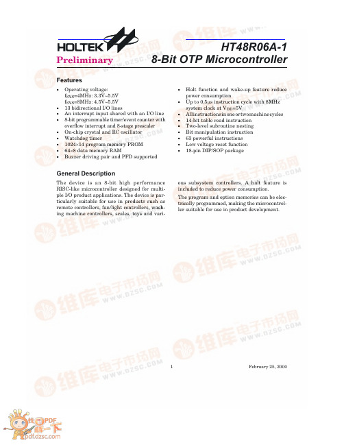
HT48R06A-18-Bit OTP Microcontroller1February 25,2000General DescriptionThe device is an 8-bit high performance RISC-like microcontroller designed for multi-ple I/O product applications.The device is par-ticularly suitable for use in products such as remote controllers,fan/light controllers,wash-ing machine controllers,scales,toys and vari-ous subsystem controllers.A halt feature is included to reduce power consumption.The program and option memories can be elec-trically programmed,making the microcontrol-ler suitable for use in product development.Features·Operating voltage:f SYS =4MHz:3.3V~5.5V f SYS =8MHz:4.5V~5.5V ·13bidirectional I/O lines·An interrupt input shared with an I/O line ·8-bit programmable timer/event counter with overflow interrupt and 8-stage prescaler ·On-chip crystal and RC oscillator ·Watchdog timer·1024´14program memory PROM ·64´8data memory RAM·Buzzer driving pair and PFD supported·Halt function and wake-up feature reduce power consumption·Up to 0.5m s instruction cycle with 8MHz system clock at V DD =5V·Allinstructionsinoneortwomachinecycles ·14-bit table read instruction ·Two-level subroutine nesting ·Bit manipulation instruction ·63powerful instructions ·Low voltage reset function ·18-pin DIP/SOP packagePreliminary查询HT48R06A-1供应商捷多邦,专业PCB打样工厂,24小时加急出货Block DiagramPin Assignment2February25,2000Pin DescriptionPin No.Pin Name I/O ROM CodeOption Description4~118~15PA0~PA7I/O Pull-high*Wake-upBidirectional8-bit input/output port.Each bit can beconfigured as wake-up input by ROM code option.Software instructions determine the CMOS output orschmitt trigger input with a pull-high resistor(deter-mined by pull-high options).7 6 5PB0/BZPB1/BZPB2I/OPull-high*I/O orBZ/BZBidirectional3-bit input/output port.Software in-structions determine the CMOS output or schmitttrigger input with a pull-high resistor(determined bypull-high options).The PB0and PB1are pin-shared with the BZ and BZ,respectively.Once the PB0and PB1are selected asbuzzer driving outputs,the output signals come froman internal PFD generator(shared with timer/eventcounter).8VSS¾¾Negative power supply,ground9 10PC0/INTPC1/TMR I/O Pull-high*Bidirectional I/O lines.Software instructions deter-mine the CMOS output or SCHMITT trigger inputwith a pull-high resistor(determined by pull-high op-tions).The external interrupt and timer input arepin-shared with the PC0and PC1,respectively.Theexternal interrupt input is activated on a high to lowtransition.11RES I¾Schmitt trigger reset input.Active low 12VDD¾¾Positive power supply13 14OSC1OSC2IOCrystalor RCOSC1,OSC2are connected to an RC network or Crys-tal(determined by ROM code option)for the internalsystem clock.In the case of RC operation,OSC2is theoutput terminal for1/4system clock.*All pull-high resistors are controlled by an option bit.Absolute Maximum RatingsSupply Voltage...............V SS-0.3V to V SS+5.5V Storage Temperature.................-50°C to125°C Input Voltage.................V SS-0.3V to V DD+0.3V Operating Temperature..............-40°C to85°CNote:These are stress ratings only.Stresses exceeding the range specified under"Absolute Maxi-mum Ratings"may cause substantial damage to the device.Functional operation of this device at other conditions beyond those listed in the specification is not implied and prolonged expo-sure to extreme conditions may affect device reliability.3February25,2000D.C.Characteristics Ta=25°CSymbol ParameterTest ConditionsMin.Typ.Max.Unit V DD ConditionsV DD1Operating Voltage¾f SYS=4MHz 3.3¾ 5.5V V DD2Operating Voltage¾f SYS=8MHz 4.5¾ 5.5VI DD1Operating Current(Crystal OSC)3.3VNo load,f SYS=4MHz¾12mA 5V¾24mAI DD2Operating Current(RC OSC)3.3VNo load,f SYS=4MHz¾12mA 5V¾24mAI DD3Operating Current(Crystal OSC)5V No load,fsys=8MHz¾510mAI STB1Standby Current(WDT Enabled)3.3VNo load,system Halt¾¾5m A 5V¾¾10m AI STB2Standby Current(WDT Disabled)3.3VNo load,system Halt¾¾1m A 5V¾¾2m AV IL1Input Low Voltage forI/O Ports,TMR and INT 3.3V¾0¾0.2V DD V 5V¾0¾0.2V DD VV IH1Input High Voltage forI/O Ports,TMR and INT 3.3V¾0.8V DD¾V DD V 5V¾0.8V DD¾V DD VV IL3Input Low Voltage(RES)3.3V¾0¾0.4V DD V 5V¾0¾0.4V DD VV IH3Input High Voltage(RES)3.3V¾0.9V DD¾V DD V 5V¾0.9V DD¾V DD VV LVR Low Voltage Reset¾¾ 3.1 3.2 3.3VI OL I/O Port Sink Current 3.3V V OL=0.1V DD48¾mA 5V V OL=0.1V DD1020¾mAI OH I/O Port SourceCurrent 3.3V V OH=0.9V DD-2-4¾mA 5V V OH=0.9V DD-5-10¾mAR PH Pull-high Resistance 3.3V¾406080k W 5V¾103050k W4February25,2000A.C.Characteristics Ta=25°CSymbol ParameterTest ConditionsMin.Typ.Max.Unit V DD Conditionsf SYS1System Clock(Crystal OSC)3.3V¾400¾4000kHz 5V¾400¾8000kHzf SYS2System Clock(RC OSC)3.3V¾400¾4000kHz 5V¾400¾4000kHzf TIMER Timer I/P Frequency(TMR)3.3V¾0¾4000kHz 5V¾0¾4000kHzt WDTOSC Watchdog Oscillator 3.3V¾4386168m s 5V¾3565130m st WDT1Watchdog Time-out Period(RC)3.3V Without WDTprescaler112243ms 5V91735mst WDT2Watchdog Time-out Period(System Clock)¾Without WDTprescaler¾1024¾t SYSt RES External Reset Low PulseWidth¾¾1¾¾m st SST System Start-up TimerPeriod¾Power-up,reset orwake-up from Halt¾1024¾t SYSt INT Interrupt Pulse Width¾¾1¾¾m s5February25,2000Functional DescriptionExecution flowThe system clock for the microcontroller is de-rived from either a crystal or an RC oscillator. The system clock is internally divided into four non-overlapping clocks.One instruction cycle consists of four system clock cycles. Instruction fetching and execution are pipelined in such a way that a fetch takes an in-struction cycle while decoding and execution takes the next instruction cycle.However,the pipelining scheme causes each instruction to ef-fectively execute in a cycle.If an instruction changes the program counter,two cycles are re-quired to complete the instruction.Program counter-PCThe program counter(PC)controls the se-quence in which the instructions stored in pro-gram PROM are executed and its contents specify full range of program memory.After accessing a program memory word to fetch an instruction code,the contents of the program counter are incremented by one.The program counter then points to the memory word contain-ing the next instruction code.When executing a jump instruction,conditional skip execution,loading PCL register,subrou-tine call,initial reset,internal interrupt,exter-nal interrupt or return from subroutine,the PC manipulates the program transfer by loading the address corresponding to each instruction. The conditional skip is activated by instruc-tions.Once the condition is met,the next in-struction,fetched during the current instruction execution,is discarded and a dummy cycle replaces it to get the proper in-struction.Otherwise proceed with the next in-struction.The lower byte of the program counter(PCL)is a readable and writable register(06H).Moving data into the PCL performs a short jump.The destination will be within256locations. When a control transfer takes place,an addi-tional dummy cycle is required.Program memory-PROMThe program memory is used to store the pro-gram instructions which are to be executed.It also contains data,table,and interrupt entries, and is organized into1024´14bits,addressed by the program counter and table pointer.Execution flow6February25,2000Certain locations in the program memory are reserved for special usage:·Location000HThis area is reserved for program initializa-tion.After chip reset,the program always be-gins execution at location000H.·Location004HThis area is reserved for the external inter-rupt service program.If the INT input pin is activated,the interrupt is enabled and the stack is not full,the program begins execution at location004H.·Location008HThis area is reserved for the timer/event coun-ter interrupt service program.If a timer inter-rupt results from a timer/event counteroverflow,and if the interrupt is enabled and the stack is not full,the program begins execution at location008H.·Table locationAny location in the PROM space can be used as look-up tables.The instructions"TABRDC [m]"(the current page,1page=256words) and"TABRDL[m]"(the last page)transfer the contents of the lower-order byte to the specified data memory,and the higher-order byte to TBLH(08H).Only the destination of the lower-order byte in the table is well-defined,the other bits of the table word are transferred to the lower portion of TBLH, and the remaining2bits are read as"0".The Table Higher-order byte register(TBLH)is read only.The table pointer(TBLP)is a read/write register(07H),which indicates the table location.Before accessing the table,the location must be placed in TBLP.The TBLH is read only and cannot be restored.If the main routine and the ISR(Interrupt ServiceModeProgram Counter*9*8*7*6*5*4*3*2*1*0Initial Reset0000000000 External Interrupt0000000100 Timer/Event Counter Overflow0000001000 Skip PC+2Loading PCL*9*8@7@6@5@4@3@2@1@0 Jump,Call Branch#9#8#7#6#5#4#3#2#1#0 Return from Subroutine S9S8S7S6S5S4S3S2S1S0Program counterNote:*9~*0:Program counter bits S9~S0:Stack register bits#9~#0:Instruction code bits@7~@0:PCL bitsProgram memory7February25,20008February 25,2000Instruction Table Location*9*8*7*6*5*4*3*2*1*0TABRDC [m]P9P8@7@6@5@4@3@2@1@0TABRDL [m]11@7@6@5@4@3@2@1@0Table locationNote:*9~*0:Table location bitsP9,P8:Current program counter bits@7~@0:Table pointer bitsRoutine)both employ the table read instruc-tion,the contents of the TBLH in the main routine are likely to be changed by the table read instruction used in the ISR.Errors can occur.In other words,using the table read in-struction in the main routine and the ISR si-multaneously should be avoided.However,if the table read instruction has to be applied in both the main routine and the ISR,the inter-rupt is supposed to be disabled prior to the ta-ble read instruction.It will not be enabled until the TBLH has been backed up.All table related instructions require two cycles to com-plete the operation.These areas may function as normal program memory depending upon the requirements.Stack register -STACKThis is a special part of the memory which is used to save the contents of the program coun-ter (PC)only.The stack is organized into 2lev-els and is neither part of the data nor part of the program space,and is neither readable nor writable.The activated level is indexed by the stack pointer (SP)and is neither readable nor writeable.At a subroutine call or interrupt ac-knowledgment,the contents of the program counter are pushed onto the stack.At the end of a subroutine or an interrupt routine,signaled by a return instruction (RET or RETI),the pro-gram counter is restored to its previous value from the stack.After a chip reset,the SP will point to the top of the stack.If the stack is full and a non-masked interrupt takes place,the interrupt request flag will be recorded but the acknowledgment will be inhib-ited.When the stack pointer is decremented (by RET or RETI),the interrupt will be serviced.This feature prevents stack overflow allowing the programmer to use the structure more eas-ily.In a similar case,if the stack is full and a "CALL"is subsequently executed,stack over-flow occurs and the first entry will be lost (only the most recent 2return addresses are stored).Data memory -RAMThe data memory is designed with 81´8bits.The data memory is divided into two func-tional groups:special function registers and general purpose data memory (64´8).Most are read/write,but some are read only.The special function registers include the indi-rect addressing register (00H),timer/event counter (TMR;0DH),timer/event counter con-trol register (TMRC;0EH),program counter lower-order byte register (PCL;06H),memory pointer register (MP;01H),accumulator (ACC;05H),table pointer (TBLP;07H),table higher-order byte register (TBLH;08H),status register (STATUS;0AH),interrupt control reg-ister (INTC;0BH),watchdog timer option set-ting register (WDTS;09H),I/O registers (PA;12H,PB;14H,PC;16H)and I/O control registers (PAC;13H,PBC;15H,PCC;17H).The remaining space before the 40H is reserved for future expanded usage and reading these loca-tions will get "00H".The general purpose data memory,addressed from 40H to 7FH,is used for data and control information under in-struction commands.All of the data memory areas can handle arith-metic,logic,increment,decrement and rotate operations directly.Except for some dedicated bits,each bit in the data memory can be set and reset by"SET[m].i"and"CLR[m].i".They are also indirectly accessible through memory pointer register(MP;01H).Indirect addressing registerLocation00H is an indirect addressing register that is not physically implemented.Any read/write operation of[00H]accesses data mem-ory pointed to by MP(01H).Reading location00H itself indirectly will return the result00H.Writ-ing indirectly results in no operation.The memory pointer register MP(01H)is a7-bit register.The bit7of MP is undefined and reading will return the result1.Any writing operation to MP will only transfer the lower7-bit data to MP.AccumulatorThe accumulator is closely related to ALU oper-ations.It is also mapped to location05H of the data memory and can carry out immediate data operations.The data movement between two data memory locations must pass through the accumulator.Arithmetic and logic unit-ALUThis circuit performs8-bit arithmetic and logic operations.The ALU provides the following func-tions:Arithmetic operations(ADD,ADC,SUB,SBC, DAA)·Logic operations(AND,OR,XOR,CPL)Rota-tion(RL,RR,RLC,RRC)·Increment and Decrement(INC,DEC)·Branch decision(SZ,SNZ,SIZ,SDZ....) The ALU not only saves the results of a data op-eration but also changes the status register. Status register-STATUSThis8-bit register(0AH)contains the zero flag (Z),carry flag(C),auxiliary carry flag(AC), overflow flag(OV),power down flag(PD),andwatchdog time-out flag(TO).It also records the status information and controls the operation sequence.With the exception of the TO and PD flags, bits in the status register can be altered by instructions like most other registers.Any data written into the status register will not change the TO or PD flag.In addition opera-RAM mapping9February25,2000tions related to the status register may give different results from those intended.The TO flag can be affected only by system power-up,a WDT time-out or executing the "CLR WDT"or"HALT"instruction.The PD flag can be affected only by executing the "HALT"or"CLR WDT"instruction or a sys-tem power-up.The Z,OV,AC and C flags generally reflect the status of the latest operations.In addition,on entering the interrupt sequence or executing the subroutine call,the status reg-ister will not be pushed onto the stack automat-ically.If the contents of the status are important and if the subroutine can corrupt the status register,precautions must be taken to save it properly.InterruptThe device provides an external interrupt and internal timer/event counter interrupts.The Interrupt Control Register(INTC;0BH)con-tains the interrupt control bits to set the en-able/disable and the interrupt request flags. Once an interrupt subroutine is serviced,all the other interrupts will be blocked(by clearing the EMI bit).This scheme may prevent any fur-ther interrupt nesting.Other interrupt re-quests may happen during this interval but only the interrupt request flag is recorded.If a certain interrupt requires servicing within the service routine,the EMI bit and the correspond-ing bit of INTC may be set to allow interrupt nesting.If the stack is full,the interrupt request will not be acknowledged,even if the related in-terrupt is enabled,until the SP is decremented. If immediate service is desired,the stack must be prevented from becoming full.All these kinds of interrupts have a wake-up ca-pability.As an interrupt is serviced,a control transfer occurs by pushing the program counter onto the stack,followed by a branch to a sub-routine at specified location in the program memory.Only the program counter is pushed onto the stack.If the contents of the register or status register(STATUS)are altered by the in-terrupt service program which corrupts the de-sired control sequence,the contents should be saved in advance.External interrupts are triggered by a high to low transition of INT and the related interruptLabels Bits FunctionC0C is set if the operation results in a carry during an addition operation or if a bor-row does not take place during a subtraction operation;otherwise C is cleared.C is also affected by a rotate through carry instruction.AC1AC is set if the operation results in a carry out of the low nibbles in addition or no borrow from the high nibble into the low nibble in subtraction;otherwise AC is cleared.Z2Z is set if the result of an arithmetic or logic operation is zero;otherwise Z is cleared.OV3OV is set if the operation results in a carry into the highest-order bit but not a carry out of the highest-order bit,or vice versa;otherwise OV is cleared.PD4PD is cleared by system power-up or executing the"CLR WDT"instruction.PD is set by executing the"HALT"instruction.TO5TO is cleared by system power-up or executing the"CLR WDT"or"HALT"in-struction.TO is set by a WDT time-out.¾6Undefined,read as"0"¾7Undefined,read as"0"Status register10February25,2000request flag(EIF;bit4of INTC)will be set. When the interrupt is enabled,the stack is not full and the external interrupt is active,a sub-routine call to location04H will occur.The in-terrupt request flag(EIF)and EMI bits will be cleared to disable other interrupts.The internal timer/event counter interrupt is initialized by setting the timer/event counter interrupt request flag(TF;bit5of INTC), caused by a timer overflow.When the interrupt is enabled,the stack is not full and the TF bit is set,a subroutine call to location08H will occur. The related interrupt request flag(TF)will be reset and the EMI bit cleared to disable further interrupts.During the execution of an interrupt subroutine, other interrupt acknowledgments are held until the"RETI"instruction is executed or the EMI bit and the related interrupt control bit are set to 1(of course,if the stack is not full).To return from the interrupt subroutine,"RET"or"RETI" may be invoked.RETI will set the EMI bit to en-able an interrupt service,but RET will not. Interrupts,occurring in the interval between the rising edges of two consecutive T2pulses, will be serviced on the latter of the two T2 pulses,if the corresponding interrupts are en-abled.In the case of simultaneous requests the following table shows the priority that is ap-plied.These can be masked by resetting the EMI bit.No.Interrupt Source Priority Vectora External Interrupt104Hb Timer/eventCounter Overflow208H The timer/event counter interrupt request flag (TF),external interrupt request flag(EIF),en-able timer/event counter bit(ETI),enable ex-ternal interrupt bit(EEI)and enable master interrupt bit(EMI)constitute an interrupt con-trol register(INTC)which is located at0BH in the data memory.EMI,EEI,ETI are used to control the enabling/disabling of interrupts. These bits prevent the requested interrupt from being serviced.Once the interrupt request flags(TF,EIF)are set,they will remain in the INTC register until the interrupts are serviced or cleared by a software instruction.It is recommended that a program does not use the"CALL subroutine"within the inter-rupt subroutine.Interrupts often occur in an unpredictable manner or need to be serviced immediately in some applications.If only one stack is left and enabling the interrupt is not well controlled,the original control sequence willRegister Bit bel FunctionINTC (0BH)0EMI Controls the master(global)interrupt(1=enabled;0=disabled)1EEI Controls the external interrupt(1=enabled;0=disabled)2ETI Controls the timer/event counter interrupt(1=enabled;0=disabled)3¾Unused bit,read as"0"4EIF External interrupt request flag(1=active;0=inactive)5TF Internal timer/event counter request flag(1=active;0=inactive)6¾Unused bit,read as"0"7¾Unused bit,read as"0"INTC register11February25,2000be damaged once the"CALL"operates in the in-terrupt subroutine.Oscillator configurationThere are two oscillator circuits in the microcontroller.Both are designed for system clocks,namely the RC oscillator and the Crystal oscillator, which are determined by the ROM code option. No matter what oscillator type is selected,the signal provides the system clock.The HALT mode stops the system oscillator and ignores an external signal to conserve power.If an RC oscillator is used,an external resistor between OSC1and VDD is required and the resistance must range from51k W to1M W.The system clock,divided by4,is available on OSC2,which can be used to synchronize exter-nal logic.The RC oscillator provides the most cost effective solution.However,the frequency of oscillation may vary with VDD,tempera-tures and the chip itself due to process varia-tions.It is,therefore,not suitable for timing sensitive operations where an accurate oscilla-tor frequency is desired.If the Crystal oscillator is used,a crystal across OSC1and OSC2is needed to provide the feed-back and phase shift required for the oscillator, and no other external components are required. Instead of a crystal,a resonator can also be con-nected between OSC1and OSC2to get a fre-quency reference,but two external capacitors in OSC1and OSC2are required(If the oscillat-ing frequency is less than1MHz).The WDT oscillator is a free running on-chip RC oscillator,and no external components are re-quired.Even if the system enters the power down mode,the system clock is stopped,but the WDT oscillator still works with a period of approxi-mately65m s/5V.The WDT oscillator can be dis-abled by ROM code option to conserve power.Watchdog timer-WDTThe clock source of WDT is implemented by a dedicated RC oscillator(WDT oscillator)or in-struction clock(system clock divided by4),de-cided by ROM code option.This timer is designed to prevent a software malfunction or sequence from jumping to an unknown location with unpredictable results.The watchdog timer can be disabled by a ROM code option.If the watchdog timer is disabled,all the execu-tions related to the WDT result in no operation. Once the internal WDT oscillator(RC oscillator with a period of65m s/5V normally)is selected,it is first divided by256(8-stage)to get the nomi-nal time-out period of approximately 16.6ms/5V.This time-out period may vary with temperatures,VDD and process variations.By invoking the WDT prescaler,longer time-out periods can be realized.Writing data to WS2, WS1,WS0(bit2,1,0of the WDTS)can give differ-ent time-out periods.If WS2,WS1,and WS0are all equal to1,the division ratio is up to1:128,andSystem oscillatorWatchdog timer12February25,2000the maximum time-out period is2.2s/5V seconds. If the WDT oscillator is disabled,the WDT clock may still come from the instruction clock and op-erate in the same manner except that in the HALT state the WDT may stop counting and lose its protecting purpose.In this situation the logic can only be restarted by external logic.The high nibble and bit3of the WDTS are reserved for user's defined flags,which can be used to indicate some specified status.If the device operates in a noisy environment,us-ing the on-chip RC oscillator(WDT OSC)is strongly recommended,since the HALT will stop the system clock.WS2WS1WS0Division Ratio0001:10011:20101:40111:81001:161011:321101:641111:128WDTS registerThe WDT overflow under normal operation will initialize"chip reset"and set the status bit "TO".But in the HALT mode,the overflow will initialize a²warm reset²,and only the PC and SP are reset to zero.To clear the contents of WDT(including the WDT prescaler),three methods are adopted;external reset(a low level to RES),software instruction and a"HALT"in-struction.The software instruction include "CLR WDT"and the other set-"CLR WDT1" and"CLR WDT2".Of these two types of instruc-tion,only one can be active depending on the ROM code option-"CLR WDT times selection option".If the"CLR WDT"is selected(i.e. CLRWDT times equal one),any execution of the"CLR WDT"instruction will clear the WDT. In the case that"CLR WDT1"and"CLR WDT2" are chosen(i.e.CLRWDT times equal two), these two instructions must be executed to clear the WDT;otherwise,the WDT may reset the chip as a result of time-out.Power down operation-HALTThe HALT mode is initialized by the"HALT"in-struction and results in the following...·The system oscillator will be turned off butthe WDT oscillator keeps running(if theWDT oscillator is selected).·The contents of the on chip RAM and regis-ters remain unchanged.·WDT and WDT prescaler will be cleared andrecounted again(if the WDT clock is from theWDT oscillator).·AlloftheI/Oportsmaintaintheiroriginalstatus.·The PD flag is set and the TO flag is cleared.The system can leave the HALT mode by means of an external reset,an interrupt,an external falling edge signal on port A or a WDT overflow.An external reset causes a device initialization and the WDT overflow performs a"warm re-set".After the TO and PD flags are examined, the reason for chip reset can be determined.The PD flag is cleared by system power-up or executing the"CLR WDT"instruction and is set when executing the"HALT"instruction.The TO flag is set if the WDT time-out occurs,and causes a wake-up that only resets the PC and SP;the others keep their original status.The port A wake-up and interrupt methods can be considered as a continuation of normal exe-cution.Each bit in port A can be independently selected to wake up the device by the ROM code option.Awakening from an I/O port stimulus, the program will resume execution of the next instruction.If it is awakening from an inter-rupt,two sequences may happen.If the related interrupt is disabled or the interrupt is enabled but the stack is full,the program will resume execution at the next instruction.If the inter-rupt is enabled and the stack is not full,the reg-ular interrupt response takes place.If an interrupt request flag is set to"1"before enter-ing the HALT mode,the wake-up function of the related interrupt will be disabled.Once a wake-up event occurs,it takes1024t SYS(sys-tem clock period)to resume normal operation.In other words,a dummy period will be inserted after wake-up.If the wake-up results from an interrupt acknowledgment,the actual inter-rupt subroutine execution will be delayed by one or more cycles.If the wake-up results in the13February25,2000。
The human resource managementIntroduction:Human resources are the most valuable and unique assets of an organization. The successful management of an organization's human resources is an exciting, dynamic and challenging task, especially at a time when the world has become a global village and economies are in a state of flux. The scarcity of talented resources and the growing expectations of the modern day worker have further increased the complexity of the human resource function. Even though specific human resource functions/activities are the responsibility of the human resource department, the actual management of human resources is the responsibility of all the managers in an organization.It is therefore necessary for all managers to understand and give due importance to the different human resource policies and activities in the organization. Human Resource Management outlines the importance of HRM and its different functions in an organization. It examines the various HR processes that are concerned with attracting, managing, motivating and developing employees for the benefit of the organization.Content:Job Analysis:Job analysis is a systematic of the activities within a job. It is a technical procedure one that is used to define the duties, responsibilities and accountabilities of a job. It involves the identification and description of what is happening on the required tasks, the knowledge and skills necessary for performing them and condition under which they must be performed now and in the future. Job analysis facilitates accurate recruitment and selection practices, sets standards for performance appraisals and allows appropriate classification of positions.Job description:Job descriptions are based on objective information obtained through job analysis, an understanding of the competencies and skills required to accomplish needed tasks, and the needs of the organization to produce work.Job descriptions clearly identify and spell out the responsibilities of a specific job. Job descriptions also include information about working conditions, tools, equipment used, knowledge and skills needed, and relationships with other positions.The best job descriptions are living, breathing documents that are updated as responsibilities change. The best job descriptions do not limit employees, but rather, cause them to stretch their experience, grow their skills, and develop their ability to contribute within their organization.Job specification:A job specification describes the knowledge, skills, education, experience, and abilities you believe are essential to performing a particular job. The job specification is developed from the job analysis. Ideally, also developed from a detailed job description, the job specification describes the person you want to hire for a particular job.A job specification cuts to the quick with your requirements whereas the job description defines the duties and requirements of an employee’s job in detail. The job specification provides detailed characteristics, knowledge, education, skills, and experience needed to perform the job, with an overview of the specific job requirements.Like The Experience: experience in the job you are seeking to fill. Number of years requires progressively more complex and responsible experience, and supervisory or managerial experience.Like The Education: State what degrees, such as training, or certifications are required for the position.The Recruitment:Recruitment is a process to discover the sources of manpower to meet the requirements of the staffing schedule and to employ effective measures for attracting that manpower in adequate numbers to facilitate effective selection of an efficient working force.1-Recruitment Strategy:You need a strategic plan in order to find and select the right people.Do the following.•Carry out a regular inventory of the employment needs of every department, division and section in your organization. Carry out this exercise at least once ayear. This provides you with information on the immediate and the short-termneeds for additional manpower. This is manpower needs analysis.•Gather information from your organizational strategic plan. You will find information on the need for additional people and the most likely areas fordeployment.•Scrutinize management decisions and interpret them in terms of manpower management and the needs for additional manpower.•Keep abreast of new developments in the industry in which your organization is in, the prevailing market conditions and what competitors are doing. You mayneed to create new positions.Alertness to important matters occurring within your organization and those in the external environment is essential. This will enable you to review your plan.2-Recruitment Process Future:The recruitment process is the HR Process, which has to react to the challenges coming from the external job market and the internal changes in the organization. The recruitment process is flexible and HRM Function has to make proper recruitment analyses and changes in the recruitment process design.The challenge for the recruitment process is the elderly population. The recruitment process is currently focused on the young graduates and employees with limited work experience, but the future of the recruitment process is about older job candidates. The selection procedure has to be adjusted to fit the needs of older potential candidates. The tests and assessments working for young graduates are not suitable for the older potential employees. Also the focus on the young graduates has to be changes to cover the more wide range of the job candidates.The job market gets more competitive. The employees get less loyal with the organization and keeping employees in touch with the employer is harder every day. The organizations get more aggressive in the search of the good potential. Theorganizations spend more money on executive search consulting services and the final result is uncertain. The organization has to develop more clever approach to reach the best potential on the job market and better ways of protecting their own potential inside the organization. The organization with the best supply of the potential from the job market will be the winner in the long term competition on the market.The recruitment process future is in the shortening the time to fill measure. The job candidates get less patient with the length of the recruitment process. They want the final decision as soon as possible and the HRM Function has to find more creative ways of hiring new employees. The job candidates get less patient with the response rate of the job market and the organization with the quickest response rate usually wins. The organizations are under a huge pressure to shorten the time to fill.Selection:Training:The training it divided two parts:*First services training:1-Safety TrainingSafety training is an important part of service manager training. There are many dangers present in an automotive dealership and managers must make the workplace as safe as possible. Vendors and consultants provide many options for safety training and your internal training department may also have programs available for training. The key is to make certain every employee receives and participates in the training and that your service managers are actively involved in that training. Modeling proper safety techniques ensures safety is a priority.2-People SkillsExcellent people skills are essential for success as a service manager. Listening and questioning skills programs are available from a variety of resources. Feedback techniques and motivational techniques are also an important element in service manager training programs. Managing employee performance, including documentation and performance review skills, must also be a part of all training for service managers.All people skills programs need to include ample time for practice and role plays. Practice in a workshop leads to performance back on the job.*Second training method:1-Traditional Method•The traditional apprenticeship method has been in existence since ancient times. While this method has evolved over the years, the primary objective is to provide the necessary education to get the job done. Presentation techniquesare popular when using this method. The learners receive explicit instruction on new information and then they practice what they have learned throughstructured exercises and on the job training. The traditional training method ismost cost effective when leaders are being required to attain new knowledgeand immediately implement new skills.2-Discovery Method•The discovery method requires that managers have a fundamental knowledge of the topic prior to training. During the training, this method incorporates themanagers interacting with their environment by exploring and manipulatingobjects, wrestling with questions and controversies, and performing specificexperiments. The discovery method is most effective when managers need todevelop critical thinking, problem solving, research skills, and collaborative fresh perspectives.Performance Appraisal:1-Human resource management performance appraisal Todays businesses are under a great deal of pressure to perform. With increasing customer expectations, global competition, and costs of goods and services, many companies struggle to meet profit forecasts. As a result, companies are beginning to discover the powerful link that exists between employee performance and financial success. Many companies are relying more heavily on human capital to address consumer demands while lowering operating costs, and improving financial position. Deploying employee performance appraisal programs that lead to measurable improvements in employee performance can provide the human capital leverage companies need to overcome many of today’s business obstacles. Companies. The key to a successful performance appraisal is clear communication, accurate information and flawless execution. Employees generally feel more motivated, empowered and appreciated when performance appraisals areexecuted properly. As a result, employers realize the benefits associated with higher productivity levels, increased employee performance and improved quality results. Performance appraisals can help to increase employees’ support of company goals and objectives. An appraisal that contains clearly defined goals, objective measurements, and an accurate summary of the employees’ performance has a higher potential of increasing employee satisfaction and inspiring ongoing performance than appraisals that fail to support these elements. Although there are many steps that have proven to be effective in delivering successful outcomes, proactively communicating expectations, frequently following up, and properly aligning goals and objectives should never be omitted. Proactively communicating clearly defined expectations, goals and objectives to employees is one of the most important steps. Omitting this step often results in performance appraisals that are perceived by employees as ambiguous and unfair.2-Providing employees with regular feedback regarding their individual performance is another important step. However, communicating clear goals and objectives, but failing to provide employees with frequent and ongoing performance related feedback often results in less than favorable outcomes. Failure in this area has the highest potential of producing negative results in employee satisfaction, loyalty and performance. Frankly, this is a critical area where both the employee and the employer suffer equally. Another extremely important step in the performance appraisal process is the alignment of department-level goals and objectives with the companies overall business strategy. Generally, the human resources department holds the responsibility of assisting with the development of department-level goals and objectives.. Often, this area is commonly overlooked in both large and small organizations. A performance appraisal that only supports general elements rarely produces high-performing employees. How the appraisal is communicated to the employee, and how frequently the employee is given performance related feedback between appraisal periods play a significant role in the effectiveness of the appraisal process. Poorly written and executed appraisals often result in employee dissatisfaction, reductions in productivity, and unwanted employee turnover. Failure to meet the employees expectations during the performance appraisal process can be disastrous. To achieve and sustain exceptional employee performance, companies must engage the irinternal resources, and then develop and execute a performance appraisal program that leads to a strong alliance between its human resources department, management team and most importantly, its employees. All three groups must have a clear understanding of every ones role, responsibilities and expectationsCompensation benefits:1-strategy:As we knowing the important strategies in the HRM function as it influences the costs of the organization and potential bad decision can lead to very serious damages to the organization and we can explain it via many parts:*sets the main objectives for the HRM Function, the compensation and benefits strategy has to follow. When the overall HRM Strategy states the low cost of services and employees, the compensation and benefits strategy cannot target the highest salaries at all levels.*sets the general rules for the compensation and benefits area in the organization and the owners and leaders of the area. In some organizations, the compensation and benefits department is just a support department for the line management.*sets the position of the organization on the job market and defines the items in the total cash in the organization and their role. The role of different components of the compensation is very important as the role of the compensation components can differ. For example, the role of bonuses can be primarily in performance reward or the retention of the employees and the organization has to decide.The compensation and benefits strategy has to reflect the reality in the industry and the surrounding job market. The compensation strategy can set the wish to pay the lowest possible salaries, but the HRM Function and the organization have to respect the reality on the job market and needs a strong support from the top management as it sets strong limits to the daily operation of the line management and they usually do not fully agree with all the aspects included in the compensation and benefits strategy and Compensation and Benefits is about setting the Compensation Strategy, monitoring other organizations on the market and a lot of internal analysis to ensure, the organization does not pay too much to its employees and it stays competitive on the job market.2-Base Salaries and Competitors:The managers believe, the employees leave the organization, because the competitor offers to them a higher base salary. Honestly, the employees are usually satisfied with their base salaries; they are not satisfied with their managers.The base salaries are always driven by the competition on the job market. The organizations compete for the talents on the job market and their base salaries have tobe competitive. The organizations monitor the job market and they adjust their base salaries according the job market.The organization, which is stable, tries to set its base salaries around the median of the job market. When the market salaries are not exactly known, the managers have to use their gut feeling to set the base salaries correctly.The competitors tend to pay similar base salaries to their employees. When the organization pays higher base salaries at the same job position, there is always some kind of the issue. The organization in troubles has to pay “a risk premium” to its employees as it needs urgently to solve its issue. The employees should be always warned, when they leave the organization for a better salary.The base salaries are the part of the competition on the job market and some organization makes the base salary their competitive advantage. Generally, this approach is very dangerous as the organization has to pay a higher proportion of its costs in personnel expenses and it can bring a huge disadvantage in the future.Conclusion:-advantage:-disadvantage:-opinions:。
H1 Supply chain management New Words and Phrasesoverview n. 概要upstream上游的,溯流而上的downstream adj.下游的linkage n. 连接ultimate adj.最终的arrangement n.排列,安排distributive 分发的,分配的integrated 综合的,完整的procurement n.获得,取得shareholder n. 股东utilization n. 利用optimization 最佳化,最优化mathematical a 数学的,精确的modeling n.建模,造型margin n.盈余,利润,毛额throughput生产量, 生产能力give rise to 引起,导致Facility设备,设备Procurement实现,获得Complexity 复杂的Objective 目标Throughput 产能Inventory 存货Pattern 方式Mechanism机械装置,机构,机制Unit单位carry on:经营,从事coordinated:协调例句1 There is a need for a mechanism through which these different functions can be integrated together.需要有一种使不同的功能整合在一起的机制。
练习:我们需要一个新的代理商以获得新的客户。
There is a need of a new agent through which we can find new customers.2 CM brings into a supply chain all business units of an enterprise to carry on a coordinated management.SCM将企业的所有经营单元纳入供应链从而实现协调管理。
Modeling a Service Function for Time-on-Task AllocationD. L. Kimbler, Ph.D., P.E.Department of Industrial EngineeringClemson UniversityClemson, SC 29634-0920Hrishikesh KarekarCSG SystemsOmaha, NE 68154AbstractProductivity improvement in service functions frequently require approaches different than the classic work design approach. This example involves structured data collection on work processes of a large number of people, regression to characterize key variables, and linear programming to develop a time-on-task allocation model. The validated model can then be used in a number of ways to guide re-design of work functions and time allocation to classes of tasks. Model validation provides guidance on need for model updating in future use.KeywordsService, time allocation, linear programming1. IntroductionA common problem in process improvement involves collecting data on work processes of a target group, analyzing the results and, based on the analysis, making recommendations for change. These studies take on a broad variety of forms depending on each set of contexts and goals. While development of useful models has become relatively routine in manufacturing and production, it is more difficult in service functions and the service sector.Effecting improvement in the service functions is certainly more difficult than in production work for a number of reasons which derive from the inherent differences between production and service work processes. A frequent approach involves studying, documenting, and analyzing individual work processes. Results of analysis then lead to modification of these work processes. The difficulties may arise because, rather than working to a formal process description or method, service workers work to provide functions or achieve goals. These service work processes may involve much greater independence of action and variety of method, leading to a possibly high level of variation in conventional process measurements. Issues in service process improvement are well known. [1,3]One approach to process change in service functions is to document time spent on service tasks and then provide guidance on desired or target time spent. This implies a process of:1. definition of key work process components and variables2. process study and data collection3. model development and validation4. implementation of change based on model resultsWhile direct contribution of work processes to productivity may easily be found in production systems, this is more difficult in service functions. It is important, then, in model development, to connect work processes to higher-level aggregate performance measures, such as financial data.These issues are illustrated through description of a process improvement study in a Fortune 500 distribution company. This company, which cannot be identified due to confidentiality constraints, distributes a wide variety of products through a network of sales representatives and distribution centers.The sales representatives operate in a number of different locations where they take customer orders, receive information requests, provide information, and perform a number of other tasks all related to serving as the primary contact between the company and its customers. Orders, information requests and other data are passed to other function in the company, eventually resulting in shipment of ordered goods to customers. In short, this is a typical multi-location conventional business-to-business sales and distribution organization.The focus of our study is the sales representative (SR) work process, and the objective is to progress from adequate description of current work processes to information leading to appropriate change in those processes. The challenges inherent in this study, given multiple workers of similar job description (but likely different execution) in each of several locations, are enormous. Due to the scope of this study and the confidentiality issues, this paper is limited to description of the issues of data collection and development and proposed use of a work process model which provides connection of processes to financial measures.2. Data CollectionData collection for process improvement studies in service functions can take many forms. Several earlier studies have documented the value of detailed data collection, including time study, work sampling, and motion analysis. [5,6] The approach in this study was time study using laptop computers and software developed specifically for this problem. Analysts observed each of 68 SR’s in 30 locations across four different company divisions. Each SR was observed for a period of one week.The study began with a pilot study, which led to development of the software for laptop data collection. The full study was then deployed to the 30 locations over a period of roughly three months. The structure of observation variables defined in the pilot study was reflected in the laptop software; results of individual studies were used to load a Microsoft Access database. This database could then be used in a number of ways to support different approaches to analysis.Clearly, this was an expensive approach to data collection. The expense was justified, in the minds of the executive responsible, due to the much higher information content of the resulting data and the potential gains through improvement. A critical function was the pilot study, which not only proved the feasibility of this approach, but also provided valuable information that was used to refine the process for use fully deployed across the company.3. The Fitted ModelThe first step in model development was to fit a model relating work activities of SR’s to an output measure. The measure chosen was Net Sales Entered (NSE), the dollar value of orders directly related to the business activity. A data cleaning process eliminated several observations which, in the analyst’s judgment, either contained errors or for some other operational reason were not representative. The remaining 48 observations were fit using step-wise linear regression. The result was a linear fit involving 17 independent variables with NSE as the response. This regression has an R-squared value of 79.1% and F-statistic of 6.69 with 17 numerator and 30 denominator degrees of freedom. This was almost as good as the fitted model including all variables (R-squared 82.4%) and has fewer variables contributing lower marginal information.The fitted model involving 17 variables was found to have no significant colinearity. Residuals were found to be approximately normally distributed, and almost all coefficients were found to be statistically significant at the 95% confidence level. All variance inflation factors were low (2.8 or less), and the predicted sum of squares and predicted R-square indicated a good model for prediction. [see 7]With multiple regression it is possible, in using the model for prediction, to inadvertently choose a set of independent variable values that lead to extrapolation outside the bounds of the data. Since part of our use of this model is for prediction, we wish to insure that we can detect when that prediction would involve extrapolation beyond the bounds of the original data. This can be checked using the matrixH=X(X`X)-1X`. The maximum value of the diagonal elements of H (h max ) for a point x i defines the boundary of a region defined by the regression data. A predicted value can be tested by calculating h 0=x 0(X`X)x 0` and comparing it to h max . Points whose h values are less than h max are within the ellipsoid defined by the original data, and thus consist of interpolation rather than extrapolation. This property can be used to insure that prediction does not stray outside the bounds of the original study.[2]4. The Improvement ModelOne approach to improvement is to define the allocation of time to tasks. The results of regression can be interpreted as the contribution rate of business activities to sales. Thus, one could interpret the fitted regression as an objective function involving NSE expressed as a function of time spent on businessactivities, each multiplied by a coefficient which corresponds to the rate of increase or decrease of NSE on some convenient time basis, such as minutes per week. This is a natural interpretation, as each observation was the composite of activities during a work week, and NSE was the recorded sales entered by the SR for that week, taken from data routinely collected by the company.Improvement implies some allocation other than the one in current use. A set of constraints selected to guide process change to achieve corporate goals would complete this linear model. One reasonable set of constraints could be based on the following:1. time spent in all activities = time available in one week2. time spent in non-value-added activities <= non-value-allocated maximum3. time spent in value-added activities <= time available in one week4. time spent in each activity => activity minimumThis gives rise to three aggregate constraints and one constraint for each activity. Time could be expressed in absolute or relative terms, given than consistency is maintained. Conventional non-negativity constraints complete the LP model. The classification of value-added and non-value-added activities is based on analyst judgment with respect to goals of the study.The complete model [4] is given as:i x a z i i ∀=∑maxsubject to∑=i i x 1∑∃≤j b x j i value added activities∑∃≤j b x j i non value added activitiesi b x j i ∀≥At optimality, the model gives us the times allocated to these tasks, consistent with corporate goals asexpressed in the constraints. This information could be used in a variety of ways. For example, the top few variables with the highest values could be given priority. Alternatively, variables could be grouped and their values summed. For example, one optimal solution and grouping would guide SR’s to allocate their time as follows:customer calls 60%data entry 16%delivery questions 4%field research 4%other 16%The optimal solution to the LP model provides the relative importance of the various activities. The managerial questions remains as to how this information should be reflected in guidance to SR’s and training.5. ConclusionThis research has dealt with the difficult problem of how best to allocate time to task for service functions. The solution method chosen began with data collection, used multiple linear regression to determine the relationships between sales entered and the various activities, and used linear programming to develop priorities for these activities.These priorities can be used to provide priorities to the sales representatives, and to guide development of training programs. If the overall objective is to change SR allocation of time to task, this research shows how the priorities can be developed based on time study and direct observation. Given these priorities, managerial control and training can be used intelligently to better align the work processes of sales representatives with corporate goals.5. Biographical SketchesD. L. Kimbler received his BSE in Industrial Engineering from University of South Florida, and MS and PhD from Virginia Tech. He is a Fellow of IIE and a registered professional engineer in South Carolina. Dr. Kimbler is a professor of industrial engineering at Clemson UniversityHrishikesh Karekar received his MS in Industrial Engineering from Clemson University. He is presently an industrial engineering with CSG Systems.References1. Best Practices in Performance Measurement, National Performance Review, June 19972. Graybill, Franklin A. and Hariharan K. Iyer, Regression Analysis: Concepts and Application, International Thomson Publications, 1993.3. Heskett, J. L., “Lessons In the Service Sector”, Harvard Business Review, 1987.4. Karekar, Hrishikesh, Linear Programming Approach for “Time to Task” Allocations for a Business Process in a Service Industry, unpublished MS thesis, Department of Industrial Engineering, 2001.5. Metters, R., Vargas, V., Organizing work in service firms. Business Horizons, 43, 4, July 2000,.6. Mclaughlin, C. and Coffey, S., Measuring productivity in services. International Journal of Service Industry Management, 1,1, 1990.7. Montgomery, Douglas C. and Elizabeth A. Peck, Introduction to Linear Regression Analysis, John Wiley and Sons, New York, 1982.。