cisco UC520资料
- 格式:pdf
- 大小:1014.74 KB
- 文档页数:40
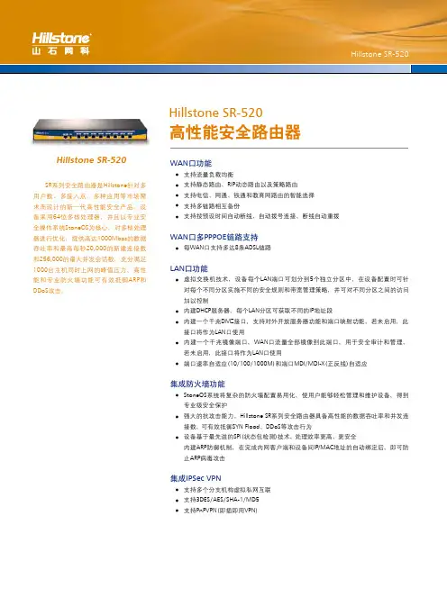
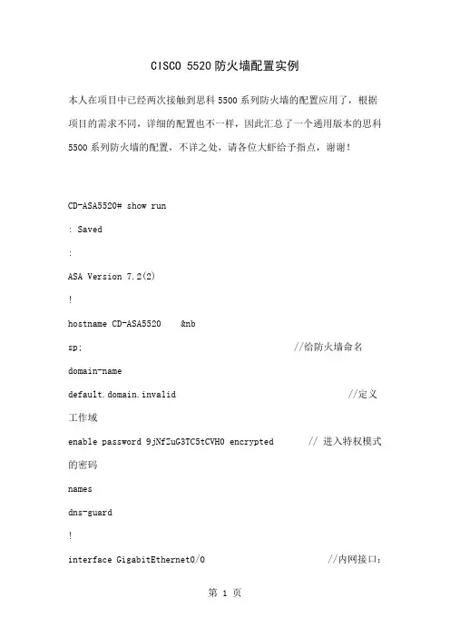
CISCO 5520防火墙配置实例本人在项目中已经两次接触到思科5500系列防火墙的配置应用了,根据项目的需求不同,详细的配置也不一样,因此汇总了一个通用版本的思科5500系列防火墙的配置,不详之处,请各位大虾给予指点,谢谢!CD-ASA5520# show run: Saved:ASA Version 7.2(2)!hostname CD-ASA5520 //给防火墙命名domain-namedefault.domain.invalid //定义工作域enable password 9jNfZuG3TC5tCVH0 encrypted // 进入特权模式的密码namesdns-guard!interface GigabitEthernet0/0 //内网接口:full //接口作工模式:全双工,半双,自适应nameif inside //为端口命名:内部接口insidesecurity-level 100 //设置安全级别 0~100 值越大越安全ip address 192.168.1.1 255.255.255.0 //设置本端口的IP地址!interface GigabitEthernet0/1 //外网接口nameif outside //为外部端口命名:外部接口outsidesecurity-level 0ip address 202.98.131.122 255.255.255.0 //IP地址配置!interface GigabitEthernet0/2nameif dmzsecurity-level 50ip address 192.168.2.1 255.255.255.0!interface GigabitEthernet0/3no nameifno security-levelno ip address!interface Management0/0 //防火墙管理地址shutdownno nameifno security-levelno ip address!passwd 2KFQnbNIdI.2KYOU encryptedftp mode passiveclock timezone CST 8dns server-group DefaultDNSdomain-name default.domain.invalidaccess-list outside_permit extended permit tcp any interface outside eq 3389//访问控制列表access-list outside_permit extended permit tcp any interface outside range 30000 30010//允许外部任何用户可以访问outside 接口的30000-30010的端口。
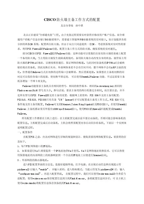
CISCO 防火墙主备工作方式的配置北京办事处孙中祺北京正在建设”全球通充值”工程而全球通用户的帐户信息存储于BOSS系统中原计划提供负荷分担的两条2M系统但由于局方只同意提供一套2MÀûÓÃFIX Firewall的Failover功能确保系统的实时通信这种功能可以使我们在原有防火墙的基础上配置一个备用防火墙备用防火墙自动改变自身的状态以继续维持通信与此同时原备机的IP和MAC会被映射给现在的备机外部网络来看不会有任何不同但普通的failover方式在切换的过程端口会被释放如果想在主备机切换的同时还可以保持各端口的连接可以使用Stateful Failover 功能Failover功能要求主备机具有相同的型号相同的Actovationg key,相同的Flash memory,RAM型号及大小要求主备用的两台机器完全相同并不是所有型号的FIX Firewall都支持主备用设置PIX 506不支持主备用配置PIX525UR PIX 520 可无条件地支持主备用配置若使用Stateful Failover ,主备机都必须另外装有100Mbps Ethernet接口所有配置工作都要在主机上进行否则可能会影响备机的 配置信息主机会将所需配置内容自动同步给备机一应该对网络进行详细的规划和设计要获得的信息如下每个PIX网络接口的IP地址 如果要进行NAT,则要提供一个IP地址池供NAT使用它可以将使用保留地址的内部网段上的机器映射到一个合法的IP地址上以便进行Internet访问外部网段的路由器地址连接好超级终端在出现启动信息和出现提示符pixfirewall>后输入进入特权模式输入在配置过程中使用write memory保存配置信息到主机Flash Memory¿É 在主机上使用write standby将配置信息保存到备机的Flash Memory本例中网络规划如下配置步骤1网络接口的配置PIX使用nameif和ip address命令进行网络接口配置nameif ethernet1 outside security0nameif ethernet0 inside security100PIX防火墙使用Intel的10/100Mbps网卡interface ethernet0 autointerface ethernet1 auto最后ip address inside 139.100.12.201 255.255.252.0ip address outside 198.115.153.51 255.255.255.03ÎÒÃǶ¨ÒåÁËÄÚ²¿Íø¶Î°²È«ÖµÎª100用户在安全值高的区域访问安全值低的区域相反地则需要使用static和conduit命令两个语句中的NAT ID应一样第二句定义NAT使用的地址池合法的IP地址并不多4route outside 198.115.55.0 255.255.255.0 198.115.153.1198.115.153.1是内部网段访问198.115.55.0所要经过的路由器地址允许使用ICMP协议conduit permit icmp any any此命令允许在内部网段和外部网段使用ICMP协议内外网段可以使用ping命令和ftp命令增加telnet访问控制在PIX中telnet 139.100.12.0 255.255.252.0telnet 198.115.153.0 255.255.255.0即允许139.100.12.0和198.115.153.0网段器使用telnet访问防火墙当访问防火墙的机器5分钟内没有任何操作时telnet访问的缺省口令是cisco测试telnet时7PIX拒绝所有来自外部网段的访问请求为了使外部网络上的用户可以访问到以下是允许外部网络访问内部网络上的服务器的命令第一个命令将在内部网段的服务器139.100.12.140映射成外部合法地址198.115.153.538Active time: 82140 (sec)Interface inside (139.100.12.201): Normal (Waiting)Interface outside (198.115.153.51): Normal (Waiting)Other host: Secondary - StandbyActive time: 0 (sec)Interface inside (139.100.12.202): Normal (Waiting)Interface outside (198.115.153.52): Normal (Waiting)Stateful Failover Logical Update StatisticsLink : Unconfigured.表示配置成功三注意线是有方向性的将标有secondary的一端连于备机连接状态如图所示在打开备机电源前应保证备机上没有任何配置信息用config erase命令清除配置信息打开电源在主机上使用show ip 和show failover命令应该看到如下信息bj_uc1# show ipSystem IP Addresses:ip address inside 139.100.12.201 255.255.252.0ip address outside 198.115.153.51 255.255.255.0 Current IP Addresses:ip address inside 139.100.12.201 255.255.252.0ip address outside 198.115.153.51 255.255.255.0bj_uc1# show failoverFailover OnCable status: NormalReconnect timeout 0:00:00Poll frequency 15 secondsThis host: Primary - ActiveActive time: 82140 (sec)Interface inside (139.100.12.201): NormalInterface outside (198.115.153.51): NormalOther host: Secondary - StandbyActive time: 0 (sec)Interface inside (139.100.12.202): NormalInterface outside (198.115.153.52): NormalStateful Failover Logical Update StatisticsLink : Unconfigured.在备机上使用show ip和show failover命令应该看到如下信息bj_uc1# show ipSystem IP Addresses:ip address inside 139.100.12.201 255.255.252.0ip address outside 198.115.153.51 255.255.255.0 Current IP Addresses:ip address inside 139.100.12.202 255.255.252.0ip address outside 198.115.153.52 255.255.255.0bj_uc1# show failoverFailover OnCable status: NormalReconnect timeout 0:00:00Poll frequency 15 secondsThis host: Secondary - StandbyActive time: 0 (sec)Interface inside (139.100.12.202): NormalInterface outside (198.115.153.52): NormalOther host: Primary - ActiveActive time: 82350 (sec)Interface inside (139.100.12.201): NormalInterface outside (198.115.153.51): NormalStateful Failover Logical Update StatisticsLink : Unconfigured.以上信息表示配置成功看看配置是否成功其它相关命令1故障消除后3failover link ,no failover link命令配置Stateful failover。

系列交换机产品资料 Document number【SA80SAB-SAA9SYT-SAATC-SA6UT-SA18】C i s c o C a t a l y s t E x p r e s s500系列交换机产品资料Cisco? Catalyst? Express 500 系列交换机是思科公司专门为员工数量不超过250名的企业提供的局域网交换机。
在思科技术的支持下,这个二层可管理的快速以太网和千兆以太网交换机系列提供了无阻塞线速性能,为数据、无线和语音传输提供了安全的网络基础设施。
内置的高级安全特性能够确保您的设备和网络受到良好的保护。
直观的GUI简化了网络的设置、运行和故障排除。
嵌入式Cisco Smartport和预设的思科推荐网络配置、服务质量 (QoS)、安全和组播设置允许透明地集成数据、视频、IP通信和无线局域网应用。
利用Cisco Smartport 技术,用户可以为关键任务流量分配优先级,获得清晰的语音通话;带宽密集型视频流量不会影响网络中的其它应用,而且无线网络的安全性也可以得到保障。
交换机中集成的智能特性可帮助您在设备和网络故障影响业务运营之前予以发现和排除。
Cisco Catalyst Express 500 系列交换机还提供了具有以太网供电 (PoE)功能的型号, 从而降低了IP通信和无线局域网部署的成本和复杂性。
作为一种先进的技术,PoE使交换机能够通过5类线同时提供电力和以太网连接,例如无线接入点、闭路电视摄像头和IP电话。
采用PoE端口可以避免为馈线电源设备配备昂贵而复杂的电源插座或电线。
Cisco Catalyst Express 500 系列有四种型号 (图 1 和表 1)。
图1 Cisco Catalyst Express 500 系列表1 Cisco Catalyst Express 500 系列型号产品名称 (SKU)说明Cisco Catalyst Express 500-24TT (WS-CE500-24TT)24个10/100端口用于桌面连接2个用于上行链路或连接服务器的10/100/1000BASE-T 端口Cisco Catalyst Express 500-24LC (WS-CE500-24LC)20个10/100端口用于桌面连接4个10/100 同时具有PoE功能的端口,可用于桌面、无线接入点、IP电话或闭路电视摄像头的连接2个用于上行链路或服务器连接的千兆端口。


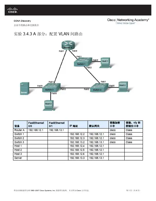
CCNA Discovery企业中的路由和交换简介实验 3.4.3 A 部分:配置 VLAN 间路由设备 FastEthernet0/0 FastEthernet 0/1 IP 地址 默认网关 使能加密 口令使能、vty 和控制台口令 Router A 192.168.12.1 192.168.13.1 cisco ClassSwitch 1 192.168.12.2 192.168.12.1 cisco ClassSwitch 2 192.168.12.3 192.168.12.1 cisco ClassSwitch 3 192.168.13.2 192.168.13.1 ciscoClass Host 1 192.168.12.4 192.168.12.1 Host 2 192.168.12.5 192.168.12.1 Host 3 192.168.12.6 192.168.12.1 Server 192.168.13.3 192.168.13.1目标•配置路由器以实现 VLAN 间通信。
•检验 VLAN 之间的连通性。
背景/准备工作本实验分为两部分:A 部分对每个 VLAN 使用单独的路由器接口来配置 VLAN 间路由。
B 部分使用子接口来配置 VLAN 间路由。
实验的 A 部分和 B 部分都必须完成。
本实验的主要内容是使用 Cisco IOS 命令为 Cisco 1841 路由器或同类路由器执行基本配置。
A 部分显示两个不同的 VLAN 如何通过路由器进行通信,其中每个 VLAN 使用单独的快速以太网接口。
不建议采用这种配置,因为这样的拓扑扩展性不强。
建议采用中继,这种方式需要的路由器和交换机端口更少,具体将在 B 部分说明。
本实验的说明信息同样适用于其它路由器,但命令语法可能会有所差异。
本实验需要以下资源:•三台 Cisco 2960 交换机或其它同类交换机•一台具有 2 个以太网接口的路由器,用以连接交换机•四台基于 Windows 的计算机,其中一台需装有终端仿真程序•至少一根 RJ-45 转 DB-9 连接器控制台电缆,用以配置路由器和交换机•两根直通以太网电缆,用以连接路由器到 Switch 1 和 Switch 3•四根直通以太网电缆,用以连接主机和服务器到交换机•两根交叉以太网电缆,分别用于连接 Switch 1 到 Switch 2 以及连接 Switch 2 到 Switch 3注意:确保已经擦除路由器和所有交换机的启动配置。
Quick Start GuideCisco Small BusinessUnified Communications UC320W with FXO Package Contents•Unified Communications System•Ethernet Network Cable•Phone Cable•Power Adapter•Power Cord Retention Kit•Quick Start Guide•Phone Quick Reference Card•Product CD-ROMC AUTION Be sure to read Section 1 before installation.2Cisco UC320W Quick Start GuideWelcomeThank you for choosing the Cisco Small Business Unified Communications Model UC320W. This guide describes how to install the equipment and get started configuring the system.Before You BeginMinimum Requirements•PC with web browser and Adobe Flash Player version 10.1 or later.•Cisco SPA300 Series or Cisco SPA500 Series IP phones.•Power adapters for the phones, as needed. Cisco SPA300 Seriesphones always require power adapters. Cisco SPA500 Series phones can receive power from a Power over Ethernet switch. •Ethernet cables to connect IP phones and computers.•Internet service.•Voice over IP service or analog phone service.Default SettingsN OTE Be sure to update to the latest firmware when asked at thebeginning of the installation.C AUTION Before installing the Cisco UC320W into an existing networkwith another DHCP server, refer to the Smart Designs (see links onpage 7). Carefully follow the instructions in this guide and in the UC320W Simple Configuration Utility. IP address conflicts will result if two DHCP servers are installed on your network.Parameter Default Value Username cisco Passwordcisco LAN IP(Also the address for the web-based configuration utility.)192.168.10.1DHCP Range (DHCP server is enabled by default.)192.168.10.100 to 149Netmask 255.255.255.0Voice VLAN100Default Voice VLAN Subnet10.1.1.11Optional Equipment and Services•Secure router for Internet access: Cisco recommends using a secure router, such as a Cisco SRP500 Series Services Ready Platform or a Cisco SA500 Series Security Appliance.•Additional ports for IP phones and network devices: Connect a Cisco ESW500 Series Power over Ethernet Switch to a LAN port. Otherswitches may be used but may require configuration of VLAN and QoS settings. Refer to the VLAN information in Default Settings, page2. For application notes, see the documentation links in Where to Go From Here, page7.•Additional ports for analog devices and analog phone lines: Add up to two Cisco SPA8800 IP T elephone Gateways with 4 FXO ports and 4 FXS ports. All added FXS ports count toward the 24 user maximum. A device connected to the Cisco UC320W built-in FXS port (shownbelow) is not counted.•ISDN BRI service:Install a Mediatrix™ 4400 Digital Gateway, Connect both the Cisco UC320W and the BRI gateway to a secure router such as Cisco SA500. For application notes, see the documentation links in Where to Go From Here, page7.•Power cord retention kit: T o prevent accidental removal of the power cord, you can install the supplied power cord retention kit (notillustrated). Remove the screw next to the power port. Connect the clamp to the power cord. Insert the screw and install it onto the Cisco UC320W. For detailed instructions, see the Cisco UC320Wadministration guide.N OTE For best results, install the latest firmware for any network devices, such as routers and Ethernet switches, before proceeding.Installing the Equipment and Configuring the 2SystemS TEP1Before you begin, gather the following information:•Account information from your Internet Service Provider•Phone numbers and account information for all phone services•Names and phone settings for your users and groups•Details for telephony features such as internal dialing, call routing, and Auto AttendantS TEP2Connect a network cable from the WAN port of the Cisco UC320W to your Internet Service or Internet access device.Cisco UC320W Quick Start Guide3S TEP3Connect the supplied power cord to the POWER port and to a power outlet.When the device is fully booted, the POWER/SYS light is steadygreen.S TEP4Connect your PC to a LAN port on the Cisco UC320W. Do not connect any devices to the LAN ports at this point. Your PCwill receive an IP address in the 192.168.10.x range.N OTE:•You may need to adjust your PC’s connecting settings to receive an IP address dynamically.•For best results, set the screen resolution to 1024x768 or higher.S TEP5Start a web browser. In the Address bar, enter the IP address of the Cisco UC320W (default 192.168.10.1).S TEP6T o log in, enter the username cisco and the password cisco.Both the username and the password are case sensitive.S TEP7When prompted, enter a new username and password. Neither cisco nor admin is valid.S TEP8Follow the instructions in the configuration utility to connect the equipment and configure the system.Notes:•If you are installing the Cisco UC320W in a network with another DHCP server, be sure to complete the NetworkT opology step in the Getting Started menu.•For best results, enable access to Cloud Services and accept all available firmware updates.4Cisco UC320W Quick Start GuideCisco UC320W Quick Start Guide5Getting to Know the Cisco UC320WInstallation Guidelines•Ensure adequate air flow.•Do not stack or place anything on top of the Cisco UC320W, or install it on a hot surface.•Ensure that the Cisco UC320W is secure and stable.N OTE For mounting options, see the Cisco UC320W administrationguide.Environmental Considerations•Storage T emperature (sea level): -22° F to 140° F (-30° C to +60° C)•Operating T emperature (sea level): 32°F to 104°F (0°C to 40°C)•Relative Humidity (sea level): 5 to 95% RH (non-condensing)Front Panel1POWER/SYS On - Normal operation. Slow flashing - Booting up. Fast flashing - Upgrading firmware. Off - No power.2LAN On - Connected to a device. Flashing - Sending or receiving data. Off - Not connected.3WAN On - Connected to WAN. Flashing - Sending or receiving data. Off - Not connected.4PHONE (FXS)On - Service is available on the port, and the port is not in use. Slow Flashing - Service is available and the attached phone is off hook (in use). Off - The port is disabled.5LINE (FXO) On - PSTN line loop detected. Slow Flashing - FXO port is in use. Off - Not connected.6WLAN On - Wireless radio is on. Flashing - Sending or receiving data. Off - Disabled.7VM On - Voice mail is enabled. Fast Flashing - System is full. Slow flashing - Retrieving or recording voice mail. Off - Disabled.8USB For future use.3195715UC 320W6Cisco UC320W Quick Start GuideBack PanelSide Panel9WPS On - WiFi Protected Setup succeeded. Slow flashing - Setup is in progress. Fast flashing - Setup error. Off - Not in use. T o configure a WiFi connection by using WPS, make sure the wireless device is located near the Cisco UC320W, and then press and hold this button until the WPS light flashes.1LINE (FXO) Connect phone lines for traditional phone service.2PHONE (FXS)Connect an analog phone or fax machine.3WAN Connect to the broadband network access device or to an uplink port on an Ethernet switch that is connected to the Internet.4LAN Connect IP phones and other network devices.5LINE OUT Connect to an external speaker system.6LINE IN Connect to an external music source for Music On Hold service (optional).7POWER Connect to a power source. Use only the provided power adapter. Optionally, you can use the power cord retention clamp to prevent accidental removal of the power cord. See instructions in the Cisco UC320W administration guide.1, 3For future use.2RESET - Using a paperclip or similar object, press this button briefly to restart the unit. Press and hold for 10 seconds to restore the factory default settings.195716Where to Go From Here SupportCisco Small Business Support Community /go/ smallbizsupportCisco Small Business Support andResources/go/smallbizhelp Phone Support Contacts /go/sbscCisco Small Business FirmwareDownloads/go/software Product DocumentationUnified Communications UC320W /go/uc300 Smart Designs /go/partner/smartdesignsSPA300 Series IP Phones /go/300phones SPA500 Series IP Phones /go/spa500phonesSA500 Series Security Appliances /go/sa500ESW500 Ethernet Switches /go/esw500help SPA8800 IP T elephony Gateway /go/gateways Cisco Small BusinessCisco Partner Central for Small Business (Partner Login Required)/web/partners/ sell/smbCisco Small Business Home /smb4Cisco UC320W Quick Start Guide7Americas HeadquartersCisco Systems, Inc.170 West T asman DriveSan Jose, CA 95134-1706USASmall Business Support US: 1-866-606-1866 (T oll Free, 24/7)Small Business Support, Global: /go/sbsc78-19296-01 Rev. B0 Cisco and the Cisco Logo are trademarks of Cisco Systems, Inc. and/or its affiliates in the U.S. and other countries. A listing of Cisco's trademarks can be found at /go/ trademarks. Third party trademarks mentioned are the property of their respective owners. The use of the word partner does not imply a partnership relationship between Cisco and any other company. (1005R)© 2011 Cisco Systems, Inc. All rights reserved.。
CCNA Discovery 企业中的路由和交换简介实验 8.3.6 配置和检验 VTY 限制设备 主机名 FastEthernet 0/0 IP 地址 Serial 0/0/0IP 地址 Serial 0/0/0接口类型 默认网关 使能加密口令使能口令、VTY 口令和控制台 口令Router 1 R1 192.168.15.1/24 192.168.16.1/24DTE class cisco Router 2 R2 192.168.17.1/24 192.168.16.2/24DCE class cisco Switch 1 S1 class cisco Switch 2 S2class cisco Host 1 H1 192.168.15.2/24 192.168.15.1 Host 2 H2 192.168.15.3/24 192.168.15.1 Host 3 H3 192.168.17.2/24 192.168.17.1 Host 4H4192.168.17.3/24192.168.17.1目标•使用 access-class 和 line 命令来控制对路由器的 Telnet 访问。
•测试 ACL,确定其是否获得了预期结果。
背景/准备工作本实验将使用 VTY ACL 来限制对路由器的 Telnet 访问。
可以使用符合拓扑图所示接口要求的任何路由器。
例如,可以使用 800、1600、1700、1800、2500、2600 或 2800 系列路由器或其任意组合。
本实验的说明信息同样适用于 1841 路由器。
其它路由器也可使用;但是命令语法可能会有所差异。
根据路由器的型号,接口可能也不同。
例如,有些路由器上的 Serial 0 可能是 Serial 0/0 或 Serial 0/0/0,而 Ethernet 0 可能是 FastEthernet 0/0。
Cisco Catalyst 2960 交换机出厂时已经过预配置,在将其接入网络之前,只需要为它指定基本安全信息即可。
Americas HeadquartersCisco Systems, Inc.170 West Tasman DriveSan Jose, CA 95134-1706USATel: 408 526-4000800 553-NETS (6387)Fax: 408527-0883Getting Started Guide for theCatalyst Express 520 SwitchesSeptember 2007Customer Order Number: DOC-7818063=Text Part Number: 78-18063-02THE SPECIFICATIONS AND INFORMATION REGARDING THE PRODUCTS IN THIS MANUAL ARE SUBJECT TO CHANGE WITHOUT NOTICE. ALL STATEMENTS, INFORMATION, AND RECOMMENDATIONS IN THIS MANUAL ARE BELIEVED TO BE ACCURATE BUT ARE PRESENTED WITHOUT WARRANTY OF ANY KIND, EXPRESS OR IMPLIED. USERS MUST TAKE FULL RESPONSIBILITY FOR THEIR APPLICATION OF ANY PRODUCTS.THE SOFTWARE LICENSE AND LIMITED WARRANTY FOR THE ACCOMPANYING PRODUCT ARE SET FORTH IN THE INFORMATION PACKET THAT SHIPPED WITH THE PRODUCT AND ARE INCORPORATED HEREIN BY THIS REFERENCE. IF YOU ARE UNABLE TO LOCATE THE SOFTWARE LICENSE OR LIMITED WARRANTY, CONTACT YOUR CISCO REPRESENTATIVE FOR A COPY.The following information is for FCC compliance of Class A devices: This equipment has been tested and found to comply with the limits for a Class A digital device, pursuant to part 15 of the FCC rules. These limits are designed to provide reasonable protection against harmful interference when the equipment is operated in a commercial environment. This equipment generates, uses, and can radiate radio-frequency energy and, if not installed and used in accordance with the instruction manual, may cause harmful interference to radio communications. Operation of this equipment in a residential area is likely to cause harmful interference, in which case users will be required to correct the interference at their own expense.The following information is for FCC compliance of Class B devices: The equipment described in this manual generates and may radiateradio-frequency energy. If it is not installed in accordance with Cisco’s installation instructions, it may cause interference with radio and television reception. This equipment has been tested and found to comply with the limits for a Class B digital device in accordance with the specifications in part 15 of the FCC rules. These specifications are designed to provide reasonable protection against such interference in a residential installation. However, there is no guarantee that interference will not occur in a particular installation.Modifying the equipment without Cisco’s written authorization may result in the equipment no longer complying with FCC requirements for Class A or Class B digital devices. In that event, your right to use the equipment may be limited by FCC regulations, and you may be required to correct any interference to radio or television communications at your own expense.You can determine whether your equipment is causing interference by turning it off. If the interference stops, it was probably caused by the Cisco equipment or one of its peripheral devices. If the equipment causes interference to radio or television reception, try to correct the interference by using one or more of the following measures:• Turn the television or radio antenna until the interference stops.• Move the equipment to one side or the other of the television or radio.• Move the equipment farther away from the television or radio.• Plug the equipment into an outlet that is on a different circuit from the television or radio. (That is, make certain the equipment and the television or radio are on circuits controlled by different circuit breakers or fuses.)Modifications to this product not authorized by Cisco Systems, Inc. could void the FCC approval and negate your authority to operate the product.The Cisco implementation of TCP header compression is an adaptation of a program developed by the University of California, Berkeley (UCB) as part of UCB’s public domain version of the UNIX operating system. All rights reserved. Copyright © 1981, Regents of the University of California.NOTWITHSTANDING ANY OTHER WARRANTY HEREIN, ALL DOCUMENT FILES AND SOFTWARE OF THESE SUPPLIERS ARE PROVIDED “AS IS” WITH ALL FAULTS. CISCO AND THE ABOVE-NAMED SUPPLIERS DISCLAIM ALL WARRANTIES, EXPRESSED OR IMPLIED, INCLUDING, WITHOUT LIMITATION, THOSE OF MERCHANTABILITY, FITNESS FOR A PARTICULAR PURPOSE AND NONINFRINGEMENT OR ARISING FROM A COURSE OF DEALING, USAGE, OR TRADE PRACTICE.IN NO EVENT SHALL CISCO OR ITS SUPPLIERS BE LIABLE FOR ANY INDIRECT, SPECIAL, CONSEQUENTIAL, OR INCIDENTAL DAMAGES, INCLUDING, WITHOUT LIMITATION, LOST PROFITS OR LOSS OR DAMAGE TO DATA ARISING OUT OF THE USE OR INABILITY TO USE THIS MANUAL, EVEN IF CISCO OR ITS SUPPLIERS HAVE BEEN ADVISED OF THE POSSIBILITY OF SUCH DAMAGES.CCVP, the Cisco logo, and the Cisco Square Bridge logo are trademarks of Cisco Systems, Inc.; Changing the Way We Work, Live, Play, and Learn is a service mark of Cisco Systems, Inc.; and Access Registrar, Aironet, BPX, Catalyst, CCDA, CCDP, CCIE, CCIP, CCNA, CCNP, CCSP, Cisco, the Cisco Certified Internetwork Expert logo, Cisco IOS, Cisco Press, Cisco Systems, Cisco Systems Capital, the Cisco Systems logo, Cisco Unity, Enterprise/Solver, EtherChannel, EtherFast, EtherSwitch, Fast Step, Follow Me Browsing, FormShare, GigaDrive, HomeLink, Internet Quotient, IOS, iPhone, IP/TV, iQ Expertise, the iQ logo, iQ Net Readiness Scorecard, iQuick Study, LightStream, Linksys, MeetingPlace, MGX, Networking Academy, Network Registrar, Packet, PIX, ProConnect, ScriptShare, SMARTnet, StackWise, The Fastest Way to Increase Your Internet Quotient, and TransPath are registered trademarks of Cisco Systems, Inc. and/or its affiliates in the United States and certain other countries.All other trademarks mentioned in this document or Website are the property of their respective owners. The use of the word partner does not imply a partnership relationship between Cisco and any other company. (0705R)Any Internet Protocol (IP) addresses used in this document are not intended to be actual addresses. Any examples, command display output, and figures included in the document are shown for illustrative purposes only. Any use of actual IP addresses in illustrative content is unintentional and coincidental.Getting Started Guide for the Catalyst Express520 Switches© 2007 Cisco Systems, Inc. All rights reserved.Getting Started Guide for the Catalyst Express 520 SwitchesQuick TourThe Catalyst Express 520 switches are designed to be•Smart—Each switch port is applied with a specific Cisco-recommendedconfiguration (referred to as a Smartports port role) to optimize the switchconnections and to ensure security, transmission quality, and reliability fortraffic from the switch ports.•Simple—Setup of the switch can be through a connection to an existingnetwork with a Dynamic Host Configuration Protocol (DHCP) server, suchas a Cisco Unified Communications 500 Series, or through the Express Setupfeature of the switch device manager GUI.•Secure—The switch supports three levels of business-optimized networksecurity. Traffic between the switch and the network managementapplications is also encrypted through the Secure Sockets Layer (SSL)protocol.1AC power connector 12RPS connector 23Security slot 4System LEDsBox Contents5Admin button6Admin LED7Uplink ports38Downlink ports49Port LEDs1.The model shown is a Catalyst Express 520-24PC-K9 switch. Yourswitch might look slightly different.2.Not all Catalyst Express 520 models have an RPS connector.3.Depending on the Catalyst Express 520 model, the uplink ports canbe dual-purpose ports or 10/100/1000 ports.4.Depending on the Catalyst Express 520 model, the downlink portscan be 10/100 Power over Ethernet (PoE) ports, 10/100 ports, or10/100/1000 ports.Verify that you have received the items shown here. If any item is missing ordamaged, contact your Cisco representative or reseller for instructions.The model shown is a Catalyst Express 520-24PC-K9 switch. Your switch mightlook slightly different.The Catalyst Express520-8PC-K9 switch does not ship with a rack-mountbracket kit. You can order the kit (part number RCKMNT-19-CMPCT=) fromCisco.Getting Started Guide for the Catalyst Express520 SwitchesBefore Connecting CablesBefore Connecting CablesFor best results in setting up the switch, first follow the procedures in the gettingstarted guide that ships with the Cisco Unified Communications 500 Series, whichis part of the Cisco Smart Business Communications System (Figure1 on page9).If you do not have a Cisco Unified Communications 500 Series, follow theprocedure in the “Set Up the Switch” section on page4.The User Guide for the Catalyst Express 520 Switches provides a completedescription of the switch hardware and software features and completeinstallation and setup procedures. It is available on and on theCD-ROM that ships with the switch.Before you install, configure, or upgrade the switch, review the information in theRelease Notes for the Catalyst Express 520 Switches on .Before you power on or install the switch, review the safety information in theRegulatory Compliance and Safety Information for the Catalyst Express520Switches on and on the CD-ROM that ships with the switch. Thisdocument includes warning translations.Warning To prevent the switch from overheating, do not operate it in an area that exceeds the maximum recommended ambient temperature of 113°F (45°C). Toprevent airflow restriction, allow at least 3 inches (7.6 cm) of clearance aroundthe ventilation openings.Statement 17BWarning This equipment must be grounded. Never defeat the ground conductor or operate the equipment in the absence of a suitably installed ground conductor.Contact the appropriate electrical inspection authority or an electrician if youare uncertain that suitable grounding is available. Statement 1024Getting Started Guide for the Catalyst Express520 SwitchesSet Up the SwitchSet Up the SwitchPrerequisites•You need the hardware and software described in the “HardwareRequirements” section and the “Software Requirements” section in Chapter1of the switch user guide.•You need the Category 5 Ethernet cable that is shipped with the switch.•You should disable any pop-up blockers or proxy settings in your browsersoftware and any wireless clients running on your PC or laptop.Getting Started Guide for the Catalyst Express520 SwitchesGetting Started Guide for the Catalyst Express520 SwitchesSet Up the SwitchGetting Started Guide for the Catalyst Express520 Switches 1 9 1 6 8 6Set Up the SwitchSet Up the SwitchTipWe recommend running a secured session with the switch. See the “Secured Sessions with the Switch” section in Chapter 2 of the switch user guide for information on how to ensure that your management session with the switch is protected from unauthorized access.Step 8You can now manage the switch through the Cisco Configuration Assistant and the device manager.We strongly recommend that you download the Cisco Configuration Assistant from and use it to manage the switch. You can download it from the CD-ROM that ships with the switch or from this site:/go/configassistYou can display the device manager by following these steps:1.Start a web browser on your PC or laptop.2.Enter the switch IP address, username, and password (assigned in Step 5) in the web browser, and press Enter . The device manager page appears.Troubleshooting:If the device manager does not appear, make sure that you entered the correct switch IP address in the browser.If you entered the correct switch IP address in the browser, make sure that the switch and your PC or laptop are in the same network or subnetwork. For example:•If your switch IP address is 172.20.20.85 and your PC or laptop IP address is 172.20.20.84, both devices are in the same network.•If your switch IP address is 172.20.20.85 and your PC or laptop IP address is 10.0.0.2, the devices are in different networks and cannot directly communicate without a router. You must either change the switch IP address or change the PC or laptop IP address.Cisco Smart Business Communications SystemCisco Smart Business Communications SystemThe Catalyst Express 520 switches are the recommended companion switches tothe Cisco Unified Communications 500 Series. These devices are part of theCisco Smart Business Communications System solution (Figure1).The Cisco Smart Business Communications System is a unified communicationssolution for small businesses that provides voice, data, video, security, andwireless capabilities while integrating with existing desktop applications likecalendar, e-mail, and Customer Relationship Management (CRM).Figure1Cisco Smart Business Communications System SolutionObtaining Documentation, Obtaining Support, and Security GuidelinesFor information on obtaining documentation, obtaining support, providingdocumentation feedback, security guidelines, and also recommended aliases andgeneral Cisco documents, see the monthly What’s New in Cisco ProductDocumentation, which also lists all new and revised Cisco technicaldocumentation, at:/en/US/docs/general/whatsnew/whatsnew.htmlObtaining Documentation, Obtaining Support, and Security Guidelines。
思科系统公司思科在全球设有 200 多个办事处。
有关地址、电话号码和传真号码信息, 可查阅思科网站:/go/offices思科高级网络安全报告 5.0 安装、设置和用户指南版本 5.02016 年 8 月 12 日本手册中有关产品的规格和信息如有更改,恕不另行通知。
本手册中的所有声明、信息和建议均准确可靠,但我们不为其提供任何明示或暗示的担保。
用户必须承担使用产品的全部责任。
随附产品的软件许可和有限担保在随产品一起提供的信息包中提供,且构成本文的一部分。
如果您无法找到软件许可或有限担保,请与思科代表联系以获取副本。
思科所采用的 TCP 报头压缩是加州大学伯克莱分校 (UCB) 开发的一个程序的改版,是 UCB 的 UNIX 操作系统公共域版本的一部分。
版权所有。
版权所有 © 1981,加州大学董事会。
无论在该手册中是否作出了其他担保,来自这些供应商的所有文档文件和软件都按“原样”提供且仍有可能存在缺陷。
思科和上述供应商不承诺所有明示或暗示的担保,包括(但不限于)对特定用途的适销性、适用性、非侵权性以及因交易、使用或商业惯例所衍生的担保。
在任何情况下,对于任何间接、特殊、连带发生或偶发的损坏,包括(但不限于)因使用或无法使用本手册而导致的任何利润损失或数据损失或损坏,思科及其供应商概不负责,即使思科及其供应商已获知此类损坏的可能性也不例外。
思科和思科徽标是思科和/或其附属公司在美国和其他国家/地区的商标或注册商标。
要查看思科商标列表,请访问此 URL:/go/trademarks。
文中提及的第三方商标为其相应所有者的财产。
“合作伙伴”一词的使用并不意味着思科和任何其他公司之间存在合作伙伴关系。
(1110R)本文档中使用的任何互联网协议 (IP) 地址和电话号码并非实际地址和电话号码。
本文档中所含的任何示例、命令显示输出、网络拓扑图和其他图形仅供说明之用。
说明性内容中用到的任何真实 IP 地址或电话号码纯属巧合,并非有意使用。