Monitoring current–voltage characteristics and energy output of silicon photovoltaic modules.
- 格式:pdf
- 大小:283.58 KB
- 文档页数:13
600mA Standalone LinearLi-Ion Battery Charger withThermal Regulation in ThinSOTGeneral DescriptionThe LP4054 is a complete constant-current/constant- voltage linear charger for single cell lithium-ion batteries. Its ThinSOT package and low external component count make the LP4054 ideally suited for portable applications. Furthermore, the LP4054 is specifically designed to work within USB power specifications.No external sense resistor is needed, and no blocking diode is required due to the internal MOSFET architecture. Thermal feedback regulates the charge current to limit the die temperature during high power operation or high ambient temperature. The charge voltage is fixed at 4.2V, and the charge current can be programmed externally with a single resistor. The LP4054 automatically terminates the charge cycle when the charge current drops to 1/10th the programmed value after the final float voltage is reached. When the input supply (wall adapter or USB supply) is removed, the LP4054 automatically enters a low current state, dropping the battery drain current to less than 2µA. The LP4054 can be put into shutdown mode, reducing he supply current to 25µA.Other features include charge current monitor, undervoltage lockout, automatic recharge and a status pin to indicate charge termination and the presence of an input voltage.Ordering InformationLP4054 □□□PackageB5:SOT23-5 FeaturesProgrammable Charge Current Up to 800mANo MOSFET, Sense Resistor or Blocking Diode RequiredComplete Linear Charger in ThinSOT Package forSingle Cell Lithium-ion BatteriesConstant-Current/Constant-Voltage Operation with Thermal Regulation to Maximize ChargeRate Without Risk of OverheatingCharges Single Cell Li-Ion Batteries Directly from USB PortPreset 4.2V Charge Voltage with ± 1% Accuracy Charge Current Monitor Output for Gas GaugingAutomatic RechargeSoft-Start Limits Inrush CurrentAvailable in 5-Lead SOT-23 Package2.9V Trickle Charge ThresholdC/10 Charge Termination25mA Supply Current in Shutdown2.9V Trickle Charge ThresholdApplicationsPortable Media Players/MP3 playersCellular and Smart mobile phoneCharging Docks and CradlesBluetooth ApplicationsMarking InformationPlease see website.F:PB-FreeLP4054LP4054LP4054LP4054LP4054PINLP4054DESCRIPTIONCHRG 1 Open-Drain Status OutputGND 2Ground BAT 3 Charge Current Output VCC4Positive Input Supply VoltagePROG 5Charge Current Program, Charge Current Monitor andShutdown Pin.Pin FunctionsCHRG (PIN 1):Open-Drain Charge Status Output. When the battery is charging, the CHRG pin is pulled low by an internal N-channel MOSFET. When the charge cycle is completed, a weak pull-down of approximately 12µA is connected to the CHRG pin, indicating a “AC present” condition. When the LP4054 detects an undervoltage lockout condition, CHRG is forced high impedance.GND (PIN 2): Ground. BAT (PIN 3):Charge Current Output. Provides charge current to the battery and regulates the final float voltage to 4.2V. An internal precision resistor divider from this pin sets the float voltage which is disconnected in shutdown mode. VCC (PIN 4): Positive Input Supply Voltage. Provides power to the charger. V CC can range from 4.35V to 6.5V and should be bypassed with at least a 1µF capacitor. When V CC drops to within 30mV of the BAT pin voltage, the LP4054 enters shutdown mode, dropping IBAT to less than 2µA.PROG (PIN 5): Charge Current Program, Charge Current Monitor and Shutdown Pin. The charge current is programmed by connecting a 1% resistor, R PROG , to ground. When charging in constant-current mode, this pin servos to 1V. In all modes, the voltage on this pin can be used to measure the charge current using the following formula:The PROG pin can also be used to shutdown the charger. Disconnecting the program resistor from ground allows a 3µA current to pull the PROG pin high. When it reaches the 1.94V shutdown threshold voltage, the charger enters shutdown mode, charging stops and the input supply current drops to 25µA. This pin is also clamped to approximately 2.4V. Driving this pin to voltages beyond the clamp voltage will draw currents as high as1.5mA. Reconnecting R PROG to ground will return the charger to normal operation.LP4054 (TSOT23-5)Absolute Maximum Ratings(Over 0C ≤TJ ≤125°C and recommended supply voltage)Note 1: Absolute Maximum Ratings are those values beyond which the life of the device may be impaired.Note 2: The LP4054 are guaranteed to meet performance specifications from 0℃ to 70℃. Specifications over the -40℃ to 85℃ operating temperature range are assured by design, characterization and correlation with statistical process controls.Note 3: See Thermal Considerations.Note 4: Supply current includes PROG pin current (approximately 100µA) but does not include any current delivered to the battery through the BAT pin (approximately 100mA).Note 5: This parameter is not applicable to the LP4054X.Note 6: I TERM is expressed as a fraction of measured full charge current with indicated PROG resistor.OperationThe LP4054 is a single cell lithium-ion battery charger using a constant-current/constant-voltage algorithm. It can deliver up to 800mA of charge current (using a good thermal PCB layout) with a final float voltage accuracy of ± 1%. The LP4054 includes an internal P-channel power MOSFET and thermal regulation circuitry. No blocking diode or external current sense resistor is required; thus, the basic charger circuit requires only two external components. Furthermore, the LP4054 is capable of operating from a USB power source.Normal Charge CycleA charge cycle begins when the voltage at the V CC pin rises above the UVLO threshold level and a 1% program resistor is connected from the PROG pin to ground or when a battery is connected to the charger output. If the BAT pin is less than 2.9V, the charger enters trickle charge mode. In this mode, the LP4054 supplies approximately 1/10 the programmed charge current to bring the battery voltage up to a safe level for full current charging. (Note: The LP4054X does not include this trickle charge feature).When the BAT pin voltage rises above 2.9V, the charger enters constant-current mode, where the programmed charge current is supplied to the battery. When the BAT pin approaches the final float voltage (4.2V), the LP4054 enters constant-voltage mode and the charge current begins to decrease. When the charge current drops to 1/10 of the programmed value, the charge cycle ends.Programming Charge CurrentThe charge current is programmed using a single resistor from the PROG pin to ground. The battery charge current is 1000 times the current out of the PROG pin. The program resistor and the charge current are calculated using the following equations:The charge current out of the BAT pin can be determined at any time by monitoring the PROG pin voltage using the following equation:Charge TerminationA charge cycle is terminated when the chargecurrent falls to 1/10th the programmed value after the final float voltage is reached. This condition is detected by using an internal, filtered comparator to monitor the PROG pin. When the PROG pin voltage falls below 100mV for longer than tTERM (typically 1ms), charging is terminated. The charge current is latched off and the LP4054 enters standby mode, where the input supply current drops to 200µA.When charging, transient loads on the BAT pin can cause the PROG pin to fall below 100mV for short periods of time before the DC charge current has dropped to 1/10th the programmed value. The 1ms filter time (T TERM ) on the termination comparator ensures that transient loads of this nature do not result in premature charge cycle termination. Once the average charge current drops below 1/10th the programmed value, the LP4054 terminates the charge cycle and ceases to provide any current through the BAT pin. In this state, all loads on the BAT pin must be supplied by the battery.The LP4054 constantly monitors the BAT pin voltage in standby mode. If this voltage drops below the 4.05V recharge threshold (V RECHRG ), another charge cycle begins and current is once again supplied to the battery. To manually restart a charge cycle when in standby mode, the input voltage must be removed and reapplied, or the charger must be shut down and restarted using the PROG pin. Figure 7 shows the state diagram of a typical charge cycle.Charge Status Indicator(CHRG)The charge status output has three different states: strong pull-down(~10mA), weak pull-down (~12µA) and high impedance. The strong pull-down state indicates that the LP4054 is in a charge cycle. Once the charge cycle has terminated , the pin state is determined by undervoltage lockout conditions. A weak pull-down indicates that V CC meets the UVLO conditions and the LP4054 is ready to charge. High impedance indicates that the LP4054 is in undervoltage lockout mode: either V CC is less than 100mV above the BAT pin voltage or insufficient voltage is applied to the V CC pin. A microprocessor can be used to distinguish betweenthese three states –this method is discussed in the Applications Information section.Charge TerminationAn internal thermal feedback loop reduces the programmed charge current if the die temperature attempts to rise above a preset value of approximately 120℃. This feature protects the LP4054 from excessive temperature and allows the user to push the limits of the power handling capability of a given circuit board without risk of damaging the LP4054. The charge current can be set according to typical (not worst-case) ambient temperature with the assurance that the charger will automatically reduce the current in worst-case conditions. ThinSOT power considerations are discussed further in the Applications Information section.Undervoltage Lockout (UVLO)An internal undervoltage lockout circuit monitors the input voltage and keeps the charger in shutdown mode until V CC rises above the undervoltage lockout threshold .The UVLO circuit has a built-in hysteresis of 200mV. Furthermore, to protect against reverse current in the power MOSFET, the UVLO circuit keeps the charger in shutdown mode if V CC falls to within 30mV of the battery voltage. If the UVLO comparator is tripped, the charger will not come out of shutdown mode until V CC rises 100mV above the battery voltage.Manual ShutdownAt any point in the charge cycle, the LP4054 can be put into shutdown mode by removing RPROG thus floating the PROG pin. This reduces the battery drain current to less than 2µA and the supply current to less than 50µA. A new charge cycle can be initiated by reconnecting the program resistor. In manual shutdown, the CHRG pin is in a weakpull-down state as long as VCC is high enough to exceed the UVLO conditions. The CHRG pin is in a high impedance state if the LP4054 is in under voltage lockout mode: either VCC is within 100mV of the BAT pin voltage or insufficient voltage is applied to the VCC pin.Automatic RechargeOnce the charge cycle is terminated, the LP4054 continuously monitors the voltage on the BAT pin using a comparator with a 2ms filter time (T RECHARGE). A charge cycle restarts when the battery voltage falls below 4.05V (which corresponds to approximately 80% to 90% battery capacity). This ensures that the battery is kept at or near a fully charged condition and eliminates the need for periodic charge cycle initiations. CHRG output enters a strong pull-down state during recharge cycles.Application InformationStability ConsiderationsThe constant-voltage mode feedback loop is stable without an output capacitor provided a battery is connected to the charger output. With no battery present, an output capacitor is recommended to reduce ripple voltage. When using high value, low ESR ceramic capacitors, it is recommended to add a 1Ω resistor in series with the capacitor. No series resistor is needed if tantalum capacitors are used. In constant-current mode, the PROG pin is in the feedback loop, not the battery. The constant-current mode stability is affected by the impedance at the PROG pin. With no additional capacitance on the PROG pin, the charger is stable with program resistor values as high as 20k. However,additional capacitance on this node reduces the maximum allowed program resistor. The pole frequency at the PROG pin should be kept above 100kHz. Therefore, if the PROG pin is loaded with a capacitance, PROG, the following equation can be used to calculate the maximum resistance value for RPROG:Average, rather than instantaneous, charge current may be of interest to the user. For example, if a switching power supply operating in low current mode is connected in parallel with the battery, the average current being pulled out of the BAT pin is typically of more interest than the instantaneous current pulses. In such a case, a simple RC filter can be used on the PROG pin to measure the average battery current as shown in Figure 8. A 10k resistor has been added between the PROG pin and the filter capacitor to ensure stability.Power DissipationThe conditions that cause the LP4054 to reduce chargecurrent through thermal feedback can be approximated byconsidering the power dissipated in the IC. Nearly all of thispower dissipation is generated by the internalMOSFET—this is calculated to be approximately:P D =(V CC -V BAT ) • I BATwhere P D is the power dissipated, V CC is the input supply voltage, V BAT is the battery voltage and I BAT is the charge current. The approximate ambient temperature at which the thermal feedback begins to protect the IC is:T A =120℃-P D θJAT A =120℃-(V CC -V BAT ) • I BAT • θJAExample: An LP4054 operating from a 5V USB supply is programmed to supply 400mA full-scale current to a discharged Li-Ion battery with a voltage of 3.75V. Assuming θJA is 150℃/W (see Board Layout Considerations ), the ambient temperature at which the LP4054 will begin to reduce the charge current is approximately:T A =120℃-(5V-3.75V) • (400mA) • 150℃/W T A =120℃-0.5W • 150℃/W =120℃-75℃ T A =45℃The LP4054 can be used above 45℃ ambient, but the charge current will be reduced from 400mA. Theapproximate current at a given ambient temperature can be approximated by:Using the previous example with an ambient temperature of 60℃, the charge current will be reducedto approximately:Moreover, when thermal feedback reduces the chargecurrent, the voltage at the PROG pin is also reducedproportionally as discussed in the Operation section. Itis important to remember that LP4054 applications donot need to be designed for worst-case thermalconditions since the IC will automatically reduce powerdissipation when the junction temperature reaches approximately 120℃.Thermal Considerations Because of the small size of the ThinSOTpackage, it is very important to use a good thermal PC board layout to maximize the available charge current. The thermal path for the heat generated by the IC is from the die to the copper lead frame, through the package leads, (especially the ground lead) to the PC board copper. The PC board copper is the heat sink. The footprint copper pads should be as wide asFigure 8. Isolating Capacitive Load on PROG Pin and Filteringpossible and expand out to larger copper areas tospread and dissipate the heat to the surroundingambient. Feedthrough vias to inner or backside copperlayers are also useful in improving the overall thermalperformance of the charger .Other heat sources on theboard, not related to the charger , must also beconsidered when designing a PC board layout becausethey will affect overall temperature rise and themaximum charge current.Increasing Thermal Regulation CurrentReducing the voltage drop across the internal MOSFETcan significantly decrease the power dissipation in theIC. This has the effect of increasing the currentdelivered to the battery during thermal regulation.One method is by dissipating some of the powerthrough an external component, such as aresistor or diode.Example: An LP4054 operating from a 5V wall adapteris programmed to supply 800mA full-scale current to adischarged Li-Ion battery with a voltage of 3.75V.Assuming θJA is 125℃/W, the approximate chargecurrent at an ambient temperature of 25℃ is:By dropping voltage across a resistor in series with a 5Vwall adapter (shown in Figure 9), the on-chip powerdissipation can be decreased, thus increasing thethermally regulated charge current.:Solving for I BAT using the quadratic formaula2Using R CC = 0.25Ω, V S = 5V, V BAT = 3.75V, T A = 25℃and θJA = 125℃/W we can calculate the thermallyregulated charge current to be:While this application delivers more energy to thebattery and reduces charge time in thermal mode, itmay actually lengthen charge time in voltage mode ifVCC becomes low enough to put the LP4054 intodropout.This technique works best when RCC values areminimized to keep component size small and avoiddropout. Remember to choose a resistor with adequatepower handling capability.VCC Bypass CapacitorMany types of capacitors can be used for inputbypassing, however, caution must be exercised whenusing multilayer ceramic capacitors. Because of theself-resonant and high Q characteristics of some typesof ceramic capacitors, high voltage transients can begenerated under some start-up conditions, such asconnecting the charger input to a live powersource .Adding a 1.5Ω resistor in series with an X5Rceramic capacitor will minimize start-up voltageCharge Current Soft-StartThe LP4054 includes a soft-start circuit to minimize theinrush current at the start of a charge cycle. When acharge cycle is initiated, the charge current ramps fromzero to the full-scale current over a period of approximately 100µs. This has the effect of minimizingthe transient current load on the power supply duringstart-up.CHRG Status Output PinThe CHRG pin can provide an indication that the input voltage is greater than the undervoltage lockout threshold level. A weak pull-down current of approximately 12µA indicates that sufficient voltage isapplied to VCC to begin charging. When a dischargedbattery is connected to the charger, the constant currentportion of the charge cycle begins and the CHRG pin pulls to ground. The CHRG pin can sink up to 10mA to drive an LED that indicates that a charge cycle is in progress. When the battery is nearing full charge, the charger enters the constant-voltage portion of the charge cycle and the charge current begins to drop. When the charge current drops below 1/10 of the programmed current, the charge cycle ends and the strong pull-down is replaced by the 12µA pull-down, indicating that the charge cycle has ended. If the input voltage is removed or drops below the under voltagelockout threshold, the CHRG pin becomes high impedance. Figure 10 shows that by using two different value pull-up resistors, amicro-processor can detect all three states from this pin.To detect when the LP4054 is in charge mode, force the digital output pin (OUT) high and measure the voltage at the CHRG pin. The N-channel MOSFET will pull thepin voltage low even with the 2k pull-up resistor. Once the charge cycle terminates, the N-channel MOSFET is turned off and a 12µA current source is connected to the CHRG pin. The IN pin will then be pulled high by the 2k pull-up resistor. To determine if there is a weak pull-down current, the OUT pin should be forced to ahigh impedance state. The weak current source will pull the IN pin low through the 800k resistor; if CHRG is high impedance, the IN pin will be pulled high, indicating that the part is in a UVLO state. Reverse Polarity Input Voltage ProtectionIn some applications, protection from reverse polarity voltage on VCC is desired .If the supply voltage is highenough, a series blocking diode can be used. In other cases, where the voltage drop must be kept low a P-channel MOSFET can be used (as shown in Fig 11.) USB and Wall Adapter Power The LP4054 allows charging from both a wall adapter and a USB port. Figure 12 shows an example of how to combine wall adapter and USB power inputs. AP-channel MOSFET, MP1,is used to prevent back conducting into the USB port when a wall adapter is present and a Schottky diode, D1, is used to preventUSB power loss through the 1k pull-down resistor. Typically a wall adapter can supply more current thanthe 500mA-limited USB port. Therefore, an N-channel MOSFET, MN1, and extra 10k program resistor are used to increase the charge current to 600mA when the wall adapter is present.Packaging Information。
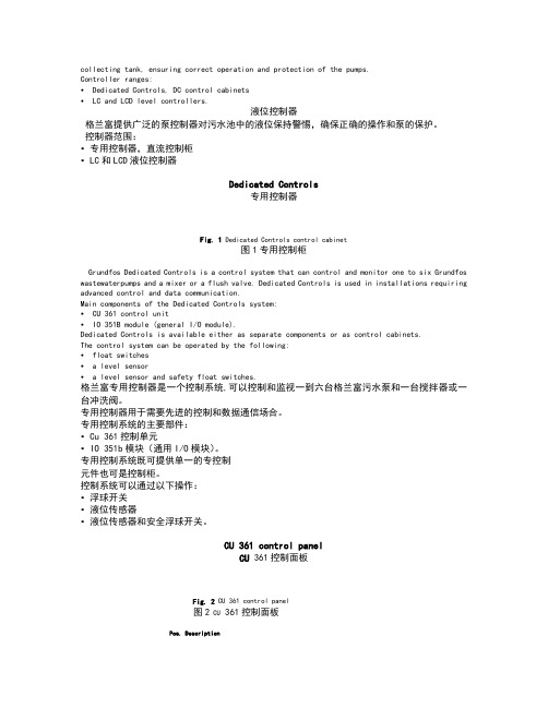
collecting tank, ensuring correct operation and protection of the pumps.Controller ranges:• Dedicated Controls, DC control cabinets• LC and LCD level controllers.液位控制器格兰富提供广泛的泵控制器对污水池中的液位保持警惕,确保正确的操作和泵的保护。
控制器范围:•专用控制器,直流控制柜•LC和LCD液位控制器Dedicated Controls专用控制器Fig. 1 Dedicated Controls control cabinet图1专用控制柜Grundfos Dedicated Controls is a control system that can control and monitor one to six Grundfos wastewaterpumps and a mixer or a flush valve. Dedicated Controls is used in installations requiring advanced control and data communication.Main components of the Dedicated Controls system:• CU 361 control unit• IO 351B module (general I/O module).Dedicated Controls is available either as separate components or as control cabinets.The control system can be operated by the following:• float switches• a level sensor• a level sensor and safety float switches.格兰富专用控制器是一个控制系统,可以控制和监视一到六台格兰富污水泵和一台搅拌器或一台冲洗阀。
Intelligent circuit breaker forecastingand rewarding system researchAbstractThis paper describes an intelligent circuit breaker software and hardware design, real-time multi-task alarm system will be introduced into circuit breaker monitoring and control, to the timely opening and timely alarm. According to the different impact parameters, the different alarm information was given, increasing the protection and alerts function of the circuit.1 IntroductionIn recent years, the IEEE Sub-committee of power system reliability had made an investigation on the reliability of low-voltage circuit breakers, the investigation report only pointed out that the main failure mode of circuit breaker is debugging inaccurate of short-circuit protection, but not proposing the solutions. And the reliability of circuit breaker operation is very prominent. In 1986, the IEEE switching equipment technical committee had set up a new reliability working group of circuit breaker, which pointed out that operation failure (mechanical failure) was the main reason for a circuit breaker failure. Thus increasing prediction design is very necessary in the circuit breaker virtual designed.The using number of circuit breakers increasing year by year, the market capacity of online monitoring products is also expanding. Although such equipment in the installation, commissioning, equipment reliability and so on, there are still many problems, but these problems can be improved and solved through technology. According to market research analysis, the prices of domestic on-line monitoring products are in the following 200,000. In 2002, statistical data shows that the potential market capacity of currently on-line monitoring is 500 million Yuan, the actual market capacity only 0.10 million. In these circumstances, the on-line monitoring market capacities of the circuit breaker are relatively larger in the current development.China's industrial Ethernet overall level is not high, low-voltage distribution industries need to do a lot of research and development work in intelligence and network, in order to raise the intelligent level of domestic low-voltage electrical, to learn the world's most advanced industrial Ethernet technology, and solve the real problem. In order to improve reliability, the warning systems of circuit breaker are proposed, before the electrical equipment failures, predicting to users. The subject are completed equipment research and development by using embedded systems, followed MODBUS / TCP industrial Ethernet protocol, and the basic function is areal-time scanning and alarm, error-correcting functions, and hung activated, self-diagnosis, e.g. Additional functions: to realize protocol conversion between Ethernet network and industrial on-line bus.2 Forecasting and Early Warning System2.1 System Architecture DesignAlthough the circuit breaker itself cost than the cost of other equipment is much lower, such as generators, transformers, but the event of an accident, resulting the loss is much larger than the circuit breaker itself value, so the reliability of their work must be take notice.On the current development state, the majority of domestic substation electrical equipment still accorded to the requiring of electrical equipment preventive test order, periodically going on preventive tests. The test project and cycle of circuit breakers oil and SF6 gas were strict requirement, more test projects, the need for a relatively long period of stop power, affecting the users normal electricity; Moreover, the preventive tests that imposed on the test voltage are relatively low, and the difference between the actual operation is large, and difficult to reflect the real operation process of circuit breaker.Accordance with circuit breaker need to provide electrical power system protection, prediction and real-time multi-tasking system are put forward, the system can analysis, monitoring and alarm to the operation of the circuit breaker. System architecture is seen as Fig.1.2.2 Real-time multi-tasking operating systemμC/OS- is a small core of embedded real-time operating system, the entire code can be divided into core layer and transplantation layer, thus easier to transplant. It uses Preemptive scheduling strategy to ensure the real-time task; be able to manage up to 64 tasks; provide mail, message queues, semaphores, memory management, time management, and other system services. At the same time, it is an open-source generation code, which makes the system upgrades and future maintenance are very convenient. μC/OS - core using standard C language code to prepare, the code can be easy to transplant to a variety of microprocessor.After the operating system ported to the device, in combination with the device achieved functions, the above functions will be distributed to the four works to achieve, namely to protect mission, communications tasks, mission control and display tasks. The applications procedure establish various tasks in the operating system, allocating each task different priority level, the operating system dynamic schedule tasks according to the priority and achieve all the functionality of devices. For all tasks, in a moment, there is only one running task. Tasks of the four kinds of state converse based on certain conditions. The state conversion is seen as Fig.2.In the system, the various functions can be divided into different priority task, through real-time operating system to achieve the regulation management of all tasks, in the single task, solving difficult to deal with and real-time poor problems, that also can enhance system reliability.3 System hardware and software designIn electrical intelligent: real-time performance is the key point, using the high-speed 32-bit ARM 7 TDMI microprocessor as the CPU system, the larger expansion of FLASH program storage space, the high-speed SDRAM as running space, while embedded source code open μCDOS-II unified management application process, and allocation tasks priority, so that high-speed data communication network have no congestion.3.1 Condition monitoring and alarmCondition monitoring refers to understand and master the operational status of equipment, including the use of test, measurement, monitoring, analysis and discrimination, with the system's history and current situation, and consideration environmental factors that assess the operation state of switching equipment, judgments its in normal or non-normal conditions, and displaying and recording the status, alarming the unusual circumstances, which operating personnel can be dealt with promptly, and switching equipment failure analysis, performance assessment, the reasonably using of provision information and preparing basis data.Switching equipment state usually can be divided into hardware fault and software fault. Software fault is that the software itself may be problem, but also may be caused by improper operation or may be caused by system mistakes. Hardware failures are caused by the circuit breaker itself. According to the switching equipment the severity of the fault condition, hardware failures are divided into the minor hardware failure and serious hardware failures. The slight hardware failures are the general fault that the circuit breaker state signal will definitely be changes and equipment performance has been deterioration, but can still barely able to maintain operation. Serious hardware failures are the unexpected emergencies that circuit breakers can not run down; leading to the devastating disaster fault, as well as the moment breakdown for some reason.Its basic principle is the circuit breaker in functioning condition, using all kinds of the measurement tool to monitor its working current, voltage, and other parameters. Adoption sensors will be measured signals, extracted electric and non-electric signals, and converted into the standard form signals that measuring devices can detect signal, inputting digital signal acquisition devices, through the A / D converter, then the corresponding data analysis and feature extraction can be executed.According to the detection the fault state of system, diagnosing circuit breaker what should be done. When the monitoring is the software failure, the software changes. When the monitoring is a slight hardware failure, according to the need, circuit breakers can be continued to use, or opening the standby circuit. When the monitoring is a serious hardware failure, which directly open the standby circuit breaker and repair or replacement the circuit. According to the monitoring hardware failure type, the different alarm measure can be used, the indicator light means light-hardware failure, when a serious hardware failure, the ringing form can be used. Hardware failure alarm circuit is seen as Fig.3.When the monitoring that is slight hardware failure, BG2, BG3 works and bright lights. When the monitoring that is a serious hardware failure, BG2, BG3 stops working, BG4 work, alarm and bell.3.2 Self-diagnosis task scheduling algorithmRegular monitoring the circuit breaker, and the need of considering the following major impact parameters.(1) Monitoring circuit breaker current and voltage of open and break.(2) Monitoring the distance and speed of contact characteristic.(3) Monitoring circuit breaker open and break time, temperature index, and arcing time, e.g. this volume indirectly reflects the operation state of the circuit breaker.(4) Monitoring the transformation state of circuit breaker.(5) Monitoring the movement state of circuit breaker, understanding the action situation and the working condition is good.(6) Monitoring Closing bouncing and rebound. That is, monitoring circuit breaker the mechanical vibration situation.According to the different role of the circuit breaker impact parameters, priority order grow from small to large by impact parameters. Minimum priority 1 is the monitoring circuit breaker open and breaks current and voltage, the biggest priority 6 is the monitoring circuit breaker open and breaks time. Priority data is small, the priority is higher. The monitoring parameters priority of Real-time multi-tasking system shown is seen as Tab.1.Because of different priorities, the algorithm time complexity changes from O (nk) to O (kn), k is the number of circuit breakers impact parameter, that is, k is 6. Reducing time complexity shows that introduction priority setting circuit breaker impact parameters is effective.4. ConclusionsIn sum, low-voltage circuit breaker on-line monitoring system assess and diagnosethe running Circuit Breaker, provided targeted maintenance recommendations, preventing accidents occurred, and optimizing operation of circuit breakers, improving their life. From a technical perspective, it is extremely necessary for ensuring the reliability of the power system and the promoting scientific and technological progress of electrical equipment industry that have a significant role, and having a broad application prospects.This research was sponsored by the National Natural Science Foundation of Hebei Province under the Grants No. E2006001037.智能断路器电路的预报和预警系统的研究摘要本文介绍的智能断路器的软件和硬件设计,实时多任务报警系统就会被引入断路器电路的监测和控制,及时开放和及时报警。

Measuring and monitoring relays Single- and three-phase2 2CDC112184B0201Current and voltage monitoring relays Monitoring the parameters of single-phase mainsCurrent monitoringThe ABB current monitoring relays CM-SRS.xx reliably monitor currents which exceed or fall below the selected threshold value. The functions overcurrent or undercurrent monitoring can be preselected. Single- and multifunction devices for monitoring of direct or alternating currents from 3 mA to 15 A are available.Applications of current and voltage monitoring relays in single-phase mainsCurrent window monitoring (I min , I max )The window monitoring relay CM-SFS.2x is the right solution if the application requires the simultaneous monitoring of over- and undercurrents.Voltage monitoringThe ABB voltage monitoring relays CM-ESS.xx are used to monitor direct and alternating voltages within a range of 3 to 600 V. Over- or undervoltage detection can be preselected.Voltage window monitoring (U min , U max )For the simultaneous detection of over- and undervoltages, the window monitoring relay CM-EFS.2 can be used.For the monitoring of currents and voltages in single-phase AC/DC systems, ABB’s CM range contains a wideselection of powerful and compact devices all in only 22.5 mm wide. This meauring range includes current and voltage monitoring relays for over- and undercurrent protection, over- and undervoltage protection and phase loss monitoring – from 3 mA to 15 A and from 3 V to 600 V. Incorporating ABB’s long-term experience the CM range provides highestsafety and reliability for your electric installation.2CDC112184B0201 3Three-phase monitoring relays Monitoring the parameters in three-phase mainsMonitoring for over- and undervoltageAll electric devices can be damaged when operated continuously at voltages over or under their rated values. An overvoltage could potentially cause heating within the device. If the temperature is unduly high, component parts and thus whole devices or installations may fail or may be destroyed. Undervoltages involve the risk that the switching elements reach an undefined state. In this case, parts of the installation still function, but not others. This misoperation can result in damage of the product or installation. In the worst case, wrong voltages may even cause harm to the operating personnel.Applications for three-phase monitoring relays in three-phase mainsPhase unbalance monitoringIf the supply by the three-phase system is unbalanced due to uneven distribution of the load, the motor will convert a part of the energy into reactive power. This energy gets lost unexploited; also the motor is exposed to higher thermal strain. Other thermal protection devices fail to detect continuing unbalances which can lead to damage or destruction of the motor. The CM range three-phase monitoring relays with phase unbalance monitoring can reliably detect this critical situation.Phase failure detectionIn case of a phase loss, undefined states of the installation are likely to occur. E.g. the startup process of motors is disturbed. All three-phase monitoring relays of the ABB CM range detect a phase loss as soon as the voltage of one phase drops below 60 % of its nominal value.Phase sequence monitoringA change of the phase sequence during operation or an incorrect phase sequence that is applied at start-up will cause a three-phase motor to run with reverse rotation. Certain motors when operated in the reverse direction will cause severe damage to connected loads such as pumps, screw compressors and fans. Especially for non-fixed or portable equipment, such as construction machinery, phase sequence detection prior to the start-up process is highly recommended. ABB offers three-phase monitoring relays with selectable phase sequence monitoring. This provides the capability of ignoring phase sequence conditions for applications, such as motors with forward and reverse rotation, where the phase sequence is Only reliable and continuous monitoring of three-phase networks guarantees trouble-free and economic operation of machines and installations. Thus, the three-phase monitoring relays of the CM range monitor the phase voltages, phase sequence, phase unbalance and phase loss.Interrupted neutralUnder normal conditions, individual phase voltages are equal and the load causes the individual phase currents to vary. Systems that have neutral conductors accommodate this variation by a compensating current flow through the neutralconductor. If the neutral conductor breaks, the compensating current can no longer flow. As a result, the voltage is divided asymmetrically on the individual phases. This means that over- and undervoltages are produced in the individual phases and these can damage or even destroy the connected consumers. ABB offers three-phase monitoring relays that monitor the neutral conductor for interrupted neutral. The interruption of the neutral is detected by means of phase balance monitoring. Automatic phase sequence correctionThe new generation of ABB three-phase monitoring relays offers devices with automatic phase sequence correction. If phase sequence monitoring and phase sequence correction are activated, and in conjunction with a reversing contactor combination, it is ensured that for any non-fixed or portable equipment, e.g. construction machinery, the correct phase sequence is applied to the input terminals of the load.Current and voltage monitoring relays for single-phase AC/DC currentsCurrent monitoring relaysVoltage monitoring relaysCharacteristics of current monitoring relays−Monitoring of DC and AC currents (3 mA to 15 A)−TRMS measuring principle−One device includes 3 measuring ranges−Over- and/or undercurrent monitoring configurable 1)−CM-SFS.2 and CM-SRS.M: Latching function configurable−Hysteresis adjustable (3-30 %) or fixed hysteresis (5 %) 1)−Precise adjustment by front-face operating controls−Screw connection technology orEasy Connect Technology available−Housing material for highest fire protection classificationUL 94 V-0−Tool-free mounting on DIN rail as well as demounting−22.5 mm (0.89 in) width− 3 LEDs for status indication1) depending on deviceCharacteristics of voltage monitoring relays−Monitoring of DC and AC voltages (3-600 V)−TRMS measuring principle−One device includes 4 measuring ranges−Over- and/or undervoltage monitoring configurable 1)−CM-ESS.M and CM-EFS.2: Latching function configurable−Hysteresis adjustable (3-30 %) or fixed hysteresis (5 %) 1)−Precise adjustment by front-face operating controls−Screw connection technology orEasy Connect Technology available−Housing material for highest fire protection classificationUL 94 V-0−Tool-free mounting on DIN rail as well as demounting−22.5 mm (0.89 in) width− 3 LEDs for status indication1) depending on deviceApprovals forcurrent and voltage monitoring relaysA UL 508, CAN/CSA C22.2 No.14C GL(pending)D GOSTK CB SchemeE CCCL RMRSSingle-phase voltage and current monitoring relays protect sensitive equipment and control systems against undervoltage (brownout) or undercurrent events or overvoltage or overcurrent events. Different units with adjustable or fixed threshold values (trip points) are available.All devices are available with two different terminal versions. You can choose between the proven screw connection technology (double-chamber cage connection terminals) and the completely tool-free Easy Connect Technology (push-in terminals).Marks forcurrent and voltage monitoring relaysa CEb C-Tick4 2CDC112184B0201Single- / multifunctional monitoring relays for monitoring of three-phase mainsSinglefunctionalMultifunctionalThe reliable and continuous monitoring of three-phase networks guarantees trouble-free and economic operation of machines and installations.The most multifunctional devices in the EPR assortment are the CM-MPS/N monitoring relays for rated voltage levels up to 820 V AC and 400 Hz. Additionally a variety of economic and cost-efficient three-phase monitoring relays are offered in this range with specialized functionality.Most devices are available with two different terminal versions. You can choose between the proven screw connection technology (double-chamber cage connection terminals) and the completely tool-free Easy Connect Technology (push-in terminals).Characteristics−Monitoring of three-phase mains for phase sequence (canbe switched off), phase failure, phase unbalance over- andundervoltage 1)−TRMS measuring principle−Threshold values are adjustable as absolute values 1)−Powered by the measuring circuit−Precise adjustment by front-face operating controls−Screw connection technology orEasy Connect Technology available−Housing material for highest fire protection classificationUL 94 V-0−Tool-free mounting on DIN rail as well as demounting−S-range: 22.5 mm (0.89 in) width−N-range : 45 mm (1.78 in) width− 3 LEDs for status indication1) depending on deviceApprovalsA UL 508, CAN/CSA C22.2 No.14(CM-PVS.81 pending,not for CM-MPN.72)C GL(pending)D GOSTK CB Scheme(pending)E CCC(CM-PVS.81 pending)Marksa CEb C-Tick(CM-PVS.81 pending)2CDC112184B0201 56 2CDC112184B0201TypeRated control supply voltage Connection technologyMeasuring rangesOrder codeCM-SRS.11P24-240 V AC/DCPush-in terminals3-30 mA, 10-100 mA, 0.1-1 A1SVR 740 840 R0200110-130 V AC 1SVR 740 841 R0200220-240 V AC 1SVR 740 841 R1200CM-SRS.11S24-240 V AC/DCScrew terminals3-30 mA, 10-100 mA, 0.1-1 A1SVR 730 840 R0200110-130 V AC 1SVR 730 841 R0200220-240 V AC 1SVR 730 841 R1200CM-SRS.12S24-240 V AC/DCScrew terminals0.3-1.5 A, 1-5 A, 3-15 A1SVR 730 840 R0300110-130 V AC 1SVR 730 841 R0300220-240 V AC 1SVR 730 841 R1300CM-SRS.21S24-240 V AC/DCScrew terminals3-30 mA, 10-100 mA, 0.1-1 A1SVR 730 840 R0400110-130 V AC 1SVR 730 841 R0400220-240 V AC 1SVR 730 841 R1400CM-SRS.21P24-240 V AC/DCPush-in terminals 1SVR 740 840 R0400110-130 V AC 1SVR 740 841 R0400220-240 V AC 1SVR 740 841 R1400CM-SRS.22S 24-240 V AC/DCScrew terminals0.3-1.5 A, 1-5 A, 3-15 A1SVR 730 840 R0500110-130 V AC 1SVR 730 841 R0500220-240 V AC1SVR 730 841 R1500CM-SRS.M1P 24-240 V AC/DC Push-in terminals 3-30 mA, 10-100 mA, 0.1-1 A 1SVR 740 840 R0600CM-SRS.M1S Screw terminals 1SVR 730 840 R0600CM-SRS.M2S 0.3-1.5 A, 1-5 A, 3-15 A 1SVR 730 840 R0700CM-SFS.21P 24-240 V AC/DC Push-in terminals 3-30 mA, 10-100 mA, 0.1-1 A 1SVR 740 760 R0400CM-SFS.21S Screw terminals1SVR 730 760 R0400CM-SFS.22S0.3-1.5 A, 1-5 A, 3-15A1SVR 730 760 R0500CM-ESS.1P24-240 V AC/DCPush-in terminals3-30 V , 6-60 V , 30-300 V , 60-600 V1SVR 740 830 R0300110-130 V AC 1SVR 740 831 R0300220-240 V AC 1SVR 740 831 R1300CM-ESS.1S24-240 V AC/DCScrew terminals3-30 V , 6-60 V , 30-300 V , 60-600 V1SVR 730 830 R0300110-130 V AC 1SVR 730 831 R0300220-240 V AC 1SVR 730 831 R1300CM-ESS.1P24-240 V AC/DCPush-in terminals3-30 V , 6-60 V , 30-300 V , 60-600 V1SVR 740 830 R0300110-130 V AC 1SVR 740 831 R0300220-240 V AC 1SVR 740 831 R1300CM-ESS.1S24-240 V AC/DCScrew type terminals3-30 V , 6-60 V , 30-300 V , 60-600 V1SVR 730 830 R0300110-130 V AC 1SVR 730 831 R0300220-240 V AC 1SVR 730 831 R1300CM-ESS.1P24-240 V AC/DCPush-in terminals3-30 V , 6-60 V , 30-300 V , 60-600 V1SVR 740 830 R0300110-130 V AC 1SVR 740 831 R0300220-240 V AC 1SVR 740 831 R1300CM-ESS.1S 24-240 V AC/DCScrew type terminals3-30 V , 6-60 V , 30-300 V , 60-600 V1SVR 730 830 R0300110-130 V AC 1SVR 730 831 R0300220-240 V AC 1SVR 730 831 R1300CM-ESS.MP 24-240 V AC/DC Push-in terminals 3-30 V , 6-60 V , 30-300 V , 60-600 V 1SVR 740 830 R0500CM-ESS.MS Screw type terminals 1SVR 730 830 R0500CM-ESS.MP 24-240 V AC/DC Push-in terminals 3-30 V , 6-60 V , 30-300 V , 60-600 V 1SVR 740 830 R0500CM-ESS.MS Screw type terminals 1SVR 730 830 R0500CM-EFS.2P 24-240 V AC/DC Push-in terminals 3-30 V , 6-60 V , 30-300 V , 60-600 V 1SVR 740 750 R0400CM-EFS.2S24-240 V AC/DCScrew type terminals3-30 V , 6-60 V , 30-300 V , 60-600 V1SVR 730 750 R0400Current and voltage monitoring relays Ordering dataThree-phase monitoring relays Ordering dataType Rated control supply voltage =measuring voltage Interrupted neutral monitoring ConnectiontechnologyOrder codeCM-MPS.11P 3 x 90-170 V AC yes Push-in terminals1SVR 740 885 R1300CM-MPS.11S yes Screw terminals1SVR 730 885 R1300CM-MPS.21P 3 x 180-280 V AC yes Push-in terminals1SVR 740 885 R3300CM-MPS.21S yes Screw terminals1SVR 730 885 R3300CM-MPS.31P 3 x 160-300 V AC no Push-in terminals1SVR 740 884 R1300CM-MPS.31S no Screw terminals1SVR 730 884 R1300CM-MPS.41P 3 x 300-500 V AC no Push-in terminals1SVR 740 884 R3300CM-MPS.41S no Screw terminals1SVR 730 884 R3300CM-MPS.23P 3 x 180-280 V AC yes Push-in terminals1SVR 740 885 R4300CM-MPS.23S yes Screw terminals1SVR 730 885 R4300CM-MPS.43P 3 x 300-500 V AC no Push-in terminals1SVR 740 884 R4300CM-MPS.43S no Screw terminals1SVR 730 884 R4300CM-MPS.52P 3 x 350-580 V AC no Push-in terminals1SVR 760 487 R8300CM-MPS.52S no Screw terminals1SVR 750 487 R8300CM-MPS.62P 3 x 450-720 V AC no Push-in terminals1SVR 760 488 R8300CM-MPS.62S no Screw terminals1SVR 750 488 R8300CM-MPS.72P 3 x 530-820 V AC no Push-in terminals1SVR 760 489 R8300CM-MPS.72S no Screw terminals1SVR 750 489 R8300CM-PSS.31P 3 x 380 V AC no Push-in terminals1SVR 740 784 R2300CM-PSS.31S no Screw terminals1SVR 730 784 R2300CM-PSS.41P 3 x 400 V AC no Push-in terminals1SVR 740 784 R3300CM-PSS.41S no Screw terminals1SVR 730 784 R3300CM-PVS.31P 3 x 160-300 V AC no Push-in terminals1SVR 740 794 R1300CM-PVS.31S no Screw terminals1SVR 730 794 R1300CM-PVS.41P 3 x 300-500 V AC no Push-in terminals1SVR 740 794 R3300CM-PVS.41S no Screw terminals1SVR 730 794 R3300CM-PVS.81P 3 x 200-400 V AC no Push-in terminals1SVR 740 794 R2300CM-PVS.81S no Screw terminals1SVR 730 794 R2300CM-PAS.31P 3 x 160-300 V AC no Push-in terminals1SVR 740 774 R1300CM-PAS.31S no Screw terminals1SVR 730 774 R1300CM-PAS.41P 3 x 300-500 V AC no Push-in terminals1SVR 740 774 R3300CM-PAS.41S no Screw terminals1SVR 730 774 R3300CM-PBE 3 x 380-440 V AC, 220-240 V AC yes Screw terminals1SVR 550 881 R9400CM-PBE 3 x 380-440 V AC no Screw terminals1SVR 550 882 R9500CM-PVE 3 x 320-460 V AC, 185-265 V AC yes Screw terminals1SVR 550 870 R9400CM-PVE 3 x 320-460 V AC no Screw terminals1SVR 550 871 R9500CM-PFS 3 x 200-500 V AC no Screw terminals1SVR 430 824 R93002CDC112184B0201 7D o c u m e n t n u m b e r 2C D C 112 184 B 0201 p r i n t e d i n G e r m a n y (04/12-Z V D )Contact usABB STOTZ-KONTAKT GmbH /lowvoltage-> Control Products -> Electronic Relays and Controls -> Three Phase Monitors -> Single Phase Monitors/contactsNote:We reserve the right to make technical changes or modify the contents of this document without prior notice. With regard to purchase orders, the agreed particulars shall prevail. ABB AG does not accept any responsibility whatsoever for potential errors or possible lack of information in this docu-ment.We reserve all rights to this document and the sub-ject matter and illustrations contained therein. Any reproduction, disclosure to third parties or utilisation of its contents – in whole or in part – is forbidden without prior written consent from ABB AG. Copyright© 2012 ABB All rights reserved。

Transformer protection and control RET615Relion ®615 seriesCompact and versatile solution for utility and industrial power distribution systemsRET615 is a dedicated transformer protection and control IED for power transformers, unit and step-up transformers including power generator-transformer blocks in utility and industry power distribution systems.RET615 is a member of ABB’s Relion® protection and control product family and its 615 series. The 615series IEDs are characterized by their compactness and withdrawable-unit design. Re-engineered from the ground up, the 615 series has been designed to unleash the full potential of the IEC 61850 standard for communication and interoperability between substation automation devices.ApplicationRET615 is an advanced protection and control IED for two-winding power transformers and power generator-transformer blocks. RET615 is available in eight standard configurationsto match the most commonly employed power transformer vector groups and to coordinate the applied transformer neutral earthing principles with the relevant earth-fault protection schemes.Protection and controlRET615 features, three-phase, multi-slope stabilized (biased) stage transformer differential protection and an instantaneous stage to provide fast and selective phase-to-phase short-circuit, winding interturn fault and bushing flash-over protection. Besides second harmonic restraint an advanced waveform-based blocking algorithm ensures stability at transformer energization and a fifth harmonic restraint function ensures good protection stability at moderate overexcitation of a power transformer. Sensitive restricted earth-fault protection (REF) completes the overall differential protection providing detection of even single phase-to-earth faults close to the earthed neutral point of the transformer. Either the conventional high-impedance scheme or a numerical low-impedance scheme can be selected for protection of the transformer windings. When low-impedance REF protectionis used, neither stabilizing resistors nor varistors are needed. As a further benefit the transforming ratio of the neutral earthing CT may differ from that of the phase current transformers. Due to its unit protection character and absolute selectivity the REF protection does not need to be time graded with other protection schemes, and therefore high-speed fault clearance can be achieved.RET615 also incorporates a thermal overload protection function, which supervises the thermal stress of the transformer windings to prevent premature aging of the insulation of the windings. Multiple stages of short-circuit, phase-overcurrent, negative-phase-sequence and earth-fault back-up protection are provided for both the high voltage and the low voltage side of the transformer. Depending on the standard configuration the IED also includes three-phase overvoltage protection, three-phase undervoltage protection and earth fault protection based on a measured or calculated residual voltage. Furthermore, RET615 also offers circuit-breaker failure protection. Enhanced with an optional communication card, RET615 offers a fast three-channel arc-fault protection system for arc flash supervision of the circuit-breaker, busbar and cable compartment of metal-enclosed air-insulated switchgears.The optional RTD/mA module offered for the standard configurations A – D allow up to six temperature signals tobe measured via the RTD inputs and two transducer derived analog signals via the mA inputs. The RTD and mA inputs can be used for measuring the oil temperature at the bottom and top of the transformer. Furthermore, the RTD/mA inputs can be used for measuring the ambient air temperature. The RTD inputs also offer thermal protection of dry-type power transformers fitted with Pt-100 temperature sensors. Temperature measurement over the RTD /mA inputs extends the function of the three-phase thermal overload protectionof the IED. An RTD input can also be used as a direct resistance measuring input for position tracking of an on-load tap changer. Alternatively, tap changer position can be obtained via a mA-transducer. The analog temperature or tap changer position values can, if required, be sent using analog horizontal GOOSE messaging to other IEDs.RET615 also integrates functionality for the control of theHV-side circuit breaker via the front panel HMI or by meansof remote controls. RET615 also features two control blocks which are intended for motor-operated control of disconnectors or circuit-breaker trucks and their position indications. Further, RET615 offers a control block which is intended for motor-operated control of one earthing switch control and it’s position indication. The number of controllable primary devices depends on the number of available inputs and outputs in the selected configuration.The signal configuration of the IED can be adjusted using the signal matrix functionality (SMT) or the graphical application configuration functionality (ACT) of the Protection and Control IED Manager PCM600. The ACT supports creation of multi-layer logic by combining various logic functions blocks also including timers and flip-flops. By combining protection functions with logic functions the IED configuration can be modified to fit the special requirements of the application.2 Transformer protection and control | RET615RET615 | Transformer protection and control 3I 2>463I >51P-1 ARC50L3I >>>50P/51PIo > BF51NBFARC 50NL3I >>>50P/51PMAPMAP3I >51P-13I >>51P-2Io3I >>51P-23θ>T49TI 2>463I >BF51BF3I >T87TIo >51N-1Io1) Optional1)1)1)IoLo >87NLIo >>51N-2Protection function overview of the A configuration of RET615.Standardized communicationRET615 features genuine support for the new IEC 61850 standard for inter-device communication in substations. It also supports the DNP3 and the IEC 60870-5-103protocol, as also the industry standard Modbus ® protocol. For a self-healing Ethernet solution the IED offers an optional fibre-optic communication module providing two optical and one galvanic Ethernet network interfaces. Alternatively, the IED features an optional galvanic communication module with two galvanic and one optical Ethernet network interfaces or three galvanic interfaces. The third Ethernet interface provides connectivity of any other Ethernet devices to an IEC 61850 station bus inside of a switchgear bay. The self-healingEthernet solution constitutes a cost efficient communication loop controlled by a managed switch. The managed switch controls the consistency of the loop, routes the data and corrects the flow of data in communication disturbance situations. The self-healing Ethernet ring can be built on the Ethernet based IEC 61850, Modbus ® and DNP3 protocols.The implementation of the IEC 61850 substationcommunication standard in RET615 covers both vertical and horizontal communication, including GOOSE messaging with both binary and analog signals and parameter setting according to IEC 61850-8-1. The substation configuration language enables the use of engineeringtools for efficient configuration and commissioning of substation devices. For accurate time stamping RET615 supports synchronization over Ethernet using SNTP or over a separate bus using IRIG-B.Preventive condition monitoringFor continuous control of its operational availabilityRET615 features a comprehensive set of monitoring functions to supervise the IED itself, the CB trip circuit and the circuit breaker. The IED monitors the wear and tear of the circuit breaker, the spring charging time of the CB operatingmechanism and the gas pressure of the breaker chambers. The IED also supervises the breaker travel time and the num-ber of CB operations to provide basic information for schedul-ing CB maintenance to support asset management.Single line diagramThe 615 series IEDs with large graphical display offer customizable visual single line mimic diagrams (SLD) with position indication for the relevant circuit breaker,disconnectors and the earthing switch. Apart from the default single line diagram, the IED may display related measured values, as provided by the chosen standard configuration. The SLD view can also be accessed through the web-browser based user interface. The default SLD can be modified according to user requirements using the graphical display editor of PCM600.Standard configurationsDescriptionThree-phase transformer differential protection for two-winding transformers, numerical restricted earth-fault protectionfor the high-voltage (HV) side, CB control (HV side) and optional RTD/mA inputsThree-phase transformer differential protection for two-winding transformers, numerical restricted earth-fault protectionfor the low-voltage (LV) side, CB control (HV side), optional RTD/mA inputsThree-phase transformer differential protection for two-winding transformers, high-impedance based restricted earth-fault protection for the high-voltage (HV) side, CB control (HV side) and optional RTD/mA inputsThree-phase transformer differential protection for two-winding transformers, high-impedance based restricted earth-fault protection for the low-voltage (LV) side, CB control (HV side) and optional RTD/mA inputsThree-phase transformer differential protection for two-winding transformers, numerical restricted earth-fault protectionfor the high-voltage (HV) side, phase-voltage based protection and measurement functions and CB control (HV side)Three-phase transformer differential protection for two-winding transformers, numerical restricted earth-fault protectionfor the low-voltage (LV) side, phase-voltage based protection and measurement functions and CB control (HV side)Three-phase transformer differential protection for two-winding transformers, high-impedance based restricted earth-fault protection for the high-voltage (HV) side, phase-voltage based protection and measurement functions and CB control (HV side) Three-phase transformer differential protection for two-winding transformers, high-impedance based restricted earth-fault protection for the low-voltage (LV) side, phase-voltage based protection and measurement functions and CB control (HV side)Standard configurationABCDEFGHStandard configurationsSupported functions, codes and symbolsFunctionalityProtectionStabilized and instantaneous differential protection for two-winding transformers Multi-purpose protection9)Master tripHV-side protectionNumerical stabilized low impedance restricted earth-fault protectionHigh impedance based restricted earth-fault protectionThree-phase non-directional overcurrent protection, low stageThree-phase non-directional overcurrent protection, high stageThree-phase non-directional overcurrent protection, instantaneous stageNon-directional earth-fault protection, low stageNon-directional earth-fault protection, high stageNegative-sequence overcurrent protectionResidual overvoltage protection5)Three-phase undervoltage protectionThree-phase overvoltage protectionThree-phase thermal overload protection for power transformers, two time constants Circuit-breaker failure protection2)LV-side protectionNumerical stabilized low impedance restricted earth-fault protectionHigh impedance based restricted earth-fault protectionThree-phase non-directional overcurrent protection, low stageThree-phase non-directional overcurrent protection, high stageThree-phase non-directional overcurrent protection, instantaneous stageNon-directional earth-fault protection, low stageNon-directional earth-fault protection, high stageNegative-sequence overcurrent protectionArc protection4)4 Transformer protection and control | RET615RET615 | Transformer protection and control 5H 1-2--111--122211-16)11113)13)1(3)A 1(6)21-11111)11)1---11--111--1(3)IEC-ANSI 87T MAP 94/86 87NL 87NH 51P-151P-2 50P/51P 51N-1 51N-24659G 275949T51BF/51NBF 87NL 87NH 51P-151P-2 50P/51P 51N-1 51N-2 4650L/50NLF 1-2--111--12221117)-11118)18)1(3)G 1-2-111112)12)122211--111--1(3)E 1-21-11111)11)122211--111--1(3)IEC 606173dI >T MAP Master Trip dIoLo >dIoHi >3I > 3I >> 3I >>> Io > Io >>I2> Uo > 3U < 3U > 3Ith >T 3I >/Io >BF dIoLo >dIoHi >3I > 3I >> 3I >>> Io > Io >> I2> ARCIEC 61850TR2PTDF MAPGAPC TRPPTRC LREFPNDF HREFPDIF PHLPTOC PHHPTOC PHIPTOC EFLPTOC EFHPTOC NSPTOC ROVPTOV PHPTUV PHPTOV T2PTTR CCBRBRF LREFPNDF HREFPDIF PHLPTOC PHHPTOC PHIPTOC EFLPTOC EFHPTOC NSPTOC ARCSARCD 1(6)2--111--1---11-16)11113)13)1(3)C 1(6)2-111112)12)1---11--111--1(3)B 1(6)2--111--1---1117)-11118)18)1(3)1, 2,... = number of included instances / I/Os( ) = optionalStandard configurationsSupported functions, codes and symbolsFunctionalityControlDisconnector controlEarthing switch controlDisconnector position indicationEarthing switch indicationTap changer position indicationCircuit-breaker control (HV-side)Condition MonitoringCircuit-breaker condition monitoringTrip circuit supervisionFuse failure supervisionRuntime counter for machines and devicesMeasurementDisturbance recorderRTD/mA measurementHV-side measurementThree-phase current measurementSequence current measurementResidual current measurementThree-phase voltage measurementResidual voltage measurementSequence voltage measurementThree-phase power, energy measurement, including power factorLV-side measurementThree-phase current measurementResidual current measurementInputs/OutputsAnalog inputsCTVTRTD inputs13)mA inputs13)Binary outputs/inputsBI13)BO13)6 Transformer protection and control | RET615RET615 | Transformer protection and control 7H 21321112111-11-1111117510)-.1210A 21321112-11(1)111----1-7-(6)11) (2)11)8 (14)12)10 (13)12)IEC-ANSI I ↔ O DCC I ↔ O ESC I ↔ O DC I ↔ O ES 84MI ↔ O CB CBCM TCM 60OPTM -X130 (RTD)3I I1, I2, I0In 3U Vn U1, U2, U0P , E 3I(B)In (B)G 21321112111-11-1111117510)--1210F 21321112111-11111111-7510)--1210E 21321112111-11111111-7510)--1210IEC 60617I ↔ O DCC I ↔ O ESC I ↔ O DC I ↔ O ES TPOSM I ↔ O CB CBCM TCS FUSEF OPTS -X130 (RTD)3I I1, I2, I0Io 3U Uo U1, U2, U0P , E 3I(B)Io (B)IEC 61850DCXSWI ESXSWI DCSXSWI ESSXSWI TPOSSLTC CBXCBR SSCBR TCSSCBR SEQRFUF MDSOPT RDRE XRGGIO130CMMXU CSMSQI RESCMMXU VMMXU RESVMMXU VSMSQI PEMMXU CMMXU RESCMMXUD 21321112-11(1)11-----117-(6)11) (2)11)8 (14)12)10 (13)12)C 21321112-11(1)111----1-7-(6)11) (2)11)8 (14)12)10 (13)12)B 21321112-11(1)11-----117-(6)11) (2)11)8 (14)12)10 (13)12)1, 2,... = number of included instances / I/Os( ) = optional1) Io selectable by parameter and the default value is Io measured 2)Io calculated is always used 3)IoB calculated is always used 4)IoB calculated and 3IB are always used 5)Uo selectable by parameter, Uo measured as default 6)IoB measured is always used 7)IoB measured and 3IB are always used 8)IoB selectable by parameter, IoB measured as default 9)Multi-purpose protection is used for, for example, RTD/mA based protection 10)One of the five inputs is reserved for future applications 11)With optional RTD/mA module 12)With optional binary I/O module ()13)The optional I/O module and the optional RTD/mA modules are mutually exlusiveNote that all directional protection functions can also be used in non-directional mode.The instances of a protection function represent the number of identical function blocks available in a standard configuration. By setting the application specific parameters of an instance, a protection function stage can be established.Contact us1M R S 756898 D , 4.0 © C o p y r i g h t 2012 A B B . A l l r i g h t s r e s e r v e d .For more information see RET615 Product Guide or contact us:ABB Oy, Distribution Automation P .O. Box 699FI-65101 VAASA, Finland Phone: +358 10 22 11Fax: +358 10 22 41094ABB Limited, Distribution Automation Maneja, Vadodara – 390013, India Phone: +91 265 260 4386Fax: +91 265 263 8922/substationautomation。

/simocodeSIMOCODE proFlexible, modular, integrated –the way modern motor management should be.SIMOCODE pro offers multifunctional, solid-state full motor protection. The motor management system monitors, protects and controls constant-speed motors and enables the implementa-tion of predictive maintenance. It does not wait for a problem to occur before shutting down the motor, but establishes a level of transparency in advance to avoid shutdowns and improve productivity. SIMOCODE pro delivers detailed operating, service and diagnostic data across the entire process. SIMOCODE is easy to use, requires no advanced engineering, and integrates into virtually any automation system. SIMOCODE pro communicates via PROFIBUS and PROFINET, Modbus RTU, EtherNet/IP and OPC UA.For 30 years, SIMOCODE pro has been controlling and monitoring low-voltage, constant-speed motors all over the world. For plant reliability, SIMOCODE is used to keep motors running. And with its Cloud-based connection, SIMOCODE gives you more transparency and power.With both the SIMOCODE pro GeneralPerformance and SIMOCODE pro HighPerformance device classes, we offerscalable, flexible solutions for industrialcontrols and plant optimization in thecontext of Industry 4.0.3SIMOCODE pro – General Performance:Ideal for the entry levelThe smart and compact motor management system for direct-on-line, reversing, and star-delta (wye-delta) starters or for controlling a motor starter protector or soft starter. The basic system includes a current measuring module and the basic unit for overload or thermistor motor protection, for example. Communication with the automation level takes place via PROFIBUS/PROFINET. Optional additions include an operator panel and an expansion module that allows additional inputs/ outputs, ground-fault detection and temperature measure-ment to be realized. SIMOCODE pro – High Performance:The fully professional solution for every motorThe SIMOCODE pro High Performance motor management system is variable, intelligent and can be adapted individually to suit any requirement. The basic system includes a module for measuring current (and optionally also voltage), as well as a basic unit, and is suitable for removing pump blockages, for example. Communication with the automation level takes place via PROFIBUS or Modbus RTU, via Ethernet with the PROFINET or EtherNet/IP protocols, and also via OPC UA. The optional expansion modules include separate current/voltage measuring modules for dry-running protection, an operator panel with display, a ground-fault module, a temperature module, standard digital modules, fail-safe digital modules and an analog module.SIMOCODE pro – Modern motor management: scalable and modularTwo device series form the core of the multifunctional SIMOCODE pro motor man-agement system: General Performance and High Performance. The devices in both series incorporate all essential motor protection, monitoring and control functions– including data transparency through the Cloud connection. SIMOCODE pro General Performance is your entry into modern motor management and addresses standard motor applications. SIMOCODE pro High Performance features up to five expansion modules, including fail-safe modules, and offers additional measured variables. Findout how you can take advantage of the two SIMOCODE pro device series in all areasof the automation industry.4SIMOCODE pro Safety:Fail-safe expansion modulesVarious modules are available for SIMOCODE pro for theextended protection of personnel, machines and the envi-ronment. These guarantee the safety-related shutdown ofmotors and meet all the requirements of the standards.The advantages:• F unctional switching and fail-safe shutdown withoutmanual wiring or additional effort• S afety function parameters can be flexibly configured• T ransfer of meaningful diagnostic data to thecontrol system• L ogging of errors for detailed evaluation•Fail-safe shutdown via PROFIsafe or locallyHighPerformanceSIMOCODE pro V PN SIMOCODE pro V EIP SIMOCODE pro V PB SIMOCODE pro V MR Current / voltagemeasuring moduleOperator panel with displaymax. 5 / 7 expansionmodulesSafetyExtended control functions(e.g. positioner, pole-changing starter)GeneralPerformance SIMOCODE pro V PN GP SIMOCODE pro SCurrent measuring moduleOperator panel1 expansion moduleBasic control functions(e.g. direct-on-line/reversing start)5Every water utility operator is familiar with the problems of a blocked pump – and the possible consequences: environmental harm, damage due to flooding, and dangers to health as a result of lifting and cleaning pumps. This is compounded by the financial impact of plantdowntimes. SIMOCODE pro monitors the current and active power of the pump motor – and derives the pumpstatus from them. If a defined threshold value is exceeded, SIMOCODE pro autonomously reverses the rotational direction of the pump in order to dislodge deposits on the impeller blades.Say goodbye to blocked pumps with SIMOCODE pro – the modular, compact motor management system that tackles the challenge by automatically reversing the pump. SIMOCODE pro can be retrofitted in existing plants.Remove pump blockages and increase availability.6Reliable monitoring – dry-running protection redesigned.Conventional dry-running monitoring with a sensor Active power-based dry-running protectionReliable dry-running protection is a must in many applications in the chemical industry. SIMOCODE pro reliably prevents the dry running of centrifugal pumps in order to preclude hazardous situations and completely redefines dry-running protection for pumps inSensors on centrifugal pumps in hazardous areas are often prone to high installation and maintenance costs. The solu-tion: Using active power-based dry-running detection, SIMO-CODE pro monitors the active electrical power consumption of the pump motor and thus the status of the pump – with-out the need for additional monitoring devices or sensors to be installed. The new technology ensures reliable explosion protection in accordance with ATEX and IECEx criteria and saves costs and time for commissioning and maintenance.Your benefits through active power-based dry-running protection Earlier fault detection• D irect conclusions concerning the flow rate can be drawnfrom the active power consumption of the pump motor • R eliable prevention of dry running of the pump andtherefore less damage to the pump Cost and time savings• N o maintenance effort due to the elimination ofmechanical wear of the sensors • No additional sensor requiredReduction of hardware• N o need for additional sensors and mechanicalcomponents • Simplified engineering Reliable monitoring of the system• Compliance with ATEX and IECEx criteria• R eliable and automatic pump shutdown in the event ofunacceptable operating conditions7With the OPC UA industrial M2M communication protocol, SIMOCODE pro provides an additional communication interface that is independent of the automation system.The open and supplier-independentcommunication via OPC UA guaran-tees the direct exchange of data withHMI panels or SCADA systems. Motor,process and plant data is thereforeavailable without any losses, wher-ever it is needed: at the device, butalso in the control room for diagnosticpurposes. As part of the digital revo-lution and the efforts to evaluate vastquantities of data even more quickly,all motor data from SIMOCODE procan be transmitted by the most directroute to the Cloud using OPC UA.The data can then be used moreintensively and in a targetedfashion – without the need forany intervention in the motor control.The result: Plant availability andefficiency are increased, because youcan run analyses, improve energyconsumption, or even optimize theentire process. SIMOCODE pro speaks to everyone –including the Cloud.BenefitsThanks to OPC UA, SIMOCODE facilitatessimple and convenient integrationinto Cloud-based solutions, e.g. SiemensMindSphere with so many advantages:• D ata provision in the Cloud for cross-plant,reliable diagnostics• C onvenient and reliable processoptimization• P lant-wide access to control data,process values and readings withoutcomplex engineering effort• P redictive maintenance, energy datamanagement and resource optimization• E ffective protection against manipulation(security)Digitalization for more economicaloperation: SIMOCODE pro withOPC UA8SIMOCODE ES Software:For diagnostics and simple configu-ration, including in the TIA Portal SIMOCODE ES provides you with the software for the configuration, startup, operation and diagnosis of SIMOCODE pro. The software isbased on the central Totally Integrated Automation Portal (TIA Portal) engi- neering framework, providing an integrated, efficient and intuitive solution for all automation tasks. SIMOCODE ES offers you a host of advantages, including convenient configuration in the device view, graphical commissioning using drag and drop functions, online access to signal states and clear measurementcurves for diagnostic purposes.BenefitsSIMOCODE pro is your reliable data supplier for maximum process quality. The motor management system offers:• Transparency into your process • Data analysis and simulation• S ecure data storage and transmission • Visualization and recommendation(s)• I ncreased availability of components • Optimization of energy consumption • Maximization of process efficiencyThe convenient way to optimumprocess guidance: The integration of SIMOCODE pro into SIMATIC PCS 7Using standardized blocks and face-plates, SIMOCODE pro can very easily be integrated into the SIMATIC PCS 7 process control system. This makes it extremely easy to integrate service and diagnostic data from the motor manage-ment system into higher-level process control systems, for example.The result: A high level of transparency throughout the plant, enabling faults to be detected at an early stage or pre- vented from occurring altogether. In general, the greater density of informa-tion in the control system enables you to achieve not only greater transparency, but also higher process quality.9SIMOCODE pro system overview – high performanceSiemens Industry, Inc. 5300 Triangle Parkway Norcross, GA 300921-866-663-7324*******************Subject to change without prior notice All rights reservedOrder No.: CPBR-SMPR-0219Article No. DFCP-B10220-00-7600 Printed in USA© 2019 Siemens Industry, Inc.SoftwareThe technical data presented in this document is based on an actual case or on as-designed parameters, and therefore should not be relied upon for any specific application and does not constitute a performance guarantee for any projects. Actual results are dependent on variable conditions. Accordingly, Siemens does not make representations, warranties, or assurances as to the accuracy, currency or completeness of the content contained herein. If requested, we will provide specific technical data or specifications with respect to any customer’s particular applications. Our company is constantly involved in engineering and development. For that reason, we reserve the right to modify, at any time, the technology and product specifications contained herein.。
Delivering PerformanceSoft start / Soft stop - the best pro-tection against motor and equip-ment wear. Direct start or star deltastart are today’s most commonmotor starters. Despite technicalimprovements on motors as wellas contactors, jerky starting andstopping could not be eliminated.Damage to motor bearings andgearboxes, premature wear, fre-quent faults on conveyor belts andgoods which fall over when startingtransport mechanisims are some ofthe consequences.Protect Your Equipment with ...- Lower inrush current during starting - Reduced vibration during starting and stoppingThe range of motor controllers from Carlo Gavazzi comprises a large number of high perfor-mance motor controllers whichenable the user to fulfill manyapplication requirements.Our products have earned theindependent approval of allrelevant bodies which governour own industry and the manyindustries we serve. Install ...Snap on DIN Rail and Connect12Adjust (3)... and StartMotor Controllers ....... the Easy Way!Motor Controllers Typical Market ApplicationsConveyor BeltsConveyors are an essential component for the han-dling of materials in a typical production process. A Carlo Gavazzi Soft Start Motor Controller applies a gradually increasing voltage to the conveyor motor, eliminating starting shock and guaranteeing that the product moves without losing balance, getting misaligned or even falling over.HVACAmbient temperatures in different environments are kept uniform and cool by means of centrifugal or propeller ventilators.The control is generally enclosed inside small cabi-nets and exposed to hot ambient temperatures. For office/household units safety is an issue and a Motor Controller with thermal protection and high operating ambient temperature is the solution. CompressorsReciprocating compressors are used for high pres-sure cleaning of tanks, vessels, sewer lines, boilers and tubes, steel mill de-scaling and also paint removal. Motor Controllers will prevent pressure surges and extend the lifetime of piping systems, valves and couplings.PumpsPumps are used in an extremely wide variety of applications. Direct-on-line starting can cause interference to equipment such as computers and lighting, located in close proximity to the pumps.A Carlo Gavazzi Soft Start Motor Controller can increase pump speed more gently, hence reducing inrush current. When a pump is stopped suddenly, the pressure surges and results in fluid hammer. The Soft Starter eliminates this vibration within the hydraulic system and reduces down-time and maintenance costs.Status MonitoringAn LED array indicates the various conditions of opera-tion. Status indication includes Power ON, Ramping, Bypass Activation, Device Over-temper-ature, Motor PTC Over-tempera-ture, Phase Loss and Sequence Alarms.Going Global!The same soft starter can be used on most types of mains supply voltages around the world making it a more global solution.Higher Number of Starts per Hour The high number of starts per hour will reach more applica-tions where a lot is expected by the soft starter, as in the case of wood cutting machines, high speed doors and cranes.Technological ...RSH MIDI in its basic format is designed using up-to-date tech-nology.Motor Control ...Soft starting and soft stoppingis achieved by controlling themotor voltage. During runningoperation the semiconductorsare bypassed by internal elec-tromechanical relays*. Easy to Use Easy to install, adjust and startup. Simple mounting: snap onDIN-rail or attach direct to thechassis. No complex program-ming or memorizing of param-eters.* except 3-phase controlled devices Application Durability Space Optimization Diagnostic WarningSimplified Set-upThe RSHR MIDI is the only 45mm soft starter inthe market with a special combination of built-in bypass contactor and external heatsink foroptimal performance. The RSHR MIDI meetsthe needs of more demanding applications byimproving number of starts per hour throughhigher thermal efficiency and a superior overloadcurrent profile.The RSHR MIDI provides improved startingconditions over conventional star-delta starters.This Soft Starter is ideal for standard applicationssuch as centrifugal pumps, fans, dryers, mixers,conveyors, granulators etc.This 90mm wide format also houses deviceswith switching of all three phases, also known as“3-phase controlled”. These products are ideal forheavy applications such as circular saws, bandsaws, mills, grinding machines etc.Three types of Soft Starters are available in this series:1. In-line, 3 wire connection of the motor loadRSHR (V32)RSHR…..V34*2. Inside-delta, 6 wire connection of the motor load:RSHR (V33)RSHR…..V35*3. In-line, 3 wire connection, special version forcompressors:RSHR…..Sxx (consult your Carlo Gavazzi sales office)*needs external power supplyRSHR 3-Phase SeriesRSHR MIDI SeriesFeatures and BenefitsThe RSHP Flexy is a microprocessor-based softstarter for 3-phaseinduction motors in a compact new format. While offering versatileramping features, the RSHP Flexy is also very easy to configure. It ispossible to match the start/stop ramping profiles with the functionalrequirements of specific motor loads. A clever push-button and LEDuser interface eliminates the added cost of an alphanumeric display.The RSHP Flexy uses an in-house designed system that ensuresefficient power management.The RSHR is a compact easy-to-use AC semiconductor motor controller. With this controller 3-phase motors with nominal load currents up to 45 A can be soft started and/or soft stopped. Starting and stopping time as well as initial torque can be independently adjusted by built-in potentiometers.Typical Ramp Profiles Application Durability Space Optimization Diagnostic WarningSimplified Set-upThe status indication for Power, Ramp, By-passoperation and SoftStarter Overheating facilitatesobservation and diagnosis of the current operationof the softstarter.Versatile self-diagnosis: Motor PTC protectionalarm, internal over-temperature protection, phaseloss and sequence alarms on power up. The RSHRand RSHP switch off motor in the event of over-heated motor windings.Indications and AlarmsOptimized PerformanceSPACE SAVER! Compact starter solution for induc-tion motors up to 22kW (400V)No large heatsink is required and it is also possibleto mount the soft starters side by side, thereforesaving space in the panel.User-friendly push-button interface that allows easycustomisation of ramping parameters to matchspecific motor loadCompact DesignYour Authorized Distributor:The Complete Product PackageInductive Proximity Sensors Tripleshield™ Capacitive Sensors Photoelectric Sensors Inductive Loop Detectors Ultrasonic Sensors Radar Sensors Level Sensors Limit Switches Magnetic Switches Solid State Relays Contactors and Overloads Manual Motor Starters Motor Controllers Variable Frequency Drives Electromechanical Relays Pilot Devices Cam Switches Rotary Disconnects Energy Management Digital Panel Meters PID Controllers Switching Power Supplies Time Delay Relays Current Monitoring Relays Voltage Monitoring Relays Three Phase Monitoring Relays Current Transformers Enclosures Control Modules Interlock Switches Magnetic Sensors Light Curtains Stack Lights Mat Systems Dupline Field & Installation Bus Building Automation Systems Elevator SystemsA Global Force in Industrial AutomationUSA CARLO GAVAZZI INC.750 Hastings LaneBuffalo Grove, IL 60089T el 847.465.6100Fax 847.465.7373**********************CANADA CARLO GAVAZZI (CANADA) INC 2660 Meadowvale Boulevard Mississauga, Ontario L5N 6M6Tel 905.542.0979, Fax 905.542.2248CARLO GAVAZZI (CANADA) LTÉE 3777 Boulevard du TricentenaireMontréal, Quebec H1B 5W3Tel 514.644.2544, Fax 514.644.2808************************CARLO GAVAZZI has a multitude of sales offi ces spanning North America (not to mention our hundreds of distributors).Therefore, we can be viewed as “your local automation resource” - assisting you every step of the way in fi nding the proper solution for your various application requirements.Naturally, our job is greatly simplifi ed as we have such a vast range of solutions to offer you via our comprehensive product package .Our worldwide sales offi ces make us an ideal business partner, especially for manufacturers of exported machinery , as our products are available locally and they are CE marked.Argentina • Australia • Austria • Bahrain • Belgium • Bolivia • Bosnia • Brazil • Brunei • Bulgaria • Canada Chile • China • Columbia • Croatia • Cyprus • Czech • Denmark • Dominican Republic • Egypt • Estonia Finland • France • Germany • Greece • Hungary • Hong Kong • Iceland • India • Indonesia • Iran • Ireland Italy • JapanJordan • Kenya • Korea • Kuwait • Lebanon • Malaysia • Malta • Maroc • Mauritius • Mexico Netherlands • New Zealand • Norway • Pakistan • Papua New Guinea • Paraguay • Peru • Philippines Poland • Portugal • Qatar • Romania • Russia • Saudi Arabia • Serbia • Singapore • Slovakia • Slovenia South Africa • Spain • Sultanate of Oman • Sweden • Switzerland • Taiwan • Thailand • Tunisie • T urkey Ukraine • United Arab Emirates • United Kingdom • Uruguay • United States of America • Venezuela • VietnamUSA Phone: 847.465.6100 Fax: 800.222.2659Canada Ontario: 905.542.0979 Quebec: 514.644.2544Website Email **********************Visit our website for downloadable data sheets,brochures & pricing: www.Gavazzi Online .com Regional / Area Sales Offi ce District Sales Offi ceS o l i d S t a t e M o t o r C o n t r o l l e r B r o c h u r e 8/07。
ICT WX USER MANUALBy SRSITable of ContentsLogging into ICT WX .................................................................................................................................. - 1 - ICT Home Screen ....................................................................................................................................... - 2 - Time, DST, Holiday Groups, and Schedules .............................................................................................. - 4 - Time ...................................................................................................................................................... - 4 - Daylight Savings Time ........................................................................................................................... - 5 - Holiday Groups ...................................................................................................................................... - 6 - Schedules .............................................................................................................................................. - 7 - Attaching a Schedule to a Door ................................................................................................................ - 9 - Access Levels ........................................................................................................................................... - 10 - Adding Users/Cardholders ...................................................................................................................... - 11 - Assigning Access Levels to the User .................................................................................................... - 12 - Adding a Card to a User ..................................................................................................................... - 13 - Events and Logs ....................................................................................................................................... - 14 - User Notes .............................................................................................................................................. - 15 - Tech Support Contact Info ...................................................................................................................... - 16 -Logging into ICT WXICT Home ScreenICT – Clicking the ICT icon will return you to the homescreen.Wizards – This contains quick setup wizards for various parts of the ICT system.Monitoring – contains the Event log, and manual controls for doors, inputs, outputs and alarms. User – This contains the settings for Users (cardholders) and Access Levels.Programming – This contains settings for the various hardware utilized by ICT such as doors, inputs, outputs and areas.Scheduling – This contains settings for current Time, DST, Holidays and Scheduling.System – This contains options for operators, roles, and backups.Logout – Clicking Logout will take you back to the Login screen and end your current session.Help – Clicking this will take you to the HelpDocumentation page, knowledge base, and how to’s.Controller Status- This will display troubleswithin in ICT system such as if equipment needs to be restarted or if there is a tamper.Voltage – This displays a live reading of current voltage for the ICT system.Memory Usage – This displays current andavailable memory and how much of various types of memory are taking up.Status – Displays Serial Number, IP Address, and if the system was registered.Time, DST, Holiday Groups, and SchedulesTime1. To open the timescreen, click Time underthe Schedules menu.Daylight Savings Time1. To open Daylight SavingsTime, click DST underSchedules.Holiday Groups1. To open Holiday Groups,click Holiday Groups underthe Scheduling menu.Attaching a Schedule to a DoorAccess Levels6. Click Save to create/apply changes.Adding Users/Cardholders 1. To access Users (people you willuse access cards/fobs), click Usersunder the Users tab.Assigning Access Levels to the User3. Click Save to create the newUser.Adding a Card to a User1. If the cards/fobs you have don’t have the numbersprinted on them or the card numbers are illegible youcan use the event viewer to find out the card numberand facility code, and also add the card to a person. Wealso have desktop readers for purchase allowing you toconnect a “mini reader” via USB to you PC to reader thecard and acquire its numbers. Ask your sales rep fordetails.Events and Logs1. As shown in the steps for findingbadge info, click Events under theMonitoring tab. As stated before thisshows what has been happening withinthe systems world.User Notes_____________________________________________________________________________________ _____________________________________________________________________________________ _____________________________________________________________________________________ _____________________________________________________________________________________ _____________________________________________________________________________________ _____________________________________________________________________________________ _____________________________________________________________________________________ _____________________________________________________________________________________ _____________________________________________________________________________________ _____________________________________________________________________________________ _____________________________________________________________________________________ _____________________________________________________________________________________ _____________________________________________________________________________________ _____________________________________________________________________________________ _____________________________________________________________________________________ _____________________________________________________________________________________ _____________________________________________________________________________________ _____________________________________________________________________________________ _____________________________________________________________________________________ _____________________________________________________________________________________ _____________________________________________________________________________________ _____________________________________________________________________________________ _____________________________________________________________________________________ _____________________________________________________________________________________ _____________________________________________________________________________________ _____________________________________________________________________________________ _____________________________________________________________________________________ _____________________________________________________________________________________ _____________________________________________________________________________________ _____________________________________________________________________________________ _____________________________________________________________________________________ _____________________________________________________________________________________ _____________________________________________________________________________________ _____________________________________________________________________________________ _____________________________________________________________________________________ _____________________________________________________________________________________ _____________________________________________________________________________________Tech Support Contact InfoFloyd Total Security and SRSISupport: 952-887-1144********************************。
ÃCorresponding author.Tel.:+27-41-5042579;fax:+27-41-5042573.E-mail address:ernest.vandyk@upe.ac.za(E.E.van Dyk).0960-1481/$-see front matter#2004Elsevier Ltd.All rights reserved. doi:10.1016/j.renene.2004.04.016acquisition system(DAS)capable of continuously monitoring the current–voltage (I–V)characteristics of seven modules,was designed,built and implemented at the University of Port Elizabeth,South Africa.Results obtained from monitoring I–V characteristics can be used to investigate and compare the actual power produced by modules under realistic operating conditions.The results may also be used for degradation and/or failure analysis.Studies have shown that in addition to the technology and material of the cells,the performance of PV modules is dependent on the environmental conditions at the site[4–6].The temperature and irradiance are some of the factors influencing the performance of PV modules outdoors.This paper reports on the design of a low-cost I–V sequencer system[7,8]that was used to monitor I–V characteristics of seven modules.Important results obtained from the monitoring of I–V characteristics between October2001and November2002 are presented and discussed.The influence of parameters such as temperature and irradiance on PV module performance is discussed and the energy production of the modules used in this study was also investigated.2.Current–voltage sequencer systemA system capable of sequentially measuring the I–V characteristics of up to seven modules was built for this study[7,8].This system,which we call the I–V sequencer system,employs an array of resistors as load for the module.The resis-tors are switched in and out of the circuit in such a way to enable the module I–V characteristics to be swept from short-circuit current(I sc)to open-circuit voltage (V oc).Fig.1shows a schematic of the system.The system measures I–V character-istics of the different modules sequentially by selecting a module through mechan-ical relays S1through S7.The relays S01through S016are used to select a parallel combination of resistors used as a resistive load for a particular I–V pair.We used a combination of resistors that allowed48desired resistances,and hence I–V pairs to be measured.For an I–V curve to be traced,a particular module is selected by closing one of the relays S1through S7,while the rest of S1through S7remain open.Withall other relays(S01through S016)open,V oc of the selected module is measured with the voltage transducer,V.When S01is closed,the module is in a short-circuit con-dition and I sc is measured withth e current transducer,A.SwitchS01is then opened and the desired resistances obtained by sequentially selecting various combinations of relays S01through S016.At eachresistance value,I,V together with the plane of array(POA)irradiance are measured to obtain the full I–V characteristic.An example of an I–V characteristic of a single-crystalline silicon module,measured withth e I–V sequencer,is shown in Fig.2.Note that the resistance values are cho-sen to obtain a well-defined‘‘knee’’indicated by K in thefigure.To obtain a good spread of points around the‘‘knee’’,simulations under different current ratings and various meteorological conditions were performed.This enabled us to select a set of resistance values that yielded as many I–V points as possible around the‘‘knee’’for eachPV module used in th e study.The DAS comprises two plug-in computer cards;an ISA PC-73C temperature board and a PCI-30G A/D input/output board[9].The ISA PC-73C is athermocouple board consisting of an auxiliary board,which has cold junction compensation and thermocouple input terminals.This auxiliary card is connected to the PC back plane via an auxiliary DB25male connector.The PCI-30G card is used as an input/output(I/O)board for analog signals from sensors and for digital output from the software program to control relays.The board is interfaced to the analog signal lines and to the digital docking module(PC-43A2)by a 25-way A&D splitter cable.The interconnectivity of the cards is shown in Fig.3. The DAS collects data every15min,employing the A/D,relay and temperature cards in a computer.The current is measured using a Hall effect transducer,the voltage by a voltage transducer,the POA irradiance is measured using a CM6B Kipp&Zonen pyranometer,and temperatures are measured using cromel–alumel (type K)thermocouples.Irradiance is measured at each I–V point in order to offset any changes in irradiance that may be caused by sudden cloud cover during measurement time.EachPV module’s I–V data are stored as separate textfiles.A file of a particular PV module consists of97fields that go into the database as one record.Thesefields include each point on the I–V characteristic,irradiance measurements at each I–V point,temperature and the performance parameters;fill-factor(FF),I sc,V oc,and current,voltage and power at maximum power (I max,V max,P max),and aperture area efficiency.A program written in HewlettPackard’s Visual Engineering Environment (HPVEE)software is used to control all instruments and measure all signals.3.PV modules monitoredThe I –V curves of seven crystalline silicon modules were monitored for the period 1October 2001–30November 2002.The modules were mounted on a north facing rack witha latitude tilt (34v )and the I –V curves monitored using the I –V sequencer system.Table 1lists the modules used in this study.The modules were all manufactured using crystalline silicon cells;either single-crystalline (c-Si),multi-crystalline (mc-Si)or edge-defined film-fed growth (EFG-Si).Also shown in the table is the rated and measured power at STC,and the aperture efficiency of each module measured prior to commencement of monitoring.It is worthnoting th at all the modules had been deployed outdoors for various lengths prior to this study.This may account for the differences between rated and measured power as dis-cussed elsewhere [8].The purpose of this paper is not to compare rated power to measured power,but rather to illustrate the value of the information obtained by monitoring the I –V characteristics of the seven modules using the low-cost I –V sequencer.4.Results and discussionThe value of monitoring the I –V characteristic of modules while deployed out-doors is that the performance under real operating conditions may be investigated and the effects of environmental conditions are taken into consideration by the monitoring.The effects of solar irradiance and temperature on performance parameters are discussed in detail elsewhere [10,11].These effects are shown in Figs.4–6.Fig.4shows three I –V characteristics of mod1_c-Si measured at different times of day.Also shown in the figure are irradiance and module temperature values,and the maximum power produced by the module.There is a linear increase in photo-generated current with increased photon flux as irradiance levels Table 1Modules monitored outdoors.The rated and measured powers are at STC,also shown are the module aperture area efficienciesModuleRated P max (W)Measured P max (W)Efficiency (%)Mod1_c-Si4846.111.3Mod2_mc-Si5047.010.8Mod3_c-Si7063.79.4Mod4_c-Si8072.110.6Mod5_mc-Si8073.610.7Mod6_mc-Si7971.610.4Mod7_EFG-Si 5048.612.5403E.E.van Dyk et al./Renewable Energy 30(2005)399–411increase[12],resulting in the observed increase in current and power produced by the module with increased irradiance.The decrease in V oc withincrease tempera-ture is also clearly illustrated in thefigure.The logarithmic dependence of voltage on irradiance level[13]is shown in Fig.5which depicts I sc and V oc plotted as a function of time of day for mod1_c-Si on21January2002.For clarity,irradiance is omitted as it follows the same symmetrical distribution before and after solar noon as I sc.At solar noon,which is12:22p.m.for the data shown,the amount of irradiance received by the module is at its maximum;hence I sc is also at its maximum.There is,however,a drop in V oc around solar noon,which may be attributed to the elevated temperatures at this time of the day.The effect of temperature on the I–V parameters is illustrated by Fig.6,which shows the I–V characteristics of mod1_c-Si,measured around noon on different days when the module temperature was37and46v C.The I–V characteristics measured at37v C was traced on22November2002and that at46v C on11January2002.Both I–V characteristics in thefigure are normalized to1000W/m2.Also shown in thefigure are the respective I–V parameters at the37and46v C.Withreference to th e table in Fig.6,it is clear that V oc is more temperature dependent than I sc.The large drop in voltage(h V)due to9v C increase in temperature as illustrated by the6.3% drop in V oc which is not compensated for by the relatively small increase in cur-rent,h I(1.6%in I sc),resulting in a reduction in P max of5.1%.If not taken intoaccount,excessive temperatures coupled withvariation in irradiation,can lead to under-designing of PV systems,which in turn may lead to system failure[6,7].In order to compare the module performance over the monitoring period,the module energy produced per unit area,operational efficiency and average monthly energy per unit area per day were calculated[8].The operational efficiency is defined as the energy produced per unit aperture area expressed as a percentage of incident irradiation.The aperture area is taken to be the area of the exposed glass surface of a module.Fig.7shows a plot of average daily energy produced during the monitoring per-iod October2001–November2002.In thefigure,for clarity,only the energy pro-duced by three of the modules,representing the three different technologies (mod1_c-Si,mod5_mc-Si,and mod7_EFG-Si),is shown together with the incident irradiation.It is clear in thefigure that there is a great variation in energy pro-duced from day to day due to thefluctuations in daily irradiation and other meteorological parameters suchas temperature.Th esefluctuations were also observed for all the other modules.The gaps in the dataset correspond to the days when PV modules were taken down for indoor testing or other experiments. The seasonal variation caused mainly by fewer sunshine hours in winter than in summer is also evident.Plots suchas th ose in Fig.7are useful for identifying how different modules perform under different meteorological conditions[14]and since all modules are subjected to the same conditions,a direct comparison of theirperformance is therefore possible.An example of this type of comparison is that it is clear that mod7_EFG-Si was the best performer from the beginning of the monitoring period due to its superior efficiency,but careful examination of the data reveals that there are signs of performance degradation for this module towards the end of the period.Due to highfluctuations in daily irradiation,it is better to look at energy output versus irradiation,thereby obtaining a better comparison between the different modules[1].Fig.8shows the average daily energy per unit area as a function of average daily irradiation for the same modules as in Fig.7.Also shown in thefig-ure(inset)are the respective slopes of the least-squaresfits to the data.The linear relationship between energy produced and incident irradiance is clearly demon-strated in thefigure.The scatter in the data is due to changes in meteorological conditions resulting in spectral variation and temperature changes at the specific measured irradiances.Module degradation would also contribute to increased scatter in the data due to lower energy output.The slopes of the least-squaresfits which are representative of the efficiency are therefore good indicators of the over-all module performance and enable one to directly evaluate how modules perform under varying irradiance while deployed outdoors.From thefigure,one is able to determine how the modules will perform on average over a long time and rank their performance.It is again clear that mod7_EFG-Si is the best performer(highest slope),followed by mod1_c-Si,and then mod5_mc-Si.It must,however, be noted that although this analysis gives an overall idea of operational efficiency, it does not explicitly show degradation in performance.There is a degradation of about8%in the performance of mod7_EFG-Si,which may contribute to some scatter in the data shown in Fig.8,particularly due to data collected towards the end of the monitoring period.This degradation,however,does not affect the analysis in this study.For the other modules,there was no meaningful degradation as discussed below.In addition to the above analysis,photovoltaic system designers and installers can use energy data and operational efficiencies as presented in Figs.9and10,and Table2to their advantage.Fig.9shows the average monthly energy per unit area per day of the three modules used in the discussion above.Also shown in thefig-ure,for comparison,is the average monthly irradiation per day.Thefigure gives a good visual indication of the normalized energy production of the modules.The data of Fig.9may be used to determine operational efficiencies.The monthly oper-ational efficiencies for the three modules are shown in Fig.10,enabling the moni-toring of any degradation.From thefigure,it is clear that mod1_c-Si and mod5_mc-Si do not degrade during the monitoring period,while mod7_EFG-Si degrades by more than8%during this time.The degradation may be ascribed to the moisture ingress observed during visual inspection of the module[8].An overall comparison of the modules’performances is possible by comparing the average operational efficiencies of the modules during the monitoring period.These operational efficiencies are listed in Table 2.As expected,mod7_EFG-Si and mod1_c-Si performed well compared to other modules,with operational efficiencies of 10.2%and 9.9%,respectively.The operational efficiencies are,however,well below than those measured indoors as listed in Table 1.This is due to environmen-tal factors suchas elevated temperatures,ch anging irradiation level,and varying spectral conditions.This shows that STC at which modules are usually specified are hardly,if ever realized outdoors [14].As discussed above,operational effi-ciencies calculated for the entire monitoring period give an overall indication of the performance during monitoring and do not give any indication of degradationas Table 2Average operational efficiencies of the seven modules for the period between October 2001and November 2002ModuleOperational efficiency (%)Mod1_c-Si9.9Mod2_mc-Si9.5Mod3_c-Si7.6Mod4_c-Si9.2Mod5_mc-Si7.5Mod6_mc-Si8.7Mod7_EFG-Si 10.2409E.E.van Dyk et al./Renewable Energy 30(2005)399–411observed for mod7_EFG-Si.In this case,the module was,on average,the best per-former with the highest overall operational efficiency,but showed signs of degra-dation.It is,therefore,essential that performance be monitored and that performance data are thoroughly analyzed as monitoring performance parameters is the best way to determine overall module output performance and to detect if there is any degradation.5.Summary and conclusionThe main objective of this study was to demonstrate the value of the low-cost I –V sequencer.The design and implementation of the low-cost I –V sequencer sys-tem capable of monitoring up to seven PV modules was presented and discussed.The system was used to monitor the I –V characteristics of PV modules under realistic outdoor conditions between October 2001and November 2002.The data obtained showed the value of monitoring PV modules as the performance of a particular cell technology type could be tracked over time.The monitoring also yielded useful results on how each PV module performed over an extended period of time withregard to energy generating capability and operational efficiencies.Although secondary to this study,degradation of PV modules can also be determ-ined using this system.With regard the modules monitored,we were able to use the data obtained to rank the modules in terms of how they performed during the monitoring period.The energy produced by the modules showed great variation from day to day due to highly variable meteorological conditions at the site.Even though mod7_EFG-Si showed signs of degradation,it was the best performer with overall outdoor operational efficiency of 10.2%.It was followed by mod1_c-Si with9.9%oper-ational efficiency.This paper successfully emphasizes the importance of outdoor performance monitoring as there was a significant difference between indoor and outdoor measurements.Data obtained in this study can be used by system design-ers and consumers to correctly design and use photovoltaic systems.AcknowledgementsThe authors wish to thank the South African National Research Foundation,the South African Department of Trade and Industry,and Eskom for their finan-cial support.References[1]del Cueto parison of energy production and performance from flat plate photovoltaicmodule technologies deployed at fixed tilt.Proceedings of the 29th IEEE Photovoltaic Specialists Conference.2002,p.1523–6.[2]Meyer EL,van Dyk EE.Degradation analysis of silicon photovoltaic modules.Proceedings of the16thEuropean Ph otovoltaic Solar Energy Conference.2000,p.2272–5.E.E.van Dyk et al./Renewable Energy 30(2005)399–411410[3]van Dyk EE,Meyer EL,Scott BJ,O’Connor DA,Wessels JB.Analysis of photovoltaic moduleenergy output under operating conditions in South Africa.Proceedings of the 26th IEEE Photo-voltaic Specialists Conference.1997,p.1197–200.[4]King DL,Boyson WE,Kratochvil JA.Analysis of factors influencing the annual energy productionof photovoltaic systems.Proceedings of the 28th IEEE Photovoltaic Specialists Conference.2002,p.1525–8.[5]Meyer EL,van Dyk EE.The behaviour of photovoltaic modules under reduced light levels.Pro-ceedings of the 17th European Photovoltaic Solar Energy Conference.2001,p.528–31.[6]van Dyk EE,Meyer EL.Long-term monitoring of photovoltaic modules in South Africa.Proceed-ings of the 28th IEEE Photovoltaic Specialists Conference.2000,p.1525–8.[7]van Dyk EE,Gxasheka AR,Meyer EL.Monitoring current–voltage characteristics of photovoltaicmodules.Proceedings of the 29th IEEE Photovoltaic Specialists Conference.2002,p.1516–9.[8]Gxasheka AR.On the monitoring of current–voltage characteristics of photovoltaic modules.MScDissertation,Department of Physics,University of Port Elizabeth,2003.[9]Eagle Technology,2003.Available from:http://www.eagle.co.za/.[10]van Dyk EE,Meyer EL,Vorster FJ,LeitchAWR.Renew Energy 2002;25/2:183–97.[11]van Dyk EE,Scott BJ,Meyer EL,LeitchAWR.S Afr J Sci 2000;96:198.[12]Lorenzo E.Solar electricity:engineering of photovoltaic systems [Davies P,Trans.].PROGENSA;1994.[13]Anderson CJ.Photovoltaic translation equations:a new approach.NREL Final SubcontractReport No.DE-AC36-83CH10093,1996.[14]Meyer EL,van Dyk EE.Renew Energy 2000;21:37–47.411E.E.van Dyk et al./Renewable Energy 30(2005)399–411。