玻璃纤维针织毡-环氧树脂复合材料的弯曲、压缩和剪切性能。
- 格式:pdf
- 大小:1.25 MB
- 文档页数:7

玻璃纤维增强环氧树脂复合材料的力学性能研究玻璃纤维增强环氧树脂复合材料(GF/EP)是一种具有较高强度和刚度的复合材料,具有广泛的应用领域,如航空航天、汽车、建筑等。
本文旨在研究GF/EP复合材料的力学性能,包括拉伸性能、弯曲性能和冲击性能。
首先,我们需要介绍GF/EP复合材料的制备方法。
一般来说,GF与EP树脂通过浸渍,层叠和固化的过程制备成复合材料。
在浸渍过程中,将玻璃纤维预先浸泡在环氧树脂中,使其充分浸润纤维,然后将多层的浸渍玻璃纤维叠加在一起,形成预定形状的复合材料。
最后,通过热固化或辐射固化使复合材料固化。
接下来,我们将研究GF/EP复合材料的拉伸性能。
拉伸性能主要包括拉伸强度和拉伸模量。
拉伸强度是指材料在拉伸过程中的最大承载能力,而拉伸模量是指材料在拉伸过程中的刚度。
通过拉伸试验可以获得拉伸曲线,通过分析拉伸曲线可以计算出拉伸强度和拉伸模量。
然后,我们将研究GF/EP复合材料的弯曲性能。
弯曲性能主要包括弯曲强度和弯曲模量。
弯曲强度是指材料在弯曲过程中的最大承载能力,而弯曲模量是指材料在弯曲过程中的刚度。
通过弯曲试验可以获得弯曲曲线,通过分析弯曲曲线可以计算出弯曲强度和弯曲模量。
最后,我们将研究GF/EP复合材料的冲击性能。
冲击性能主要包括冲击强度和冲击韧性。
冲击强度是指材料在冲击过程中吸收的最大能量,而冲击韧性是指材料在冲击过程中的延展性能。
通过冲击试验可以获得冲击曲线,通过分析冲击曲线可以计算出冲击强度和冲击韧性。
通过以上研究,可以得出GF/EP复合材料的力学性能。
这些性能可以与其他材料进行比较,评估复合材料的优势。
此外,还可以通过改变制备工艺或改变纤维含量等方式来改善复合材料的力学性能。
综上所述,本文研究了GF/EP复合材料的力学性能,包括拉伸性能、弯曲性能和冲击性能。
通过对这些性能的研究,可以评估复合材料的性能,并为进一步提高复合材料的性能提供参考。

《玻璃纤维-环氧树脂复合材料力学性能研究》篇一玻璃纤维-环氧树脂复合材料力学性能研究一、引言复合材料是近年来科学研究和技术开发的重要领域,具有卓越的物理、化学和力学性能。
其中,玻璃纤维/环氧树脂复合材料因具有优异的强度、刚度、耐腐蚀性等特点,被广泛应用于航空、航天、汽车、建筑等多个领域。
因此,对其力学性能的深入研究具有重要意义。
本文将探讨玻璃纤维/环氧树脂复合材料的力学性能,包括其拉伸性能、弯曲性能、冲击性能等,以期为相关领域的研究和应用提供理论依据。
二、材料与方法2.1 材料实验所使用的玻璃纤维/环氧树脂复合材料由高质量的玻璃纤维和环氧树脂基体组成。
玻璃纤维具有高强度、高模量等特点,而环氧树脂基体则具有良好的粘结性和耐腐蚀性。
2.2 方法(1)样品制备:将玻璃纤维与环氧树脂按照一定比例混合,制备成复合材料样品。
(2)力学性能测试:采用万能材料试验机进行拉伸性能测试,采用三点弯曲法进行弯曲性能测试,采用冲击试验机进行冲击性能测试。
(3)数据分析:对实验数据进行统计分析,计算各项力学性能指标的平均值、标准差等。
三、结果与分析3.1 拉伸性能通过拉伸性能测试,我们发现玻璃纤维/环氧树脂复合材料具有较高的拉伸强度和拉伸模量。
这主要归因于玻璃纤维的高强度和高模量特性,以及其与环氧树脂基体之间的良好界面结合。
此外,适当的纤维含量和分布也对提高复合材料的拉伸性能起到了重要作用。
3.2 弯曲性能在弯曲性能测试中,玻璃纤维/环氧树脂复合材料表现出较高的弯曲强度和弯曲模量。
这得益于玻璃纤维的优异性能以及其在复合材料中的有效承载作用。
此外,环氧树脂基体的良好韧性和粘结性也有助于提高复合材料的弯曲性能。
3.3 冲击性能冲击性能测试结果表明,玻璃纤维/环氧树脂复合材料具有较好的冲击强度和韧性。
这主要归因于玻璃纤维的增强作用以及环氧树脂基体的能量吸收能力。
此外,复合材料的微观结构对其冲击性能也有一定影响。
四、讨论通过对玻璃纤维/环氧树脂复合材料的力学性能研究,我们可以得出以下结论:(1)玻璃纤维的增强作用对复合材料的力学性能具有显著影响。

《玻璃纤维-环氧树脂复合材料力学性能研究》篇一玻璃纤维-环氧树脂复合材料力学性能研究一、引言随着现代工业的快速发展,复合材料因其独特的性能和广泛的应用领域而受到越来越多的关注。
玻璃纤维/环氧树脂复合材料作为其中一种重要的类型,因其良好的力学性能、优异的耐腐蚀性和低廉的成本而广泛应用于航空、汽车、建筑等领域。
然而,为了更好地利用这种复合材料的性能,有必要对其进行更深入的研究,尤其是对其力学性能的研究。
本文将对玻璃纤维/环氧树脂复合材料的力学性能进行研究,并对其研究现状和未来发展趋势进行探讨。
二、玻璃纤维/环氧树脂复合材料概述玻璃纤维/环氧树脂复合材料是由玻璃纤维作为增强材料,环氧树脂作为基体材料,通过一定的工艺制备而成。
其特点是具有良好的力学性能、耐腐蚀性、可设计性强等特点。
在各种应用场景中,如航空航天、汽车制造、建筑等,这种复合材料都表现出优异的性能。
三、玻璃纤维/环氧树脂复合材料的力学性能研究(一)研究方法玻璃纤维/环氧树脂复合材料的力学性能研究主要通过实验方法进行。
其中包括单轴拉伸试验、弯曲试验、冲击试验等,以评估其拉伸强度、弯曲强度、冲击强度等力学性能指标。
此外,通过扫描电子显微镜(SEM)等手段观察材料的微观结构,分析其增强机制和破坏机理。
(二)研究结果1. 拉伸性能:研究表明,玻璃纤维/环氧树脂复合材料具有较高的拉伸强度和模量,其值随纤维含量的增加而提高。
同时,纤维的分布和取向对材料的拉伸性能也有显著影响。
2. 弯曲性能:该类复合材料也表现出良好的弯曲性能,其弯曲强度和模量均高于环氧树脂基体。
此外,纤维的增强作用使得材料在弯曲过程中具有更好的韧性和抗裂性。
3. 冲击性能:在受到冲击载荷时,玻璃纤维/环氧树脂复合材料表现出较好的能量吸收能力,能够有效地分散和吸收冲击能量,降低材料的破损程度。
4. 微观结构:通过SEM观察发现,玻璃纤维与环氧树脂基体之间的界面结合紧密,纤维在基体中分布均匀,形成良好的增强效果。

《玻璃纤维-环氧树脂复合材料力学性能研究》玻璃纤维-环氧树脂复合材料力学性能研究一、引言随着现代工业技术的不断发展,复合材料以其独特的优势,如高强度、轻质、耐腐蚀等,逐渐成为各类工程领域中的重要材料。
其中,玻璃纤维/环氧树脂复合材料因其优异的力学性能和良好的加工性能,在航空航天、汽车制造、建筑工程等领域得到了广泛应用。
因此,对玻璃纤维/环氧树脂复合材料的力学性能进行深入研究,对于推动其在实际应用中的发展具有重要意义。
二、玻璃纤维/环氧树脂复合材料的组成与制备玻璃纤维/环氧树脂复合材料主要由玻璃纤维和环氧树脂基体组成。
其中,玻璃纤维具有较高的强度和刚度,而环氧树脂基体则起到粘合和增强作用。
在制备过程中,首先将玻璃纤维进行预处理,然后与环氧树脂混合、搅拌均匀,最后进行固化、成型等工艺。
三、玻璃纤维/环氧树脂复合材料的力学性能研究1. 拉伸性能研究拉伸性能是衡量材料力学性能的重要指标之一。
通过对玻璃纤维/环氧树脂复合材料进行拉伸试验,可以了解其抗拉强度、弹性模量等参数。
研究表明,玻璃纤维的加入可以有效提高复合材料的拉伸性能,使复合材料具有更高的抗拉强度和更好的弹性。
2. 弯曲性能研究弯曲性能是指材料在受到弯曲力作用时的抵抗能力。
通过对玻璃纤维/环氧树脂复合材料进行弯曲试验,可以了解其弯曲强度、弯曲模量等参数。
研究表明,复合材料的弯曲性能与其内部结构密切相关,适当的纤维含量和分布可以有效地提高复合材料的弯曲性能。
3. 冲击性能研究冲击性能是指材料在受到冲击力作用时的抵抗能力。
对于玻璃纤维/环氧树脂复合材料而言,其冲击性能对其在实际应用中的耐久性和安全性具有重要意义。
通过冲击试验,可以了解复合材料在受到冲击力作用时的破坏形态、能量吸收等性能。
研究表明,适量的玻璃纤维加入可以有效提高复合材料的冲击性能。
四、影响因素分析1. 纤维含量:适量的玻璃纤维含量可以提高复合材料的力学性能,但过多的纤维含量可能导致材料内部结构的不均匀性增加,反而降低其力学性能。

《玻璃纤维-环氧树脂复合材料力学性能研究》玻璃纤维-环氧树脂复合材料力学性能研究一、引言随着现代工业的快速发展,复合材料因其独特的性能和广泛的应用领域而受到越来越多的关注。
玻璃纤维/环氧树脂复合材料作为其中一种重要的复合材料,具有优异的力学性能、良好的加工性能和较低的成本,被广泛应用于航空、航天、汽车、建筑和电子等领域。
因此,对玻璃纤维/环氧树脂复合材料的力学性能进行深入研究具有重要的理论意义和实际应用价值。
二、玻璃纤维/环氧树脂复合材料的概述玻璃纤维/环氧树脂复合材料由玻璃纤维和环氧树脂基体组成。
玻璃纤维具有高强度、高模量和良好的耐腐蚀性等特点,而环氧树脂基体则具有优良的粘附性、良好的机械强度和电性能。
两者的复合,可以充分发挥各自的优势,提高材料的整体性能。
三、力学性能研究方法为了全面了解玻璃纤维/环氧树脂复合材料的力学性能,本研究采用了多种实验方法,包括拉伸试验、压缩试验、弯曲试验和冲击试验等。
通过这些试验,可以获得材料的强度、模量、韧性等力学性能参数。
四、实验结果与分析1. 拉伸试验拉伸试验是评估复合材料力学性能的重要手段。
通过拉伸试验,我们可以得到材料的拉伸强度、拉伸模量和断裂伸长率等参数。
实验结果表明,玻璃纤维/环氧树脂复合材料具有较高的拉伸强度和模量,表明其具有较好的承载能力。
2. 压缩试验压缩试验可以评估材料的抗压性能。
实验结果显示,玻璃纤维/环氧树脂复合材料在压缩过程中表现出较好的能量吸收能力,具有较高的压缩强度和模量。
3. 弯曲试验弯曲试验可以评估材料在受到弯曲载荷时的力学性能。
实验结果表明,玻璃纤维/环氧树脂复合材料在弯曲过程中表现出较好的抵抗变形的能力,具有较高的弯曲强度和模量。
4. 冲击试验冲击试验可以评估材料在受到冲击载荷时的韧性。
实验结果显示,玻璃纤维/环氧树脂复合材料具有较好的抗冲击性能,能够在受到冲击时吸收较多的能量。
五、结论通过对玻璃纤维/环氧树脂复合材料进行拉伸、压缩、弯曲和冲击等力学性能试验,我们可以得出以下结论:1. 玻璃纤维/环氧树脂复合材料具有较高的拉伸强度、模量和韧性,表现出优异的承载能力和能量吸收能力。
《玻璃纤维-环氧树脂复合材料力学性能研究》篇一玻璃纤维-环氧树脂复合材料力学性能研究一、引言随着现代工业的快速发展,复合材料因其独特的物理和机械性能在许多领域得到了广泛应用。
其中,玻璃纤维/环氧树脂复合材料因其高强度、轻质、耐腐蚀等优点,被广泛应用于航空、汽车、建筑等领域。
本文旨在探讨玻璃纤维/环氧树脂复合材料的力学性能,包括其强度、刚度、韧性等特性,以期为相关领域的应用提供理论依据。
二、材料与方法1. 材料本研究所用材料为玻璃纤维和环氧树脂。
其中,玻璃纤维具有高强度、高模量等特点,而环氧树脂则具有优良的粘接性能和耐化学腐蚀性能。
2. 方法本研究采用实验和数值模拟相结合的方法,对玻璃纤维/环氧树脂复合材料的力学性能进行研究。
首先,通过实验制备不同配比的复合材料样品,然后进行拉伸、压缩、弯曲等力学性能测试。
同时,利用有限元分析软件对复合材料的力学性能进行数值模拟,以验证实验结果的准确性。
三、实验结果与分析1. 拉伸性能通过实验发现,随着玻璃纤维含量的增加,复合材料的拉伸强度和模量均呈现先增大后减小的趋势。
当玻璃纤维含量适中时,复合材料的拉伸性能达到最优。
这主要是由于适量的玻璃纤维能够提高复合材料的承载能力和刚度,而过多的纤维则可能导致材料内部出现应力集中,降低材料的性能。
2. 压缩性能在压缩过程中,玻璃纤维/环氧树脂复合材料表现出较好的能量吸收能力。
随着玻璃纤维含量的增加,复合材料的压缩强度和模量均有所提高。
此外,复合材料在压缩过程中表现出较好的延展性,能够吸收较多的能量。
3. 弯曲性能在弯曲过程中,玻璃纤维/环氧树脂复合材料表现出较高的弯曲强度和模量。
随着玻璃纤维含量的增加,弯曲性能得到进一步提高。
这主要归因于玻璃纤维的高强度和高模量特性,能够有效提高复合材料的承载能力和刚度。
4. 数值模拟通过有限元分析软件对玻璃纤维/环氧树脂复合材料的力学性能进行数值模拟,结果与实验数据基本一致。
这表明本研究采用的实验方法和数值模拟方法是可靠的,能够为复合材料的力学性能研究提供有效支持。
玻璃纤维增强环氧树脂基复合材料的压缩性能研究摘要:玻璃纤维增强环氧树脂基复合材料在结构工程领域具有广泛的应用。
本研究旨在探究该复合材料的压缩性能,并通过实验方法和数值模拟分析其压缩行为。
结果表明,玻璃纤维增强环氧树脂基复合材料的抗压强度和变形特性受纤维含量和纤维取向的影响。
此外,研究还发现,基体树脂的性能以及纤维与基体之间的界面粘结强度也对复合材料的压缩性能具有显著影响。
本研究结果对于优化玻璃纤维增强环氧树脂基复合材料的设计和应用具有重要意义。
关键词:玻璃纤维增强环氧树脂、复合材料、压缩性能、实验方法、数值模拟、纤维含量、纤维取向、界面粘结强度1. 引言玻璃纤维增强环氧树脂基复合材料以其良好的力学性能、优异的耐腐蚀性和低密度等特点,在飞机、汽车、船舶等结构工程领域得到广泛应用。
复合材料的力学性能研究一直是该领域的热点之一。
压缩性能作为复合材料力学性能的重要指标之一,对于材料的设计和应用具有重要意义。
2. 实验方法本研究采用了实验方法和数值模拟相结合的方法,对玻璃纤维增强环氧树脂基复合材料的压缩性能进行了研究。
首先,选择具有不同纤维含量和纤维取向的复合材料样品,通过标准压缩试验机进行压缩实验,记录样品的应力-应变曲线。
然后,利用有限元分析软件建立复合材料的数值模型,并对其进行压缩模拟,得到应力-应变曲线。
最后,通过对实验结果和模拟结果的比较,验证数值模拟的准确性。
3. 结果与讨论通过实验和数值模拟,研究结果显示,不同纤维含量和纤维取向的玻璃纤维增强环氧树脂基复合材料的抗压强度和变形特性存在较大差异。
更高的纤维含量通常会提高复合材料的抗压强度,但在一定范围内纤维含量的增加对力学性能的提升有限。
纤维取向对于复合材料的力学性能同样具有显著影响,纤维偏离纵向的角度越大,复合材料的抗压强度越低。
此外,界面粘结强度也是影响压缩性能的重要因素之一。
当纤维与基体之间的粘结强度较弱时,界面的剪切应力会导致复合材料的断裂破坏。
玻璃纤维增强环氧树脂基复合材料各项性能的研究齐齐哈尔大学摘要:玻璃纤维是一种性能优异的无机非金属材料,种类繁多,优点是绝缘性好、耐热性强、抗腐蚀性好,机械强度高,但缺点是性脆,耐磨性较差,并不适于作为结构用材,但若抽成丝后,则其强度大为增加且具有柔软性,配合树脂赋予其形状以后可以成为优良之结构用材。
本文将对玻璃纤维增强环氧树脂基复合材料的的研究现状及研究方向进行分析,为新的研究方向探索道路。
关键词:玻璃纤维环氧树脂复合材料研究现状研究方向1、前言玻璃纤维增强树脂基复合材料具有轻质高强,疲劳性能、耐久性能和电绝缘性能好等特点,在各个领域都有着广泛的应用,用玻璃纤维和环氧树脂可以制造层合制品,是一类性能优良的绝缘材料,广泛用于电力、电器、电子等领域,玻璃纤维增强树脂基复合材料由于具有高比强度、比模量,而且耐疲劳、耐腐蚀。
最早用于飞机、火箭等,近年来在民用方面发展也很迅猛,在舰船、建筑和体育器械等领域得到应用,并且用量不断增加。
其中,环氧树脂是先进复合材料中应用最广泛的树脂体系,它适用于多种成型工艺,可配制成不同配方,调节粘度范围大,以便适应不同的生产工艺。
它的贮存寿命长,固化时不释放挥发物,同化收缩率低,固化后的制品具有极佳的尺寸稳定性、良好的耐热、耐湿性能和高的绝缘性,因此,环氧树脂“统治”着高性能复合材料的市场目前,复合材料输电杆塔已在欧美和日本得到应用,其中以美国的研究开发和应用最为成熟。
我国在20世纪50年代对复合材料电杆进行过研究,鉴于当时材料性能和制造工艺的限制,复合材料电杆未能得到推广使用。
近年来,随着复合材料技术的飞速发展和传统输电杆塔的缺陷逐步显露,电力行业开始重视复合材料杆塔的应用研究。
随着电网建设的快速发展,出现了全国联网、西电东送、南北互供的建设格局,输电线路工程口益增多,对钢材的需求越来越大,消耗了大量的矿产资源和能源,在一定程度上加剧了生态环境破坏。
并且,线路杆塔采用全钢制结构,存在质量大、施工运输和运行维护困难等问题。
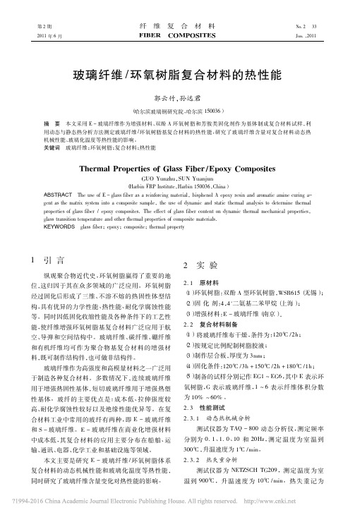
Bending,compression,and shear behavior of woven glass ®ber±epoxycompositesB.Yang a ,V.Kozey a ,S.Adanur b ,S.Kumar a,*aSchool of Textile and Fiber Engineering,Georgia Institute of Technology,Atlanta,GA 30332,USAbDepartment of Textile Engineering,Auburn University,Auburn,AL 36849,USAReceived 20May 1999;accepted 25August 1999AbstractThe mechanical properties and failure mechanisms of through-the-thickness stitched plain weave glass fabric±epoxy composites were studied.Unstitched plain weave and biaxial non-crimp fabrics were used for posite panels were fabricated using Resin Transfer Molding.Z -directional stitching increased the delamination resistance and lowered the bending strength of the posites made from through-the-thickness stitched fabrics demonstrated improved compression after impact behavior as compared to the unstitched fabrics.The results presented in this investigation should be useful in tailoring textile composites to achieve speci®c property goals.q 2000Elsevier Science Ltd.All rights reserved.Keywords :Bending1.IntroductionTextile technologies such as weaving,stitching,braiding,knitting are being employed to fabricate advanced compo-sites with conformability,quality and integrated mechanical properties [1±10].One of the objectives of using textile reinforcement is to take advantage of through-the-thickness arrangement of ®bers to enhance interlaminar strength and toughness,compressive strength,as well as compression-after-impact (CAI)strength [11±13].Reinforcing ®bers in the thickness direction also contribute to stiffness and strength in that direction.Research efforts to improve interlaminar fracture behavior have generally focused in the following areas:(i)the reinforcement material,for example,the development of three-dimensional (3D)preforms;(ii)the use of tough matrix material such as PEEK [14];(iii)the addition of micro®ber [15];and (iv)developing good ®ber±matrix interface with the use of improved coupling agents for controlled interfacial properties.The improved interlaminar shear property in the thickness direction gives much improved fracture and impact resistance over the conven-tional laminates.The compressive response of ®ber-reinforced compositeshas been the subject of continued investigation [9,16±18].Many factors in¯uence the compressive response of compo-site materials.These include the compressive properties of the ®ber [19]and the matrix [20]as well as the ®ber±matrix interface.The presence of local inhomogeneities and defects,which are often dif®cult to characterize and model,also in¯uence the failure in compression.On a macrostructure level,laminate orientation,specimen geometry,method of loading and stress concentrations are some of the factors that play a role in determining the compression failure mode.Conventional laminate composites are sensitive to out-of-plane loading,as they are weaker in the through-the-thick-ness direction than in the plane of lamination.Therefore,to improve interlaminar properties,multi-layer continuous glass ®ber textile preforms have been stitched using Kevlar yarn.Epoxy has been used as the matrix material.The objective of this research is to study the relationship among textile preform architecture,mechanical proper-ties,and the resulting failure modes.Signi®cant attention was focused on the compressive response of the textile composites.2.Materials and sample preparationThe following E-glass reinforcements were used in this study:(1)non-crimp biaxial laminate (LM)with glass ®berComposites:Part B 31(2000)715±7211359-8368/00/$-see front matter q 2000Elsevier Science Ltd.All rights reserved.PII:S1359-8368(99)00052-9/locate/compositesb*Corresponding author.Tel.:11-404-894-7550;fax:11-404-894-8780.E-mail address:satish.kumar@ (S.Kumar).in the0and908direction;(2)plain weave fabric(PW);and (3)through-the-thickness biaxial(BS)or uniaxial stitched (US)plain weave fabrics.The non-crimp biaxial laminate fabric,containing1%polyester yarn and99%E-glass,was obtained from Tech Textiles USA.The polyester yarn (usually70or150denier)was used to stitch bond the glass®ber layers.The plain weave fabric of E-glass was obtained from PPG.The ratio of warp to®lling yarn was approximately1.3:1.Woven fabric structures result in inherent®ber waviness.A156denier Kelvar e yarn was used for stitching the plain weave fabric layers in the thick-ness direction(denier is the weight of9000m length of yarn in grams).Three and six layers of plain weave fabrics were stitched.The stitching lines were2,5,10,15,and20mm apart.In all cases,both uniaxial and biaxial stitching modes were used.Kelvar e stitching yarn accounted for less than 3%of the total woven fabric weight.Various samples tested are listed in Table1.The glass preform containing three,six,or12layers was placed in the steel mold.The mold dimension was25:4£30:5£z cm3:The sample thickness varied between0.18and 0.63mm.Two different molds and an aluminum plate were used for varying sample thickness.There were two nozzles in the mold,one for resin injection and the other one for vacuum line to remove air bubbles.Some of the excess resin was also removed through the vacuum nozzle.The mold was impregnated with the epoxy resin(EPON862and the curing agent W in the weight ratio100:26).Both compo-nents of the epoxy were obtained from Shell Chemical Co. Before injecting in the mold,the epoxy resin was heated to approximately458C.The equipment used was a VRM2.5 Resin Transfer Molding machine from Liquid Control Corporation.The system was totally enclosed and the mixing of resin and curing agent only took place at the ®nal stage with the mixing chamber at the point of dispen-sing in the mold.After resin transfer,the specimen was cured at1258C for6h.Density was measured by weighing the composite samples in air and in water.Fiber volume fraction was determined using the following equation:r c r f V f1r m V m where r is the density and V the volume fraction.The presence of voids was not accounted for.Subscripts c,f, and m refer to composite,®ber and matrix,respectively. The density of the®ber and matrix were taken to be2.58 and1.2g cm3,respectively.For the stitched and unstitched woven samples,three,six,and12fabric layers were used for the bending,compression,and grooved shear tests, respectively.To achieve comparable thickness,for the non-crimped laminate samples,six and12plies were used for the bending and compression tests,respectively.3.Mechanical testingThe following test methods were used to determine the interlaminar shear strength:(i)short beam shear test(ASTM D2355);and(ii)tensile testing of grooved coupons(ASTM D2677).The length-to-depth l=d ratio in the short beam shear test was approximately5.The thickness of the grooved coupon was7.2mm,groove depth was3.5mm and the distance between the grooves was20mm.Low-velocity impact was applied to the specimen using a small pendulum apparatus.The diameter of the hemi-spherical impactor was10mm.The impact energy ranged from0to8.7J,and this corresponds to0±2.5J mm21of the sample thickness.Impact loading produced near-circular damage areas.These samples were subsequently used for compression after impact and bending after impact testing. Bending strength was measured according to the ASTM 790-91test method.The three-point loading scheme was selected,and the test was performed using Instron5500 universal testing machine.The length to depth ratio was 40:pressive strength was determined using the IITRI method(ASTM D3410).The sample dimensions were120£40£z mm3;and the gauge length was25mm.4.Results and discussion4.1.Interlaminar shear strengthInitially attempt was made to determine the interlaminar shear strength using the short beam shear test.However,it was observed that the short-beam shear specimens of the unstitched fabric composites did not develop shear cracking in the mid-plane of the specimens as required in the ASTM test.Apparent shear strength of47MPa was calculated for this composite,however,both the upper and lower surfaces underwent extensive damage.Damage in the upper surface of the beam is from compressive failure;damage in the lower surface is from tensile failure.There was no indi-cation of shear failure or crack initiation in the mid-plane. Furthermore,®ber unevenness deterred fabric plane slippage,and additional through-the-thickness stitching practically eliminated the possibility of inter-plane slippage. Thus,interlaminar failure was not observed.Based on these observations,it was concluded that the short-beam shear testB.Yang et al./Composites:Part B31(2000)715±721 716Table1Description of the sample codesSample code Sample descriptionLM Non-crimp laminatePW Plain WeaveUS2Uniaxial stitching2mm apartUS5Uniaxial stitching5mm apartUS10Uniaxial stitching10mm apartUS20Uniaxial stitching20mm apartBS2Biaxial stitching2mm apartBS5Biaxial stitching5mm apartBS10Biaxial stitching10mm apartBS20Biaxial stitching20mm apartis not appropriate for the shear testing of these woven fabric composites.Shear testing was therefore done using the grooved coupon test.In comparison to the short beam shear test,the grooved coupon test is purely in a state of Mode II loading.In the grooved coupon specimens,shear cracking initiates around the notch and propagated between the fabric layers.The failed samples were characterized by the full-length delamination along the plane between the grooves.Table 2lists the data on interlaminar shear strength of 2D woven and through-the-thickness stitched woven compo-sites measured using the grooved test.Two factors affect grooved coupon test results:(i)shear stress concentration predominantly develops around the grooves;and (ii)shear strength measured by the grooved coupon test also varies depending on the precision of the cut of the grooves.Some tearing in the composite takes place during the testing of undercut specimens.Bending and peeling also occurs especially for the overcut specimen.Z -directional kevlar yarn used in stitching ®ber appears to resist shear crack development.Table 2shows that increasing density of Z -directional stitching yarn moderately increases the delami-nation resistance of the composite.The crack surface was clear and smooth for the plane weave fabric composite asseen in Fig.1,which represents poor adhesion between ®ber and the matrix.4.2.Bending strengthBending and bending-after-impact strength data is presented in Table 3.In general,stitching adversely affect the bending behavior.Higher stitching density lowers the bending strength.Three-point bending load versus displace-ment curves for the unstitched samples were characterized by ªkneeºeffect and non-linearity.Similar load±displace-ment behavior is also reported for this sample in tensile test [21].The non-linearity is caused primarily by a structural change in the fabric during deformation.ªKneeºeffect occurs,when layers,whose ®lament axes are perpendicular to the loading direction,crack or break.Bending curve for uniaxial and biaxial stitched composites in general are different from those of the unstitched plain weave compo-sites.Densely stitched samples did not exhibit ªkneeºeffect.Bending test showed that the outer layer fracture along the beam axis led to the ®nal failure.A closer observation of the specimen showed that there was some visible damage on the compressive side.As loading progressed,cracking ®rst developed in outer ply on the tensile side.Microcracking initiated when the stress exceeded the local matrix pocket strength.4.3.Impact damage analysisThe impact damage zone is generally complex in nature and consequently not easy to characterize [22].Due to the lack of existing standards or the established test techniques for impact damage of composite materials,direct compar-ison of data for various material systems reported in the literature are often misleading.We have determined impact damage using a pendulum tester,which generated approxi-mately round-shape damaged areas.Three energy levels,i.e.0,1.65,2.5J mm 21,were used in the present study.Damage area increased with the increasing impact energy.At the impact point on the surface of the specimen,the damage consisted primarily of crushed material with some delami-nation between plies at the interface.A cone of damage was formed beneath the point of impact.The amount of crushed material decreased with increasing depth whereas the inter-laminar delamination increased.In specimen without through-the-thickness reinforcement,the damage cone angle was much smaller and damage area did not increase with the depth.An analysis suggests a number of damageB.Yang et al./Composites:Part B 31(2000)715±721717Table 2Interlaminar shear strength (from grooved coupon test)of woven glass±epoxy composites Sample code Number of plies Density (g cm 23)Fiber volume (%)Composite thickness (mm)Shear strength (MPa)PW 12 1.95567.216.0BS 1012 1.96567.217.0BS 5121.95577.218.2Fig.1.Scanning electron micrograph of shear crack (grooved coupon test)surface of unstitched woven glass±epoxy composite.mechanisms.These include delamination,®ber±matrix debonding,and interlaminar matrix cracking.The energy absorbing capability of composites depends on the properties of the constituents,and is re¯ected in the damage area.Table 4lists relative damage areas for various stitching density samples.It was clear that stitching reduces damage area and dense stitching is more effective in the damage area reduction.Signi®cantly higher damage area was observed in the laminate composites than the compo-sites made from the plain weave fabric.An interesting phenomenon is that increasing the thick-ness of the specimen resulted in an increase in the delami-nation area as can be seen from the results of three and six layer samples reported in Table 4.This increase in damage area may result from the reduction in energy absorbing capability as proposed by Dorey [23].It was suggested that the number of likely delamination sites increase with fabric thickness.More manufacturing defects and voids may be present in the thick pressive strengthCompression test results are given in Table 5and compressive stress±strain curves are shown in Fig.2.The results indicate that the 0/908non-crimp laminate has higher compressive strength as compared to the woven samples,aresult of ®ber waviness in the woven samples.The in¯uence of waviness parameters,such as wavelength and amplitude,on the compressive behavior has not been studied exten-sively.This study only describes some experimental obser-vations and shows qualitatively that the compressive strength decreases with the increasing ®ber misalignment or waviness.The different compressive response can also be re¯ected in the failure mode.Fig.3a shows the IITRI compression failure of the 0/908non-crimp pressive load-ing resulted in the formation of a shear band.There was no relative displacement of the ®bers across the failure zone,i.e.transverse movement across the failure band.Post-fail-ure examination showed that shear band was at 458angle toB.Yang et al./Composites:Part B 31(2000)715±721718Table 3Bending test results Sample code Density (g cm 23)Fiber volume (%)Composite thickness (mm)Bending strength (MPa)Bending strength after impact a (MPa)PW 1.7643 2.35370^13267^9BS 5 1.7140 2.50220^10211^8BS 2 1.7140 2.51233^9215^3US 20 1.7241 2.53326^9247^6US 5 1.7140 2.52198^3180^5US 21.7392.50177^6174^4aBending strength after impact (energy level 2.5J mm 21).Table 4Relative impact damage (impact energy 2.5J mm 21)areas in woven lami-nate composites Sample codeDamage area (%)Three layer compositeSix layer composite PW 100(283mm 2)100(414mm 2)BS 208784US 208786BS 104350US 10±54BS 52839US 53343BS 222US 226±±140pressive stress±strain curves for glass ®ber±epoxy composites:(a)non-crimp 0/908laminate (LM)composite;(bi)plain weave (PW)unstitched composite;(bii)uniaxially (US5)stitched composite;and (biii)biaxially stitched (BS5)composite.the loading direction.Samples failing in this mode yielded high compressive strength values.Fig.3b shows the IITRI compression failure in the plain weave fabric composite.The damage appears to be initiated by interlaminar stress,generated by the waviness of ®ber.These interlaminar stresses appear to cause local delamin-ation in the sample,thereby reducing the local transverse support for the ®bers.The ®bers in adjacent region of low waviness were thus likely to be overloaded.Finally,global microbuckling can be observed in these composites.Delamination and global buckling are in fact a bending fail-ure due to interlaminar posites failing in this mode yielded relatively low compressive strength.The compressive failure in the composites made from loosely stitched woven fabrics was comparable to that of the unstitched fabric composites.However,the dense stitch-ing appeared to have different failure mode.Fig.3c shows typical failure mechanism for the densely stitched biaxial woven composite.Localized failure in the form of a kink band can be seen in the crack initiation.Argon [24]suggested that the regions in a composite in which ®bers are not aligned with the compression axis would form a failure nucleus that undergoes kink band formation.pression-after-impact strengthAs discussed previously,impact damage area is a func-tion of impact energy.The CAI strength is very much dependent on the impact pression-after-impact data at two energy levels (1.65and 2.5J mm 21)are reported in Table 5.It is seen that compressive strength of un-damaged laminate is 15%higher than that of the composite from woven fabric.However,after being subjected to impact energy of 2.5J mm 21,CAI strength of woven fabric composite was up to 37%higher than that of the laminate.CAI of 5mm spacing biaxial stitched woven specimen was over 60%higher as compared to the laminate composites.This dramatic reversal in the structural performance of the glass±epoxy composite materials is consistent with published results for graphite±epoxy composites [25].The specimens with stitched through-the-thickness reinforce-ment exhibited higher CAI strength than the unstitched woven fabrics did.Loose stitching was not much effective in improving the CAI strength.The macroscopic failure modes of CAI samples are different from the compression behavior of undamaged samples.Fig.4a shows interlaminar splitting mode in aB.Yang et al./Composites:Part B 31(2000)715±721719pressive failure in:(a)non-crimp laminate composite;(b)unstitched woven composite;and (c)biaxial stitched (stitching lines 5mm apart)woven composite.Table 5Static compressive strength of glass ®ber±epoxy composites using IITRI test Sample codes Density (g cm 23)Fiber volume (%)Composite thickness (mm)Compressive strength (MPa)CAI a strength (MPa)CAI b strength (MPa)LM 1.9053 4.41438^10176^7139^4PW 1.9858 4.40380^8195^2190^11US 20 2.0059 4.40380^6187^6180^10BS 20 1.9053 4.58386^16192^10±US 10 2.059 4.35385^5192^2186^5BS 10 1.9355 4.55398^8256^8192^11US 5 1.9556 4.40400^9223^1207^10BS 51.95564.60427^8300^11223^8a Impact 1.65J mm 21.bImpact energy 2.5J mm 21.laminate composite.Interlaminar crack is caused due to the delamination in the impact damaged region.For unstitched woven and loosely stitched sample,the CAI fracture is mix-mode as shown in Fig.4b.Crack was caused by the buckling±bending close to the damaged region,followed by debonding.Loose stitching has played no obvious role in moderating failure propagation.Fig.4c shows kink failure for densely stitched sample.The kink band in the damage sample propagated through the sample thickness at an angle of 378rather than the 458angle in the undamaged composite.5.ConclusionsThere is no clear evidence of cracking in the mid-plane of woven glass ®ber±epoxy composites during the short beam shear (SBS test).The grooved coupon test for interlaminar shear strength shows that increasing density of Z -directional stitching ®bers will moderately increase the delamination resistance of the posites of stitched 2D woven samples exhibited lower bending strength as compared to the unstitched samples.Z -directional stitching is effective in reducing the impact damage.The compressive strength of the non-crimp laminate samples is about 15%higher than that for the woven fabric composite,a result of waviness in the woven fabric compo-sites.At high stitching density,CAI has been signi®cantly pression failure modes for the variety of ®ber arrangements are different.The experimentally observed shear failure of ®ber across the specimen thickness was the failure mechanism of laminate composites.Delami-nation,followed by microbuckling and global buckling is the failure observed in woven fabric composites.The densely stitched composites appear to fail via kinking followed by ®ber buckling.CAI samples display different fracture mechanisms.Interlaminar splitting is the dominant mode of fracture inunstitched woven fabrics and laminate composites.Densely stitched samples showed shear failure via kinking.AcknowledgementsThis work was supported by the US Department of Commerce through the National Textile Center (Grant no.99-27-07400).References[1]Miravete A.3-D Textile reinforcements in composite materials.BocaRaton,FL:CRC Press,1999.[2]Chou TW.Microstructural design of ®ber composites.Cambridge,UK:Cambridge University Press,1992.[3]Guenon VA,Chou TW,Gillespie JW.Interlaminar fracture toughnessof a three-dimensional fabric composite.Proceedings of the Society of Manufacturing Engineers,Dearborn MI 1987;EM-87-551:1±17.[4]Liu CH,Chou TW.Mode II interlaminar fracture toughness of threedimensional textile structural composites,Proceedings of the fourth Japan±US conference on composite materials.Washington:Tech-nomic Publishing Co,1989.p.981.[5]Byun JH,Gillespie JW,Chou TW.Mode I delamination of a three-dimensional fabric composite.J Comp Mater 1990;24:497.[6]Guenon VA,Chou TW,Gillespie JW.Toughness properties of athree-dimensional carbon-epoxy composite.J Mater Sci 1989;24:4168.[7]Kregers AF,Teters GA.Structural model of deformation of anisotro-pic three dimensionally reinforced composites.Mech Comp Mater 1982;1:14.[8]Ko FK,Pastore CM.Structure and properties of an integrated 3-Dfabric for structural composites,ASTM STP 864.Philadelphia,PA:American Society of Testing and Materials,1985.p.428.[9]West AC,Adams DO.Effect of yarn crimping on compressivestrength design allowables of braided composites,Proc Am Soc CompÐXIth Tech ncaster,PA:Technomic Publishing Co,1996.p.999.[10]Naik RA,Ifju PG,Masters JE.Effects of ®ber architecture parameterson deformation ®elds and elastic moduli of 2-D braided composites.J Comp Mater 1994;28:656.[11]Kozey VV,Kumar S,Adanur S,Mohamed M.Proc 26th InternationalSAMPE Tech.Conf.Covina,CA,1994.p.315.B.Yang et al./Composites:Part B 31(2000)715±721720Fig.4.Failure in CAI samples:(a)non-crimp laminate composite;(b)unstitched woven composite;and (c)biaxial stitched (stitching lines 5mm apart)woven composite.Impact energy in each sample,2.5J mm 21.[12]Arendts FJ,Drechsler K,Brandt J.Proc34th International SAMPESym.Covina,CA,1989,vol.129.p.2118[13]Morales A.Proc.22nd International SAMPE Tech.Conf.Covina,CA,1990.[14]Yau S,Chou TW.Strength of woven-fabric composites withdrilled and molded,Composites materials:testing and design (eighth conference),vol.972.Philadelphia,PA:ASTM STP, 1988.p.423.[15]Wang Y,Zhao D.Mechanical and interlaminar fracture properties ofwoven fabric reinforced composites.Proceeding of the39th Interna-tional SAMPE Symposium and Exhibition.Anaheim,CA,1994. [16]Adams DO,Bell pression strength reduction in compositelaminates due to multiple layer p Sci Technol 1995;53:207.[17]Kumar S,Adams WW,Helminiak TE.J Reinforced Plastics Comp1988;7:109.[18]Hahn HT,Sohi M,Moon S.NASA Contractor Report no.3988,June1986.[19]Kozey VV,Jiang H,Mehta VR,Kumar S.J Mater Res1995;10:1044.[20]Kozey VV,Kumar S.J Mater Res1994;9:2717.[21]Do PB.Effect of textile preform structure on the mechanical proper-ties and failure modes of composites from resin molding process.MS thesis.Georgia Institute of Technology,1994.[22]Avery JG.Design manual for impact damage tolerant aircraft struc-tures.AGAR DOGRAPH,no.238,NATO,1981.[23]Dorey G.Fracture of composites and damage tolerance in practicalconsideration of design,fabrication,and test for composites materials, AGARD Lecture series124,1982.[24]Argon JP,Guceri p Sci Tech1989;35:317±30.[25]Madan RC.In¯uence of low-velocity impact on composite structures.In:O'Brien TK,posite materials:fatigue and fracture, ASTM STP1110,1991.p.457.B.Yang et al./Composites:Part B31(2000)715±721721。