汽车制动器论文中英文对照资料外文翻译文献
- 格式:doc
- 大小:206.00 KB
- 文档页数:11
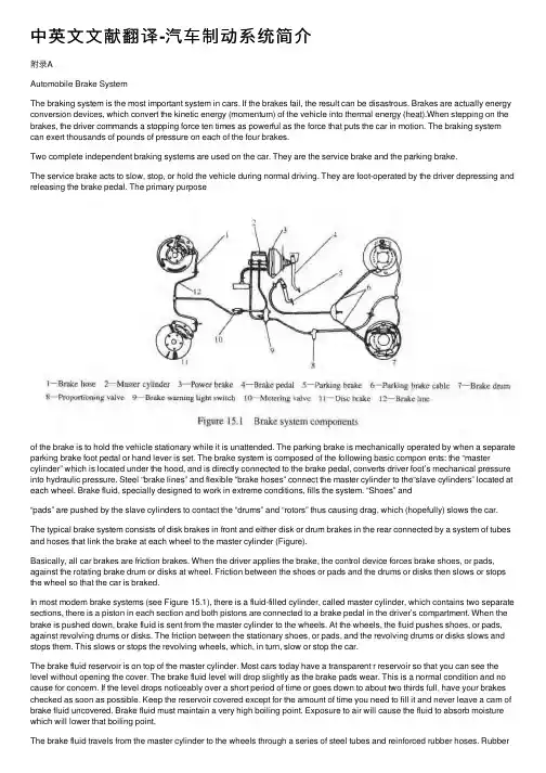
中英⽂⽂献翻译-汽车制动系统简介附录AAutomobile Brake SystemThe braking system is the most important system in cars. If the brakes fail, the result can be disastrous. Brakes are actually energy conversion devices, which convert the kinetic energy (momentum) of the vehicle into thermal energy (heat).When stepping on the brakes, the driver commands a stopping force ten times as powerful as the force that puts the car in motion. The braking system can exert thousands of pounds of pressure on each of the four brakes.Two complete independent braking systems are used on the car. They are the service brake and the parking brake.The service brake acts to slow, stop, or hold the vehicle during normal driving. They are foot-operated by the driver depressing and releasing the brake pedal. The primary purposeof the brake is to hold the vehicle stationary while it is unattended. The parking brake is mechanically operated by when a separate parking brake foot pedal or hand lever is set. The brake system is composed of the following basic compon ents: the “master cylinder” which is located under the hood, and is directly connected to the brake pedal, converts driver foot’s mechanical pressure into hydraulic pressure. Steel “brake lines” and flexible “brake hoses” connect the master cylinder to the“slave cylinders” located at each wheel. Brake fluid, specially designed to work in extreme conditions, fills the system. “Shoes” and“pads” are pushed by the slave cylinders to contact the “drums” and “rotors” thus causing drag, which (hopefully) slows the car. The typical brake system consists of disk brakes in front and either disk or drum brakes in the rear connected by a system of tubes and hoses that link the brake at each wheel to the master cylinder (Figure).Basically, all car brakes are friction brakes. When the driver applies the brake, the control device forces brake shoes, or pads, against the rotating brake drum or disks at wheel. Friction between the shoes or pads and the drums or disks then slows or stops the wheel so that the car is braked.In most modern brake systems (see Figure 15.1), there is a fluid-filled cylinder, called master cylinder, which contains two separate sections, there is a piston in each section and both pistons are connected to a brake pedal in the driver’s compartment. When the brake is pushed down, brake fluid is sent from the master cylinder to the wheels. At the wheels, the fluid pushes shoes, or pads, against revolving drums or disks. The friction between the stationary shoes, or pads, and the revolving drums or disks slows and stops them. This slows or stops the revolving wheels, which, in turn, slow or stop the car.The brake fluid reservoir is on top of the master cylinder. Most cars today have a transparent r reservoir so that you can see the level without opening the cover. The brake fluid level will drop slightly as the brake pads wear. This is a normal condition and no cause for concern. If the level drops noticeably over a short period of time or goes down to about two thirds full, have your brakes checked as soon as possible. Keep the reservoir covered except for the amount of time you need to fill it and never leave a cam of brake fluid uncovered. Brake fluid must maintain a very high boiling point. Exposure to air will cause the fluid to absorb moisture which will lower that boiling point.The brake fluid travels from the master cylinder to the wheels through a series of steel tubes and reinforced rubber hoses. Rubberhoses are only used in places that require flexibility, such as at the front wheels, which move up and down as well as steer. The rest of the system uses non-corrosive seamless steel tubing with special fittings at all attachment points. If a steel line requires a repair, the best procedure is to replace the compete line. If this is not practical, a line can be repaired using special splice fittings that are made for brake system repair. You must never use copper tubing to repair a brake system. They are dangerous and illegal. Drum brakes, it consists of the brake drum, an expander, pull back springs, a stationary back plate, two shoes with friction linings, and anchor pins. The stationary back plate is secured to the flange of the axle housing or to the steering knuckle. The brake drum is mounted on the wheel hub. There is a clearance between the inner surface of the drum and the shoe lining. To apply brakes, the driver pushes pedal, the expander expands the shoes and presses them to the drum. Friction between the brake drum and the friction linings brakes the wheels and the vehicle stops. To release brakes, the driver release the pedal, the pull back spring retracts the shoes thus permitting free rotation of the wheels.Disk brakes, it has a metal disk instead of a drum. A flat shoe, or disk-brake pad, is located on each side of the disk. The shoes squeeze the rotating disk to stop the car. Fluid from the master cylinder forces the pistons to move in, toward the disk. This action pushes the friction pads tightly against the disk. The friction between the shoes and disk slows and stops it. This provides the braking action. Pistons are made of either plastic or metal. There are three general types of disk brakes. They are the floating-caliper type, the fixed-caliper type, and the sliding-caliper type. Floating-caliper and sliding-caliper disk brakes use a single piston. Fixed-caliper disk brakes have either two or four pistons.The brake system assemblies are actuated by mechanical, hydraulic or pneumatic devices. The mechanical leverage is used in the parking brakes fitted in all automobile. When the brake pedal is depressed, the rod pushes the piston of brake master cylinder which presses the fluid. The fluid flows through the pipelines to the power brake unit and then to the wheel cylinder. The fluid pressure expands the cylinder pistons thus pressing the shoes to the drum or disk. If the pedal is released, the piston returns to the initial position, the pull back springs retract the shoes, the fluid is forced back to the master cylinder and braking ceases.The primary purpose of the parking brake is to hold the vehicle stationary while it is unattended. The parking brake is mechanically operated by the driver when a separate parking braking hand lever is set. The hand brake is normally used when the car has already stopped. A lever is pulled and the rear brakes are approached and locked in the “on” position. The car may now be left without fear of its rolling away. When the driver wants to move the car again, he must press a button before the lever can be released. The hand brake must also be able to stop the car in the event of the foot brake failing. For this reason, it is separate from the foot brake uses cable or rods instead of the hydraulic system.Anti-lock Brake SystemAnti-lock brake systems make braking safer and more convenient, Anti-lock brake systems modulate brake system hydraulic pressure to prevent the brakes from locking and the tires from skidding on slippery pavement or during a panic stop.Anti-lock brake systems have been used on aircraft for years, and some domestic car were offered with an early form of anti-lock braking in late 1990’s. Recently, several automakers have introduced more sophisticated anti-lock system. Investigations in Europe, where anti-lock braking systems have been available for a decade, have led one manufacture to state that the number of traffic accidents could be reduced by seven and a half percent if all cars had anti-lock brakes. So some sources predict that all cars will offer anti-lock brakes to improve the safety of the car.Anti-lock systems modulate brake application force several times per second to hold the tires at a controlled amount of slip; all systems accomplish this in basically the same way. One or more speed sensors generate alternating current signal whose frequency increases with the wheel rotational speed. An electronic control unit continuously monitors these signals and if the frequency of a signal drops too rapidly indicating that a wheel is about to lock, the control unit instructs a modulating device to reduce hydraulic pressure to the brake at the affected wheel. When sensor signals indicate the wheel is again rotating normally, the control unit allows increased hydraulic pressure to the brake. This release-apply cycle occurs several time per second to “pump” the brakes like a driver mig ht but at a much faster rate.In addition to their basic operation, anti-lock systems have two other things in common. First, they do not operate until the brakes are applied with enough force to lock or nearly lock a wheel. At all other times, the system stands ready to function but does not interfere with normal braking. Second, if the anti-lock system fail in any way, the brakes continue to operate without anti-lock capability. A warning light on the instrument panel alerts the driver when a problem exists in the anti-lock system.The current Bosch component Anti-lock Braking System (ABSⅡ), is a second generation design wildly used by European automakers such as BWM, Mercedes-Benz and Porsche. ABSⅡsystem consists of : four wheel speed sensor, electronic control unit and modulator assembly.A speed sensor is fitted at each wheel sends signals about wheel rotation to control unit. Each speed sensor consists of a sensor unit and a gear wheel. The front sensor mounts to thesteering knuckle and its gear wheel is pressed onto the stub axle that rotates with the wheel. The rear sensor mounts the rear suspension member and its gear wheel is pressed onto the axle. The sensor itself is a winding with a magnetic core. The core creates a magnetic field around the winding, and as the teeth of the gear wheel move through this field, an alternating current is induced in the winding. The control unit monitors the rate o change in this frequency to determine impending brake lockup.The control unit’s function can be divi ded into three parts: signal processing, logic and safety circuitry. The signal processing section is the converter that receives the alternating current signals form the speed sensors and converts them into digital form for the logic section. The logic section then analyzes the digitized signals to calculate any brake pressure changes needed. If impending lockup is sensed, the logic section sends commands to the modulator assembly.Modulator assemblyThe hydraulic modulator assembly regulates pressure to the wheel brakes when it receives commands from the control utuit. The modulator assembly can maintain or reduce pressure over the level it receives from the master cylinder, it also can never apply the brakes by itself. The modulator assembly consists of three high-speed electric solenoid valves, two fluid reservoirs and a turn delivery pump equipped with inlet and outlet check valves. The modulator electrical connector and controlling relays are concealed under a plastic cover of the assembly.Each front wheel is served by electric solenoid valve modulated independently by the control unit. The rear brakes are served by a single solenoid valve and modulated together using the select-low principle. During anti-braking system operation, the control unit cycles the solenoid valves to either hold or release pressure the brake lines. When pressure is released from the brake lines during anti-braking operation, it is routed to a fluid reservoir. There is one reservoir for the front brake circuit. The reservoirs are low-pressure accumulators that store fluid under slight spring pressure until the return delivery pump can return the fluid through the brake lines to the master cylinder.附录B汽车制动系统制动系统是汽车中最重要的系统。
3.1 ClutchThe engine produces the power to drive the vehicle. The drive line or drive train transfers the power of the engine to the wheels. The drive train consists of the parts from the back of the fl ywheel to the wheels. These parts include the clutch, the transmission, the drive shaft, and the final drive assembly.The clutch which includes the flywheel, clutch disc, pressure plate, springs, pressure plate cover and the linkage necessary to operate the clutch is a rotating mechanism between the engine and the transmission. It operates through friction which comes from contact between the parts. That is the reason why the clutch is called a friction mechanism. After engagement, the clutch must continue to transmit all engine torque to transmission depending on the friction without slippage. The clutch is also used to disengage the engine from the drive train whenever the gears in the transmission are being shifted from gear ratio to another.To start the engine or shift the gears, the driver has to depr ess the clutch pedal with the purpose of disengagement the transmission from the engine. At that time, the driven members connected to the transmission input shaft are either stationary or rotating at a speed that is slower of faster than the driving membe rs connected to engine crankshaft. There is no spring pressure on the clutch assembly parts. So there is no friction between the driving members and driven members. As the driver let’s loose the clutch pedal, spring pressure increase on the clutch parts. Friction between the parts also increases. The pressure exerted by the springs on the driven members is controlled by the driver through the clutch pedal and linkage. The positive engagement of the driving and driven members is made possible the friction be tween the surfaces of the members. When full spring pressure is applied, the speed of the driving and driven members should be the same. At themoment, the clutch must act as a coupling device and transmit all engine power to the transmission, without slipping.However, the transmission should be engaged to the engine graduall y in order to operate the car smoothly and minimize tensional shock on the drive train because an engine at idle just develop little power. Otherwise, the driving members are connecte d with the driven members too quickly and the engine would be stalled.The fl ywheel is a major part of the clutch. The flywheel mounts to the engine’s crankshaft and transmits engine torque to the clutch assembly. The flywheel, when coupled with the clutc h disc and pressure plate makes and breaks the flow of power the engine to the transmission.The flywheel provides a mounting location for the clutch assembly as well. When the clutch is applied, the fl ywheel transfers engine torque to the clutch disc. Because of its weight, the fl ywheel helps to smooth engine operation. The flywheel also has a large ring gear at its outer edge, which engages with a pinion gear on the starter motor during engine cranking.The clutch disc fits between the fl ywheel and the pressure plate. The clutch disc has a splinted hub that fits over splints on the transmission input shaft. A splinted hub has grooves that match splints on the shaft. These splints fit in the grooves. Thus, the two parts held together. However, back – and – forth movement of the disc on the shaft is possible. Attached to the input shaft, the disc turns at the speed of the shaft.The clutch pressure plate is generall y made of cast iron. It is round and about the same diameter as the clutch disc. One side of the pressure plate is machined smooth. This side will press the clutch disc facing are against the flywheel. The outer side has shapes to facilitate attachment of spring and release mechanism. The two primary t ypes of pressure plate assemblies are coil sp ring assembly and diaphragm spring.In a coil spring clutch the pressure plate is backed by a number of coil springs and housed with them in a pressed –steed cover bolted to the flywheel. The spring pushes against the cover. Neither the driven plate nor the pressure plate is connected rigidl y to the flywheel and both can move either towards it o away. When the clutch pedal is depressed a thrust pad riding on a carbon or ball thrust bearing is forced towards the flywheel. Levers pivoted so that they engage with the thrust pad at one end and the pressure plate tat the other end pull the pressure plate back against its springs. This releases pressure on the driven plate disconnecting the gearbox from the engine.Diaphragm spring pressure plate assemblies are widely used in most modern cars. The diaphragm spring is a single thin sheet of metal which yields when pressure is applied to it. When pressure is removed the metal spring back to its original shape. The center portion of the diaphragm spring is slit int o numerous fingers that act as release levers. When the clutch assembly rotates with the engine these weights are flung outwards by centrifugal plate and cause the levers to press against the pressure plate. During disengagement of the clutch the fingers are moved forward by the release bearing. The spring pivots over the fulcrum ring and its outer rim moves away from the flywheel. The retracting spring pulls the pressure plate away from the clutch plate thus disengaging the clutch.When engaged the release bearing and the fingers of the diaphragm spring move towards the transmission. As the diaphragm pivots over the pivot ring its outer rim forces the pressure plate against the clutch disc so that the clutch plate is engaged to flywheel.The advantages of a diaphragm t ype pressure plate assembl y are its compactness, lower weight, fewer moving parts, less effort to engage, reduces rotational imbalance by providing a balanced force around the pressure plate and less chances of clutch slippage.The clutch pedal is connected to the disengagement mechanismeither by a cable or, more commonly, by a hydraulic s ystem. Either way, pushing the pedal down operates the disengagement mechanism which puts pressure on the fingers of the clutch diaphragm via a release bearing and causes the diaphragm to release the clutch plate. With a hydraulic mechanism, the clutch pedal arm operates a piston in the clutch master cylinder. This forces hydraulic fluid through a pipe to the cutch release cylinder where another operates the c lutch disengagement mechanism by a cable.The other parts including the clutch fork, release bearing, bell –housing, bell housing cover, and pilot bushing are needed to couple and uncouple the transmission. The clutch fork, which connects to the linkage, actually operates the clutch. The release bearing fits between the clutch fork and the pressure plate assembly. The bell housing covers the clutch assembly. The bell housing cover fastens to the bottom of the bell housing. This removable cover allows a me chanic to inspect the clutch without removing the transmission and bell housing. A pilot bushing fits into the back of the crankshaft and holds the transmission input shaft.3.2 Brake SystemThe breaking system is the most important system in cars. If the brakes fail, the result can be disastrous. Brakes are actually energy conversion devices, which convert the kinetic energy (momentum) of the vehicle into thermal (heat). When stepping on the brakes, the driver commands a stopping force ten times as powerfu l as the force that puts the car in motion. The braking system can exert thousands of pounds of pressure on each of the four brakes.The brake s ystem is composed of the following basic components: the “master cylinder” which is located under the hood, and is directl yconnected to the brake pedal, converts driver foot’s mechanical pressure into hydraulic pressure. Steel “brake lines” and flexible “brake hoses” connect the master cylinder to the “slave cylinders” located at each wheel. Brake fluid, speciall y designed to work in extreme condition, fills the system. “Shoes” and “Pads” are pushed by the salve cylinders to contact the “drum” and “rotors” thus causing drag, which (hopefull y) slows the car.The typical brake system consists of disk brakes in front and either disk or drum brakes in the rear connected by a system of tubes and hoses that link the brake at each wheel to the master cylinder.Stepping on the brake pedal, a plunger is actually been pushing against in the master cylinder which forces hydr aulic oil (brake fluid) through a series of tubes and hoses to the braking unit at each wheel. Since hydraulic fluid (or any fluid for that matter) cannot be compressed, pushing fluid through a pipe is just like pushing a steel bar through pipe. Unlike a s teel bar, however, fluid can be directed through many twists and turns on its way to its destination, arriving with the exact same motion and pressure that it started with. It is very important that the fluid is pure liquid and that there is no air bubbles in it. Air can compress which causes sponginess to the pedal and severely reduced braking efficiency. If air is suspected, then the system must be bled to remove the air. There are “bleeder screws” at each wheel and caliper for this purpose.On disk brakes, the fluid from the master cylinder is forced into a caliper where it pressure against a piston. The piton, in-turn, squeezes two brake pads against the disk (rotor) which is attached to the wheel, forcing it to slow down or stop. This process is simila r to the wheel, causing the wheel to stop. In either case, the friction surface of the pads on a disk brake system, on the shoes on a drum brake convert the forward motion of the vehicle into heat. Heat is what causes the friction surfaces (lining) of the pads and shoes to eventually wear out andrequire replacement.Brake fluid is special oil that has specifics properties. It is designed to withstand cold temperatures without thickening as well as very high temperatures without boiling. (If the brake flui d should boil, it will cause you to have a spongy pedal and the car will be hard to stop).The brake fluid reservoir is on top of the master cylinder. Most cars today have a transparent reservoir so that you can see the level without opening the cover. Th e brake fluid lever will drop slightl y as the brake pads wear. This is a normal condition and no cause for concern. If the lever drops noticeabl y over a short period of time or goes down to about two thirds full, have your brakes checked as soon as possible. Keep the reservoir covered expect for the amount of time you need to fill it and never leave a can of brake fluid uncovered. Brake fluid must maintain a very high boiling point. Exposure to air will cause the fluid to absorb moisture which will lower th at boiling point.The brake fluid travels from the master cylinder to the wheels through a series of steel tubes and reinforced rubber hoses. Rubber hoses are onl y used in places that require flexibility, such as at the front wheels, which move up and dow n as well as steer. The rest of the system uses non-corrosive seamless steel tubing with special fittings at attachment points. If a steel line requires a repair, the best procedure is to replace the complete line. If this is nit practical, a line can be repaired using special splice fittings that are made for brake system repair. You must never use brass “compression” fittings or copper tubing repair a brake system. They are dangerous and illegal.3.2.1 Other Components in the Hydraulic System Proportioning Valve or Equalizer ValveThese valves are mounted between the master cylinder and the rear wheels. They are designed to adjust the pressure between the front and the rear brakes depending on how hard you are stopping. The shorter you stop, the mor e of the vehicle’s weight is transferred to the front wheels, in some cases, causing the rear to lift and the front to dive. These valves are designed to direct more pressure to the front and less pressure to the harder you stop. This minimizes the chance of premature lockup at the rear wheels.Pressure Differential ValveThis valve is usually mounted just below the master and is responsible for turning the brake warning light on when it detects a malfunction. It measures the pressure from the two sections of the master cylinder and compares them. Since it is mounted ahead of the proportioning or equalizer valve, the two pressures it detects should be equal. If it detects a difference, it means that there is probably a brake fluid leak somewhere in the syst em.3.1 离合器发动机产生动力来驱动汽车,它通过传动系把动力传递到车轮上,传动系包含从飞轮到车轮的所有零件。
毕业设计(论文)外文文献翻译文献、资料中文题目:汽车制动系统文献、资料英文题目:文献、资料来源:文献、资料发表(出版)日期:院(部):专业:汽车检测与维修班级:姓名:学号:指导教师:翻译日期: 2017.02.14Automobile Brake SystemThe braking system is the most important system in cars. If the brakes fail, the result can be disastrous. Brakes are actually energy conversion devices, which convert the kinetic energy (momentum) of the vehicle into thermal energy (heat).When stepping on the brakes, the driver commands a stopping force ten times as powerful as the force that puts the car in motion. The braking system can exert thousands of pounds of pressure on each of the four brakes.Two complete independent braking systems are used on the car. They are the service brake and the parking brake.The service brake acts to slow, stop, or hold the vehicle during normal driving. They are foot-operated by the driver depressing and releasing the brake pedal. The primary purpose of the brake is to hold the vehicle stationary while it is unattended. The parking brake is mechanically operated by when a separate parking brake foot pedal or hand lever is set.The brake system is composed of the following basic components: the “master cylinder” which is located under the hood, and is directly connected to the brake pedal, converts driver foot’s mechanical pressure into hydraulic pressure. Steel “brake lines” and flexible “brake hoses” connect the master cylinder to the “slave cylinders” located at each wheel. Brake fluid, specially designed to work in extreme conditions, fills the system. “Shoes” and “pads” are pushed by the slave cy linders to contact the “drums” and “rotors” thus causing drag, which (hopefully) slows the car.The typical brake system consists of disk brakes in front and either disk or drum brakes in the rear connected by a system of tubes and hoses that link the brake at each wheel to the master cylinder (Figure).Basically, all car brakes are friction brakes. When the driver applies thebrake, the control device forces brake shoes, or pads, against the rotating brake drum or disks at wheel. Friction between the shoes or pads and the drums or disks then slows or stops the wheel so that the car is braked.In most modern brake systems (see Figure 15.1), there is a fluid-filled cylinder, called master cylinder, which contains two separate sections, there is a piston in each section and both pistons are connected to a brake pedal in the driver’s compartment. When the brake is pushed down, brake fluid is sent from the master cylinder to the wheels.At the wheels, the fluid pushes shoes, or pads, against revolving drums or disks. The friction between the stationary shoes, or pads, and the revolving drums or disks slows and stops them. This slows or stops the revolving wheels, which, in turn, slow or stop the car.The brake fluid reservoir is on top of the master cylinder. Most cars today have a transparent r reservoir so that you can see the level without opening the cover. The brake fluid level will drop slightly as the brake pads wear. This is a normal condition and no cause for concern. If the level drops noticeably over ashort period of time or goes down to about two thirds full, have your brakes checked as soon as possible. Keep the reservoir covered except for the amount of time you need to fill it and never leave a cam of brake fluid uncovered. Brake fluid must maintain a very high boiling point. Exposure to air will cause the fluid to absorb moisture which will lower that boiling point.The brake fluid travels from the master cylinder to the wheels through a series of steel tubes and reinforced rubber hoses. Rubber hoses are only used in places that require flexibility, such as at the front wheels, which move up and down as well as steer. The rest of the system uses non-corrosive seamless steel tubing with special fittings at all attachment points. If a steel line requires a repair, the best procedure is to replace the compete line. If this is not practical, a line can be repaired using special splice fittings that are made for brake system repair. You must never use copper tubing to repair a brake system. They are dangerous and illegal.Drum brakes, it consists of the brake drum, an expander, pull back springs, astationary back plate, two shoes with friction linings, and anchor pins. The stationary back plate is secured to the flange of the axle housing or to th e steering knuckle. The brake drum is mounted on the wheel hub. There is a clearance between the inner surface of the drum and the shoe lining. To apply brakes, the driver pushes pedal, the expander expands the shoes and presses them to the drum. Friction between the brake drum and the friction linings brakes the wheels and the vehicle stops. To release brakes, the driver release the pedal, the pull back spring retracts the shoes thus permitting free rotation of the wheels.Disk brakes, it has a metal disk instead of a drum. A flat shoe, or disk-brake pad, is located on each side of the disk. The shoes squeeze the rotatin g disk to stop the car. Fluid from the master cylinder forces the pistons to move in, toward the disk. This action pushes the friction pads tightly against the disk. The friction between the shoes and disk slows and stops it. This provides the braking action. Pistons are made of either plastic or metal. There are three general types of disk brakes. They are the floating-caliper type, the fixed-caliper type, and the sliding-caliper type. Floating-caliper and sliding-caliper disk brakes use a single piston. Fixed-caliper disk brakes have either two or four pistons.The brake system assemblies are actuated by mechanical, hydraulic or pneumatic devices. The mechanical leverage is used in the parking brakes fitted in all automobile. When the brake pedal is depressed, the rod pushes the piston of brake master cylinder which presses the fluid. The fluid flows through the pipelines to the power brake unit and then to the wheel cylinder. The fluid pressure expands the cylinder pistons thus pressing the shoes to the drum or disk. If the pedal is released, the piston returns to the initialposition, the pull back springs retract the shoes, the fluid is forced back to the master cylinder and braking ceases.The primary purpose of the parking brake is to hold the vehicle stationary while it is unattended. The parking brake is mechanically operated by the driver when a separate parking braking hand lever is set. The hand brake is normally used when the car has already stopped. A lever is pulled and the rear brakes are approached and locked in the “on” position. The car may now be left without fearof its rolling away. When the driver wants to move the car again, he must press a button before the lever can be released. The hand brake must also be able to stop the car in the event of the foot brake failing. For this reason, it is separate from the foot brake uses cable or rods instead of the hydraulic system.Anti-lock Brake SystemAnti-lock brake systems make braking safer and more convenient, Anti-lock brake systems modulate brake system hydraulic pressure to prevent the brakes from locking and the tires from skidding on slippery pavement or during a panic stop.Anti-lock brake systems have been used on aircraft for years, and some domestic car were offered with an early form of anti-lock braking in late 1990’s. Recently, several automakers have introduced more sophisticated anti-lock system. Investigations in Europe, where anti-lock brakin g systems have been available for a decade, have led one manufacture to state that the number of traffic accidents could be reduced by seven and a half percent if all cars had anti-lock brakes. So some sources predict that all cars will offer anti-lock brakes to improve the safety of the car.Anti-lock systems modulate brake application force several times per second to hold the tires at a controlled amount of slip; all systems accomplish this in basically the same way. One or more speed sensors generate alternating current signal whose frequency increases with the wheel rotational speed. An electronic control unit continuously monitors these signals and if the frequency of a signal drops too rapidly indicating that a wheel is about to lock, the control unit instructs a modulating device to reduce hydraulic pressure to the brake at the affected wheel. When sensor signals indicate the wheel is again rotating normally, the control unit allows increased hydraulic pressure to the brake. This release-apply cycle occurs several time per second to “pump” the brakes like a driver might but at a much faster rate.In addition to their basic operation, anti-lock systems have two other things in common. First, they do not operate until the brakes are applied with enough force to lock or nearly lock a wheel. At all other times, the system stands ready tofunction but does not interfere with normal braking. Second, if the anti-lock system fail in any way, the brakes continue to operate without anti-lock capability. A warning light on the instrument panel alerts the driver when a problem exists in the anti-lock system.The current Bosch component Anti-lock Braking System (ABSⅡ), is a second generation design wildly used by European automakers such as BWM, Mercedes-Benz and Porsche. ABSⅡ system consists of: four wheel speed sensor, electronic control unit and modulator assembly.A speed sensor is fitted at each wheel sends signals about wheel rotation to control unit. Each speed sensor consists of a sensor unit and a gear wheel. The front sensor mounts to the steering knuckle and its gear wheel is pressed onto the stub axle that rotates with the wheel. The rear sensor mounts the rear suspension member and its gear wheel is pressed onto the axle. The sensor itself is a winding with a magnetic core. The core creates a magnetic field around the winding, and as the teeth of the gear wheel move through this field, an alternating current is induced in the winding. The control unit monitors the rate o change in this frequency to determine impending brake lockup.The control unit’s function can be divided into three p arts: signal processing, logic and safety circuitry. The signal processing section is the converter that receives the alternating current signals form the speed sensors and converts them into digital form for the logic section. The logic section then analyzes the digitized signals to calculate any brake pressure changes needed. If impending lockup is sensed, the logic section sends commands to the modulator assembly.Modulator assemblyThe hydraulic modulator assembly regulates pressure to the wheel brakes when it receives commands from the control utuit. The modulator assembly can maintain or reduce pressure over the level it receives from the master cylinder, it also can never apply the brakes by itself. The modulator assembly consists of three high-speed electric solenoid valves, two fluid reservoirs and a turn delivery pump equipped with inlet and outlet check valves. The modulator electrical connector and controlling relays are concealed under a plastic cover of the。
Automobile Brake SystemThe braking system is the most important system in cars. If the brakes fail, the result can be disastrous. Brakes are actually energy conversion devices, which convert the kinetic energy (momentum) of the vehicle into thermal energy (heat).When stepping on the brakes, the driver commands a stopping force ten times as powerful as the force that puts the car in motion. The braking system can exert thousands of pounds of pressure on each of the four brakes.Two complete independent braking systems are used on the car. They are the service brake and the parking brake.The service brake acts to slow, stop, or hold the vehicle during normal driving. They are foot-operated by the driver depressing and releasing the brake pedal. The primary purpose of the brake is to hold the vehicle stationary while it is unattended. The parking brake is mechanically operated by when a separate parking brake foot pedalor hand lever is set.The brake system is composed of the following basic components: the “master cylinder” which is located under the hood, and is directly connected to the brake pedal, converts driver foot’s mechanical pressure into hydraulic pressure. Steel “brake lines” and flexible “brake hoses” connect the master cylinder to the “slave cylinders” located at each wheel. Brake fluid, specially designed to work in extreme conditions, fills the system. “Shoes” and “pads” are pushed by the slave cylinders to contact the “drums” and “rotors” thus causing drag, which (hopefully) slows the car.The typical brake system consists of disk brakes in front and either disk or drum brakes in the rear connected by a system of tubes and hoses that link the brake at each wheel to the master cylinder (Figure).Basically, all car brakes are friction brakes. When the driver applies the brake, the control device forces brake shoes, or pads, against the rotating brake drum or disks at wheel. Friction between the shoes or pads and the drums or disks then slows or stops the wheel so that the car is braked.In most modern brake systems (see Figure 15.1), there is a fluid-filled cylinder, called master cylinder, which contains two separate sections, there is a piston in each section and both pistons are connected to a brake pedal in the driver’s compartment. When the brake is pushed down, brake fluid is sent from the master cylinder to the wheels.At the wheels, the fluid pushes shoes, or pads, against revolving drums or disks. The friction between the stationary shoes, or pads, and the revolving drums or disks slows and stops them. This slows or stops the revolving wheels, which, in turn, slow or stop the car.The brake fluid reservoir is on top of the master cylinder. Most cars today have a transparent r reservoir so that you can see the level without opening the cover. The brake fluid level will drop slightly as the brake pads wear. This is a normal condition and no cause for concern. If the level drops noticeably over ashort period of time or goes down to about two thirds full, have your brakes checked as soon as possible. Keep the reservoir covered except for the amount of time you need to fill it and never leave a cam of brake fluid uncovered. Brake fluid must maintain a very high boiling point. Exposure to air will cause the fluid to absorb moisture which will lower that boiling point.The brake fluid travels from the master cylinder to the wheels through a series of steel tubes and reinforced rubber hoses. Rubber hoses are only used in places that require flexibility, such as at the front wheels, which move up and down as well as steer. The rest of the system uses non-corrosive seamless steel tubing with special fittings at all attachment points. If a steel line requires a repair, the best procedure is to replace the compete line. If this is not practical, a line can be repaired using special splice fittings that are made for brake system repair. You must never use copper tubing to repair a brake system. They are dangerous and illegal.Drum brakes, it consists of the brake drum, an expander, pull back springs, a stationary back plate, two shoes with friction linings, and anchor pins. The stationary back plate is secured to the flange of the axle housing or to the steering knuckle. The brake drum is mounted on the wheel hub. There is a clearance between the inner surface of the drum and the shoe lining. To apply brakes, the driver pushes pedal, the expander expands the shoes and presses them to the drum. Friction between the brake drum and the friction linings brakes the wheels and the vehicle stops. To releaseAnti-lock brake systems make braking safer and more convenient, Anti-lock brake systems modulate brake system hydraulic pressure to prevent the brakes from locking and the tires from skidding on slippery pavement or during a panic stop.Anti-lock brake systems have been used on aircraft for years, and some domestic car were offered with an early form of anti-lock braking in late 1990’s. Recently, several automakers have introduced more sophisticated anti-lock system. Investigations in Europe, where anti-lock brakin g systems have been available for a decade, have led one manufacture to state that the number of traffic accidents could be reduced by seven and a half percent if all cars had anti-lock brakes. So some sources predict that all cars will offer anti-lock brakes to improve the safety of the car.Anti-lock systems modulate brake application force several times per second to hold the tires at a controlled amount of slip; all systems accomplish this in basically the same way. One or more speed sensors generate alternating current signal whose frequency increases with the wheel rotational speed. An electronic control unit continuously monitors these signals and if the frequency of a signal drops too rapidly indicating that a wheel is about to lock, the control unit instructs a modulating device to reduce hydraulic pressure to the brake at the affected wheel. When sensor signals indicate the wheel is again rotating normally, the control unit allows increased hydraulic pressure to the brake. This release-apply cycle occurs several time per second to “pump” the brakes like a driver might but a t a much faster rate.In addition to their basic operation, anti-lock systems have two other things in common. First, they do not operate until the brakes are applied with enough force to lock or nearly lock a wheel. At all other times, the system stands ready to function but does not interfere with normal braking. Second, if the anti-lock system fail in any way, the brakes continue to operate without anti-lock capability. A warning light on the instrument panel alerts the driver when a problem exists in the anti-lock system.The current Bosch component Anti-lock Braking System (ABSⅡ), is a second generation design wildly used by European automakers such as BWM,Mercedes-Benz and Porsche. ABSⅡsystem consists of : four wheel speed sensor, electronic control unit and modulator assembly.A speed sensor is fitted at each wheel sends signals about wheel rotation to control unit. Each speed sensor consists of a sensor unit and a gear wheel. The front sensor mounts to the steering knuckle and its gear wheel is pressed onto the stub axle that rotates with the wheel. The rear sensor mounts the rear suspension member and its gear wheel is pressed onto the axle. The sensor itself is a winding with a magnetic core. The core creates a magnetic field around the winding, and as the teeth of the gear wheel move through this field, an alternating current is induced in the winding. The control unit monitors the rate o change in this frequency to determine impending brake lockup.The control unit’s function can be divided into three parts: signal processing, logic and safety circuitry. The signal processing section is the converter that receives the alternating current signals form the speed sensors and converts them into digital form for the logic section. The logic section then analyzes the digitized signals to calculate any brake pressure changes needed. If impending lockup is sensed, the logic section sends commands to the modulator assembly.Modulator assemblyThe hydraulic modulator assembly regulates pressure to the wheel brakes when it receives commands from the control utuit. The modulator assembly can maintain or reduce pressure over the level it receives from the master cylinder, it also can never apply the brakes by itself. The modulator assembly consists of three high-speed electric solenoid valves, two fluid reservoirs and a turn delivery pump equipped with inlet and outlet check valves. The modulator electrical connector and controlling relays are concealed under a plastic cover of the assembly.Each front wheel is served by electric solenoid valve modulated independently by the control unit. The rear brakes are served by a single solenoid valve and modulated together using the select-low principle. During anti-braking system operation, the control unit cycles the solenoid valves to either hold or release pressure the brake lines. When pressure is released from the brake lines during anti-braking operation, it is routed to a fluid reservoir. There is one reservoir for the front brake circuit. The reservoirs are low-pressure accumulators that store fluid under slight spring pressure until the return delivery pump can return the fluid through the brake lines to the master cylinder.汽车制动系统制动系统是汽车中最重要的系统。
中英文对照外文翻译文献(文档含英文原文和中文翻译)外文:An Experimental Analysis of Brake Efficiency Using fourFluids in a Disc Brake SystemABSTRACTThe paper studies disc brake failure in Mini-buses using an experimental analysis to test the maximum braking force when different brake fluids such as clean, less dirty, dirty and soapy water solution were used in the braking system. The experimental results clearly showed that the soap solution appears to be the best fluid as far as low viscosity and stability of viscosity with increase in temperature are concerned. However, the soap solution is not compatible with other fluid which makes it difficult to be substitute as a clean brake fluid. The result of the Thepra Universal Brake Testing Equipment used for the braking efficiency test indicated that a pedal brake of 117 kN produce a brake force of 0.96 kN for clean brake fluid, 0.91 kN for the less dirty, 0.85 kN for dirty and 1.44 kN forsoap solution. The value of 1.44 kN which was achieved when the soap solution was used indicated a positive braking force and the indicating that soap solution could be used to produce a high pedal force within a very short time (about 10-30 min) and can therefore be used only in case of emergency. The brake efficiency test indicated that under hot conditions the braking efficiency is reduced and the presence of air in the system renders the braking ineffective because higher pedal force was needed to be able to produce a significant braking force which is noted for causing brake failure.Keywords: Brake fade, brake failure, disc brake, efficiency, pedal force INTRODUCTIONWhen a vehicle is accelerated, energy supplied by the engine causes the vehicle’s speed to increase. Part of this energy is instantly used up in overcoming frictional and tractive resistance but a large amount of it remains stored in the vehicle. According to Heinz (1999) this energy of motion is called the kinetic energy and the existence of kinetic energy is observed when a vehicle is moving and neutral gear is selected. The vehicle does not immediately come to rest; instead it travels for a considerable distance before it becomes stationary. In this case the stored energy is used to drive the vehicle against the resistances that oppose the vehicle’s motion. Relying on these r esistances to slow down a vehicle could cause many problems, so an additional resistance called a brake is needed to convert the kinetic energy to heat energy at a faster rate in order to reduce the speed of the vehicle Mcphee and Johnson (2007). This reduces the speed of the vehicle at a faster rate and brings the vehicle to rest within the shortest possibletime when the brakes are applied.From the point of view of Johnson et al. (2003) most automotive systems in use today utilize front disc brakes, but four-wheel disc systems are also common In disc brakes, the rotor rotates with the wheel and the pads move out to rub the rotor when the brakes are applied. Most disc brakes use floating calipers. The caliper slides in and out as the brakes are applied and released. The piston moves the inside pad out and pushes the outside pad into the rotor by sliding the caliper back toward the rotor.The use of disc brakes to reduce speed or bring the vehicle to rest when in motion cannot be over emphasized if the safety of the occupant is to be guaranteed Heinz (1999). To bring a vehicle to a stop, the disc brakes have to absorb all the energy given to thevehicle by the engine and that due to the momentum of the vehicle. This energy must then be dissipated. In most vehicle disc brakes, the energy is absorbed by friction, converted into heat and the heat dissipated to the surrounding air (Thoms, 1988). As the energy is absorbed, the vehicle is slowed down; in other words, its motion is retarded. The brakes must also pull up the vehicle smoothly and in a straight line to bring the vehicle to a stop position.It is therefore very important that the disc brakes of vehicles operate with the highest efficiency. This couldreduce the rate of accidents due to brake failure so that life and property could be preserved and also to ensure that occupants of these commercial vehicles go about their normal lives without any fear of being involved in an accident. Available crash data in Ghana suggests that about 1,900 persons are killed annually in road traffic crashes (Afukaar et al., 2008) and that more than 40% of the road traffic fatalities are occupants of cars, buses and trucks. Most often than not, some of the road accidents involving commercial vehicles, such as the mini-buses have been attributed to the failure of the disc brakes. The reason for testing the viscosity of these brake fluids, especially that of the soap solution was as a result of the practice of most Ghanaian drivers sometimes using the soapy solution as a substitute to the original brake fluid in the braking system and also using dirty brake fluid which has been used for bleeding purposes. The main objective of this study which is part of a larger work seeks to investigate and establish the reasons for the disc brake failure due to brake fluid also check the efficiency of the four different types of fluids used in the transmission of braking forces. The study looked at the maximum braking force when using clean, less dirty, dirty and soapy water solution in the braking system. It also looked at the braking force when the braking system is with or without servo unit and operating under cold or hot condition with air or without air in the braking systemDISC BRAKESThe disc brake consists of an exposed disc which is attached to the hub flange; the two friction pads arepressed on to this disc to give a braking action. Figure 1a, shows the disk brake system of a car and pad that is separated from wheel assembly to better shows the disk and the pad in sliding contact. As it can be seen, typical disk brake system and caliper assembly of a solid disk brake rotor is completely noticeable. Figure 1b shows schematic form of the disk and the pad in sliding contact assembly.(a) (b)Fig. 1: Disc brakeThe pads are moved by hydraulic pistons working in cylinders formed in a caliper that is secured to a fixed part of the axle. When the hydraulic pressure is applied to the two cylinders held in the fixed caliper, the pistons move; this action forces the friction pads into contact with the rotating cast iron disc. The sandwiching action of the pads on the disc gives a retarding action and heat generated from the energy of motion is conducted to the disc.Greater part of the disc is exposed to the air; therefore heat is easily radiated, with the result that the brake can be used continuously for long periods before serious fade occurs. Since the friction pads move at a right angle to the disc, any drop in the friction value does not affect the force applied to the pad. As a result this type of brake is not less sensitive to heat (Mudd, 1972). The disc brake was developed to minimize the fade problems. When fading occurs, the driver has to apply a much larger effort and in extreme cases it becomes impossible to bring the vehicle to rest. No assistance is obtained from the rotating disc to aid the driver in the application of a disc brake to achieve a given retardation. A disc brake requires a greater pedal pressure and toachieve this pressure required the hydraulic braking system using a good quality brake fluid in its operation.The fluid used in the hydraulic braking systems is a vegetable oil with certain additives. According to Nunney et al. (1998) a good brake fluid should have the following requirements, low viscosity, high boiling point, compatibility with rubber components, lubricating properties, resistance to chemical ageing and compatibility with other fluids. However, mostGhanaian drivers sometimes used other fluid such as dirty brake fluid, less dirty fluid and even soapy water sometimes as a substituted to the original brake fluid. This study among other things will also investigate which of these brake fluid, clean, dirty, less dirty and soapy water will have the best viscosity, high boiling point and less braking force.MATERIALS AND METHODSThe design used for this study was experiment which employed the used of viscometer and Thepra Universal Automotive Brake Testing machine to check the efficiency of the four fluids in the transmission of braking forces.Laboratory analysis: The viscosity tests on the four different liquids were carried out at the Kwame Nkrumah University of Science and Technology (KNUST) Thermodynamics laboratory. The liquids were clean brake fluid, less dirty brake fluid, dirty brake fluid and soap solution. It was necessary to find out how the viscosity of different qualities of brake fluid affected braking efficiency and to find out whether there was any correlation between these and the occurrence of brake failure.Viscosity test on the various fluids used: The viscosity test was carried out on a Redwood Viscometer in Fig. 2 on the four different kinds of fluids to determine their viscosities. The apparatus consists of a vertical cylinder containing the fluid under test which was allowed to flow through a calibrated orifice situated at the centre of the cylinder base. The orifice is closed by a ball valve when it is not being used.Fig. 2: Redwood viscometer used to determine the viscosity of the fluidsThe oil cylinder is surrounded by a water jacket which maintains the lubricant under test at a required temperature by means of a Bunsen burner flame applied to the heating tube. The thermometer for the water in the jacket is mounted in a paddle-type stirrer which can be rotated by hand, using the handle (Zammit, 1987).Procedure for testing various viscosities of the fluids: To test the viscosity of a fluid, the water jacket was filled with water with the orifice ball valve in position. Fluid was poured into the cylinder to the level of the pointer. A 50 mL measuring flask was placed centrally under the orifice. The water was stirred gently until the water and fluid thermometers were the same (room temperature, 30ºC). Thetemperature was recorded. The ball valve was then raised and a stopwatch used to record the time (in seconds) for a 50 mL of fluid to flow into the measuring flask. The test was repeated with the fluid temperatures increasing by 10ºC each time up to 90ºC. All the data for the four differentfluids were recorded as shown in Table 1Thepra universal stand automotive brake testing equipment:The ThepraUniversal Stand Automotive brake testing equipment is structured in such a way that the driven part, such as brake disc, was plugged on to the motor shaft. The brake anchor plate and the caliper are fastened to a flange via a linkage of bar which is connected to the flange. The brake force is measured and displayed on a digital indicator. The individualunits are plugged into the two span-frames which are fastened to both sides. All the brake components used in the testing equipment are original vehicle components. The pedalforce is measured at the actuating linkage of the brake master cylinder and displayed on a digital indicator (Technolab, 2009)RESULTS AND DISCUSSIONExperimental results of viscosity test: Table 1 present the results of viscosity test inan experiment for the four fluids, using the Redwood Viscometer.From the test results obtained using Redwood viscometer, Viscosity-Temperature graphs for the fluids were plotted. Figure 3 shows the plot of viscosity againsttemperature of the four fluids.Table 1: Viscosity testValues of the various viscosities werecalculated using the formula:V = hfρgD232hfvwhere,V : The Viscosityhf : The capillary heightρ : The density of the fluidg : Acceleration due to gravityD : The diameter of the orificev : The velocity (Bird et al., 1960) Fig. 3: Viscosity-temperature relationship of the fluidsFrom Fig. 3 the dirty fluid has the highest viscosity followed by the less dirty fluid, clean fluid and soap solution in that order. From the results shown in Fig. 2 and theviscosity test shown in Table 1, the soap solution appear to be the best fluid as far as lowviscosity and stability of viscosity with increase in temperature are concerned. However, it is less compatible with other fluids, difficult to mix easily with other brake fluids and has a low boiling point which will not make it suitable to be substitute as clean brake fluid (Nunney et al., 1998).The clean brake fluid is next as far as viscosity and stability of viscosity with increase in temperature are concerned. On the other hand, it satisfies all the other requirements of a good fluid for the braking system given in Table 1. According to Mudd (1972) and Nunney et al. (1998), a good brake fluid should have properties such as high boiling point, compatibility with rubber components, good lubrication properties, resistance to chemical ageing (long shelf life) and compatibility with other fluids. The less dirty fluid is very unstable as far as viscosity change with temperature increase is concerned. It is therefore not very reliable in a braking system since its behavior changes as the braking system heats up. The viscosity of the dirty fluid is stable with increase in temperature, however, it is very viscous (235-178 kgs/m3 in the temperature range 30 to 90ºC). It will therefore not be good and effective in brake force transmission. From these results and literature, it is obvious that the clean brake fluid is more suitable for the transmission of braking force as it’s possess all the good brake fluid qualities.Experimental results of the disc brake system:These sections present the results and discussion of the experiments using the four fluids in a Disc brake system under different conditions. Test results for hot and cold conditions of the Disc brake system using a servo system and without using a servo system were considered.Disc brake in cold condition with and without servo unit: The result in Table 2 clearly shows the pedal force and the brake force for clean, less dirty, dirty and soap solution when using disc brake in cold condition with servo unit with the Thepra Universal Brake Testing Equipment. A pedal brake of 117 kN produce a brake force of 0.96 kN for a clean brake fluid,Table 2: Results of disc brake in cold condition with servoTable 3: Results of disc brake in hot condition with servo0.91 kN for the less dirty, 0.85 kN for dirty and 1.44 kN for soap solution. Comparatively, a maximum brake force is achieved when the fluid is clean. When there is the presence of dirt,the brake force decreases and therefore more pedal force is needed to take up thewithout servoloss created by the dirt.Hence the greater the dirt, the greater thepedal force required.The value of 1.44kN which wasachieved when the soap solution wasused indicated a positive braking force compared with all the three fluids at the same pedal force. Subsequent pedal forces applied as shown in Table 2 gave a reduction in the brake force when soap solution was used. The implication was that soap solution could be used to produce a high pedal force within a very short time (about 10-30 min) and can therefore be used in case of emergency.From Table 2, it can be observed that for the same pedal force of 117 KN the soap solution transmitted the highest amount of brake force followed by the clean fluid, less dirty fluid and dirty fluid in that order. This implies that in cold condition using servo, the soap solution performs best followed by the clean, less dirty and dirty respectively.Disc brake in hot condition with servo unit: When the experiment was carried out using a disc brake under the hot conditions with the introduction of a servo, a pedal force of 120 kN gave a brake force of 0.95 kN for clean fluid, 0.90 kN for less dirty, 0.85 kN for a dirty fluid and 0.19 KN for soap solution. The result could be explain that, the clean brake fluid gave the highest brake force follow by less dirty, dirty and soap solution. It was observed that the soap solution perform poorly at this time recording a brake force of 0.19 KN as shown in Table 3.Disc brake in hot condition without servo: Figure 4 shows a plot of disc brake inhot condition without servo unit. It can be observed that, under hot conditions for the disc brake without servo, the trend is generally the same. The soap solution performed very badly compare with the other fluids, unlike its performance under cold conditions. This may be due to evaporation of the fluid making the fluid compressible; as if air was in the braking system. Generally, the clean fluid performed best in terms of transmission of brake force followed by the less dirty, dirty and soap solution in that order.Disc brake with air in system under cold condition: Braking force for this experiment was generally low as compared with the case when air was not trapped in the system as shown in Table 4. When the experiment was conducted with a pedal force of 165 kN, braking force ofTable 4: Results of disc brake with air in system under cold condition with servoFig. 5: Results of disc brake with air in system under hot condition with servo0.32 kN soap solution was obtained, for 0.37 KN for dirty, 0.28 KN for less dirty and 0.30 kN for clean fluid. This is in line with literature because according to Mudd (1972) the presence of air in the braking system makes the system ineffective since much of the drivers effort will be used to compress the air leaving very little for the brake application.Again, the soap solution did not give the least braking force because when the system is cold, soap solution is effective and its density is higher since there is nooccurrence of evaporation of the solution.Disc brake with air in system under hot condition: The Fig. 5 shows the plot of a graph indicating disc brake with air in the system under hot condition clearly shows that, when a pedal force of 152 kN was applied, a brake force of 1.11 kN was obtained for clean, 0.37 kN for less dirty, 0.28 kN for dirty and 0.26 kN for soap solution. It was observed that the maximum brake force was attained when the fluid was clean and on the introduction of dirty fluid, the brake force reduced drastically, though the pedal force was very high at 152 kN in the hot condition.Soap solution provides the least brake force because the air content in the system increases due to evaporation and hence the pedal force compresses air rather than transmitting power. As the system heats up, the air in the system expands thereby reducing the braking efficiency which results in brake failure.CONCLUSIONThe study was conducted using an experiment performed on a Thepra Brake Testing Equipment to check the efficiency of the four fluids in the transmission of braking forces. According tothe viscometer test shown that the soap solution appears to be the best fluid as far as low viscosity and stability of viscosity with increase in temperature is concerned. However, it is less compatible with other fluids, difficult to mix easily with other brake fluids and has a low boiling point which will not make it suitable to be substituted as a clean brake fluid.Again, when air is trapped in the braking system, which results in the brake fluid being compressible, higher pedal force was needed to be able to produce a significant braking force.Also, when brakes are operated under hot conditions its efficiency is reduced, a fault known as brake fade occurs as a result of the heating up of the brakes which creates less frictional resistance between rotating disc and the frictional pads.Finally, Soap solution when used at cold condition produces high braking force but becomes less effective after prolong use due to the presence of heat which evaporates the soap solution.REFERENCESAfukaar, F., K. Agyemang, W. Ackaah and I. Mosi, 2008. Road traffic crashes inGhana, statistics 2007. Consultancy Service Report for National Road SafetyCommission of Ghana.Bird, R., S. Wright and E.N. Light, 1960. Transport Phenomena, Gibrine Publishing Company,Heinz, H., 1999. Vehicle and Engine Technology. 2nd Edn.,Butterworth-Heinemann Publications, Nurumberg, pp: 235-291Johnson, D., B. Sperandei and R. Gilbert, 2003. Analysis of the flow through a vented automotive brake rotor. J. Fluids Eng., 125: 979-986.Mcphee, A.D. and D.A. Johnson, 2007. Experimental heat transfer and flow analysis of a vented brake rotor. Int. J. Thermal Sci., 47(4): 458-467.译文:一个使用四个液体系统分析盘式制动器的制动效率的实验摘要当车辆加速时能量由发动机提供使汽车的速度增加。
中英文对照资料外文翻译文献Automobile Brake SystemThe braking system is the most important system in cars. If the brakes fail, the result can be disastrous. Brakes are actually energy conversion devices, which convert the kinetic energy (momentum) of the vehicle into thermal energy (heat).When stepping on the brakes, the driver commands a stopping force ten times as powerful as the force that puts the car in motion. The braking system can exert thousands of pounds of pressure on each of the four brakes.Two complete independent braking systems are used on the car. They are the service brake and the parking brake.The service brake acts to slow, stop, or hold the vehicle during normal driving. They are foot-operated by the driver depressing and releasing the brake pedal. The primary purpose of the brake is to hold the vehicle stationary while it is unattended. The parking brake is mechanically operated by when a separate parking brake foot pedal or hand lever is set.The brake system is composed of the following basic components: the “master cylinder” which is located under the hood, and is directly connected tothe brake pedal, converts driver foot’s mechanical pressure into hydraulic pressure. Steel “brake lines” and flexible “brake hoses” connect the master cylin der to the “slave cylinders” located at each wheel. Brake fluid, specially designed to work in extreme conditions, fills the system. “Shoes” and “pads” are pushed by the slave cylinders to contact the “drums” and “rotors” thus causing drag, which (hopefully) slows the car.The typical brake system consists of disk brakes in front and either disk or drum brakes in the rear connected by a system of tubes and hoses that link the brake at each wheel to the master cylinder (Figure).Basically, all car brakes are friction brakes. When the driver applies the brake, the control device forces brake shoes, or pads, against the rotating brake drum or disks at wheel. Friction between the shoes or pads and the drums or disks then slows or stops the wheel so that the car is braked.In most modern brake systems (see Figure 15.1), there is a fluid-filled cylinder, called master cylinder, which contains two separate sections, there is a piston in each section and both pistons are connected to a brake pedal in the driver’s com partment. When the brake is pushed down, brake fluid is sent from the master cylinder to the wheels.At the wheels, the fluid pushes shoes, or pads, against revolving drums or disks. The friction between the stationary shoes, or pads, and the revolving drums or disks slows and stops them. This slows or stops the revolving wheels, which, in turn, slow or stop the car.The brake fluid reservoir is on top of the master cylinder. Most cars today have a transparent r reservoir so that you can see the level without opening the cover. The brake fluid level will drop slightly as the brake pads wear. This is a normal condition and no cause for concern. If the level drops noticeably over ashort period of time or goes down to about two thirds full, have your brakes checked as soon as possible. Keep the reservoir covered except for the amount of time you need to fill it and never leave a cam of brake fluid uncovered. Brake fluid must maintain a very high boiling point. Exposure to air will cause the fluid to absorb moisture which will lower that boiling point.The brake fluid travels from the master cylinder to the wheels through a series of steel tubes and reinforced rubber hoses. Rubber hoses are only used in places that require flexibility, such as at the front wheels, which move up and down as well as steer. The rest of the system uses non-corrosive seamless steel tubing with special fittings at all attachment points. If a steel line requires a repair, the best procedure is to replace the compete line. If this is not practical, a line can be repaired using special splice fittings that are made for brake system repair. Y ou must never use copper tubing to repair a brake system. They are dangerous and illegal.Drum brakes, it consists of the brake drum, an expander, pull back springs, a stationary back plate, two shoes with friction linings, and anchor pins. The stationary back plate is secured to the flange of the axle housing or to the steering knuckle. The brake drum is mounted on the wheel hub. There is aclearance between the inner surface of the drum and the shoe lining. To apply brakes, the driver pushes pedal, the expander expands the shoes and presses them to the drum. Friction between the brake drum and the friction linings brakes the wheels and the vehicle stops. To release brakes, the driver release the pedal, the pull back spring retracts the shoes thus permitting free rotation of the wheels.Disk brakes, it has a metal disk instead of a drum. A flat shoe, or disk-brake pad, is located on each side of the disk. The shoes squeeze the rotatin g disk to stop the car. Fluid from the master cylinder forces the pistons to move in, toward the disk. This action pushes the friction pads tightly against the disk. The friction between the shoes and disk slows and stops it. This provides the braking action. Pistons are made of either plastic or metal. There are three general types of disk brakes. They are the floating-caliper type, the fixed-caliper type, and the sliding-caliper type. Floating-caliper and sliding-caliper disk brakes use a single piston. Fixed-caliper disk brakes have either two or four pistons.The brake system assemblies are actuated by mechanical, hydraulic or pneumatic devices. The mechanical leverage is used in the parking brakes fitted in all automobile. When the brake pedal is depressed, the rod pushes the piston of brake master cylinder which presses the fluid. The fluid flows through the pipelines to the power brake unit and then to the wheel cylinder. The fluid pressure expands the cylinder pistons thus pressing the shoes to the drum or disk. If the pedal is released, the piston returns to the initialposition, the pull backsprings retract the shoes, the fluid is forced back to the master cylinder and braking ceases.The primary purpose of the parking brake is to hold the vehicle stationary while it is unattended. The parking brake is mechanically operated by the driver when a separate parking braking hand lever is set. The hand brake is normally used when the car has already stopped. A lever is pulled and the rear brakes are approached and locked in the “on” position. The car may now be left without fear of its rolling away. When the driver wants to move the car again, he must press a button before the lever can be released. The hand brake must also be able to stop the car in the event of the foot brake failing. For this reason, it is separate from the foot brake uses cable or rods instead of the hydraulic system.Anti-lock Brake SystemAnti-lock brake systems make braking safer and more convenient, Anti-lock brake systems modulate brake system hydraulic pressure to prevent the brakes from locking and the tires from skidding on slippery pavement or during a panic stop.Anti-lock brake systems have been used on aircraft for years, and some domestic car were offered with an early form of anti-lock braking in late 1990’s. Recently, several automakers have introduced more sophisticated anti-lock system. Investigations in Europe, where anti-lock brakin g systems have been available for a decade, have led one manufacture to state that the number of traffic accidents could be reduced by seven and a half percent if all cars hadanti-lock brakes. So some sources predict that all cars will offer anti-lock brakes to improve the safety of the car.Anti-lock systems modulate brake application force several times per second to hold the tires at a controlled amount of slip; all systems accomplish this in basically the same way. One or more speed sensors generate alternating current signal whose frequency increases with the wheel rotational speed. An electronic control unit continuously monitors these signals and if the frequency of a signal drops too rapidly indicating that a wheel is about to lock, the control unit instructs a modulating device to reduce hydraulic pressure to the brake at the affected wheel. When sensor signals indicate the wheel is again rotating normally, the control unit allows increased hydraulic pressure to the brake. This release-apply cycle occurs several time per second to “pump” the brakes like a driver might but at a much faster rate.In addition to their basic operation, anti-lock systems have two other things in common. First, they do not operate until the brakes are applied with enough force to lock or nearly lock a wheel. At all other times, the system stands ready to function but does not interfere with normal braking. Second, if the anti-lock system fail in any way, the brakes continue to operate without anti-lock capability. A warning light on the instrument panel alerts the driver when a problem exists in the anti-lock system.The current Bosch component Anti-lock Braking System (ABSⅡ), is a second generation design wildly used by European automakers such as BWM,Mercedes-Benz and Porsche. ABSⅡsystem consists of : four wheel speed sensor, electronic control unit and modulator assembly.A speed sensor is fitted at each wheel sends signals about wheel rotation to control unit. Each speed sensor consists of a sensor unit and a gear wheel. The front sensor mounts to the steering knuckle and its gear wheel is pressed onto the stub axle that rotates with the wheel. The rear sensor mounts the rear suspension member and its gear wheel is pressed onto the axle. The sensor itself is a winding with a magnetic core. The core creates a magnetic field around the winding, and as the teeth of the gear wheel move through this field, an alternating current is induced in the winding. The control unit monitors the rate o change in this frequency to determine impending brake lockup.The cont rol unit’s function can be divided into three parts: signal processing, logic and safety circuitry. The signal processing section is the converter that receives the alternating current signals form the speed sensors and converts them into digital form for the logic section. The logic section then analyzes the digitized signals to calculate any brake pressure changes needed. If impending lockup is sensed, the logic section sends commands to the modulator assembly. Modulator assemblyThe hydraulic modulator assembly regulates pressure to the wheel brakes when it receives commands from the control utuit. The modulator assembly can maintain or reduce pressure over the level it receives from the master cylinder, it also can never apply the brakes by itself. The modulator assembly consists ofthree high-speed electric solenoid valves, two fluid reservoirs and a turn delivery pump equipped with inlet and outlet check valves. The modulator electrical connector and controlling relays are concealed under a plastic cover of the assembly.Each front wheel is served by electric solenoid valve modulated independently by the control unit. The rear brakes are served by a single solenoid valve and modulated together using the select-low principle. During anti-braking system operation, the control unit cycles the solenoid valves to either hold or release pressure the brake lines. When pressure is released from the brake lines during anti-braking operation, it is routed to a fluid reservoir. There is one reservoir for the front brake circuit. The reservoirs are low-pressure accumulators that store fluid under slight spring pressure until the return delivery pump can return the fluid through the brake lines to the master cylinder.汽车制动系统制动系统是汽车中最重要的系统。
汽车后轮驻车制动器的特点与维修外文文献翻译、中英文翻译、外文翻译附录Car rear parking brake is well known characteristics andmaintenanceparking brake, the car must have one of the braking device. Iveco second-generation products in vehicle brakes, parking brake is a mechanical control mechanism and the rear drum brake combination. Such a structure, so that not only after the brake drum brake and parking brake also played a role. With the use of rear disc brake, Turin-V vehicle parking brake with the rear brakes will be fixed in the form and change. If the rear wheels with drum brakes, while maintaining the basic structure of the original second-generation products; the use of a disc brake, rear wheel will have to configure a dedicated parking brake. On the disc brake is concerned, there is the structure with the parking brake disc brake, the parking braking force acts on the brake discs on both sides of the work surface, such a brake complex structure, relatively somewhat less reliable. Turin-V cars equipped with dual-piston sliding front disc brakes have specifically set up after the parking brake. The role of the parking brake force to the brake drum inner disk on the work surface, so that the brake disc has two separate friction surface, life can be improved, brake caliper is also simplified the structure. Turin-V car rear parking brake device manipulated by a mechanical parking brake and special climate of two parts (brake disc for the traffic, shared parking brake parts.)1, mechanical control mechanism to maintain the basic structure of the original second-generation products, mainlycomposed of pieces with a handle, the first wire cable, ratchet plate, adjust the threaded sleeve, locking nut, after the wire cable and the guide disc and so on.2, the special structure and principle of the parking brake disc brakeafter the match with a special parking brake, parking brake after the special bottom bracket through eight holes, and the rear axle relative to the fixed axle shaft flange bolts. Before and after the friction shoe upper and lower ends are pulled tight against the return spring on the role of regulation under the pull pin and arm in the middle and the bottom through the active support underwriting phase. Slide the gear on the pin on the regulator can adjust the elongation or shortening the length of sales to adjust the friction inside the shoe and drum brake disc space. Role in pulling arm, it is subject to manipulation after the wire cable, when the pull the handbrake lever, the role will be the central axis of the pin pulling arm as a fulcrum, the friction shoe before and after distraction, so that the drum with an effective brake disc friction torque, and thus play a role in the private parking brake parking brake in the brake plate bracket, and another two holes for the installation of rear brake clamp assembly. After the band drum and wheel brake disc will be Yi, after the special parking brake, brake caliper assembly, and so orderly together. 3, special parking brake after the decomposition and synthesis in vehicle rear wheels when the removal of the Yi, a number of components such as rear brake disc, you can special parking brake on the decomposition and synthesis, the basic process steps are as follows: ? From the front Bu friction shoe, remove the return spring, spin off the short length adjustment, remove the friction between the supportshoe underwriting folder, you can remove the friction shoe.Remove the branch underwriting, Hou Lasuo loose parking brake pull arm connected with the role, remove the effect of the second arm pull the wheel speed sensor mounting bracket removed, you can remove the sensor.Remove the axle casing under the flange and the eight mounting bolts, then remove the parking brake bottom bracket.according to the requirements of the drum brakes on the parts removed for cleaning checks, abandoned exceeded the difference of wear parts. ? synthesis by decomposition of the reverse steps. After synthesis,measured with a vernier caliper before the hind piece diameter, while toggle adjustment pin 1, the diameter value than 172'0 ', a small 0.4} 1 mm. After the adjustment of parking brake parking brake because the brake after the non-automatic compensating clearance, the use of a period of time, the brake gap will gradually increase, reflecting the tension in the handle spine when the number of teeth affected, will exceed the number of (normal number of teeth affected 4} 6), which will affect the rear wheel in vehicle performance. To this end, promptly after the parking brake adjustment. Adjusted as follows: ? from the top rear of t he car, and to support the frame bracket, then remove the rear wheels;Loosen the parking brake cable adjusting screw lock nut sets;? Remove the top long after the parking brake hole rubber plug, the use of special tools (99,372,249) toggle adjustment pin gear, so that before and after the friction shoe distraction, resulting in hand can not turn the plate so far;loose again with special tools to adjust the pin gear aside, the system Fixed disk free to rotate (brake gap of about 0.2}0.5mrri), re-built the rubber plug in the hole, refitted the rear wheels; ? Parking in the cab pulling teeth sound system to the third position of the handle and tighten the adjustment screw sets can not be pulled up by hand until the wheel rotates;Pull down and re lease the parking brake lever 3} 4, on the whole device after the parking brake adjustments, and check the final tightening when the handle is 6 Maximum stroke teeth, and finally tighten the adjusting screw lock nut sets, and lowered cars.汽车后轮驻车制动器的特点与维修众所周知,驻车制动是汽车必备的制动装置之一。
Automobile Brake SystemThe braking system is the most important system in cars. If the brakes fail, the result can be disastrous. Brakes are actually energy conversion devices, which convert the kinetic energy (momentum) of the vehicle into thermal energy (heat).When stepping on the brakes, the driver commands a stopping force ten times as powerful as the force that puts the car in motion. The braking system can exert thousands of pounds of pressure on each of the four brakes.Two complete independent braking systems are used on the car. They are the service brake and the parking brake.The service brake acts to slow, stop, or hold the vehicle during normal driving. They are foot-operated by the driver depressing and releasing the brake pedal. The primary purpose of the brake is to hold the vehicle stationary while it is unattended. The parking brake is mechanically operated by when a separate parking brake foot pedal or hand lever is set.The brake system is composed of the following basic components: t he “master cylinder” which is located under the hood, and is directly connected to the brake pedal, converts driver foot’s mechanical pressure into hydraulic pressure. Steel “brake lines” and flexible “brake hoses” connect the master cylinder to the “slave cylinders” located at each wheel. Brake fluid, specially designed to work in extreme conditions, fills the system. “Shoes” and “pads” are pushed by the slave cylinders to contact the “drums” and “rotors” thus causing drag, which (hopefully) slows the car.The typical brake system consists of disk brakes in front and either disk or drum brakes in the rear connected by a system of tubes and hoses that link the brake at each wheel to the master cylinder (Figure).Basically, all car brakes are friction brakes. When the driver applies the brake, the control device forces brake shoes, or pads, against the rotating brake drum or disks at wheel. Friction between the shoes or pads and the drums or disks then slows or stops the wheel so that the car is braked.In most modern brake systems (see Figure 15.1), there is a fluid-filled cylinder, called master cylinder, which contains two separate sections, there is a piston in each section and both pistons are connected to a brake pedal in the driver’s compartment. When th e brake is pushed down, brake fluid is sent from the master cylinder to the wheels.At the wheels, the fluid pushes shoes, or pads, against revolving drums or disks. The friction between the stationary shoes, or pads, and the revolving drums or disks slows and stops them. This slows or stops the revolving wheels, which, in turn, slow or stop the car.The brake fluid reservoir is on top of the master cylinder. Most cars today have a transparent r reservoir so that you can see the level without opening the cover. The brake fluid level will drop slightly as the brake pads wear. This is a normal condition and no cause for concern. If the level drops noticeably over ashort period of time or goes down to about two thirds full, have your brakes checked as soon as possible. Keep the reservoir covered except for the amount of time you need to fill it and never leave a cam of brake fluid uncovered. Brake fluid must maintain a very high boiling point. Exposure to air will cause the fluid to absorb moisture which will lower that boiling point.The brake fluid travels from the master cylinder to the wheels through a series of steel tubes and reinforced rubber hoses. Rubber hoses are only used in places that require flexibility, such asat the front wheels, which move up and down as well as steer. The rest of the system uses non-corrosive seamless steel tubing with special fittings at all attachment points. If a steel line requires a repair, the best procedure is to replace the compete line. If this is not practical, a line can be repaired using special splice fittings that are made for brake system repair. You must never use copper tubing to repair a brake system. They are dangerous and illegal.Drum brakes, it consists of the brake drum, an expander, pull back springs, a stationary back plate, two shoes with friction linings, and anchor pins. The stationary back plate is secured to the flange of the axle housing or to the steering knuckle. The brake drum is mounted on the wheel hub. There is a clearance between the inner surface of the drum and the shoe lining. To apply brakes, the driver pushes pedal, the expander expands the shoes and presses them to the drum. Friction between the brake drum and the friction linings brakes the wheels and the vehicle stops. To release brakes, the driver release the pedal, the pull back spring retracts the shoes thus permitting free rotation of the wheels.Disk brakes, it has a metal disk instead of a drum. A flat shoe, or disk-brake pad, is located on each side of the disk. The shoes squeeze the rotatin g disk to stop the car. Fluid from the master cylinder forces the pistons to move in, toward the disk. This action pushes the friction pads tightly against the disk. The friction between the shoes and disk slows and stops it. This provides the braking action. Pistons are made of either plastic or metal. There are three general types of disk brakes. They are the floating-caliper type, the fixed-caliper type, and the sliding-caliper type. Floating-caliper and sliding-caliper disk brakes use a single piston. Fixed-caliper disk brakes have either two or four pistons.The brake system assemblies are actuated by mechanical, hydraulic or pneumatic devices. The mechanical leverage is used in the parking brakes fitted in all automobile. When the brake pedal is depressed, the rod pushes the piston of brake master cylinder which presses the fluid. The fluid flows through the pipelines to the power brake unit and then to the wheel cylinder. The fluid pressure expands the cylinder pistons thus pressing the shoes to the drum or disk. If the pedal is released, the piston returns to the initialposition, the pull back springs retract the shoes, the fluid is forced back to the master cylinder and braking ceases.The primary purpose of the parking brake is to hold the vehicle stationary while it is unattended. The parking brake is mechanically operated by the driver when a separate parking braking hand lever is set. The hand brake is normally used when the car has already stopped. A lever is pulled and t he rear brakes are approached and locked in the “on” position. The car may now be left without fear of its rolling away. When the driver wants to move the car again, he must press a button before the lever can be released. The hand brake must also be able to stop the car in the event of the foot brake failing. For this reason, it is separate from the foot brake uses cable or rods instead of the hydraulic system.Anti-lock Brake SystemAnti-lock brake systems make braking safer and more convenient, Anti-lock brake systems modulate brake system hydraulic pressure to prevent the brakes from locking and the tires from skidding on slippery pavement or during a panic stop.Anti-lock brake systems have been used on aircraft for years, and some domestic car were offered with an early form of anti-lock braking in late 1990’s. Recently, several automakers have introduced more sophisticated anti-lock system. Investigations in Europe, where anti-lock brakin g systems have been available for a decade, have led one manufacture to state that the number oftraffic accidents could be reduced by seven and a half percent if all cars had anti-lock brakes. So some sources predict that all cars will offer anti-lock brakes to improve the safety of the car.Anti-lock systems modulate brake application force several times per second to hold the tires at a controlled amount of slip; all systems accomplish this in basically the same way. One or more speed sensors generate alternating current signal whose frequency increases with the wheel rotational speed. An electronic control unit continuously monitors these signals and if the frequency of a signal drops too rapidly indicating that a wheel is about to lock, the control unit instructs a modulating device to reduce hydraulic pressure to the brake at the affected wheel. When sensor signals indicate the wheel is again rotating normally, the control unit allows increased hydraulic pressure to the brake. This release-apply cycle occurs several time per second to “pump” the brakes like a dr iver might but at a much faster rate.In addition to their basic operation, anti-lock systems have two other things in common. First, they do not operate until the brakes are applied with enough force to lock or nearly lock a wheel. At all other times, the system stands ready to function but does not interfere with normal braking. Second, if the anti-lock system fail in any way, the brakes continue to operate without anti-lock capability. A warning light on the instrument panel alerts the driver when a problem exists in the anti-lock system.The current Bosch component Anti-lock Braking System (ABSⅡ), is a second generation design wildly used by European automakers such as BWM, Mercedes-Benz and Porsche. ABSⅡsystem consists of : four wheel speed sensor, electronic control unit and modulator assembly.A speed sensor is fitted at each wheel sends signals about wheel rotation to control unit. Each speed sensor consists of a sensor unit and a gear wheel. The front sensor mounts to the steering knuckle and its gear wheel is pressed onto the stub axle that rotates with the wheel. The rear sensor mounts the rear suspension member and its gear wheel is pressed onto the axle. The sensor itself is a winding with a magnetic core. The core creates a magnetic field around the winding, and as the teeth of the gear wheel move through this field, an alternating current is induced in the winding. The control unit monitors the rate o change in this frequency to determine impending brake lockup.The control unit’s functi on can be divided into three parts: signal processing, logic and safety circuitry. The signal processing section is the converter that receives the alternating current signals form the speed sensors and converts them into digital form for the logic section. The logic section then analyzes the digitized signals to calculate any brake pressure changes needed. If impending lockup is sensed, the logic section sends commands to the modulator assembly.Modulator assemblyThe hydraulic modulator assembly regulates pressure to the wheel brakes when it receives commands from the control utuit. The modulator assembly can maintain or reduce pressure over the level it receives from the master cylinder, it also can never apply the brakes by itself. The modulator assembly consists of three high-speed electric solenoid valves, two fluid reservoirs and a turn delivery pump equipped with inlet and outlet check valves. The modulator electrical connector and controlling relays are concealed under a plastic cover of the assembly.Each front wheel is served by electric solenoid valve modulated independently by the control unit. The rear brakes are served by a single solenoid valve and modulated together using the select-low principle. During anti-braking system operation, the control unit cycles the solenoid valves to either hold or release pressure the brake lines. When pressure is released from the brakelines during anti-braking operation, it is routed to a fluid reservoir. There is one reservoir for the front brake circuit. The reservoirs are low-pressure accumulators that store fluid under slight spring pressure until the return delivery pump can return the fluid through the brake lines to the master cylinder.汽车制动系统制动系统是汽车中最重要的系统。

汽车制动系统-英文文献及翻译————————————————————————————————作者:————————————————————————————————日期:Brake systemsWe all know that pushing down on the brake pedal slows a car to a stop. But how does this happen? How does your car transmit the force from your leg to its wheels? How does it multiply the force so that it is enough to stop something as big as a car?Brake Image GalleryLayout of typical brake system. See more brake images.When you depress your brake pedal, your car transmits the force from your foot to its brakes through a fluid. Since the actual brakes require a much greater force than you could apply with your leg, your car must also multiply the force of your foot. It does this in two ways:•Mechanical advantage (leverage)•Hydraulic force multiplicationThe brakes transmit the force to the tires using friction, and the tires transmit that force to the road using friction also. Before we begin our discussion on the components of the brake system, we'll cover these three principles:•Leverage•Hydraulics•FrictionLeverage and HydraulicsIn the figure below, a force F is being applied to the left end of the lever. The left end of the lever is twice as long (2X) as the right end (X). Therefore, on the right end of the lever a force of 2F is available, but it acts through half of the distance (Y) that the left end moves (2Y). Changing the relative lengths of the left and right ends of the lever changes the multipliers.The pedal is designed in such a way that it can multiply the force from yourleg several times before any force is even transmitted to the brake fluid.The basic idea behind any hydraulic system is very simple: Force applied at one point is transmitted to another point using an incompressible fluid, almost always an oil of some sort. Most brake systems also multiply the force in the process. Here you can see the simplest possible hydraulic system:Your browser does not support JavaScript or it is disabled.Simple hydraulic systemIn the figure above, two pistons (shown in red) are fit into two glass cylinders filled with oil (shown in light blue) and connected to one another with an oil-filled pipe. If youapply a downward force to one piston (the left one, in this drawing), then the force is transmitted to the second piston through the oil in the pipe. Since oil is incompressible, the efficiency is very good -- almost all of the applied force appears at the second piston. The great thing about hydraulic systems is that the pipe connecting the two cylinders can be any length and shape, allowing it to snake through all sorts of things separating the twopistons. The pipe can also fork, so that one master cylinder can drive more than one slave cylinder if desired, as shown in here:Your browser does not support JavaScript or it is disabled.Master cylinder with two slavesThe other neat thing about a hydraulic system is that it makes force multiplication (or division) fairly easy. If you have read How a Block and Tackle Works or How Gear Ratios Work, then you know that trading force for distance is very common in mechanical systems. In a hydraulic system, all you have to do is change the size of one piston and cylinder relative to the other, as shown here:Your browser does not support JavaScript or it is disabled.Hydraulic multiplicationTo determine the multiplication factor in the figure above, start by looking at the size of the pistons. Assume that the piston on the left is 2 inches (5.08 cm) in diameter (1-inch / 2.54 cm radius), while the piston on the right is 6 inches (15.24 cm) in diameter (3-inch / 7.62 cm radius). The area of the two pistons is Pi * r2. The area of the left piston is therefore 3.14, while the area of the piston on the right is 28.26. The piston on the right is nine times larger than the piston on the left. This means that any force applied to theleft-hand piston will come out nine times greater on the right-hand piston. So, if you apply a 100-pound downward force to the left piston, a 900-pound upward force will appear on the right. The only catch is that you will have to depress the left piston 9 inches (22.86 cm) to raise the right piston 1 inch (2.54 cm).A Simple Brake SystemBefore we get into all the parts of an actual car brake system, let's look at a simplified system:Your browser does not support JavaScript or it is disabled.A simple brake systemYou can see that the distance from the pedal to the pivot is four times the distance from the cylinder to the pivot, so the force at the pedal will be increased by a factor of four before it is transmitted to the cylinder.You can also see that the diameter of the brake cylinder is three times the diameter of the pedal cylinder. This further multiplies the force by nine. All together, this system increases the force of your foot by a factor of 36. If you put 10 pounds of force on the pedal, 360 pounds (162 kg) will be generated at the wheel squeezing the brake pads.There are a couple of problems with this simple system. What if we have a leak? If it is a slow leak, eventually there will not be enough fluid left to fill the brake cylinder, and the brakes will not function. If it is a major leak, then the first time you apply the brakes all of the fluid will squirt out the leak and you will have complete brake failure.Drum brakes work on the same principle as disc brakes: Shoes press against a spinning surface. In this system, that surface is called a drum.Figure 1. Location of drum brakes. See more drum brakepictures.Many cars have drum brakes on the rear wheels and disc brakes on the front. Drum brakes have more parts than disc brakes and are harder to service, but they are less expensive to manufacture, and they easily incorporate an emergency brake mechanism.In this edition of HowStuffWorks, we will learn exactly how a drum brake system works, examine the emergency brake setup and find out what kind of servicing drum brakes need.Figure 2. Drum brake with drum in placeFigure 3. Drum brake without drum in placeLet's start with the basics.The Drum BrakeThe drum brake may look complicated, and it can be pretty intimidating when you open one up. Let's break it down and explain what each piece does.Figure 4. Parts of a drum brakeLike the disc brake, the drum brake has two brake shoes and a piston. But the drum brake also has an adjuster mechanism, an emergency brake mechanism and lots of springs.First, the basics: Figure 5 shows only the parts that provide stopping power.Your browser does not support JavaScript or it isdisabled.Figure 5. Drum brake in operationWhen you hit the brake pedal, the piston pushes the brake shoes against the drum. That's pretty straightforward, but why do we need all of those springs?This is where it gets a little more complicated. Many drum brakes are self-actuating. Figure 5 shows that as the brake shoes contact the drum, there is a kind of wedging action, which has the effect of pressing the shoes into the drum with more force.The extra braking force provided by the wedging action allows drum brakes to use a smaller piston than disc brakes. But, because of the wedging action, the shoes must be pulled away from the drum when the brakes are released. This is the reason for some of the springs. Other springs help hold the brake shoes in place and return the adjuster arm after it actuates.Brake AdjusterFor the drum brakes to function correctly, the brake shoes must remain close to the drum without touching it. If they get too far away from the drum (as the shoes wear down, for instance), the piston will require more fluid to travel that distance, and your brake pedal will sink closer to the floor when you apply the brakes. This is why most drum brakes have an automatic adjuster.Figure 6. Adjuster mechanismNow let's add in the parts of the adjuster mechanism. The adjuster uses theself-actuation principle we discussed above.Your browser does not support JavaScript or it is disabled.Figure 7. Drum brake adjuster in operationIn Figure 7, you can see that as the pad wears down, more space will form between the shoe and the drum. Each time the car stops while in reverse, the shoe is pulled tight against the drum. When the gap gets big enough, the adjusting lever rocks enough to advance the adjuster gear by one tooth. The adjuster has threads on it, like a bolt, so that it unscrews a little bit when it turns, lengthening to fill in the gap. When the brake shoes wear a little more, the adjuster can advance again, so it always keeps the shoes close to the drum.Some cars have an adjuster that is actuated when the emergency brake is applied. This type of adjuster can come out of adjustment if the emergency brake is not used forlong periods of time. So if you have this type of adjuster, you should apply your emergency brake at least once a week.ServicingThe most common service required for drum brakes is changing the brake shoes. Some drum brakes provide an inspection hole on the back side, where you can see how much material is left on the shoe. Brake shoes should be replaced when the friction material has worn down to within 1/32 inch (0.8 mm) of the rivets. If the friction material is bonded to the backing plate (no rivets), then the shoes should be replaced when they have only 1/16 inch (1.6 mm) of material left.Photo courtesy of a local AutoZone storeFigure 9. Brake shoeJust as in disc brakes, deep scores sometimes get worn into brake drums. If aworn-out brake shoe is used for too long, the rivets that hold the friction material to the backing can wear grooves into the drum. A badly scored drum can sometimes be repaired by refinishing. Where disc brakes have a minimum allowable thickness, drum brakes have a maximum allowable diameter. Since the contact surface is the inside of the drum, as you remove material from the drum brake the diameter gets bigger.Figure 10. Brake drum制动系统众所周知,踩下制动踏板可以使汽车减速至停止。
汽车制动系统中英文对照外文翻译文献(文档含英文原文和中文翻译)Brake systemsWe all know that pushing down on the brake pedal slows a car to a stop. But how does this happen? How does your car transmit the force from your leg to its wheels? How does it multiply the force so that it is enough to stop something as big as a car?Brake Image GalleryLayout of typical brake system. See more brake images.When you depress your brake pedal, your car transmits the force from your foot to its brakes through a fluid. Since the actual brakes require a much greater force than you could apply with your leg, your car must also multiply the force of your foot. It does this in two ways:∙Mechanical advantage (leverage)∙Hydraulic force multiplicationThe brakes transmit the force to the tires using friction, and the tires transmit that force to the road using friction also. Before we begin our discussion on the components of the brake system, we'll cover these three principles:∙Leverage∙Hydraulics∙FrictionLeverage and HydraulicsIn the figure below, a force F is being applied to the left end of the lever. The left end of the lever is twice as long (2X) as the right end (X). Therefore, on the right end of the lever a force of 2F is available, but it acts through half of the distance (Y) that the left end moves (2Y). Changing the relative lengths of the left and right ends of the lever changes the multipliers.The pedal is designed in such a way that it can multiply the force from yourleg several times before any force is even transmitted to the brake fluid.The basic idea behind any hydraulic system is very simple: Force applied at one point is transmitted to another point using an incompressible fluid, almost always an oil of some sort. Most brake systems also multiply the force in the process. Here you can see the simplest possible hydraulic system:Your browser does not support JavaScript or it is disabled.Simple hydraulic systemIn the figure above, two pistons (shown in red) are fit into two glass cylinders filled with oil (shown in light blue) and connected to one another with an oil-filled pipe. If youapply a downward force to one piston (the left one, in this drawing), then the force is transmitted to the second piston through the oil in the pipe. Since oil is incompressible, the efficiency is very good -- almost all of the applied force appears at the second piston. The great thing about hydraulic systems is that the pipe connecting the two cylinders can be any length and shape, allowing it to snake through all sorts of things separating the twopistons. The pipe can also fork, so that one master cylinder can drive more than one slave cylinder if desired, as shown in here:Your browser does not support JavaScript or it is disabled.Master cylinder with two slavesThe other neat thing about a hydraulic system is that it makes force multiplication (or division) fairly easy. If you have read How a Block and Tackle Works or How Gear Ratios Work, then you know that trading force for distance is very common in mechanical systems. In a hydraulic system, all you have to do is change the size of one piston and cylinder relative to the other, as shown here:Your browser does not support JavaScript or it is disabled.Hydraulic multiplicationTo determine the multiplication factor in the figure above, start by looking at the size of the pistons. Assume that the piston on the left is 2 inches (5.08 cm) in diameter (1-inch / 2.54 cm radius), while the piston on the right is 6 inches (15.24 cm) in diameter (3-inch / 7.62 cm radius). The area of the two pistons is Pi * r2. The area of the left piston is therefore 3.14, while the area of the piston on the right is 28.26. The piston on the right is nine times larger than the piston on the left. This means that any force applied to theleft-hand piston will come out nine times greater on the right-hand piston. So, if you apply a 100-pound downward force to the left piston, a 900-pound upward force will appear on the right. The only catch is that you will have to depress the left piston 9 inches (22.86 cm) to raise the right piston 1 inch (2.54 cm).A Simple Brake SystemBefore we get into all the parts of an actual car brake system, let's look at a simplified system:Your browser does not support JavaScript or it is disabled.A simple brake systemYou can see that the distance from the pedal to the pivot is four times the distance from the cylinder to the pivot, so the force at the pedal will be increased by a factor of four before it is transmitted to the cylinder.You can also see that the diameter of the brake cylinder is three times the diameter of the pedal cylinder. This further multiplies the force by nine. All together, this system increases the force of your foot by a factor of 36. If you put 10 pounds of force on the pedal, 360 pounds (162 kg) will be generated at the wheel squeezing the brake pads.There are a couple of problems with this simple system. What if we have a leak? If it is a slow leak, eventually there will not be enough fluid left to fill the brake cylinder, and the brakes will not function. If it is a major leak, then the first time you apply the brakes all of the fluid will squirt out the leak and you will have complete brake failure.Drum brakes work on the same principle as disc brakes: Shoes press against a spinning surface. In this system, that surface is called a drum.Figure 1. Location of drum brakes. See more drum brakepictures.Many cars have drum brakes on the rear wheels and disc brakes on the front. Drum brakes have more parts than disc brakes and are harder to service, but they are less expensive to manufacture, and they easily incorporate an emergency brake mechanism.In this edition of HowStuffWorks, we will learn exactly how a drum brake system works, examine the emergency brake setup and find out what kind of servicing drum brakes need.Figure 2. Drum brake with drum in placeFigure 3. Drum brake without drum in placeLet's start with the basics.The Drum BrakeThe drum brake may look complicated, and it can be pretty intimidating when you open one up. Let's break it down and explain what each piece does.Figure 4. Parts of a drum brakeLike the disc brake, the drum brake has two brake shoes and a piston. But the drum brake also has an adjuster mechanism, an emergency brake mechanism and lots of springs.First, the basics: Figure 5 shows only the parts that provide stopping power.Your browser does not support JavaScript or it is disabled.Figure 5. Drum brake in operationWhen you hit the brake pedal, the piston pushes the brake shoes against the drum. That's pretty straightforward, but why do we need all of those springs?This is where it gets a little more complicated. Many drum brakes are self-actuating. Figure 5 shows that as the brake shoes contact the drum, there is a kind of wedging action, which has the effect of pressing the shoes into the drum with more force.The extra braking force provided by the wedging action allows drum brakes to use a smaller piston than disc brakes. But, because of the wedging action, the shoes must be pulled away from the drum when the brakes are released. This is the reason for some of the springs. Other springs help hold the brake shoes in place and return the adjuster arm after it actuates.Brake AdjusterFor the drum brakes to function correctly, the brake shoes must remain close to the drum without touching it. If they get too far away from the drum (as the shoes wear down, for instance), the piston will require more fluid to travel that distance, and your brake pedal will sink closer to the floor when you apply the brakes. This is why most drum brakes have an automatic adjuster.Figure 6. Adjuster mechanismNow let's add in the parts of the adjuster mechanism. The adjuster uses theself-actuation principle we discussed above.Your browser does not support JavaScript or it is disabled.Figure 7. Drum brake adjuster in operationIn Figure 7, you can see that as the pad wears down, more space will form between the shoe and the drum. Each time the car stops while in reverse, the shoe is pulled tight against the drum. When the gap gets big enough, the adjusting lever rocks enough to advance the adjuster gear by one tooth. The adjuster has threads on it, like a bolt, so that it unscrews a little bit when it turns, lengthening to fill in the gap. When the brake shoes wear a little more, the adjuster can advance again, so it always keeps the shoes close to the drum.Some cars have an adjuster that is actuated when the emergency brake is applied. This type of adjuster can come out of adjustment if the emergency brake is not used forlong periods of time. So if you have this type of adjuster, you should apply your emergency brake at least once a week.ServicingThe most common service required for drum brakes is changing the brake shoes. Some drum brakes provide an inspection hole on the back side, where you can see how much material is left on the shoe. Brake shoes should be replaced when the friction material has worn down to within 1/32 inch (0.8 mm) of the rivets. If the friction material is bonded to the backing plate (no rivets), then the shoes should be replaced when they have only 1/16 inch (1.6 mm) of material left.Photo courtesy of a local AutoZone storeFigure 9. Brake shoeJust as in disc brakes, deep scores sometimes get worn into brake drums. If aworn-out brake shoe is used for too long, the rivets that hold the friction material to the backing can wear grooves into the drum. A badly scored drum can sometimes be repaired by refinishing. Where disc brakes have a minimum allowable thickness, drum brakes have a maximum allowable diameter. Since the contact surface is the inside of the drum, as you remove material from the drum brake the diameter gets bigger.Figure 10. Brake drum制动系统众所周知,踩下制动踏板可以使汽车减速至停止。

外文出处: The Brake Bible /brake_bible.html附件2:外文原文The Brake BibleThe simple answer: they slow you down.The complex answer: brakes are designed to slow down your vehicle but probably not by the means that you think. The common misconception is that brakes squeeze against a drum or disc, and the pressure of the squeezing action is what slows you down. This in fact is only part of the equation. Brakes are essentially a mechanism to change energy types. When you're travelling at speed, your vehicle has kinetic energy. When you apply the brakes, the pads or shoes that press against the brake drum or rotor convert that energy into thermal energy via friction. The cooling of the brakes dissipates the heat and the vehicle slows down. It's the First Law of Thermodynamics, sometimes known as the law of conservation of energy. This states that energy cannot be created nor destroyed, it can only be converted from one form to another. In the case of brakes, it is converted from kinetic energy to thermal energy. Angular force. Because of the configuration of the brake pads and rotor in a disc brake, the location of the point of contact where the friction is generated also provides a mechanic al moment to resist the turning motion of the rotor.If you ride a motorbike or drive a race car, you're probably familiar with the term brake fade, used to describe what happens to brakes when they get too hot. A good example is coming down a mountain pass using your brakes rather than your engine to slow you down. As you start to come down the pass, the brakes on your vehicle heat up, slowing you down. But if you keep using them, the rotors or drums stay hot and get no chance to cool off. At some point they can't absorb any more heat so the brake pads heat up instead. In every brake pad there is the friction material that is held together with some sort of resin and once this starts to get too hot, the resin starts to vapourise, forming a gas. Because the gas can't stay between the pad and the rotor, it forms a thin layer between the two whilst trying to escape. The pads lose contact with the rotor, reducing the amount of friction and voila. Complete brake fade.The typical remedy for this would be to get the vehicle to a stop and wait for a few minutes. As the brake components cool down, their ability to absorb heat returns and the next time you use the brakes, they seem to work just fine. This type of brake fade was more common in older vehicles. Newer vehicles tend to have less outgassing from the brake pad compounds but they still suffer brake fade. So why? It's still to do with the pads getting too hot. With newer brake pad compounds, the pads transfer heat into the calipers once the rotors are too hot, and the brake fluid starts to boil forming bubbles in it. Because air is compressible (brake fluid isn't) when you step on the brakes, the air bubbles compress instead of the fluid transferring the motion to the brake calipers. Voila. Modern brake fade.So how do the engineers design brakes to reduce or eliminate brake fade? For older vehicles, you give that vapourised gas somewhere to go. For newer vehicles, you find some way to cool the rotors off more effectively. Either way you end up with cross-drilled or grooved brake rotors. While grooving the surface may reduce the specific heat capacity of the rotor, its effect is negligible in the grand scheme of things. However, under heavy braking once everything is hot and the resin is vapourising, the grooves give the gas somewhere to go, so the pad can continue to contact the rotor, allowing you to stop.The whole understanding of the conversion of energy is critical in understanding how and why brakes do what they do, and why they are designed the way they are. If you've ever watched Formula 1 racing, you'll see the front wheels have huge scoops inside the wheel pointing to the front (see the picture above). This is to duct air to the brake components to help them cool off because in F1 racing, the brakes are used viciously every few seconds and spend a lot of their time trying to stay hot. Without some form of cooling assistance, the brakes would be fine for the first few corners but then would fade and become near useless by half way around the track.Rotor technology.If a brake rotor was a single cast chunk of steel, it would have terrible heat dissipation properties and leave nowhere for the vapourised gas to go. Because of this, brake rotors are typically modified with all manner of extra design features to help them cool down as quickly as possible as well as dissapate any gas from between the pads and rotors. The diagram here shows some examples of rotor types with the various modification that can be done to them to help them create more friction, disperse more heat more quickly, and ventilate gas. From left to right.1: Basic brake rotor. 2: Grooved rotor - the grooves give more bite and thus more friction as they pass between the brake pads They also allow gas to vent from between the pads and the rotor. 3: Grooved, drilled rotor - the drilled holes again give more bite, but also allow air currents (eddies) to blow through the brake disc to assist cooling and ventilating gas. 4: Dual ventilated rotors - same as before but now with two rotors instead of one, and with vanes in between them to generate a vortex which will cool the rotors even further whilst trying to actually 'suck' any gas away from the pads.An important note about drilled rotors: Drilled rotors are typically only found (and to be used on) race cars. The drilling weakens the rotors and typically results in microfractures to the rotor. On race cars this isn't a problem - the brakes are changed after each race or weekend. But on a road car, this can eventually lead to brake rotor failure - not what you want. I only mention this because of a lot of performance suppliers will supply you with drilled rotors for street cars without mentioning this little fact.Big rotors.How does all this apply to bigger brake rotors - a common sports car upgrade? Sports cars and race bikes typically have much bigger discs or rotors than your average family car. A bigger rotor has more material in it so it can absorb more heat. More material also means a larger surface area for the pads to generate friction with, and better heat dissipation. Larger rotors also put the point of contact with the pads further away from the axle of rotation. This provides a larger mechanical advantage to resist the turning of the rotor itself. To best illustrate how this works, imagine a spinning steel disc on an axle in front of you. If you clamped your thumbs either side of the disc close to the middle, your thumbs would heat up very quickly and you'd need to push pretty hard to generate the friction required to slow the disc down. Now imagine doing the same thing but clamping your thumbs together close to the outer rim of the disc. The disc will stop spinning much more quickly and your thumbs won't get as hot. That, in a nutshell explains the whole principle behind why bigger rotors = better stopping power.All brakes work by friction. Friction causes heat which is part of the kinetic energy conversion process. How they create friction is down to the various designs.Bicycle wheel brakesI thought I'd cover these because they're about the most basic type of functioning brake that you can see, watch working, and understand. The construction is very simple and out-in-the-open. A pair of rubber blocks are attached to a pair of calipers which are pivoted on the frame. When you pull the brake cable, the pads are pressed against the side or inner edge of the bicycle wheel rim. The rubber creates friction, which creates heat, which is the transfer of kinetic energy that slows you down. There's only really two types of bicycle brake - those on which each brake shoe shares the same pivot point, and those with two pivot points. If you can look at a bicycle brake and not understand what's going on, the rest of this page is going to cause you a bit of a headache.Drum brakes - single leading edgeThe next, more complicated type of brake is a drum brake. The concept here is simple. Two semicircular brake shoes sit inside a spinning drum which is attached to the wheel. When you apply the brakes, the shoes are expanded outwards to press against the inside of the drum. This creates friction, which creates heat, which transfers kinetic energy, which slows you down. The example below shows a simple model. The actuator in this case is the blue elliptical object. As that is twisted, it forces against the brake shoes and in turn forces them to expand outwards.The return spring is what pulls the shoes back away from the surface of the brake drum when the brakes are released. See the later section for more information on actuator types.The "single leading edge" refers to the number of parts of the brake shoe which actually contact the spinning drum. Because the brake shoe pivots at one end, simple geometry means that the entire brake pad cannot contact the brake drum. The leading edge is the term given to the part of the brake pad which does contact the drum, and in the case of a single leading edge system, it's the part of the pad closest to the actuator. This diagram (right) shows what happens as the brakes are applied. The shoes are pressed outwards and the part of the brake pad which first contacts the drum is the leading edge. The action of the drum spinning actually helps to draw the brake pad outwards because of friction, which causes the brakes to "bite". The trailing edge of the brake shoe makes virtually no contact with the drum at all. This simple geometry explains why it's really difficult to stop a vehicle rolling backwards if it's equipped only with single leading edge drum brakes. As the drum spins backwards, the leading edge of the shoe becomes the trailing edge and thus doesn't bite.Drum brakes - double leading edgeThe drawbacks of the single leading edge style of drum brake can be eliminated by adding a second return spring and turning the pivot point into a second actuator. Now when the brakes are applied, the shoes are pressed outwards at two points. So each brake pad now has one leading and one trailing edge. Because there are two brake shoes, there are two brake pads, which means there are two leading edges. Hence the name double leading edge.Disc brakesSome background. Disc brakes were invented in 1902 and patented by Birmingham car maker Frederick William Lanchester. His original design had two discs which pressed against each other to generate friction and slow his car down. It wasn't until 1949 that disc brakes appeared on a production car though. The obscure American car builder Crosley made a vehicle called the Hotshot which used the more familiar brake rotor and calipers that we all know and love today. His original design was a bit crap though - the brakes lasted less than a year each. Finally in 1954 Citroën launched the way-ahead-of-its-time DS which had the first modern incarnation of disc brakes along with other nifty stuff like self-levelling suspension, semi-automatic gearbox, active headlights and composite body panels. (all things which were re-introduced as "new" by car makers in the 90's).Disc brakes are an order of magnitude better at stopping vehicles than drum brakes, which is why you'll find disc brakes on the front of almost every car and motorbike built today. Sportier vehicles with higher speeds need better brakes to slow them down, so you'll likely see disc brakes on the rear of those too.附件1:外文资料翻译译文制动器制动器:它们的作用?简单的说:它会使你的汽车慢下来。
Automobile Brake SystemThe braking system is the most important system in cars. If the brakes fail, the result can be disastrous. Brakes are actually energy conversion devices, which convert the kinetic energy (momentum) of the vehicle into thermal energy (heat).When stepping on the brakes, the driver commands a stopping force ten times as powerful as the force that puts the car in motion. The braking system can exert thousands of pounds of pressure on each of the four brakes.Two complete independent braking systems are used on the car. They are the service brake and the parking brake.The service brake acts to slow, stop, or hold the vehicle during normal driving. They are foot-operated by the driver depressing and releasing the brake pedal. The primary purpose of the brake is to hold the vehicle stationary while it is unattended. The parking brake is mechanically operated by when a separate parking brake foot pedal or hand lever is set.The brake system is composed of the following basic components: t he “master cylinder” which is located under the hood, and is directly connected to the brake pedal, converts driver foot’s mechanical pressure into hydraulic pressure. Steel “brake lines” and flexible “brake hoses” connect the master cylinder to the “slave cylinders” located at each wheel. Brake fluid, specially designed to work in extreme conditions, fills the system. “Shoes” and “pads” are pushed by the slave cylinders to contact the “drums” and “rotors” thus causing drag, which (hopefully) slows the car.The typical brake system consists of disk brakes in front andeither disk or drum brakes in the rear connected by a system of tubesand hoses that link the brake at each wheel to the master cylinder (Figure).Basically, all car brakes are friction brakes. When the driver applies the brake, the control device forces brake shoes, or pads, against the rotating brake drum or disks at wheel. Friction between the shoes or pads and the drums or disks then slows or stops the wheel sothat the car is braked.In most modern brake systems (see Figure 15.1), there is a fluid-filled cylinder, called master cylinder, which contains two separate sections, there is a piston in each section and both pistons are connected to a brake pedal in the driver’s compartme nt. When th e brake is pushed down, brake fluid is sent from the master cylinder to the wheels.At the wheels, the fluid pushes shoes, or pads, against revolving drums or disks. The friction between the stationary shoes, or pads, and the revolving drums or disks slows and stops them. This slows or stops the revolving wheels, which, in turn, slow or stop the car.The brake fluid reservoir is on top of the master cylinder. Most cars today have a transparent r reservoir so that you can see the level without opening the cover. The brake fluid level will drop slightly as the brake pads wear. This is a normal condition and no cause for concern. If the level drops noticeably over ashort period of time or goes down to about two thirds full, have your brakes checked as soon as possible. Keep the reservoir covered except for the amount of time you need tofill it and never leave a cam of brake fluid uncovered. Brake fluid must maintain a very high boiling point. Exposure to air will cause the fluid to absorb moisture which will lower that boiling point.The brake fluid travels from the master cylinder to the wheels through a series of steel tubes and reinforced rubber hoses. Rubber hoses are only used in places that require flexibility, such asat the front wheels, which move up and down as well as steer. The rest of the system uses non-corrosive seamless steel tubing with special fittings at all attachment points. If a steel line requires a repair, the best procedure is to replace the compete line. If this is not practical, a line can be repaired using special splice fittings that are made for brake system repair. You must never use copper tubing to repair a brake system. They are dangerous and illegal.Drum brakes, it consists of the brake drum, an expander, pull back springs, a stationary back plate, two shoes with friction linings, and anchor pins. The stationary back plate is secured to the flange of the axle housing or to the steering knuckle. The brake drum is mounted on the wheel hub. There is a clearance between the inner surface of the drum and the shoe lining. To apply brakes, the driver pushes pedal, the expander expands the shoes and presses them to the drum. Friction between the brake drum and the friction linings brakes the wheels and the vehicle stops. To release brakes, the driver release the pedal, the pull back spring retracts the shoes thus permitting free rotation of the wheels.Disk brakes, it has a metal disk instead of a drum. A flat shoe, or disk-brake pad, is located on each side of the disk. The shoes squeezethe rotatin g disk to stop the car. Fluid from the master cylinderforces the pistons to move in, toward the disk. This action pushes the friction pads tightly against the disk. The friction between the shoes and disk slows and stops it. This provides the braking action. Pistons are made of either plastic or metal. There are three general types of disk brakes. They are the floating-caliper type, the fixed-caliper type, and the sliding-caliper type. Floating-caliper and sliding-caliper disk brakes use a single piston. Fixed-caliper disk brakes have either two or four pistons.The brake system assemblies are actuated by mechanical, hydraulicor pneumatic devices. The mechanical leverage is used in the parking brakes fitted in all automobile. When the brake pedal is depressed, the rod pushes the piston of brake master cylinder which presses the fluid. The fluid flows through the pipelines to the power brake unit and thento the wheel cylinder. The fluid pressure expands the cylinder pistons thus pressing the shoes to the drum or disk. If the pedal is released, the piston returns to the initialposition, the pull back springs retract the shoes, the fluid is forced back to the master cylinder and braking ceases.The primary purpose of the parking brake is to hold the vehicle stationary while it is unattended. The parking brake is mechanically operated by the driver when a separate parking braking hand lever is set. The hand brake is normally used when the car has already stopped. Alever is pulled and t he rear brakes are approached and locked in the “on” position. The car may now be left without fear of its rolling away. When the driver wants to move the car again, he must press abutton before the lever can be released. The hand brake must also beable to stop the car in the event of the foot brake failing. For this reason, it is separate from the foot brake uses cable or rods instead of the hydraulic system.Anti-lock Brake SystemAnti-lock brake systems make braking safer and more convenient,Anti-lock brake systems modulate brake system hydraulic pressure to prevent the brakes from locking and the tires from skidding on slippery pavement or during a panic stop.Anti-lock brake systems have been used on aircraft for years, and some domestic car were offered with an early form of anti-lock braking in late 1990’s. Recently, several automakers have introduced more sophisticated anti-lock system. Investigations in Europe, where anti-lock brakin g systems have been available for a decade, have led one manufacture to state that the number oftraffic accidents could be reduced by seven and a half percent if all cars had anti-lock brakes. So some sources predict that all carswill offer anti-lock brakes to improve the safety of the car.Anti-lock systems modulate brake application force several times per second to hold the tires at a controlled amount of slip; all systems accomplish this in basically the same way. One or more speed sensors generate alternating current signal whose frequency increases with the wheel rotational speed. An electronic control unit continuously monitors these signals and if the frequency of a signal drops too rapidly indicating that a wheel is about to lock, the control unit instructs a modulating device to reduce hydraulic pressure to the brake at theaffected wheel. When sensor signals indicate the wheel is again rotating normally, the control unit allows increased hydraulic pressure to the brake. This release-apply cycle occurs several time per second to “pump” the brakes like a dr iver might but at a much faster rate.In addition to their basic operation, anti-lock systems have two other things in common. First, they do not operate until the brakes are applied with enough force to lock or nearly lock a wheel. At all other times, the system stands ready to function but does not interfere with normal braking. Second, if the anti-lock system fail in any way, the brakes continue to operate without anti-lock capability. A warning light on the instrument panel alerts the driver when a problem exists in the anti-lock system.The current Bosch component Anti-lock Braking System (ABSⅡ), is a second generation design wildly used by European automakers such as BWM, Mercedes-Benz and Porsche. ABSⅡsystem consists of : fou r wheel speed sensor, electronic control unit and modulator assembly.A speed sensor is fitted at each wheel sends signals about wheel rotation to control unit. Each speed sensor consists of a sensor unitand a gear wheel. The front sensor mounts to the steering knuckle andits gear wheel is pressed onto the stub axle that rotates with the wheel. The rear sensor mounts the rear suspension member and its gear wheel is pressed onto the axle. The sensor itself is a winding with a magnetic core. The core creates a magnetic field around the winding, and as the teeth of the gear wheel move through this field, an alternating current is induced in the winding. The control unit monitors the rate o changein this frequency to determine impending brake lockup.The control unit’s functi on can be divided into three parts:signal processing, logic and safety circuitry. The signal processing section is the converter that receives the alternating current signals form the speed sensors and converts them into digital form for the logic section. The logic section then analyzes the digitized signals to calculate any brake pressure changes needed. If impending lockup is sensed, the logic section sends commands to the modulator assembly.Modulator assemblyThe hydraulic modulator assembly regulates pressure to the wheel brakes when it receives commands from the control utuit. The modulator assembly can maintain or reduce pressure over the level it receives from the master cylinder, it also can never apply the brakes by itself. The modulator assembly consists of three high-speed electric solenoid valves, two fluid reservoirs and a turn delivery pump equipped with inlet and outlet check valves. The modulator electrical connector and controlling relays are concealed under a plastic cover of the assembly.Each front wheel is served by electric solenoid valve modulated independently by the control unit. The rear brakes are served by asingle solenoid valve and modulated together using the select-low principle. During anti-braking system operation, the control unit cycles the solenoid valves to either hold or release pressure the brake lines. When pressure is released from the brakelines during anti-braking operation, it is routed to a fluid reservoir. There is one reservoir for the front brake circuit. The reservoirs are low-pressure accumulators that store fluid under slightspring pressure until the return delivery pump can return the fluid through the brake lines to the master cylinder.汽车制动系统制动系统是汽车中最重要的系统。
附录1外文翻译Automobile Brake SystemThe braking system is the most important system in cars. If the brakes fail, the result can be disastrous. Brakes are actually energy conversion devices, which convert the kinetic energy (momentum) of the vehicle into thermal energy (heat).When stepping on the brakes, the driver commands a stopping force ten times as powerful as the force that puts the car in motion. The braking system can exert thousands of pounds of pressure on each of the four brakes.Two complete independent braking systems are used on the car. They are the service brake and the parking brake.The service brake acts to slow, stop, or hold the vehicle during normal driving. They are foot-operated by the driver depressing and releasing the brake pedal. The primary purpose of the brake is to hold the vehicle stationary while it is unattended. The parking brake is mechanically operated by when a separate parking brake foot pedal or hand lever is set.The brake system is composed of the following basic components: the “master cylinder” which is located under the hood, and is directly connected to the brake pedal, converts driver foot’s mechanical pressure into hydraulic pressure. Steel “brake lines” and flexible “brake hoses”connect the master cylinder to the “slave cylinders” located at each wheel. Brake fluid, specially designed to work in extreme conditions, fills the system. “Shoes” and “pads” are pushed by the slave cylinders to contact the “drums” and “rotors” thus causing drag, which (hopefully) s lows the car.The typical brake system consists of disk brakes in front and either disk or drum brakes in the rear connected by a system of tubes and hoses that link the brake at each wheel to the master cylinder (Figure).Basically, all car brakes are friction brakes. When the driver applies the brake, the control device forces brake shoes, or pads, against the rotating brake drum or disks at wheel. Frictionbetween the shoes or pads and the drums or disks then slows or stops the wheel so that the car is braked.In most modern brake systems (see Figure 15.1), there is a fluid-filled cylinder, called master cylinder, which contains two separate sections, there is a piston in each section and both pistons are connected to a brake pedal in the driver’s compartment. When the brake is pushed down, brake fluid is sent from the master cylinder to the wheels. At the wheels, the fluid pushes shoes, or pads, against revolving drums or disks. The friction between the stationary shoes, or pads, and the revolving drums or disks slows and stops them. This slows or stops the revolving wheels, which, in turn, slow or stop the car.The brake fluid reservoir is on top of the master cylinder. Most cars today have a transparent r reservoir so that you can see the level without opening the cover. The brake fluid level will drop slightly as the brake pads wear. This is a normal condition and no cause for concern. If the level drops noticeably over a short period of time or goes down to about two thirds full, have your brakes checked as soon as possible. Keep the reservoir covered except for the amount of time you need to fill it and never leave a cam of brake fluid uncovered. Brake fluid must maintain a very high boiling point. Exposure to air will cause the fluid to absorb moisture which will lower that boiling point.The brake fluid travels from the master cylinder to the wheels through a series of steel tubes and reinforced rubber hoses. Rubber hoses are only used in places that require flexibility, such as at the front wheels, which move up and down as well as steer. The rest of the system uses non-corrosive seamless steel tubing with special fittings at all attachment points. If a steel line requires a repair, the best procedure is to replace the compete line. If this is not practical, a line can be repaired using special splice fittings that are made for brake system repair. You must never use copper tubing to repair a brake system. They are dangerous and illegal.Drum brakes, it consists of the brake drum, an expander, pull back springs, a stationary back plate, two shoes with friction linings, and anchor pins. The stationary back plate is secured to the flange of the axle housing or to the steering knuckle. The brake drum is mounted on the wheel hub. There is a clearance between the inner surface of the drum and the shoe lining. To apply brakes, the driver pushes pedal, the expander expands the shoes and presses them to the drum. Friction between the brake drum and the friction linings brakes the wheels and the vehicle stops. To release brakes, the driver release the pedal, the pull back spring retracts the shoes thus permitting free rotation of the wheels.Disk brakes, it has a metal disk instead of a drum. A flat shoe, or disk-brake pad, is located on each side of the disk. The shoes squeeze the rotating disk to stop the car. Fluid from the master cylinder forces the pistons to move in, toward the disk. This action pushes the friction pads tightly against the disk. The friction between the shoes and disk slows and stops it. This provides the braking action. Pistons are made of either plastic or metal. There are three general types of disk brakes. They are the floating-caliper type, the fixed-caliper type, and the sliding-caliper type. Floating-caliper and sliding-caliper disk brakes use a single piston. Fixed-caliper disk brakes have either two or four pistons.The brake system assemblies are actuated by mechanical, hydraulic or pneumatic devices. The mechanical leverage is used in the parking brakes fitted in all automobile. When the brake pedal is depressed, the rod pushes the piston of brake master cylinder which presses the fluid. The fluid flows through the pipelines to the power brake unit and then to the wheel cylinder. The fluidpressure expands the cylinder pistons thus pressing the shoes to the drum or disk. If the pedal is released, the piston returns to the initial position, the pull back springs retract the shoes, the fluid is forced back to the master cylinder and braking ceases.The primary purpose of the parking brake is to hold the vehicle stationary while it is unattended. The parking brake is mechanically operated by the driver when a separate parking braking hand lever is set. The hand brake is normally used when the car has already stopped. A lever is pulled and the rear brakes are approached and locked in the “on” position. The car may now be left without fear of its rolling away. When the driver wants to move the car again, he must press a button before the lever can be released. The hand brake must also be able to stop the car in the event of the foot brake failing. For this reason, it is separate from the foot brake uses cable or rods instead of the hydraulic system.Anti-lock Brake SystemAnti-lock brake systems make braking safer and more convenient, Anti-lock brake systems modulate brake system hydraulic pressure to prevent the brakes from locking and the tires from skidding on slippery pavement or during a panic stop.Anti-lock brake systems have been used on aircraft for years, and some domestic car were offered with an early form of anti-lock braking in late 1990’s. Recently, several automakers have introduced more sophisticated anti-lock system. Investigations in Europe, where anti-lock braking systems have been available for a decade, have led one manufacture to state that the number of traffic accidents could be reduced by seven and a half percent if all cars had anti-lock brakes. So some sources predict that all cars will offer anti-lock brakes to improve the safety of the car.Anti-lock systems modulate brake application force several times per second to hold the tires at a controlled amount of slip; all systems accomplish this in basically the same way. One or more speed sensors generate alternating current signal whose frequency increases with the wheel rotational speed. An electronic control unit continuously monitors these signals and if the frequency of a signal drops too rapidly indicating that a wheel is about to lock, the control unit instructs a modulating device to reduce hydraulic pressure to the brake at the affected wheel. When sensor signals indicate the wheel is again rotating normally, the control unit allows increased hydraulic pressure to the brake. This release-apply cycle occurs several time per second to “pump” the br akes like a driver might but at a much faster rate.In addition to their basic operation, anti-lock systems have two other things in common. First, they do not operate until the brakes are applied with enough force to lock or nearly lock a wheel. At all other times, the system stands ready to function but does not interfere with normal braking. Second, if the anti-lock system fail in any way, the brakes continue to operate without anti-lock capability. A warning light on the instrument panel alerts the driver when a problem exists in the anti-lock system.The current Bosch component Anti-lock Braking System (ABSⅡ), is a second generation design wildly used by European automakers such as BWM, Mercedes-Benz and Porsche. ABSⅡsystem consists of : four wheel speed sensor, electronic control unit and modulator assembly.A speed sensor is fitted at each wheel sends signals about wheel rotation to control unit. Each speed sensor consists of a sensor unit and a gear wheel. The front sensor mounts to the steering knuckle and its gear wheel is pressed onto the stub axle that rotates with the wheel. The rear sensor mounts the rear suspension member and its gear wheel is pressed onto the axle. The sensor itself is a winding with a magnetic core. The core creates a magnetic field around thewinding, and as the teeth of the gear wheel move through this field, an alternating current is induced in the winding. The control unit monitors the rate o change in this frequency to determine impending brake lockup.The contr ol unit’s function can be divided into three parts: signal processing, logic and safety circuitry. The signal processing section is the converter that receives the alternating current signals form the speed sensors and converts them into digital form for the logic section. The logic section then analyzes the digitized signals to calculate any brake pressure changes needed. If impending lockup is sensed, the logic section sends commands to the modulator assembly.Modulator assemblyThe hydraulic modulator assembly regulates pressure to the wheel brakes when it receives commands from the control utuit. The modulator assembly can maintain or reduce pressure over the level it receives from the master cylinder, it also can never apply the brakes by itself. The modulator assembly consists of three high-speed electric solenoid valves, two fluid reservoirs and a turn delivery pump equipped with inlet and outlet check valves. The modulator electrical connector and controlling relays are concealed under a plastic cover of the assembly.Each front wheel is served by electric solenoid valve modulated independently by the control unit. The rear brakes are served by a single solenoid valve and modulated together using the select-low principle. During anti-braking system operation, the control unit cycles the solenoid valves to either hold or release pressure the brake lines. When pressure is released from the brake lines during anti-braking operation, it is routed to a fluid reservoir. There is one reservoir for the front brake circuit. The reservoirs are low-pressure accumulators that store fluid under slight spring pressure until the return delivery pump can return the fluid through the brake lines to the master cylinder.译文汽车制动系统制动系统是汽车中最重要的系统。
外文原文:THE BRAKE BIBLEBrakes - what do they do?The simple answer: they slow you down.The complex answer: brakes are designed to slow down your vehicle but probably not by the means that you think. The common misconception is that brakes squeeze against a drum or disc, and the pressure of the squeezing action is what slows you down. This in fact is only part of the equation. Brakes are essentially a mechanism to change energy types. When you're travelling at speed, your vehicle has kinetic energy. When you apply the brakes, the pads or shoes that press against the brake drum or rotor convert that energy into thermal energy via friction. The cooling of the brakes dissipates the heat and the vehicle slows down. It's the First Law of Thermodynamics, sometimes known as the law of conservation of energy. This states that energy cannot be created nor destroyed, it can only be converted from one form to another. In the case of brakes, it is converted from kinetic energy to thermal energy.Angular force. Because of the configuration of the brake pads and rotor in a disc brake, the location of the point of contact where the friction is generated also provides a mechanical moment to resist the turning motion of the rotor.Thermodynamics, brake fade and drilled rotors.If you ride a motorbike or drive a race car, you're probably familiar with the term brake fade, used to describe what happens to brakes when they get too hot. A good example is coming downa mountain pass using your brakes rather than your engine toslow you down. As you start to come down the pass, the brakes on your vehicle heat up, slowing you down. But if you keep using them, the rotors or drums stay hot and get no chance to cool off. At some point they can't absorb any more heat so the brake pads heat up instead. In every brake pad there is the friction material that is held together with some sort of resin and once this starts to get too hot, the resin starts to vapourise, forming a gas. Because the gas can't stay between the pad and the rotor, it forms a thin layer between the two whilst trying to escape. The pads lose contact with the rotor, reducing the amount of friction and voila. Complete brake fade.The typical remedy for this would be to get the vehicle to a stop and wait for a few minutes. As the brake components cool down, their ability to absorb heat returns and the next time you use the brakes, they seem to work just fine. This type of brake fade was more common in older vehicles. Newer vehicles tend to have less outgassing from the brake pad compounds but they still suffer brake fade. So why? It's still to do with the pads getting too hot. With newer brake pad compounds, the pads transfer heat into the calipers once the rotors are too hot, and the brake fluid starts to boil forming bubbles in it. Because air is compressible (brake fluid isn't) when you step on the brakes, the air bubbles compress instead of the fluid transferring the motion to the brake calipers. Voila. Modern brake fade.So how do the engineers design brakes to reduce or eliminate brake fade? For older vehicles, you give that vapourised gas somewhere to go. For newer vehicles, you find some way to cool the rotors off more effectively. Either way you end up with cross-drilled or grooved brake rotors. While grooving the surface may reduce the specific heat capacity of the rotor, its effect is negligible in the grand scheme of things. However, under heavy braking once everything is hot and the resin is vapourising, the grooves give the gas somewhere to go, so the pad can continue to contact the rotor, allowing you to stop.The whole understanding of the conversion of energy is critical in understanding how and why brakes do what they do, and why they are designed the way they are. If you've ever watched Formula 1 racing, you'll see the front wheels have huge scoops inside the wheel pointing to the front (see the picture above). This is to duct air to the brake components to help them cool off because in F1 racing, the brakes are used viciously every few seconds and spend a lot of their time trying to stay hot. Withoutsome form of cooling assistance, the brakes would be fine for the first few corners but then would fade and become near useless by half way around the track.Rotor technology.If a brake rotor was a single cast chunk of steel, it would have terrible heat dissipation properties and leave nowhere for t he vapourised gas to go. Because of this, brake rotors are typically modified with all manner of extra design features to help them cool down as quickly as possible as well as dissapate any gas from between the pads and rotors. The diagram here shows some examples of rotor types with the various modification that can be done to them to help them create more friction, disperse more heat more quickly, and ventilate gas. From left to right.1: Basic brake rotor. 2: Grooved rotor - the grooves give more bite and thus more friction as they pass between the brake pads They also allow gas to vent from between the pads and the rotor. 3: Grooved, drilled rotor - the drilled holes again give more bite, but also allow air currents (eddies) to blow through the brake disc to assist cooling and ventilating gas. 4: Dual ventilated rotors - same as before but now with two rotors instead of one, and with vanes in between them to generate a vortex which will cool the rotors even further whilst trying to actually 'suck' any gas away from the pads.An important note about drilled rotors: Drilled rotors are typically only found (and to be used on) race cars. The drilling weakens the rotors and typically results in microfractures to the rotor. On race cars this isn't a problem - the brakes are changed after each race or weekend. But on a road car, this can eventually lead to brake rotor failure - not what you want. I only mention this because of a lot of performance suppliers will supply you with drilled rotors for street cars without mentioning this little fact.Big rotors.How does all this apply to bigger brake rotors - a common sports car upgrade? Sports cars and race bikes typically have much bigger discs or rotors than your average family car. A bigger rotor has more material in it so it can absorb more heat. More material also means a larger surface area for the pads to generate friction with, and better heat dissipation. Larger rotors also put the point of contact with the pads further away from the ax le of rotation. This provides a larger mechanical advantage to resist the turning of the rotor itself. To best illustrate how this works, imagine a spinning steel disc on an axle in front of you. If you clamped your thumbs either side of the disc close to the middle, your thumbs would heat up very quickly and you'd need to push pretty hard to generate the friction required to slow the disc down. Now imagine doing the same thing but clamping your thumbs together close to the outer rim of the disc. The disc w ill stop spinning much more quickly and your thumbs won't get as hot. That, in a nutshell explains the whole principle behind why bigger rotors = better stopping power.The different types of brake.All brakes work by friction. Friction causes heat which i s part of the kinetic energy conversion process. How they create friction is down to the various designs.Bicycle wheel brakesI thought I'd cover these because they're about the most basic type of functioning brake that you can see, watch working, and understand. The construction is very simple and out-in-the-open.A pair of rubber blocks are attached to a pair of calipers which are pivoted on the frame. When you pull the brake cable, the pads are pressed against the side or inner edge of the bicycle wheel rim. The rubber creates friction, which creates heat, which is the transfer of kinetic energy that slows you down. There's onlyreally two types of bicycle brake - those on which each brake shoe shares the same pivot point, and those with two pivot points. If you can look at a bicycle brake and not understand what's going on, the rest of this page is going to cause you a bit of a headache.Drum brakes - single leading edgeThe next, more complicated type of brake is a drum brake.The concept here is simple. Two semicircular brake shoes sit inside a spinning drum which is attached to the wheel. When you apply the brakes, the shoes are expanded outwards to press against the inside of the drum. This creates friction, which creates he at, which transfers kinetic energy, which slows you down. The example below shows a simple model. The actuator in this case is the blue elliptical object. As that is twisted, it forces against the brake shoes and in turn forces them to expand outwards. The return spring is what pulls the shoes back away from the surface of the brake drum when the brakes are released. See the later section for more information on actuator types.The "single leading edge" refers to the number of parts of the brake shoe which actually contact the spinning drum. Because the brake shoe pivots at one end, simple geometry means that the entire brake pad cannot contact the brake drum. The leading edge is the term given to the part of the brake pad which does contact the drum, and in the case of a single leading edge system, it's the part of the pad closest to the actuator. This diagram (right) shows what happens as the brakes are applied. The shoes are pressed outwards and the part of the brake pad which first contacts the drum is the leading edge. The action of the drum spinning actually helps to draw the brake pad outwards because of friction, which causes the brakes to "bite". The trailing edge of the brakeshoe makes virtually no contact with the drum at all. This simple geometry explains why it's really difficult to stop a vehicle rolling backwards if it's equipped only with single leading edge drum brakes. As the drum spins backwards, the leading edge of the shoe becomes the trailing edge and thus doesn't bite.Drum brakes - double leading edgeThe drawbacks of the single leading edge style of drum brake can be eliminated by adding a second return spring and turning the pivot point into a second actuator. Now when the brakes are applied, the shoes are pressed outwards at two points. So each brake pad now has one leading and one trailing edge. Because there are two brake shoes, there are two brake pads, which means there are two leading edges. Hence the name double leading edge.Disc brakesSome background. Disc brakes were invented in 1902 and patented by Birmingham car maker Frederick William Lanchester. His original design had two discs which pressed against each other to generate friction and slow his car down. It wasn't until 1949 that disc brakes appeared on a production car though. The obscure American car builder Crosley made a vehicle called the Hotshot which used the more familiar brake rotor and calipers that we all know and love today. His original design was a bit crap though - the brakes lasted less than a year each. Finally in 1954 Citroën launched the way-ahead-of-its-time DS which had the first modern incarnation of disc brakes along with other nifty stuff like self-levelling suspension, semi-automatic gearbox, active headlights and composite body panels. (all things which were re-introduced as "new" by car makers in the 90's).Disc brakes are an order of magnitude better at stopping vehicles than drum brakes, which is why you'll find disc brakes on the front of almost every car and motorbike built today. Sportier vehicles with higher speeds need better brakes to slow them down, so you'll likely see disc brakes on the rear of those too.译文:制动器制动器:它们的作用?简单的说:它会使你的汽车慢下来。
汽车主减速器外文文献翻译、中英文翻译、外文翻译XXX Final DriveA final drive is an essential component of a power XXX primary n is to change the n of the power transmitted by the drive shaft by 90 degrees to the driving axles。
nally。
it provides a fixedn een the speed of the drive shaft and the axle that drives the wheels.The final drive is XXX power from the engine to the wheels。
allowing the vehicle to move。
It is composed of several XXX tothe wheels。
The final drive。
determines the number of ns the wheels make for each n of the engine.There are two types of final drives: the live axle and the independent XXX to the wheels。
while the independent XXX tothe wheels through a series of CV joints and half-shafts.In n。
the final drive is a XXX of power from the engine to the wheels。
It is essential to maintain and service the final drive XXX.The gear。
TransmissionBrakesBrake is a movement of vehicles or impede the movement of the trend components. According to brake torque generated in different ways, the brakes can be divided into: friction brake and retarder brakes, brake, broadly speaking, usually referred to the friction brake. At present all kinds of cars used by the brake drum brakes and can be divided into two major categories of disc brakes. Drum brake friction in the rotating components of the brake drum, and its work surface for the cylindrical surface of the rotating disc brake components for the brake disc, to end the work surface. In addition, under the rotating components of the installation of different positions, the brakes can be divided into the wheel brakes and brake two categories. Among them, the rotating wheels, brake components installed in thesolid-wheel or axle, brake torque that is a direct role in both sides of the wheels, respectively, for its general travel brake, and can also be used to brake the second and the car braking; rotating components of the brake-installed in the transmission of the transmission shaft, after its brake torque to be driven to the redistribution of the bridge on both sides of the wheel, generally used only for its cars in the system Retarded and dynamic braking.Drum brakes are within and outside the beam-type-two. The former brake drum to work within the cylindrical surface of the car on the wide application of the latter brake drum is the work of Outer cylindrical surface, only a handful of cars will be used in car brakes.Zhang-drum brakes, mainly by the brake drum (Xingzhuang Si pot, installed in the wheel, and synchronization with the rotating wheels), brake shoes, (arc-shaped parts, a group of two, shoes, with a lateral Nien Moment of friction brake lining film), fixed sales andbrake-cylinder, and so on. Brake, brake drum in the internal brake shoes, brake points from one end to bear the Prokinetic cylinder, around the other side of the fulcrum of its outward rotation, the pressure on the brake drum with a round face, then friction Torque.Disc brake mainly by the brake discand calipers. Among them, ventilated brake disc-andtwo-solid; mainly floating calipers clamp, fork-floating, such as several fixed-clamp. Braking system of new technologiesAs people of vehicle safety requirements and the continuous improvement of the rapid development of electronic technology, today's automobile braking system have taken place in the revolutionary progress. On the one hand, the brake system through a variety of sensors for real-time monitoring of the braking system braking to provide a more efficient and effective security assurances on the other hand, automobile braking systems and other systems constitute stretches of the regional network, in Implementation of intelligent brake control at the same time, but also further reduce the energy consumption of motor vehicles; addition, with new materials and new structure of the large number of applications, the reliability of its braking system has been further improved.制动器是产生阻碍车辆运动或运动趋势的力的部件。
中英文资料对照外文翻译文献综述汽车防抱死制动系统(ABS)摘要:本文简要介绍了汽车防抱死制动系统(Ant-lock Braking System,简称ABS)的控制原理,对目前汽车防抱死制动系统所采用的控制技术进行了综述,并对其发展趋势了进行了预测。
关键词:防抱死制动系统;滑移率;控制技术。
1.前言随着汽车工业的迅猛发展和高速公路的不断修建,汽车的行驶安全性越来越为人们重视。
为了全面满足制动过程中汽车对制动的要求,使制动器制动力分配更趋合理。
汽车防抱死制动.系统(简称ABS)已越来越多地应用在汽车上。
“ABS”也叫“防抱死制动系统”.它是一种具有防滑、防锁死等优点的汽车安全控制系统。
ABS是常规刹车装置基础上的改进型技术,可分机械式和电子式两种。
现代汽车上大量安装防抱死制动系统,ABS既有普通制动系统的制动功能,又能防止车轮锁死,使汽车在制动状态下仍能转向,保证汽车的制动方向稳定性,防止产生侧滑和跑偏,是目前汽车上最先进、制动效果最佳的制动装置。
普通制动系统在湿滑路面上制动,或在紧急制动的时候,车轮容易因制动力超过轮胎与地面的摩擦力而安全抱死。
汽车防抱死制动系统是指汽车在制动过程中能实时判定车轮的滑动率,自动调节作用在车轮上的制动力矩,防止车轮抱死。
从而获得最佳制动效能的电子装置。
它能把车轮的滑动率控制在一定的范围之内,充分地利用轮胎与路面之间的附着力,有效地缩短制动距离,显著地提高车辆制动时的可操纵性和稳定性,从而避免了车轮抱死时易出现的各种交通事故。
随着制动强度的增加,车轮滚动成分越来越少,而滑动成分越来越多,一般用滑动率s来说明制动过程中滑动成分的多少。
滑动率越大,滑动成分越少。
其中:u—车轮中心的速度;r—没有地面制动力时的车轮滚动半径;一车轮的角速度。
纵向和侧向附着系数可表达为车轮滑动率的函数(如图1)的滑动率称为临界稳定点SK。
根据控制理论把滑动率小于SK。
最人纵向附着系数所对应的区域称为稳定制动区,SK以后的为非稳定制动区。
毕业设计(论文)外文翻译AUTOMOTIWE FINAL DRIVEFINAL DRIVEA final drive is that part of a power transmission system between the drive shaft and the differential. Its function is to change the direction of the power transmitted by the drive shaft through 90 degrees to the driving axles. At the same time. it provides a fixed reduction between the speed of the drive shaft and the axle driving the wheels.The reduction or gear ratio of the final drive is determined by dividing the number of teeth on the ring gear by the number of teeth on the pinion gear. In passenger vehicles, this speed reduction varies from about 3:1 to 5:1. In trucks it varies from about 5:1 to 11:1. To calculate rear axle ratio, count the number of teeth on each gear. Then divide the number of pinion teeth into the number of ring gear teeth. For example, if the pinion gear has 10 teeth and the ring gear has 30 (30 divided by 10), the rear axle ratio would be 3:1. Manufacturers install a rear axle ratio that provides a compromise between performance and economy. The average passenger car ratio is 3.50:1.The higher axle ratio, 4.11:1 for instance, would increase acceleration and pulling power but would decrease fuel economy. The engine would have to run at a higher rpm to maintain an equal cruising speed.The lower axle ratio. 3:1, would reduce acceleration andpulling power but would increase fuel mileage. The engine would run at a lower rpm while maintaining the same speed.The major components of the final drive include the pinion gear, connected to the drive shaft, and a bevel gear or ring gear that is bolted or riveted to the differential carrier. To maintain accurate and proper alignment and tooth contact, the ring gear and differential assembly are mounted in bearings. The bevel drive pinion is supported by two tapered roller bearings, mounted in the differential carrier. This pinion shaft is straddle mounted. meaning that a bearing is located on each side of the pinion shaft teeth. Oil seals prevent the loss of lubricant from the housing where the pinion shaft and axle shafts protrude. As a mechanic, you will encounter the final drive gears in the spiral bevel and hypoid design.Spiral Bevel GearSpiral bevel gears have curved gear teeth with the pinion and ring gear on the same center line. This type of final drive is used extensively in truck and occasionally in older automobiles. This design allows for constant contact between the ring gear and pinion. It also necessitates the use of heavy grade lubricants.Hypoid GearThe hypoid gear final drive is an improvement or variation of the spiral bevel design and is commonly used in light and medium trucks and all domestic rear- wheel drive automobiles. Hypoid gears have replaced spiral bevel gears because they lower the hump in the floor of the vehicle and improve gear-meshing action. As you can see in figure 5-13, the pinion meshes with the ring gear below the center line and is at a slight angle (less than 90 degrees).Figure 5-13.—Types of final drives.This angle and the use of heavier (larger) teeth permit an increased amount of power to be transmitted while the size of the ring gear and housing remain constant. The tooth design is similar to the spiral bevel but includes some of the characteristics of the worm gear. This permits the reduced drive angle. The hypoid gear teeth have a more pronounced curve and steeper angle, resulting in larger tooth areas and more teeth to be in contact at the same time. With more than one gear tooth in contact, a hypoid design increases gear life and reduces gear noise. The wiping action of the teeth causes heavy tooth pressure that requires the use of heavy grade lubricants.Double-Reduction Final DriveIn the final drives shown in figure 5-13, there is a single fixed gear reduction. This is the only gear reduction in most automobiles and light- and some medium-duty trucks between the drive shaft and the wheels.Double-reduction final drives are used for heavy- duty trucks. With this arrangement (fig. 5-14) it is not necessary to have a large ring gear to get the necessary gear reduction. The first gear reduction is obtained through apinion and ring gear as the single fixed gear reduction final drive. Referring to figure 5-14, notice that the secondary pinion is mounted on the primary ring gear shaft. The second gear reduction is the result of the secondary pinion which is rigidly attached to the primary ring gear, driving a large helical gear which is attached to the differential case. Double-reduction final drives may be found on military design vehicles, such as the 5-ton truck. Many commercially designed vehicles of this size use a single- or double-reduction final drive with provisions for two speeds to be incorporatedFigure 5-14.—Double-reduction final driveTwo-Speed Final DriveThe two-speed or dual-ratio final drive is used to supplement the gearing of the other drive train components and is used in vehicles with a single drive axle (fig. 5-15). The operator can select the range or speed of this axle with a button on the shifting lever of the transmission or by a lever through linkageThe two-speed final drive doubles the number of gear ratios available for driving the vehicle under various load and road conditions. For example, a vehicle with a two-speed unit and a five-speed transmission, ten different forward speeds are available. This unit provides a gear ratio high enough to permit pulling a heavy load up steep grades and a low ratio to permit the vehicle to run at high speeds with a light load or no loadThe conventional spiral bevel pinion and ring gear drives the two-speed unit, but a planetary gear train is placed between the differential drive ring gear and the differential case. The internal gear of the planetary gear train is bolted rigidly to the bevel drive gear. A ring on which the planetary gears are pivoted is bolted to the differential case. A member, consisting of the sun gear and a dog clutch, slides on one of the axle shafts and is controlled through a button or lever accessible to the operator When in high range, the sun gear meshes with the internal teeth on the ring carrying the planetary gears and disengages the dog clutch from the left bearing adjusting ring, which is rigidly held in the differential carrier. In this position, the planetary gear train is locked together. There is no relative motion between the differential case and the gears in the planetary drive train. Thedifferential case is driven directly by the differential ring gear, the same as in the conventional single fixed gear final drive.When shifted into low range, the sun gear is slid out of mesh with the ring carrying the planetary gears. The dog clutch makes a rigid connection with the left bearing adjusting ring. Because the sun gear is integral with the dog clutch, it is also locked to the bearing adjusting rings and remains stationary. The internal gear rotates the planetary gears around the stationary sun gear, and the differential case is driven by the ring on which the planetary gears are pivoted. This action produces the gear reduction, or low speed, of the axleDIFFERENTIAL ACTIONThe rear wheels of a vehicle do not always turn at the same speed. When the vehicle is turning or when tire diameters differ slightly, the rear wheels must rotate at different speeds.If there were a solid connection between each axle and the differential case, the tires would tend to slide, squeal, and wear whenever the operator turned the steering wheel of the vehicle. A differential is designed to prevent this problem.Driving Straight AheadWhen a vehicle is driving straight ahead, the ring gear, the differential case, the differential pinion gears, and the differential side gears turn as a unit. The two differential pinion gears do NOT rotate on the pinion shaft, because they exert equal force on the side gears. As a result, the side gears turn at the same speed as the ring gear, causing both rear wheels to turn at the same speed.Turning CornersWhen the vehicle begins to round a curve, the differential pinion gears rotate on the pinion shaft. This occurs because the pinion gears must walk around the slower turning differential side gear. Therefore, the pinion gears carry additional rotary motion to the faster turning outer wheel on the turn..Differential speed is considered to be 100 percent. The rotating action ofthe pinion gears carries 90 percent of this speed to the slowing mover inner wheel and sends 110 percent of the speed to the faster rotating outer wheel. This action allows the vehicle to make the turn without sliding or squealing the wheels.Figure 5-15.—Two speed final drive汽车主减速器主减速器主减速器是在传动轴和差速器之间的一个动力传动系统的组成部分。