诺基亚6700S维修手册
- 格式:pdf
- 大小:2.44 MB
- 文档页数:23


一、GSM系统产生背景与需求八十年代初期,人们认识到欧洲各国正在使用的诸多移动电话系统各自不同且互不兼容,同时对电信服务的需求亦日益增加。
为此,欧洲邮电管理会议CEPT 专门成立一个小组为西欧规划一个公共移动系统。
该小组被命名为“移动通信特别小组”“Groupe Speciale Mobile",为此系统也被称为 GSM,表示全球移动通信系统(Global System for Mobile communications).中国移动通信目前在全国采用该GSM系统.二、GSM的优点•GSM能有效地使用无线频率,并且由于采用数字无线通道,系统能容许更多的区间干扰.•平均话音质量比模拟系统更高。
•全网络支持数据传输.•语音加密和用户信息安全性得到保证。
•由于ISDN的兼容性,较之模拟系统可提供新的服务.•在涉及到的所有国家范围内,国际漫游在技术上成为可能。
•巨大的市场加剧了竞争,并且降低了投资和使用价格。
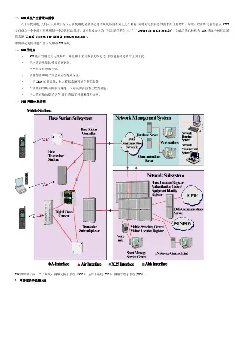
三、GSM 网络体系结构GSM网络被分成三个子系统:网络交换子系统(NSS)、基站子系统(BSS)、网络管理子系统(NMS)。
1、网络交换子系统NSS• 组件: MSC , VLR , HLR , AC, EIR •功能:• 呼叫控制 • 移动性管理• 信令 (对BSS , 其他网络, 其他NSS 组件) • 用户数据处理• 为移动终接呼叫定位用户 •计费2、基站子系统 BSS• 组件: 基站控制器(BSC ),基站收发器(BTS),码型转换器(TC ) •功能:• 无线信道控制,BTS 和TC 控制,用MSC 同步 • Air 和 A 接口信令,MS —NSS 连接确立 • 移动性管理,语音代码转换 •统计数据收集3、网络管理子系统 (NMS/2000 OSS3.1)NMS 的 功 能•故障管理:• 从网络组件收集告警报告 •所有故障情况管理的一个点•配置管理:O &M• 无线网络配置管理•保持关于网络组件状态的数据信息•性能管理:• 从网络组件中收集测量数据 •从原始数据中产生性能结果BSS 系 统 概 述BSS 即Base Station Subsystem —基站子系统; BSS 由BSC 、BTS 、TC (TCSM)组成 一、GSM 网络组成 NSS 、BSS 、OMC/NMS二、BSS 系统中的网元三、GSM 网络中的接口M SPSTN Public Switched Telephone Network PSPDN Packet Switched Public Data Network PLMN Public Land Mobile NetworkCSPDN Circuit-Switched Public Data Network ISDN Integrated Services Digital NetworkBSS 系统中的帧结构1、Abis interface 的帧结构0 1 2 315 16 17 1830 311 2 3 4 5 0 1 21415 16 17 1830 311 2 3 4 564 kbit/s signalling16 kbit/s signallingM SA I / F A t e r I / F A b i s I / FA i r I / F2、D-channel 的结构TS 1234567801TCH.0TCH.1TCH.2TCH.32TCH.4TCH.5TCH.6TCH.73TCH.0TCH.1TCH.2TCH.34TCH.4TCH.5TCH.6TCH.75TCH.0TCH.1TCH.2TCH.36TCH.4TCH.5TCH.6TCH.77TCH.0TCH.1TCH.2TCH.38TCH.4TCH.5TCH.6TCH.79TCH.0TCH.1TCH.2TCH.310TCH.4TCH.5TCH.6TCH.711TCH.0TCH.1TCH.2TCH.312TCH.4TCH.5TCH.6TCH.713TCH.0TCH.1TCH.2TCH.314TCH.4TCH.5TCH.6TCH.715TCH.0TCH.1TCH.2TCH.316TCH.4TCH.5TCH.6TCH.717TCH.0TCH.1TCH.2TCH.318TCH.4TCH.5TCH.6TCH.719TCH.0TCH.1TCH.2TCH.320TCH.4TCH.5TCH.6TCH.721TCH.0TCH.1TCH.2TCH.322TCH.4TCH.5TCH.6TCH.723TCH.0TCH.1TCH.2TCH.324TCH.4TCH.5TCH.6TCH.725TRX1TRX226TRX3TRX427TRX5TRX628TRX7TRX829TRX9TRX1030TRX11TRX1231BCFSIG7、Air interface 的TDMA 帧结构01234567TDMA frame = 8 time slots (120/26 4.615 ms)1 time slot = 156.25 bit durations (15/26 0.577 ms)(1 bit duration 48/13 3.69 us)0123456701234567无 线 信 道 介 绍一、GSM 无线频点范围GSM 900Uplink:890 -915 Mhz Downlink:935 -960 MhzCarrier Pairs (in Mhz)890.0935.0890.2935.2890.4935.4 ........ ........914.8959.8915.0960.0Duplex Frequency = 45 Mhz GSM 1800Uplink:1710 -1785 Mhz Downlink:1805 -1880 MhzCarrier Pairs (in Mhz)1710.01805.01710.21805.21710.41805.4 ........ ........1784.81879.81785.01880.0Duplex Frequency = 95 Mhz 二、逻辑信道1、Broadcast Channels广播信道(BCH)(FCCH)频率校正信道、(SCH)同步信道、(BCCH)广播控制信道2、Common Control Channels公共信道(CCCH)(PCH)寻呼信道、(RACH)随机接入信道、(AGCH)允许接入信道3、Dedicated Channels专用信道(DCH)(SDCCH)独立专用控制信道、(SACCH)慢速随路控制信道(FACCH)快速随路控制信道4、Traffic Channels话务信道(TCH)•Traffic Channel, Full Rate全速率•Traffic Channel,Half Rate半速率三、物理信道与逻辑信道TDMA framePhysical channels TS 0 to TS 7Logical channelsBCH Dedicated ChannelsCCCH FCCH SCH BCCH PCH AGCH RACH DCCH TCHSDCCH SACCH FACCH TCH/F TCH/HTS 2TS 1TS 0TS 7TS 6TS 5TS 4T S 3TS 2TS 1TS 0TS 7T S 6TS 5TS 4TS 3TS 2TS 1TS 0•物理信道:某个频点上的某个时隙• 时隙宽度:0.577ms •频隙宽度:200KHZ• 逻辑信道:根据物理信道中所传内容的不同而分类。

AND M AINTENANCE G UIDEHK1100tention to the following safety guidelines, by any personservicing or operating this tool.1. GlossaryNotes: are reminders of required procedures.Bold, Italic type and underlining: emphasizes a specific in-struction.2. A half hour long hands-on training session with quali-fied personnel is recommended before using Huckequipment.3. Huck equipment must be maintained in a safe workingcondition at all times. T ools and hoses should be in-spected at the beginning of each shift/day for damageor wear. Any repair should be done by a qualified re-pairman trained on Huck procedures.4.Repairman and Operator must read manual prior tousing equipment. Warning and Caution stickers/labelssupplied with equipment must be understood beforeconnecting equipment to any primary power supply.As applicable, each of the sections in this manualhave specific safety and other information.5.Read MSDS Specifications before servicing the tool.MSDS Specifications are available from the productmanufacturer or your Huck representative.6.When repairing or operating Huck installation equip-ment, always wear approved eye protection. Whereapplicable, refer to ANSI Z87.1 - 20037.Disconnect primary power source before performingmaintenance on Huck equipment or changing NoseAssembly.8.T ools and hoses should be inspected for leaks at thebeginning of each shift/day. If any equipment showssigns of damage, wear, or leakage, do not connect itto the primary power supply.9.Mounting hardware should be checked at the begin-ning of each shift/day.10.Make sure proper power source is used at all times.12.T ools are not to be used in an explosive environmentunless specifically designed to do so.13.Never remove any safety guards or pintail deflectors.14.Where applicable, ensure deflector or pintail collectoris installed and operating prior to use.15.Never install a fastener in free air. Personal injury fromfastener ejecting may occur.16.Where applicable, always clear spent pintail out ofnose assembly before installing the next fastener.17.There is possibility of forcible ejection of pintails orspent mandrels from front of tool.18.If there is a pinch point between trigger and workpiece, use remote trigger when possible.19.Unsuitable postures may not allow counteracting ofnormal expected movement of tool.20.Do not abuse tool by dropping or using it as a ham-mer. Never use hydraulic or air lines as a handle or tobend or pry the tool. Reasonable care of installationtools by operators is an important factor in maintainingtool efficiency, eliminating downtime, and in prevent-ing an accident which may cause severe personal in-jury.21.Never place hands between nose assembly and workpiece. Keep hands clear from front of tool. Neverplace hands near moving parts.22.There is a risk of crushing if tool is cycled withoutNose Assembly installed.23.T ools with ejector rods should never be cycled without nose assembly installed.24.When two piece lock bolts are being used alwaysmake sure the collar orientation is correct. See fas-tener data sheet of correct positioning.25.T ool is only to be used as stated in this manual. Anyother use is prohibited.26.There is a risk of whipping compressed air hose if toolis pneudraulic or pneumatic.27.Release the trigger in case of failure of air supply orhydraulic supply.e only fluids or lubricants recommended.29.Disposal instruction: Disassemble and recycle steel,aluminum and plastic parts, and drain and dispose ofhydraulic fluid in accordance with local lawful and safepractices.30.If tool is fixed to a suspension device, ensure that thedevice is secure prior to operating the tool.WARNINGS: Must be understood toavoid severe personal injury.CAUTIONS: show conditions that willdamage equipment and or structure.Product complies with requirements set forth bythe relevant European directives.Read manual prior to using this equipment.Eye protection is required while using thisequipment.Hearing protection is required while using thisequipment.N OSE A SSEMBLY I NSTRUCTIONS1.P REPARE TOOL PER MANUAL :Discon-nect Powerig’s power source. Con-nect tool’s hoses and controls toPowerig. Reconnect power source.Press trigger for 30 seconds; pistonstops when completely forward. Dis-connect controls and RETURN pres-sure hose. Tool piston must remaincompletely forward.2.D ISASSEMBL Y /A SSEMBL Y AS APPLIES :Remove parts of Nose Assembly forinspection and maintenance.Anvil:Pressed in Anvil insert is pressed outwith drift and an arbor press. Pressnew insert in squarely to preventcracking.Collet and Drawbar:Assemble Collet as shown in theNose Assembly drawing supplied withthe Nose Assembly. Slide Drawbarinto Collet. Push crosspin throughCollet and Drawbar. With Loctite ®onthreads, lock Collet to Drawbar withtightly installed socket head screw.3.A TTACHING TO TOOL :3.1 CROSS PIN STYLE:While holding front of Collet againstback of Anvil, screw assembly ontotool (Figure 1), ensuring that allguarding is installed on the Nose As-sembly (Figure 2).3.2 FRONT BEARING STYLE:While holding front of Collet against back of Anvil, screw Anvil onto tool (Figure3). S crew the Drawbar into the tool (Figure 4).If necessary, place Shim p/n 128290between the Collet and tool Piston (Figures 5 & 7). Make sure that all guarding is installed on the Nose As-sembly (Figure 6).4.C HECKING N OSE A SSEMBL Y :See WARNING. Connect controls and RETURN pressure hose. Recon-nect Powerig to power source. Install fasteners in test plate of correct thick-ness with proper size holes, and in-spect fasteners.NOTE: To extend jaw life, disassem-ble Nose Assembly periodically and clean and inspect components,using a pick to clean jaw grooves.Dry O-Rings and urethane jaw as-semblies immediately after cleaning,as prolonged contact with solvent causes swelling. Dry other parts.WARNING: Before performingmaintenance or adjustments,Powerig® hydraulic unit mustbe disconnected fromelectrical or air supply.If not disconnected, severepersonal injury and / ordamage may result.CAUTION: Wash parts in mineral spirits or isopropyl alcohol only.Figure 2 Figure 3Figure 5Figure 6SHIM Insert and Screw DrawbarA Global OrganizationAlcoa Fastening Systems (AFS) maintains com-pany offices throughout the United States andCanada, with subsidiary offices in many othercountries. Authorized AFS distributors are also located in many of the world’s Industrial and Aerospace centers, where they provide a ready source of AFS fasteners, installation tools, tool parts, and application assistance.For The Long Haul, The Future of Fastening Technology, The Future of AssemblyTechnology, The Future of Tooling Technology, and Tools of Productivity are servicemarks of Huck International. Huck provides technical assistance regarding the useand application of Huck fasteners and tooling.NOTICE: The information contained in this publication is only for general guidancewith regard to properties of the products shown and/or the means for selectingsuch products, and is not intended to create any warranty, express, implied, orstatutory; all warranties are contained only in Huck’s written quotations, acknowl‐edgements, and/or purchase orders. It is recommended that the user secure spe‐cific, up‐to‐date data and information regarding each application and/or use ofsuch products.HWB898 1003‐5M © 2003 Alcoa Fastening Systems1 Corporate Drive, Kingston, NY 12401 • Tel: 800‐431‐3091 • Fax: 845‐334‐7333 • One Great Connection SM。


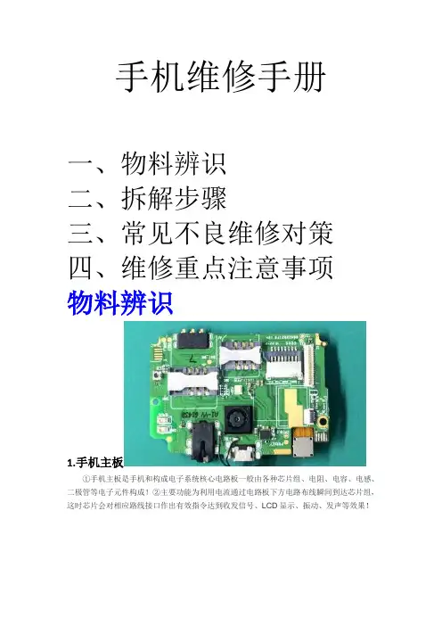
手机维修手册一、物料辨识二、拆解步骤三、常见不良维修对策四、维修重点注意事项物料辨识1.手机主板①手机主板是手机和构成电子系统核心电路板一般由各种芯片组、电阻、电容、电感、二极管等电子元件构成!②主要功能为利用电流通过电路板下方电路布线瞬间到达芯片组,这时芯片会对相应路线接口作出有效指令达到收发信号、LCD显示、振动、发声等效果!2.触摸屏触摸屏又称为触控屏、触控面板,是一种可接收触头等输入讯号的感应式液晶显示装置,当接触了屏幕上的图形按钮时,屏幕上的触觉反馈系统可根据预先编程的程式驱动各种连结装置,一般手机触摸屏材质为电容式触摸屏!3.LCD(显示屏)液晶显示器的构造是在两片平行的玻璃基板当中放置液晶盒,下基板玻璃上设置(薄膜晶体管),上基板玻璃上设置彩色滤光片,通过TFT上的信号与电压改变来控制液晶分子的转动方向,从而达到控制每个像素点偏振光出射与否而达到显示目的。
4.电池手机电池是为手机提供电力的储能工具,手机电池一般用的是锂电池和镍氢电池。
“mAh”是电池容量的单位,中文名称是毫安时。
5.摄像头手机摄像头分为内置与外置,内置摄像头是指摄像头在手机内部,更方便。
外置手机通过数据线或者手机下部接口与数码相机相连,来完成数码相机的一切拍摄功能。
一般后像素在1200W、1600W、2000W,前摄在500W和800W6.喇叭(扬声器)扬声器的原理是电流通过由磁铁组成的磁电路内的线圈,在上和下的方向上产生驱动力使振动体振动,继而使空气振动,发出声音。
7.按键FPC按键排线是连接板段接口和按键感应的重要料件,主要负责感应和传达开关机,音量加减等直接作用!拆解步骤以HR5081拆解流程为例:1:拆电池盖(从电池盖拆机扣位处,往上轻轻拉开电池盖,指甲依次划过电池盖与底壳交接处)2:拆电池(从副板电池拆解处,往上轻轻取下电池,电池要有专门的盒子分开放置)3:取底壳螺丝(依次取下底壳13颗螺丝放到螺丝盘里)4:拆底壳(取下底壳注意按键板处不能用力扯已免损伤排线)5:取主板螺丝、副班螺丝(依次取下板上3颗螺丝放到螺丝盘里)6:拆LCD、TP、按键板排线(注意轻拿轻放已免损伤排线)7:拆主板拆射频线(注意不要拉扯到听筒线,射频线要在主板抬起后取下)8:拆按键板9:拆听筒10:前后摄像头11:拆副板(副板下有双面胶固定,拆解不能用蛮力已免副板变形)12:拆麦克、马达13:拆喇叭、光感套(拆解喇叭要用酒精已免损伤喇叭)14:加热拆解TP、LCD组合屏(加热温度80以下,加热时间不能多于80秒)15:分离TP、LCD常见不良维修对策维修重点注意事项1:LCD、TP粘合拆解,加热台温度不可高于80度,加热时间不多余80秒(温度过高时间过久LCD会膜邹)2:副板加工麦克、马达温度不应高于340度(因材质问题,温度过高极易掉铜皮) 3:LCD、TP、副板FPC排线金手指极易有胶(应TP、LCD粘合有多余胶粘到排线金手指)4:拆解过程极易拉扯损坏TP排线、按键板排线请注意手法(因排线类都有双面胶固定且排线较短)5:射频线固定扣位来料有变形请注意纠正已免(会导致射频线磨损破裂)。

BinocularsService and RepairIf warranty problems arise or repairs are necessary, contact the STYRKA customer service departmentat 1-844-211-6915. We promise prompt attention and service, as we understand the importance of optics to yourhunting experience. And, we take pride in providing not only outstanding products, but excellent service as well.WarrantyIt’s all about the experience! At STYRKA, we strive to make sure your experience in the fi eld is a great one.And we stand behind our products to do just that.That’s why the STYRKA Pride Warranty is so simple. In the event of damage or malfunction, we will repair orreplace your STYRKA product free of charge. No questions asked. No registration required. No receipt needed.No matter who bought it. The only caveat? The warranty doesn’t cover theft, loss or intentional damage.It gets better. Send us your STYRKA product and we’ll clean and tune it up once per year. Regular maintenancehelps keep your STYRKA performing like the day you bought it.Again, it’s all about the experience, and we want yours with STYRKA to be the best.S7SERIES BinocularsSTYRKA S7 Series Binoculars Thank you for purchasing your STYRKA S7 Binocular. We are certain this binocularwill provide you with years of enjoyment andfaithful service in the fi eld. Please read the instructions carefully before using your binocular to ensure proper use and care.WARNING: Never look at the sun while using yourbinocular. Looking at the sun can cause permanent eye damage.Adjusting the Interpupillary DistanceThe interpupillary distance, the distance between pupils, varies from person to person. The binocular must be correctly aligned (adjusted) to the distance between your pupils to achieve a single, clear image. T o adjust this distance, lift the binocular up to your eyes (using both hands) and look through them at a distant object. Move the two barrels (halves) of the binocular closer together or further apart until you see a single, clear image. Check that the interpupillary distance is set correctly every time you use your binocular.Rainguard (not shown)Objective Lens Cap (not shown)Neck Strap (not shown)Case (not shown)Fig. 1DiopterAdjustmentRing FocusWheelEyecupEyepieceObjectiveLens Logo Plate /Tripod Adapter Thread Fig. 2Setting the Diopter / FocusingT o ensure a crisp, sharp image the focusing systemof the binocular must be set to compensate for any differences in your eyesight. This is achieved by setting the diopter (located on the right eyepiece) before use. T o set the binocular to your eyesight follow the instructions below.1.View an object in the distance through the binocular.2.Cover the right objective lens with your hand or theobjective lens cap.3.Rotate the focus wheel until the image viewed withyour left eye is clear and sharp.4.Cover the left objective lens with your hand orobjective lens cap.5.Viewing the same object, adjust the diopter ringuntil the image viewed with your right eye is clear and sharp.Eyecup AdjustmentThe STYRKA S7 Series features twist-up eyecupsto accommodate both eyeglass and non-eyeglasswearers. If you do not wear eyeglasses, twist theeyecups counterclockwise until they reach the upposition. If you wear eyeglasses, make sure thatthe eyecups are in the down position to obtain themaximum fi eld of view. The eyecups can be set atpositions between fully up and down which maybetter suit some users.6.Your binocular is now adjusted to your eyes andfocusing on any object can now be achieved bysimply turning the focus wheel.Tip:Eyeglasses worn for nearsightedness should be worn when usingbinoculars as you may not be able to obtain focus at infi nity without them.Fig. 3DiopterAdjustmentRing FocusWheelFig. 4Tripod AdaptabilitySTYRKA S7 Series binoculars feature built-in threads that allow the binocular to be attached to a tripod using a binocular tripod adapter. These threads can be accessed by unscrewing the logo plate found on the front of the hinge. T o attach the binocular to a tripod, thread the adapter into the binocular and attach the other end of the adapter to a photographic tripod. Mounting the binocular on a tripod allows for added stability and comfort during prolonged viewing. Care and StorageYour STYRKA binocular will provide you years of dependable service in the fi eld if it is cared forand stored properly.5.Do not leave the binocular in a car on a hot/sunny day or near anything that generates heatas this may cause damage.6.Clean any dust, dirt or water that may get onthe binocular or inside moving parts as soonas possible to prevent any unforeseen damage.1.Protect the binocular from impact and do notforce any of the moving parts beyond their limits.2.Protect the optics of your binocular by puttingon all lens caps when not in use.3.Store your binocular in a cool, dry placewhenever possible.4.When storing for an extended period of time,place the binocular in a plastic bag or airtightcontainer with a desiccant.Waterproof / FogproofSTYRKA S7 Series binoculars are waterproof and fi lled with dry nitrogen gas to prevent the housing from fogging internally. This allows the binoculars to be used in all weather conditions.Fig. 5CleaningProper cleaning of the lenses is essential to maintaining the optical integrity of your binocular. Dirty lenses diminish the amount of light transmitted through the binocular and your overall viewing experience.1.Remove any dust on the lenses with a soft lens brush or canof pressurized air.ing the Spudz microfi ber cleaning cloth (included) removeany fi ngerprints, stains or smudges from the lens surface byrubbing in a circular motion. Start in the middle of the lens andwork your way to the edges. Breathe lightly on the lens to provide moisture if needed.3.For a more thorough cleaning we recommend the use of a lens/optics cleaning kit available at most photo or optical shops.Follow the directions supplied with the cleaning kit for best results.Specifi cations8x30 8x42 10x42Magnifi cation8x 8x 10xObjective Lens Diameter30mm 42mm 42mmAngular Field of View8.3˚ 7.8˚ 6.5˚Linear Field of View @ 1000yds436ft 409ft 341ftExit Pupil 3.75mm 5.25mm 4.2mmEye Relief 15.1mm18mm17mmClose Focus8.2ft 6.5ft 6.5ftRelative Brightness14.1 27.5 17.6Twilight Factor15.5 18.3 20.5Product design and specifi cations are subject to change without prior notifi cation.For complete specifi cations and product information, visit: 1284 Corporate Center Drive, Suite 175, Eagan, MN 55121 USAT el: 651.330.1505。
基础心得供电及开关机原理:(以摩拉A780为例)电池接口加电获得B+(即BA TT+:3.6V),按下开机键后立刻将电源IC某一个脚的电平拉低启动电源IC工作,电源IC得到B+后,马上启动32.768KHz实时时钟,在电源IC内部整形后再送出,接着送给CPU,所以32.768KHz实时时钟损坏也会导致手机不开机。
26MHz 主时钟得到供电后,马上从脚送出26MHz时钟,接着兵分两路:一路作为参考频率送给中频IC,若不正常,会导致手机无信号;另一路作为主时钟送给CPU,若不正常会导致手机不开机。
另外26MHz时钟也会在CPU内部二分频得到13MHz送给电源IC。
复位电路:由电源IC送出系统复位信号,送给CPU,若无,手机不开机;再由CPU送给版本,若无手机不开机。
CPU得到供电、时钟及复位后,马上从版本IC内部调用并运行开机程序,一旦通过后再从CPU的U13送出一个电压约为2.775V的WDOG开机维持给电源IC的12脚,维持各路供电的输出,最终完成开机过程。
1、听筒:也叫受话器、扬声器。
常用字母SPK或SPEAKER及EAR和EARPHONE表示。
检测方法:法一:一般听筒有一个直流电阻,阻值通常在几十欧,如果直流电阻明显变得很小或很大,则需要更换听筒。
法二:用1.5V电压轻触听筒两极,能发出“嚓嚓”声,说明听筒好,否则损坏。
也可以用示波器检测:如受话器好,则能够用示波器没到受话器触点的波形(要同时拨打112);若没有波开,则进一步检查音频解码电路和CPU。
查到哪一级若有输入信号而没有输出信号,则说明该级电路不良。
若受话噪声大,则则大多为受话器接触不良或进话电路虚焊或损坏。
2、振铃器:也叫蜂鸣器,是一个动圈式小喇叭。
电阻在十几欧到几千欧。
用字母BUZZ表示。
手机的按键音很多是由振铃发出的,而不要错误地认为手机的按键音全是由听筒发出的。
在维修“听不到对方讲话”故障(听筒电路有问题)时,发现手机有音,以为是听筒发出的声音,感到比较疑惑,其原因是没有弄清按键到底从何来。
废话少说..直接进主题..`[本帖最后由 672522080 于 2008-1-10 16:22 编辑] 附件下载:1110-1600振铃和听筒连线.JPG[下载次数:51]下载:1600无铃声和听筒音.用免提可以打电话短接AB点.jpg[下载次数:45]下载:2650卡电路的连接图.jpg[下载次数:32]下载:3230手机无显示.jpg[下载次数:40]下载:5300内存卡IC短接.jpg[下载次数:40]下载:3230无灯.jpg[下载次数:41]下载:6020.7260不照相.jpg[下载次数:42]下载:3250照相出现此功能不被支持解决方法.jpg[下载次数:39]下载:6020不送话.jpg[下载次数:40]下载:6111无铃声.jpg[下载次数:39]下载:6270进水不能照相必杀.jpg[下载次数:38]下载:6270无送话,玻璃管损坏的飞线解决的方法.jpg[下载次数:34]下载:7260显示屏一闪一闪的维修.jpg[下载次数:35]下载:7260灯控原理图.jpg[下载次数:30]下载:7370 解决出现未能充电.jpg[下载次数:40]下载:7610按键组成以及管脚.jpg[下载次数:32]下载:7610不识MMC卡.jpg[下载次数:32] 下载:BB5手机 IC 型号.JPG[下载次数:28]下载:7610开机白屏,可打电话,可关机.jpg[下载次数:32]下载:BB5天线开关飞线图.jpg[下载次数:33]下载:7610开机白屏十秒钟左右关机的维修方法,针对刷机故障依旧者.jpg[下载次数:28]下载:BB5天线开关接线图.jpg[下载次数:30]下载:8800耳机和车载模式必杀!!!.jpg[下载次数:39]下载:N70_72显示芯片故障判断.jpg[下载次数:41]。