大众标准TL 217中文 2009年8月版
- 格式:docx
- 大小:26.52 KB
- 文档页数:7
大众汽车集团标准 TL 2442010年12月版分类号:50223关键字:锌,镍,钝化处理,密封,无Cr(VI),防腐蚀,表面保护锌/镍-合金涂覆层表面保护要求旧版本TL 244: 1987-10, 1992-05, 1993-11, 1995-12, 2002-05, 2004-12, 2006-08, 2007-02变更相对于 TL244: 2007-02 版本,作了如下更改:--补充了热处理后零件的抗拉强度≦ 1200Mpa 部分;--添加了 Ofl-r647 和 Ofl-r648 两种涂覆方法;--原表 2 中关于含铬的表面保护类型已删除;--添加了图 1 和图 2;--添加了 PV 1209,PV 1200 和 PV1210 三种测试依据;--镀层表面形态的要求有所增加;--镍的上限值有所改变;--原第 4 条关于镀层厚度的测量的内容加入到 3.9 部分;--原 3.11 部分的要求有所改变;--参考标准有更新;--标准重组。
1 范围本标准规定了抗拉强度为 Rm≦ 1000Mpa(按 VW 137 50 的特征字母 r)的铁材料和钢制件上的电解离析和无Cr( VI)后处理的锌/镍合金涂覆层的要求。
此外还定义了抗拉强度值大于 1000Mpa时的应用极限。
本标准定义了合金涂覆不适用于抗拉强度 Rm>1200Mpa 和表面硬度>370HV 的钢制件。
而且适用于抗拉强度值在 1000Mpa 和 1200Mpa之间的钢制件时,必须按 DIN EN ISO 4042 作热处理。
这些当作坚固防腐层(稳定等级为 6)的涂覆层,亦特别适用于除了腐蚀负荷增加和温度负荷增加至150°C(例如:发动机室和刹车系统)之外的部件以及螺栓拧紧系统。
银色涂覆层(例如:Ofl-r642,Ofl-r643,Ofl-r645和Ofl-r647)特别适用于导线连接(接地线连接)。
这些涂覆层特别适用于内部传动的紧固元件,以避免附加的施力作用。
Infotainment SystemsGeneral Functional RequirementsPrefaceToday, specific performance specifications are available for all new infotainment projects, defining requirements on a project-specific basis. In order to avoid confusion and ambiguity, these require‐ments will be removed from this standard (in compliance with the CC Radio/Tuner decision of January 14, 2008) which will be limited to more general issues. Only the methods and measurement proce‐dures used to determine the characteristic values of the specific requirements will be described.Previous issuesTL 972: 1995-07; VW 80972: 2000-07, 2001-10, 2006-09ChangesThe following changes have been made as compared to VW 80972: 2006-09:–Title changed–Scope: extended to include all infotainment systems–Release testing: extended and divided into field testing and laboratory testing with references tospecific performance specifications –Definitions: supplemented–Editorial: Replacement of term LF (low frequency) by audio operating modes and descriptionaccording to definiton in VW 80101–Environmental requirements supplemented–Preferred measurement frequency: AM harmonized for NAR and EU–Temperature requirements: Section 8.2.1.1 Audio continuous power, system cooling divided into5.2.3.1 System cooling and 8.2.1.1 Audio continuous power; further installation locations andcontrol elements added and temperature stages test addedGroup StandardVW 80972Issue 2009-11Class. No.:8FL40Descriptors:car radio, radio, radio navigation systems, infotainment modules, infotainment, audio systems, mediaCheck standard for current issue prior to usage.This electronically generated standard is authentic and valid without signature.The English translation is believed to be accurate. In case of discrepancies the German version shall govern.Numerical notation acc. to ISO practice.Page 1 of 39Technical responsibility Standards Department EEFI/3Detlev BeyerTel.: +49-5361-9-23881EKDV/4 Dirk Beinker EKDVTel.: +49-5361-9-32438Manfred TerlindenConfidential. All rights reserved. No part of this document may be transmitted or reproduced without prior permission of a Standards Department of the Volkswagen Group.Parties to a contract can only obtain this standard via the B2B supplier platform .© Volkswagen AktiengesellschaftVWNORM-2008-12hPage 2VW 80972: 2009-11–EMC approval: Individual standards removed and reference to Volkswagen Component Perfor‐mance Specifications Template for EMC module added–Illumination: Reference to Performance Specifications on Illumination (of Display and Control Elements in the Passenger Compartment) added–Antenna remote supply: AM/FM harmonized with DAB, SDARS complemented–Operating temperatures: CompactCassette (CC) and MiniDisk (MD) withdrawn–Operating noise: CC and MD withdrawn, DVD added–Test sequence: Table 3 updated–Mechanics requirements: Reference to …MIB_Device_Mechanics_Main_Unit“, Chapter 4 "Tech‐nical Requirements"; load cycle quantity deleted–Actuation forces: keys, values revised–Endurance test: Output power increased and radio extended to 1000 h–Voltages: Functional states, editorial revision, supplements and revision of "after end of functional state D"–Voltage dip: requirements complemented–Interruption: conditions after functional state added–Interference immunity: operating voltages quickly changing in time added–Switching behavior, ON/OFF: reference to MIB power management performance specifications added–Control input/output: MOST reference added to CAN performance specifications–Audio requirements: Reference to performance specifications …MIB_RQ_List_Sound“ added and note on common mode rejection for voltage changes added–Audio phase position AM/FM new–Common mode rejection: values revised–Audio source level plan: generalized, only refers to basic sources–BOSE®: deleted–Other sound systems: new description: sound systems, "branded"–Audio outputs: Values adapted–Frequency responses: Measurement conditions for different sources combined and reference to performance specifications "MIB_RQ_List_Sound" added–Control capacity of ...: merged and reference to performance specifications "MIB_RQ_List_Sound" added–Audio inputs: values adapted–CC drive requirements: removed–MD drive requirements: removed–CD, DVD audio,...: combined in the media Section and reference to performance specifications added–CD, DVD, HDD drive requirements revised with regard to mechanics and performance require‐ments described in VDA guideline 240-300 and in the "Test Case Book for Automotive Drives".–Video requirements: new–Navigation requirements new–Road test: text on assessment revised–Table 1: deleted, integrated in radio sections–Laboratory testing: operating noise and rattling added– 5.1.2 Operating temperatures: text complemented– 5.3.4 System temperature management : Text complemented– 5.5 Illumination: only reference to: display illumination performance specifications– 5.7 Chemical requirements: listing of individual substances omitted, only reference to VW 80101,a), o) and q) deleted– 5.11 Operating noise: details complemented– 6. Mechanical Requirements: All individual points deleted, only reference to performance spe‐cifications, VW80101 and performance specifications module "Testing"– 5. General requirements: Reference to other requirement areas according to VW 80101– 5.1.2 Temperature requirements complemented– 5.7 Resistance to light complemented, distinction of materials– 5.8 Test sequence: table removed, reference to MQB test performance specifications– 5.10 Operating noise: reference to VW 82469, "Accessory Equipment; Acoustic Requirements"–7.1 Adjustable frequency ranges: table removed and references created –7.2 Voltages: adapted to new values from AK 4.14–7.8 Irritating noise: control elements reintegrated and headline errors revised –12. Telephone requirements: reference to performance specifications–13. Radio requirements: reference to performance specifications and radio sections of this stan‐dard–New limit values more suitable for practical use for: 8.2.6 THD against power; 8.7 Audio inputs S/N; 9.3.1.3 Channel separation –EMC references revised–Audio requirements: changed name of performance specifications adopted –7.4.2.3 Antenna supply: current limitation added–8.5 Reception-quality-dependent sound influence: deleted, reference to "MIB_RQ_Radio_AM-FM-IBOC"ContentsPageScope .............................................................................................................................5Terms .............................................................................................................................6General descriptions: .....................................................................................................6Broadcasting terms for radio wave ranges depending on wave length .........................6Higher-level regulations and guidelines .........................................................................7Regulations ....................................................................................................................7Applicable laws and regulations .....................................................................................7EMC approval ................................................................................................................8Environmental requirements ..........................................................................................8General test conditions ..................................................................................................8Voltage source ...............................................................................................................8Test temperature ............................................................................................................9Preferred measurement frequencies .............................................................................9Modulation .....................................................................................................................9Note .............................................................................................................................10Identification of devices ................................................................................................10Test frames (schematic description) . (10)122.12.233.13.23.33.444.14.24.34.44.54.64.7Page 3VW 80972: 2009-11Operating modes (extract from VW 80101, Operating modes) ....................................10General requirements ..................................................................................................11Release testing ............................................................................................................11Road test ......................................................................................................................11Laboratory testing ........................................................................................................12Temperature requirements ..........................................................................................12Operating temperatures ...............................................................................................13Multi-stage temperature test ........................................................................................13Temperature resistance ..............................................................................................13Conditioning (forced-air aging, without load) ...............................................................13Temperature cycle (no load) ........................................................................................14Rapid temperature cycle with specified transfer duration (thermal shock test) ............14System temperature management ...............................................................................14Resistance to humid/warm environments (cyclic) ........................................................15Illumination/nighttime design ........................................................................................16Control elements (buttons and trim) .............................................................................16Chemical requirements (resistance to chemical agents) .............................................16Lightfastness ................................................................................................................16Test sequence .............................................................................................................16Flammability .................................................................................................................16Operating noise ............................................................................................................16Noise limit values during excitation (rattling and squeaking) .......................................17Mechanical requirements .............................................................................................17Requirements for electric system .................................................................................17Frequency ranges that can be selected .......................................................................17Voltages .......................................................................................................................18Overvoltage strength ....................................................................................................19Testing at 10,8 V ..........................................................................................................19Voltage dip, brief period (starting pulse) ......................................................................19Interruption ...................................................................................................................19Reverse polarity protection ..........................................................................................20Current .........................................................................................................................20Maximum permissible closed-circuit current/power consumption ................................20Control lines (capacity) ................................................................................................20Overcurrent strength ....................................................................................................22Switching behavior, ON/OFF .......................................................................................22Control inputs ...............................................................................................................22PHONE (analog input) .................................................................................................22S contact (analog input) ...............................................................................................22Illumination ...................................................................................................................23Speed-dependent volume control ................................................................................23Frequency constancy ...................................................................................................23Station frequency repeatability .....................................................................................23Frequency drift upon change in ambient temperature .................................................23Frequency drift upon changes in operating voltage .....................................................24Interferences ................................................................................................................24Interferences caused by control elements ...................................................................24Interference caused by internally generated auxiliary operating frequencies orcheck routines ..............................................................................................................24Interference due to internal drives (CD, DVD, SD and HDD) ......................................25Interference immunity ..................................................................................................25Ignition interference .. (25)4.855.15.1.15.1.25.25.2.15.2.25.35.3.15.3.25.3.35.3.45.45.55.65.75.85.95.105.115.12677.17.27.37.3.17.3.27.3.37.3.47.47.4.17.4.27.4.37.57.67.6.17.6.27.6.37.6.47.77.7.17.7.27.7.37.87.8.17.8.27.8.37.97.9.1Page 4VW 80972: 2009-11Electric system interference .........................................................................................25Interference caused by alternator ................................................................................25Electrostatic charging protection ..................................................................................26Audio requirements ......................................................................................................26Audio source level plan (objective: lowest possible subjective volume difference)......................................................................................................................................26Audio outputs ...............................................................................................................27Audio outputs for passive speaker systems .................................................................27Audio outputs for sound systems (line/AUX out, rear seat entertainment) ..................28Audio outputs for sound systems with full level input ...................................................29Audio background noise ..............................................................................................29Clipping ........................................................................................................................29THD against power ......................................................................................................29Volume range ...............................................................................................................30Audio phase position at FM and AM ............................................................................30Audio frequency response ..........................................................................................30Loudness .....................................................................................................................31Vehicle-specific sound curve, frequency response for traffic audio memory ...............31Control capacity of the volume, geometry and bass/treble controls ............................31Reception-quality-dependent sound influence for FM .................................................31Speed-dependent corrections of the audio signal ........................................................31Audio inputs .................................................................................................................31Stereo input for external media ....................................................................................31Stereo input for external media (AUX) .........................................................................32Audio input for telephone .............................................................................................32Media AUDIO requirements .........................................................................................32Cassette operation, cassette drive requirements .........................................................32MiniDisc operation (MD requirements) ........................................................................32CD, DVD, HDD and SD operation ...............................................................................32CD playback requirements ...........................................................................................33Memory cards ..............................................................................................................34Hard disk drives (HDD) as audio source ......................................................................36Video requirements ......................................................................................................37TV requirements ..........................................................................................................37Navigation requirements ..............................................................................................37Telephone requirements ..............................................................................................37Radio requirements ......................................................................................................37Radio requirements EUROPA, CHINA and ROW .......................................................38Radio requirements, JAPAN ........................................................................................38Radio requirements North America / Latin America .....................................................38Referenced documents ................................................................................................38Bibliography .................................................................................................................397.9.27.9.37.1088.18.28.2.18.2.28.2.38.2.48.2.58.2.68.2.78.2.88.38.3.18.3.28.48.58.68.78.7.18.7.28.7.399.19.29.39.3.19.3.29.3.31010.111121313.113.213.31415ScopeThis standard specifies requirements and tests for all infotainment systems implemented within the Volkswagen Group and associated components (radios, navigation systems, media player, audio amplifiers,...).The relevant version valid at the time the order is placed applies to corresponding standards and regulations.1Page 5VW 80972: 2009-11The performance specifications (German abbreviation LAH) specified in this standard are exemplary and must be specifically adapted for other projects. The compliance with the respective component performance specifications (German abbreviation BT-LAH) and with this standard are prerequisites for technical engineering approval (BMG) and the resulting component release.TermsGeneral descriptions:AU-S Function description AU dio S ound OMO perating M odeControl elementsAll elements (keys, knobs, display and media) which must be used for oper‐ation, use or control of the systemUser-accessible areas All areas that can be touched voluntarily or involuntarily by the user withoutremoving installation, add-on, trim or protection elementsBMG Technical Engineering Approval (German abbreviation)BT-LAH Component Performance Specifications (German abbreviation)CRIN Description in ISO for C ar R adio I dentification N umber HW H ard W are LCD L iquid C rystal D isplay (display type)LSM L ast S ituation M emory ROW "R est o f W orld", applies to requirements not assigned to specific regions RT R oom T emperature SW S oft W are TFT T hin F ilm T ransistor (display type)Calibration value Measured value in as-delivered condition before carrying out any test thatmay have an influenceHead impact Simulation of a collision in which the front seat passengers' heads hit thedashboard.KAF Volkswagen group acceptance test drive (German abbreviation)Functional statuses See VW 80101, Section on functional states Broadcasting terms for radio wave ranges depending on wave lengthAMA mplitude M odulation, also MFLimitation Compensation of audio level fluctuations depending on the reception level DAB Digital Audio Broadcasting (digital radio)dB Unit of measure for the logarithmic relationship of levels dBµV Logarithmic level relationship with the reference value 1µVE´RF level at antenna input downstream of the antenna simulation E´R RF level for noise-limited sensitivity f N Frequency of the desired station f S Frequency of the interfering stationf nnth transmitter in multiple-transmitter measuring methods2 2.12.2 Page 6VW 80972: 2009-11FM F requency M odulation, also VHF VHF V ery H igh F requency, also FMFS "F ull S cale" reference full level CD 0 dB (full modulation amplitude)RF R adio F requency, frequencies > 100 kHz k maxMaximum nonlinear distortion factorNonlinear distortion factor Degree of nonlinear audio distortions, indicated in %SW S hort W aveL Left stereo channel LW L ong W avem Modulation level for AM modulations in %MW M edium W ave, also AMLFL ow F requency, audio frequency range, 20 Hz to 20 kHz Desired station Station tuned in to listen to P LFAudio output powerRRight stereo channelStereo2-channel sound playbackInterfering station The station influencing the desired station T HS Temperature on heat sinkT CE Temperature of trim/control elementsU B Battery voltage/operating voltage at the control unit's connection block U Ant Antenna operating voltage at the antenna jackU A RF output level at signal generator upstream of antenna simulation Δf Modulation shift for FM modulations in kHzHigher-level regulations and guidelines RegulationsUnless other requirements exist, the standard production devices must comply with the specifications of the respective national governmental approval agency.The manufacturer is responsible for proof of compliance.Applicable laws and regulationsPassenger compartment (interior trim)ECE R21 [1]Passenger compartment (head impact)EC 74/60 EEC [2]Electromagnetic compatibility ECE R101) [3]Electromagnetic compatibilityEC GL 2006/96/EC [4]Presentation for type approval for the passenger compartment specifications to the releasing gov‐ernment authority is carried out and released by the responsible department of the respective cor‐porate brand in the scope of the vehicle type approval process.3 3.13.21)This is covered by the Volkswagen Group in the EMC type approval. For the original equipment, use in the vehicle manufacturing plant,neither an e nor an E nor a CE marking is required.Page 7VW 80972: 2009-11EMC approvalFor original use, an EMC approval is carried out by the Volkswagen AG specialized departments in the scope of the vehicle type approval process.Compliance with the applicable EMC guidelines according to "VW Component Performance Specifi‐cations Template Module for EMC" [5] is absolutely necessary for this.For EMC testing, all sample versions starting from the basic sample must be submitted to the re‐sponsible department including complete documentation and measurement protocols. For EMC re‐lease, three sample devices representing the standard production status have to be presented. After successful release, these devices must be stored as confirmed reference samples, one device at the department carrying out the EMC release, one at the development release department and one at the manufacturer.Environmental requirementsCompliance with the Group requirements for the manufacture of the devices and the choice of the materials must be ensured.–VW 91100 "Environmental Standard for Vehicles; Vehicle Parts, Materials, Operating Fluids;Policy, Specifications"–VW 91101 "Environmental Standard for Vehicles Vehicle Parts, Materials, Operating Fluids Avoidance of Hazardous Substances"–VW 91102 SUPPLEMENT 3 "Environmental Standard for Vehicles;Requirements for a Process‐ing Concept"–VW 91102 "Environmental Standard for Vehicles; Recycling Requirements, Use of Recycled Material, Type Approval with Regard to Recyclability"–VW 91104 "Vehicle Environmental Standard; Basics, Technical Inventory Analysis, Life Cycle Inventory Analysis"–VDA 260 "Motor Vehicle Components; Marking of Materials"Compliance must be documented by the manufacturer by means of a hazardous-substance docu‐mentation list including quantity data for the hazardous substances contained in the product.General test conditionsAll DUTs must comply with the requirements specified in VW 80101. All parts must completely fulfill their specified function both during and after the tests, unless these are destructive tests. The re‐quirements apply to the entire operating voltage and operating temperature ranges.During the tests, the DUTs must be continuously monitored using suitable monitoring devices with test cycles adapted to the requirements and the operating states.For test procedure, number and sequence, see test performance specifications. See also Section 5.9 for further notes.Voltage sourceTest voltage14V ± 0,1 V, terminal voltage at the device Internal resistance< 0,1 ΩReference output power0,5 W at load simulation of 4 Ω3.3 3.444.1Page 8VW 80972: 2009-11Test temperatureAll limits and parameters according to the valid specifications must be adhered to within the test temperature range.Temperature range: -30 °C to +70 °CFurther "special" temperatures are indicated in the relevant Sections and must be taken into consid‐eration.A tolerance of ± 2 °C applies to all temperatures.Measurements for which no temperature is specified are to be performed at RT ≙ 23 °C ± 5 °C according to DIN.Preferred measurement frequenciesThe following measurement frequencies and modulations are given as an orientation and as default settings for the tests and requirements specified in Section 5 onwards. Location-specific changes required due to local transmitters must be documented.Deviating modulation signals for source differentiation when carrying out the reliability tests are per‐mitted.Table 1LW 153183252 kHz AM(MW)54010801440 kHz SW 6,1 MHz FM 89,194,199,1106,1MHz FM 79,582,586,589,5MHz JapanDAB 174,928216,928223,936239,200BAND III EUROPE/CANADA DAB 1452.9601471.7921490.624 L-BAND EUROPE/CHINA DAB 1452.8161472.0001491.184L-BAND CANADA DAB tbdBand III, CHINA SDARSall reception paths (terrestrial and SAT)North AmericaDRM / IBOC analogous to AM and FM ModulationAM:1000 Hz Modulation signal 30 %Degree of modulation FM:1000 HzModulation signal ± 40 kHzFrequency shift Additionally for stereo:19 KHzPilot signal± 7,5 KHzFrequency shift Additionally for RDS:57 KHzPilot signal± 2 KHzFrequency shift4.2 4.34.4 Page 9VW 80972: 2009-11。
大众汽车股份大众汽车股份有限有限有限公司公司公司总共6页联合企业标准联合企业标准 VW 01155。
版本:2009年11月的新版本。
分类号: 01190。
提示词: 汽车零部件、供货零部件、首次供货。
汽车一零汽车一零部部件的供货供货::首次供货以及修改的批准。
前言前言::本标准包括有一个附录,其中,描述了对国际材料数据系统(IMDS )中材料数据部分的编制所提出的要求。
早期标准早期标准::VW 01155标准,有1988年01月、1995年12月、1999年10月、2000年12月、2004年06月、2005年02月、2006年01月、以及2009年10月等的多种版本。
修改修改::与2009年10月的VW 01155标准相比较,此次已经做了下列的修改: ——较早的版本已经作过报导。
1、 应用范围应用范围本标准对汽车的零部件供货、首次供货以及标准修改的批准程序进行了调整。
2、 要求要求一些在图纸和标准(特别是企业标准(厂标)如:TL 、PV 、VW )中所包含的资料,对零部件供货状态的要求进行了描述。
供货方在考虑到按照KR 00020中已经知道的技术条例、连同说明、以及可维修性文献资料的情况,并且,在此基础上研发了一种经济维修的概念。
供货方应该提供客户所需要的实验和说明,用于首次样品的放行,包括结构样品的放行,只要订货方提出这样的要求。
所用材料的纯材料(成分),在国际材料数据系统(IMDS)中,根据附录A 中给定的数据资料要求给出。
对于所用材料、及其准备和它们的产品,根据欧洲危险材料处置法规,都已经做了相应的安排,根据危险材料处置条例,EG 安全部分的数据也要同时提供。
供货方对其产品应该给出再循环利用的概念(物料循环流程的封闭性)(见VW 01155:2009-11VW91102标准,增补3)。
根据各部门关于危险材料处理、说明和再循环利用的规程,责任在汽车工业之外的部分,应该由供货方来承担。
对于结构类型的批准负有责任的供货状态,下列规定才可以适用:零部件企业许可证,通过主管设计部门提供给了类型试验方。
Group standard TL 233Issue 2016-10 Class. No.:50223Descriptors:corrosion protection, surface protection, zinc, aluminum flake, zinc flake, base coat, top coat, organiccoating, t330, t350, t630, t650Non-Electrolytically Applied Zinc Flake Coatings with an Organic Top Coat Surface Protection RequirementsPrefaceIn contrast to the surface protection (Ofl) types specified in Technical Supply SpecificationTL 180 1) and TL 245 2), this TL describes a coating system which ensures the functional character‐istics of components, e.g., the color and/or corrosion protection, additionally by means of a consis‐tent organic top coat with a greater coating thickness.For new designs, if fasteners with a metric ISO thread are used, the use of surface protection types as per TL 180 1) (black) or TL 245 2) (silver) is preferred.For spring clamps on fuel hoses, coatings as per TL 134 3) must be used.Previous issuesTL 233: 1982-09, 1983-02, 1991-05, 1992-06, 1993-11, 1998-02, 2003-09, 2003-11, 2010-11, 2016-09ChangesThe following changes have been made to TL 233: 2016-09:–Correction in attachment 1 of appendix A "Released surface protection systems"1)TL 180 – Non-Electrolytically Applied Zinc Flake Coatings with a Black Top Coat; Surface Protection Requirements2)TL 245 – Non-Electrolytically Applied Zinc Flake Coatings; Surface Protection Requirements3)TL 134 – Non-Electrolytically Applied Zinc Flake Coatings with Organic Coating for Increased Corrosion Protection Requirements;Requirements and TestingAlways use the latest version of this standard.This electronically generated standard is authentic and valid without signature.The English translation is believed to be accurate. In case of discrepancies, the German version is alone authoritative and controlling.Page 1 of 10All rights reserved. No part of this document may be provided to third parties or reproduced without the prior consent of one of the Volkswagen Group’s Standards departments.© Volkswagen Aktiengesellschaft VWNORM-2015-07d Q U E L L E : N O L I SPage 2TL 233: 2016-10ScopeThis standard defines requirements and tests of surface protection types comprising non-electrical‐ly applied zinc flake coatings, with an additional organic top coat, on iron materials.The coating systems as per this standard can be used at temperatures up to a maximum of 180 °C.Because, with proper pretreatment, no risk of hydrogen embrittlement arises as a result of the coating process, this coating is also suited as corrosion protection for hardened and high-strength steel parts with tensile strength values ≥ 1 000 MPa or surface hardness values > 320 HV (Vickers hardness). The individual coats are applied primarily using a dip-spinning method.Coatings as per this standard are not suited for components with an electrically conducting function (e.g., ground connections).Designation Depending on the protection class and on the lubricant content (see table 1), a distinction is made between four surface protection types for the coating system as per this standard, which are desig‐nated with the following codes as per the specifications in Volkswagen standard VW 13750, sec‐tion "Designation":Ofl-t330Ofl-t350Ofl-t630Ofl-t650Requirements Appearance of the top coat, lubricant additive, and protection classThe surface protection types of the coating system must meet the requirements specified in table 1.The released protection systems are listed in appendix A.Table 1 – Appearance, lubricant additive, and protection classa)If a silver appearance of the top coat is required, the code for the surface protection type is expanded with the addendum "silver."This applies to other color specifications as well.Basic requirementsApproval of first supply and changes as per VW 011551 2 33.1 3.2Page 3TL 233: 2016-10Avoidance of hazardous substances as per VW 91101.At least ten parts (depending on size) are required for complete testing. For the initial-sample re‐lease of small parts, ≥ 50 kg of specimens must be produced (e.g., for fasteners).Unless certain sections of a part marked in the drawing are excluded from the surface coating, the entire surface of the parts must have the required surface protection with the specified properties.The protective coatings must not have any pores, cracks, damage, or other flaws impairing corro‐sion protection and/or the specified appearance. The coating systems must firmly adhere to the base metal and must not peel off or crack under elastic deformation.The coating system must be free of any flaws and excess material that have a negative impact on the part's function. The production process must be designed and controlled in such a way that the use properties of the finished part are not impaired.If the coated components are properly installed, the coating must not be damaged in any way that would negatively affect the function and/or would reduce the specified corrosion protection.For metric ISO threads as per VW 11611, after the coating process, the zero line for outer threads must not be crossed, and the zero line for inner threads must not be undershot. For fasteners with a metric thread, the coefficients of friction as per VW 01129 must be complied with (applies only to Ofl-t330 and Ofl-t630).Because the coating temperatures may have effects on the properties of materials, it must be checked whether coating can be carried out using solvent-based or water-based zinc flake coat‐ings, depending on the component. The baking temperature for solvent-based zinc flake coatings is usually 200 °C to 250 °C. A temperature of 300 °C is necessary for water-based zinc flake coat‐ings. The requirements in the drawing or master data list always apply to the coated component.The selection of manufacturer and surface protection types, as well as the coating method, must be agreed upon with the appropriate department in each case (e.g., GQL-M, N/GQ-L, I/GQ-L) on a part-specific basis before use.Requirements for mechanical fastenersFor mechanical fasteners with the following characteristics, the coating system must be released on an application-specific basis:–Parts with a metric ISO thread ≤ M8 with specific requirements regarding the loosening tor‐ques of the connection if temperatures > 80 °C occur–Outer threads ≤ M6 and inner threads –Force applied by triple square as per VW 01043, < N8–Hexalobular socket as per VW 01048, < T30–Hexagon socket, nominal size < 5 as per DIN 475-1 or product standards –Cross recess as per DIN EN ISO 4757, < H3Base metalThe surface of the base metal being coated must be bright. The surface must be cleaned to ensure that it can be coated. For hardened and high-strength steel parts with tensile strength values > 1 000 MPa, alkaline or mechanical cleaning (e.g., by abrasive blasting) must always be carried out before the coating process.The application of fine-crystal zinc phosphating (coating weight of 1 g/m 2 to 3 g/m 2) is permissible.3.3 3.4Page 4TL 233: 2016-10Coating system Composition of the dry filmComposition of the dry film: See the International Material Data System (IMDS).Coating layers Layer structure of the coating systemThe coating system consists of a base coat (inorganic zinc flake coating) and a top coat (organic coating).NOTE 1: The required number of layers also depends on the coating method and on the coating material.Base coatThe base coat consists of an inorganic matrix with at least 70% zinc flakes and up to 10% alumi‐num flakes by mass. The use of zinc with a globular structure is permissible. The use of zinc dust is prohibited.3.53.5.1 3.5.23.5.2.1 3.5.2.1.1Page 5TL 233: 2016-10Top coatTop coat without lubricantThe organic epoxy resin coating without lubricant must contain a maximum of 5% lubricant (PTFE)by mass.Top coat with lubricantThe organic epoxy resin coating must have 25% to 30% lubricant (PTFE) by mass.Total thickness of the coating system Requirements for Ofl-t330 and Ofl-t350The minimum coating thickness is 6 µm (of which 3 µm must be the inorganic zinc flake coating).The coating thickness must not exceed a maximum of 25 µm.Requirements for Ofl-t630 and Ofl-t650The minimum coating thickness is 10 µm (of which 6 µm must be the inorganic zinc flake coating).The coating thickness must not exceed a maximum of 25 µm.ExceptionsFor threaded parts, the specifications apply only to the head, or to face surfaces and wrench bear‐ing surfaces.If more stringent corrosion protection requirements (compared to the basic requirements) areagreed to in the drawing or master data list, then greater coating thicknesses are also permissible (e.g., for spring clamps).Tests Adhesion and ductility of the coating system Cross-cut test Procedure as per DIN EN ISO 2409; requirement: characteristic value ≤ 1When performing the cross-cut test, a spacing of 1 mm must be maintained between cuts.NOTE 2: For small components or those with complex geometry, a single-blade manual cutting tool is preferred. If no cross-cut test can be performed due to the component's size or geometry, a single cut or two intersecting cuts are permissible. If even a single cut cannot be made, only the tape test as per section 4.1.2 must be carried out.Tape testA scribing line based on DIN EN ISO 17872 must be applied if the component dimensions allow for this. After this, adhesive tape with a bond strength of (10 ±1) N per 25 mm of width is used. This tape is firmly pressed by hand onto the surface and then pulled off with a sudden motion perpen‐dicular to the surface. The coating must not peel off over a large area when the tape is removed 3.5.2.1.2 3.5.33.5.3.1 3.5.3.2 3.5.3.3 44.14.1.1 4.1.2Page 6TL 233: 2016-10(particle diameter ≤ 1 mm). Small particles of the coating adhering to the tape are permissible (≤ 5% of the test surface).NOTE 3: Suitable adhesive tape for this test is, e.g., tesaband 4657 4).Ductility testThe coating must not flake off when springs are expanded or compressed as intended, or when spring washers are bent during assembly, or when spring clamps are opened to their maximum diameter.Coating thickness The coating thickness is measured using a microscopic method as per DIN EN ISO 1463 and DIN EN ISO 2064; the location of the measuring points and tolerance zone positions for threaded parts with a metric ISO thread are specified in DIN EN ISO 10683.NOTE 4: For bulk products, the edge areas constitute a weak point; a check on the existing edge coverage in the microsection is recommended.Testing corrosion properties Neutral salt spray test General informationThe neutral salt spray test must be performed as per DIN EN ISO 9227.For bolts and nuts, the test requirements apply only to the head, face surface, and/or wrench bear‐ing surfaces. For threaded parts and thread-like parts, e.g., tap-end studs, they apply to the face surfaces. Less stringent requirements apply in the threaded area. These are specified in list items1. to 4. below.1.Evaluation of coating corrosion (applicable to all surface protection types)After 120 h, coating corrosion up to a maximum degree of change S5 as per DIN 34804 is per‐missible, with and without thermal conditioning (heat aging in recirculated air) for 96 h at 180 °C.Coating corrosion is not evaluated in the area of threads.2.Evaluation of base metal corrosion for Ofl-t330 and Ofl-t350 (interior)After 240 h, no base metal corrosion and no corrosion creepage along the scribe line must oc‐cur, with and without thermal conditioning (heat aging in recirculated air) for 96 h at 180 °C.A less stringent requirement of 120 h applies in the threaded area.3.Evaluation of base metal corrosion for Ofl-t630 and Ofl-t650 (exterior)After 480 h, no base metal corrosion and no corrosion creepage along the scribe line must oc‐cur, with and without thermal conditioning (heat aging in recirculated air) for 96 h at 180 °C.A less stringent requirement of 240 h applies in the threaded area.4.Evaluation of base metal corrosion for spring clamps (Ofl-650)4.1.3 4.2 4.34.3.14.3.1.1 4)tesaband 4657 is the manufacturer's product designation, produced by tesa SE.This information is only intended for informational purposes for the users of this in-house standard. This does not signify an en‐dorsement of the mentioned product by the Volkswagen Group. Equivalent products may be used if it can be verified that they lead to the same results.Page 7TL 233: 2016-10Unless surface protection as per TL 134 5) is required, the following applies:The parts must be opened to their maximum diameter five times using spring-clamp pliers be‐fore the start of the salt spray test.For pre-opened spring clamps without a clip, the contact points for the pliers and the latching areas are exempt from the evaluation.After 720 h, no base metal corrosion and no corrosion creepage along the scribe line must oc‐cur, with and without thermal conditioning (heat aging in recirculated air) for 96 h at 180 °C.NOTE 5: For reliable fulfillment of corrosion protection specifications, a coating system with at least two base coat layers and two top coat layers is usually necessary for spring clamps.Testing in the condensation atmosphere with constant humidity (CH)Testing in the CH standard atmosphere as per DIN EN ISO 6270-2Requirement: After 240 h, there must not be any blisters or other coating detachments, and no base metal corrosion. After subsequent acclimatization for 24 h at (23 ±2) °C, the requirements specified in section 4.1 must still be met.Resistance to test media The test for resistance to test media is only required for the release of new coating systems. This test is usually carried out on coated test sheets (see table 2 for the test scope). As part of the initial sample inspection, it is also permissible to verify the resistance to test media with a certificate is‐sued by the coating material manufacturer.Testing is carried out as per the relevant part of standard series DIN EN ISO 2812. The evaluation is performed as per DIN EN ISO 4628-1. For test media and requirements, see table 2.4.3.2 4.4 5)TL 134 – Non-Electrolytically Applied Zinc Flake Coatings with Organic Coating for Increased Corrosion Protection Requirements;Requirements and TestingPage 8TL 233: 2016-10Table 25Applicable documentsThe following documents cited in this standard are necessary to its application.Some of the cited documents are translations from the German original. The translations of Ger‐man terms in such documents may differ from those used in this standard, resulting in terminologi‐cal inconsistency.Standards whose titles are given in German may be available only in German. Editions in other languages may be available from the institution issuing the standard.TL 52146Central Hydraulic System Fluid; Lubricant RequirementsTL 52185Reference Engine Oil SAE 5W-30 for Testing of Compatibility with Re‐spect to Elastomer Materials; Lubricant RequirementsTL 766Brake Fluid; Material RequirementsTL 774Ethylene-Glycol-Based Coolant Additive; Materials RequirementsTL 788Diesel Fuel; Fuel RequirementsVW 01043Multipoint Socket Profile; Drive Shape for Threaded PartsVW 01048Hexalobular Socket Profile; Drive Shape for Threaded PartsVW 01129Limit Values for Coefficients of Friction; Mechanical Fasteners with Met‐ric ISO ThreadsVW 01155Vehicle Parts; Approval of First Supply and ChangesPage 9TL 233: 2016-10 VW 11611Metric ISO Thread; Limit Dimensions with Protective Coating for MediumTolerance Class; External Threads 6gh / Internal Threads 6HVW 13750Surface Protection for Metal Parts; Surface Protection Types, Codes VW 91101Environmental Standard for Vehicles; Vehicle Parts, Materials, Operat‐ing Fluids; Avoidance of Hazardous SubstancesDIN 34804Fasteners - Change of appearance of black surfacesDIN 475-1Widths across flats for bolts, screws, valves and fittingsDIN EN 228Automotive fuels - Unleaded petrol - Requirements and test methods DIN EN ISO 10683Fasteners - Non-electrolytically applied zinc flake coatingsDIN EN ISO 1463Metallic and oxide coatings - Measurement of coating thickness - Micro‐scopical methodDIN EN ISO 17872Paints and varnishes - Guidelines for the introduction of scribe marksthrough coatings on metallic panels for corrosion testingDIN EN ISO 2064Metallic and other non-organic coatings - Definitions and conventionsconcerning the measurement of thicknessDIN EN ISO 2409Paints and varnishes - Cross-cut testDIN EN ISO 2812Parts 1 to 5: Paints and Varnishes – Determination of Resistance to Liq‐uidsDIN EN ISO 2812-3Paints and varnishes - Determination of resistance to liquids - Part 3:Method using an absorbent mediumDIN EN ISO 2812-4Paints and varnishes - Determination of resistance to liquids - Part 4:Spotting methodsDIN EN ISO 4628-1Paints and varnishes - Evaluation of degradation of coatings - Designa‐tion of quantity and size of defects, and of intensity of uniform changesin appearance - Part 1: General introduction and designation system DIN EN ISO 4757Cross recesses for screwsDIN EN ISO 6270-2Paints and varnishes - Determination of resistance to humidity - Part 2:Procedure for exposing test specimens in condensation-water atmos‐pheresDIN EN ISO 9227Corrosion tests in artificial atmospheres - Salt spray testsPage 10TL 233: 2016-10Appendix A (informative)Released surface protection systemsCoating materials will be added to appendix A when the supplier demonstrates to the person re‐sponsible in each case, by means of tested parts and inspection reports, that its coatings meet the requirements in TL 233. The Volkswagen Group reserves the right to perform counter-checks. Released protection systems are listed in attachment 1 of appendix A.。
大众集团标准TL 52440版本:2009.04类别编号:55121描述:聚酰胺6-GF,PA6,玻璃纤维增强,注射成型,吸管,PA6-GF30,PA6-GF35PA6,玻璃纤维增强,已完成部分材料要求2011年9月2种类型:没有附录,A 以下内容增加到2009年4月的版本中注意增加的使用限制。
不适用新设计和图纸改变之前版本由以下代替:TL 52440::1996-01,2002-10 VW50134-PA6-7-AVW50134-PA6-8-A标准部门EKDV,1733改动与TL 52440:2002-10比较,以下内容有改动:--粘度测量取消--延伸裂缝敏感度增加--抗老化测试修改1 范围该供货技术规范(TL-德语缩写)规定了组成PA6-GF30或PA6-GF35等部件的吸管的材料要求。
2 描述关于35%玻璃纤维增强的描述例子:PA6-GF35按TL 52440-A3 要求3.1 主要要求首次供货和更改的批准按VW011 55.放射性按VW 501 80(如果图纸中有要求)抗大气腐蚀性能按VW 501 85(如果图纸中有要求)避免有害物质按VW 911 01为了全面、彻底地检验,需用5个成品部件3.2 物理特性这些成品部件的内里、外表都不得有诸如流淌线、收缩孔、裂纹之类的缺陷和加工上的缺点。
在肋条和加强处如果有缩孔,也只有在成品部件的功能未受其损害时才是容许的。
成品部件必须可以实现完美无缺的装配。
玻璃纤维受其损害时才是容许的。
成品部件必须可以实现完美无缺的装配。
玻璃纤维在材料中的分布必须十分均匀,使得成品部件在其三个不同部位上取出的试样中,相互之间玻璃纤维含量之差不大于1.0%3.3制造方法注射成型法3.4规格—TL 524 40聚酰6含增强玻璃纤维30%—TL 524 40-A 聚酰胺6含增强玻璃纤维35%3.5标记法按VDA260—TL 524 40 >PA6-GF30<—TL 524 40-A >PA6-GF35<3.6预处理单项试验所需要的试样,在试验之前,至少要在ISO554-23/50规定的标准气候中预处理72h3.7测试结果的评估所取得的数值要适用于成品部件每次单项测试和成品部件的任何部件。

大众镀锌表面保护要求TL 217KONZERNNORM描述:锌,镀层保护变化接下来的变化将和TL217:2001-07作对比:-表格2的标题正确-编辑修订以前的版本1976-07,1979-05,1980-01,1983-02,1986-01,1987-06,1988-06,1989-11,1991-11,2001-071范围这个标准定义了电解钢铁零件镀锌沉淀的要求,并且按照大众13750编码C用热浸镀锌半成品制造,但是不和镁接触。
镀层不适合在升高温度到大于100摄氏度时维持状态。
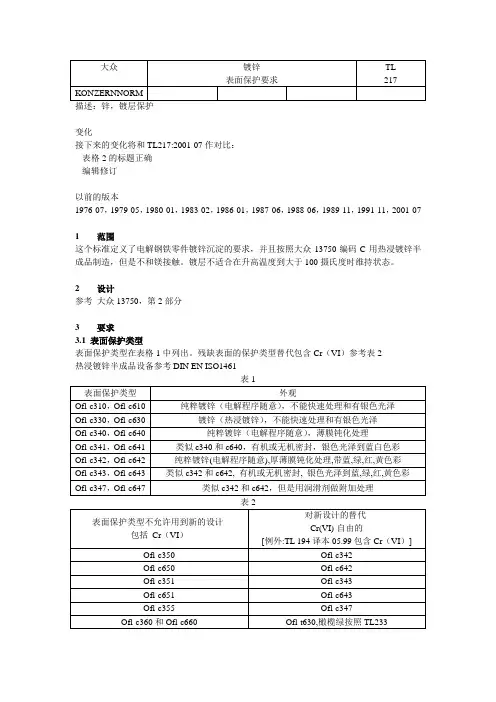
2设计参考大众13750,第2部分3要求3.1表面保护类型表面保护类型在表格1中列出。
残缺表面的保护类型替代包含Cr(VI)参考表2热浸镀锌半成品设备参考DIN EN ISO1461表1表面保护类型外观Ofl-c310,Ofl-c610纯粹镀锌(电解程序随意),不能快速处理和有银色光泽Ofl-c330,Ofl-c630镀锌(热浸镀锌),不能快速处理和有银色光泽Ofl-c340,Ofl-c640纯粹镀锌(电解程序随意),薄膜钝化处理Ofl-c341,Ofl-c641类似c340和c640,有机或无机密封,银色光泽到蓝白色彩Ofl-c342,Ofl-c642纯粹镀锌(电解程序随意),厚薄膜钝化处理,带蓝,绿,红,黄色彩Ofl-c343,Ofl-c643类似c342和c642,有机或无机密封,银色光泽到蓝,绿,红,黄色彩Ofl-c347,Ofl-c647类似c342和c642,但是用润滑剂做附加处理表2表面保护类型不允许用到新的设计-包括Cr(VI)对新设计的替代-Cr(VI)-自由的[例外:TL194译本05.99包含Cr(VI)]Ofl-c350Ofl-c342Ofl-c650Ofl-c642Ofl-c351Ofl-c343Ofl-c651Ofl-c643Ofl-c355Ofl-c347Ofl-c360和Ofl-c660Ofl-t630,橄榄绿按照TL233Ofl-c683Ofl-c686按照TL 194(成分和镁有关)Ofl-c385Ofl-c687按照TL 194(结合元素和镁有关)Ofl-c685Ofl-c687按照TL 194(结合元素和镁有关)3.2普通要求第一次补给和变化,参考大众01155避免危险的物质,参考大众9110110个成品需要完成测试除非按图纸制作的零件的确定部分把表面镀层排除在外,零件的全部表面必须遵守要求的表面保护类型并且显示描述的性质。
描述:锌,镀层保护变化接下来的变化将和TL217:2001-07作对比:- 表格2的标题正确- 编辑修订以前的版本1976-07,1979-05,1980-01,1983-02,1986-01,1987-06,1988-06,1989-11,1991-11,2001-071 范围这个标准定义了电解钢铁零件镀锌沉淀的要求,并且按照大众13750编码C用热浸镀锌半成品制造,但是不和镁接触。
镀层不适合在升高温度到大于100摄氏度时维持状态。
2 设计参考大众13750,第2部分3 要求3.1 表面保护类型表面保护类型在表格1中列出。
残缺表面的保护类型替代包含Cr(VI)参考表2热浸镀锌半成品设备参考DIN EN ISO14613.2 普通要求第一次补给和变化,参考大众01155 避免危险的物质,参考大众91101 10个成品需要完成测试除非按图纸制作的零件的确定部分把表面镀层排除在外,零件的全部表面必须遵守要求的表面保护类型并且显示描述的性质。
在调节和快速固定元件的情况下,列出的测试规格只能应用到主要的和/或者扳手载荷的表面,在螺钉只应用到面朝表面和/或者扳手载荷的表面情况下。
螺纹部件和类似模型部件,象螺栓,测试要求只应用到表面。
后一保护级的测试要求往下应用到确定的步骤在结合的元件例如胫和螺纹上减弱镀层区域。
此外,在DIN EN ISO 4042中的规格,关系到在螺纹图案轮廓电解镀层的最大可能厚度,应该被考虑到。
热浸镀锌制作的部件和附加涂油的半完成品,测试要求只应用到镀锌厚度和按照DIN 50018-KFW 2.0S 的二氧化硫测试中的抗性。
零件的一部分因为制造方法而损伤,比如说:弯曲半径,下一次保护级的要求应用到。
保护的镀层必须显示没有气孔、裂纹、损伤或者其他削弱侵蚀保护和/或者指定外观的瑕疵。
此外,镀层应该展示坚固支持基本材料而且不能在微小的变形后剥落。
设计和生产过程控制不应该削弱成品的功能特征。
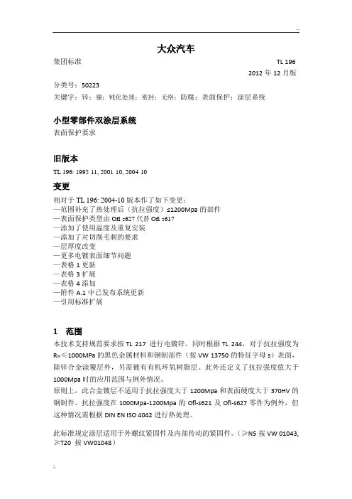
大众汽车集团标准TL 1962012年12月版分类号:50223关键字:锌;镍;钝化处理;密封;无络;防腐;表面保护;涂层系统小型零部件双涂层系统表面保护要求旧版本TL 196: 1995-11, 2001-10, 2004-10变更相对于TL 196: 2004-10版本作了如下变更:—范围补充了热处理后(抗拉强度)≤1200Mpa的部件—表面保护类型由Ofl-s627代替Ofl-s617—添加了使用温度及重复安装—添加了对切削毛刺的要求—层厚度改变—更多电镀表面细节问题—表格1更新—表格3扩展—表格4添加—附件A.1中已发布系统更新—引用标准扩展1 范围本技术支持规范要求按TL 217 进行电镀锌。
同时根据TL 244,对于抗拉强度为R m≤1000MPa的黑色金属材料和钢制部件(按VW 13750的特征字母s)表面,除锌合金涂覆层外,另需镀有有机环氧树脂层。
此外还定义了抗拉强度值大于1000Mpa时的应用范围与例外情况。
原则上,此合金镀层不适用于抗拉强度大于1200Mpa和表面硬度大于370HV的钢制件。
抗拉强度在1000Mpa-1200Mpa的Ofl-s621及Ofl-s627零件为例外,但这种情况需根据DIN EN ISO 4042进行热处理。
此标准规定涂层适用于外螺纹紧固件及内部传动的紧固件。
(≥N5按VW 01043,≥T20 按VW01048)米制螺纹组件适用于环境温度低于90摄氏度的条件下。
米制螺纹紧固件及Ofl-s627适配于一次性螺纹接头。
此涂层系统不为标准的紧固件表面保护方法。
2标记方法见VW 13750 第二章节3技术要求3.1 表面防护类型表面保护类型见表13.2基本技术要求首次供货和变更的批准,按大众标准VW 01155避免有害物质,按 VW 911 01涂层介质及涂层中不能含有络化合物(VI)。
在进行锌涂覆层和锌/镍合金涂覆层时,需以磷化处理作预处理。
薄膜锌磷化适用于紧固件。
Vertragspartner erhalten die Norm nur über die zuständige Beschaffungsabteilung.Confidential. All rights reserved. No part of this document may be transmitted or reproduced without the prior written permission of a Standards Department of the Volkswagen Group.Parties to a contract can only obtain this standard via the responsible procurement department.© VOLKSWAGEN AGN o r m v o r A n w e n d u n g a u f A k t u a l i t ät p r üf e n / C h e c k s t a n d a r d f o r c u r r e n t i s s u e p r i o r t o u s a g e .T h e E n g l i s h t r a n s l a t i o n i s b e l i e v e d t o b e a c c u r a t e . I n c a s e o f d i s c r e p a n c i e s t h e G e r m a n v e r s i o n s h a l l g o v e r n .Q U E L L E : N O L I SDecember 1995Restraint SystemLV 107Seat Belt Vertical AdjustmentRequirements and TestsRestraint system – belt adjustment – requirements and test proceduresPrevious issueAK-LV 13: 1994-12Changes as compared to the 1994:12 issueDocument renumbered and revised without changing the technical contents.Contents1Scope and aim2Normative references3Definitions4General5Requirements and testsA Appendix1 Scope and aimThis specification is meant to ensure that seat belt vertical adjustments installed in standard produc-tion meet the same level of quality as the design tested sample and meet the requirements of the respective national regulations.2 Normative referencesADR 3/02Seat AnchoringADR 4/02Seat BeltsADR 5/03Seat Belt AnchoringASTM B 117 -73 Salt Spray (Fog) TestingECE-R16Seat Belts and Restraint Systems for Motor VehiclesECE-R 21Uniform Conditions for the Approval of Vehicleswith Regard to Their Interior Trim and ComponentsEG 74/60Vehicle Interior Trim and Components, Parts in the Passenger Compartment EG 76/115Seat Belt AnchoringEG 77/541Seat Belts and Restraint Systems for Motor VehiclesFMVSS 571.210 Seat Belt Assembly AnchoragesLV 104Restraint System; Seat Belt Retractor; Requirements and TestsLV 105Restraint System; Belt; Requirements and TestsLV 106Restraint System; Seat-Belt Tensioner; Requirements and TestsLV 108Restraint System; Seat Belt Buckle, Seat Belt Connector; Requirements andTestsLV 109Restraint System; Gas Generator for Seat-Belt Tensioner; Requirements and Tests3 DefinitionsThe seat belt vertical adjustment is a fitting part. All parts of the seat belt system, including locking parts and retractors, which are fastened directly to vehicle parts are considered fitting parts.Continued on pages 2 to 9 LV : Team - Supply SpecificationsTeam of Companies: Audi AG, Bayerische Motoren Werke AG, DaimlerChrysler AG, Porsche AG und Volkswagen AGLV 107 December 1995 Page 24 General4.1 General requirementsThe seat belt vertical adjustment shall have a bottom and a top limit stop. The top and bottom latching position shall also be the final position of the adjusting slide.4.2 DimensionsFor details, see the seat belt vertical adjustment ASSY drawing.4.3 RegistrationThe requirements acc. to EEC 74/60 and ECE-R21 apply in principle.The manufacturer of the seat belt vertical adjustment is responsible for obtaining general type a p-proval and possible cross and mixed registrations at a testing institute authorized for acceptance and for securing the registration in the individual countries.This LV (supply specification) does not relieve the manufacturer from the mandatory documentation of the design test in the specific country acc. to the corresponding specification and the obligation for documentation.5 Requirements and testsThe tests shall be performed in the same sequence as the section numbering. Deviations from this sequence are impermissible.In the unused condition and after the endurance test (section 5.5), the parts shall be rattle-free in driving operation and on the test stand.5.1 ConditioningUnless otherwise indicated, the specimens shall be conditioned for at least 24 h prior to testing at (23 ± 2)° C and (60 +7)% relative humidity.5.2 Corrosion resistance (metal parts in the ASSY)After the corrosion test, the function shall still be fully ensured. Slight corrosion that does not impair the function is permissible with consultation, except in the area adjacent to the body.Testing Salt spray fog test acc. to ASTM B 117-73Number of devices under test (DUT)10 ASSY partsTest setup as-installed position in the vehicleTest duration24 h (for parts not mounted on the floor)LV 107 December 1995 Page 3 5.3 Temperature resistance (non-metal parts in the ASSY)The requirements of this specification shall still be properly fulfilled after testing.In addition, at parts temperatures between -40° C and 85° C, the function and adjustability of the complete lock shall remain intact when the vertical adjustment is operated five times over the entire adjustment range within two minutes of reaching the parts temperature.Requirements similar to ADR 4.02, section 4.7.3.3, with changes.The test shall be performed without interruption acc. to table 1. Temperature gradient to the next aging temperature: 1 K/minTable 1. Temperature, duration and relative humidity in agingAging temperature°C Aging periodhRelative humidity%80–524= 9080–524< 1523–524100+560–5623–56100+560–5623–56100+560–5623–56–40±2245.4 Adjustment force, manual seat belt vertical adjustmentAdditional lubricants may be used to reduce the adjustment force as long as they do not come in contact with the hands or the belt during assembly or operation.Testing in as-received condition and after endurance test (section 5.5) at RT with no vehicle-specific trim panels and without actuating elements:Preload F V = 8NTest regulation see fig. 1Prior to testing, the SBA shall be adjusted 20 times over the entire adjustment range.5.4.1 Basic designUnlocking direction anyUnlocking and/or adjustment force F = 30N5.4.2 Comfort designThe unlocking direction shall be the same as the adjustment direction.The individual latching positions shall be audible or otherwise perceptible.a) Adjustment with force F B from top to bottom only-from any latching position F B = (5 to 13) N-between the latching positions F B = (5 to 10) NLV 107 December 1995 Page 4b) Adjustment with force F T from bottom to top only-from any latching position F T = (2 to 23) N-between the latching positions F T = (2 to 13) Nc) Additional requirementWith a preload of F V = 60 N acc. to fig. 1, unlocking shall be possible with F T = 50 N.Fig. 1. Test regulation for adjustment force5.5 Endurance test and wear characteristicsNo impairment of function after testing.The adjustment forces shall fulfill the requirements in sections 5.4.1 and 5.4.2.Test setup as-installed position in vehicle (or belt 45° in space)without vehicle-specific trim panels andwithout actuating elementsPreload F V = 8NAdjustment speed(5 to 10) adjustment cycles/min1 adjustment cycle consists of: adjustment from the bottom latch to the top and back, locking ineach latching position. A fixed sequence according to the kinematicmechanism of the locking system, which provides maximum loadto the system is also possible.a) Start of endurance testingNumber of adjustment cycles3,000 at room temperatureb) Dust exposureAfter the dust test, the SBA shall lock securely in each latching position.Test stand acc. to ADR 4.02Test setup as-installed position in vehiclewith vehicle-specific trim panel and withactuating elementsDust acc. to EG 77/541Test duration 5 h, dust swirl for 5 s every 20 min. After every dust swirl, runthrough 10 adjustment cycles within (1 to 2) min.c) Continuation of the endurance testNumber of adjustment cycles at room temperature3,000Number of adjustment cycles at -20° C1,000Number of adjustment cycles at 65° C and 95% relative humidity1,000LV 107 December 1995 Page 5d) Vibration loadAfter the vibration load, the SBA shall lock securely in each latching position.Test setup SBA with guide mount (see fig. 2)Preload F V = 8 N, parallel and opposite to direction (1) in fig. 2Vibration form sinusoidalAccelerationand frequency see table 2Frequency change 1 Hz/sDirections of vibration1, 2 and 3 acc. to fig. 2Test duration per direction8hTable 2. Acceleration and frequency of the vibration loadsVibration directions123AccelerationgFrequencyHzAccelerationgFrequencyHzAccelerationgFrequencyHz3.7514 to 25 3.2514 to 23 2.5014 to 252.4025 to 40 2.5023 to 25 2.2525 to 384.2540 to 50 1.7525 to 40 3.7538 to 40–– 2.7540 to 43 4.9040 to 50–– 3.7543 to 48––Fig. 2. Test regulation for vibration load5.6 NoiseIn the unused condition and after the wear test (section 5.5), the parts shall be rattle-free in driving operation and on the test stand.Test duration= 30minTest frequency(0 to 30)HzAmplitude(0 to 2)HzDirections of vibration1, 2 and 3 acc. to fig. 2LV 107 December 1995 Page 65.7 Mounting characteristicsNo impairment of function when the attachment screw or fixing nut of the guide mount is tightened with 60 Nm.5.8 Static strength testThere shall be proof of sufficient strength in all adjustable latching positions and at the bottom stop.5.8.1 Static tensile test on the single partPermissible deformation f = 10 mm in direction of force F.The SBA shall meet the required strength under all angle combinations in table 3. In addition, the requirements for all other angle combinations that are critical for the SBA apply.Test regulation see fig. 3Belt data breaking load= 35 kNElongation at 11 kN8%Test rate75 mm/minMinimum breaking force acc. to F - 3s F =13.0 kN, applies to any latching position and at thebottom stopTable 3. Angle combinationsAngleaß?55°30°13°110°73°13°75°55°13°Measurement F stat./dyn.Dimensions in mmRigid base plate with no permanent deformation under test conditionsFig. 3. Force directions for static and dynamic strength tests5.8.2 Static tensile testTest of the belt anchoring points acc. to EG 76/115, FMVSS 571.210, ADR 3/02 and ADR 5/03No component breakage with a suspension load of 16.4 kN in the shoulder and lap belt parts.LV 107 December 1995 Page 7 5.9 Dynamic testsFor a combination SBA with seat-belt tensioner (automatic tensioner or buckle tensioner), the d y-namic tests shall be performed with tensioners, trim panel parts and actuating elements of the SBA.Tensioner data acc. to LV 106 "Seat-Belt Tensioner".There shall be proof of sufficient strength in all latching positions.For intermediate positions, latching in the next latching position shall be ensured.Intermediate positions are defined as:Locking mechanism 2 mm below the original latching position or the position critical for the locking system.The bottom limit stop shall be able to hold the unlocked slide of the SBA from any possible setting.5.9.1 Tests in intermediate position (tensioner suitability)5.9.1.1 Static testsTensioner with load limit generator (= maximum filling acc. to the manufacturer tolerances).Gas generator temperature directly before detonation set to maximum permissible pressure pulse range.5.9.1.1.1 SBA in connection with automatic tensionerTest setup acc. to fig. 4A SBAS Trim panel with actuating elementsD Automatic tensioner 500+ -50 mm belt on spoolDimensions in mmFig. 4. Test regulation for SBA with automatic tensioner5.9.1.1.2 SBA in connection with buckle tensionerTest setup acc. to fig. 5A SBAS Trim panel with actuating elementD Buckle tensionerDimensions in mmFig. 5. Test regulation for SBA with buckle tensionerLV 107 December 1995 Page 85.9.1.1.3 Slide testThe test shall be performed acc. to ECE-R16 with the following revisions (see fig. 6):-50% TNO dummy, 75 kg-v desired = (56.1 + 1) km/h-36g <= a max < = 40g-G' (a = 40g : t = 18 ms)-H' (a = 40g : t = 55 ms)-Tensioner detonation time t1 electrically detonated seat-belt tensioner: (7 ± 2) ms after t0 (t1 = detonation signal)Fig. 6. Deceleration time curve of the slide5.9.2 Test in latched position5.9.2.1 Slide test acc. to section 5.9.1.1.35.9.3 Test in intermediate latching position5.9.3.1 Slide test acc. to section 5.9.1.1.35.9.4 Additional lock testThe SBA shall be designed so that no destruction or unlocking (except upward) occurs for accel-erations "a" up to 50 g over a time of 10 ms in all directions *) due to the component inertia force. The test shall be performed with guide mounted in as-installed position.*)For acceleration in the y direction (= cross vehicle axis) the part shall unlatch in the next lower position when unlocked.LV 107 December 1995 Page 9A AppendixA.1Appendix 1For information on packaging space and assembly see fig. 7Hole for upper mounting on bodyInternal threads for mounting belt guideM10x1 or M10x1.25 or 7/16"-20 fine-pitch threadBelt guide (not included in SBA)max. 45 mmAdjustment range 92 mm with 5 latching positionsSBA shall be designed so that an adjustmentrange of 69 mm is also possiblewhen omitting or blocking a latchSurface protection cathodic dip paint black3 pairs of hooks for application of force in bodyTrim attachable if needede.g., for versions with guide beneath trim panelmax. 30 mmmax. 20 mmmax. 18 mmDimensions in mmFig. 7.Belt vertical adjustment, dimensioned schematic。
售后服务3售后服务技术信息修理手册Magotan 2008迈腾警车维修手册版本:12.2008汽车技师帮技术资料一汽大众迈腾维修维修手册(2009 一汽大众迈腾警车维修手售后服务3版权所有。
不经法人同意不得使用。
Prin ted in Chi naCopyright (c 2008 Volkswagen AG,Wolfsburg维修手册修理组Magotan 2008工长和机工必需掌握所有技术信息。
因为认真和持久地维护并遵循注意事项是保证车辆行驶和安全的基本条件。
此外在维修时也要遵循维修安全的基本原则。
迈腾警车维修手册版本:12.2008修理组68、91、94、96、97 警车装备汽车技师帮技术资料一汽大众迈腾维修维修手册(2009 一汽大众迈腾警车维修手Magotan 2008迈腾警车维修手册12.2008目录iii3目录68、91、94、96、97-警车装备..........................................................................................................................1中央控制系统.............................................................................................................................................. 1中央控制系统连接示意图........................................................................................................................... 1中控主机-J608-的拆卸和安装.................................................................................................................... 1.3顶部警灯控制器-J326和前后频闪灯控制器-J483-的拆卸和安装............................................ 1.4音频控制器-E507-的拆卸和安装......................................................................................................... 1车载电台-J753-的拆卸和安装.............................................................................................................. 1拆卸和我安装鱼鳍天线............................................................................................................................. 电器............................................................................................................................................................ 2前逆变器-U13-的拆卸和安装 .....................................................................................................................2.2后逆变器-U27-的拆卸和安装............................................................................................................. 车内设备 ................3.1脚铐链的拆卸和安装............................................................................................................................... 3后座椅手铐链的拆卸和安装....................................................................................................................... 拆卸和安装顶部警灯............................................................................................................................ 拆卸和安装电源总开关.............................................................................................................................. 拆卸和安装前/后频闪灯 ......................................................................................................................... 6拆卸和安装前频闪灯 .................................................................................................................................. 6.2拆卸和安装后频闪灯...............................................................................................................................1 1 1 1234 4 4 45 5 56 678 8 8汽车技师帮技术资料一汽大众迈腾维修维修手册(2009 —汽大众迈腾警车维修手Magotan 2008迈腾警车维修手册12.2008目录3iv汽车技师帮技术资料一汽大众迈腾维修维修手册(2009 —汽大众迈腾警车维修手Magotan 2008迈腾警车维修手册12.20081中央控制系统131中央控制系统1.1中央控制系统连接示意图1-车载电台-J753-2-天线3-电源控制器-J644-4扬声器5-后逆变器-U27-6-前逆变器-U13-7-音频控制器-E507-8-中控主机-J608-9-频闪灯控制器-J483-10-前频闪灯11-后频闪灯12-顶部警灯-L5-13-顶部警灯控制器-J326-14-显示器-L145-15-电话话筒1.2中控主机-J608-的拆卸和安装拆卸-关闭点火开关及所有用电器,拔出点火钥匙。
共28页第1页3.3.4 导线压接尺寸3.3.5 导线压接造型3.3.6 绝缘层压接要求3.3.7 单线密封层压接,ELA压接3.4 其他要求3.4.1 分离连接片3.5 特殊的压接形状3.5.1 双止动块3.5.2 封闭式压接套管4 压接连接的制作4.1 模具4.1.1 压接模具试验选用范围4.1.2 认可建议4.2 压接设备4.3 压接力监控4.4 无损检验4.4.1 压接尺寸4.5 有损检验4.5.1 导线拉出力4.5.2 显微图样4.5.3 绝缘层压接检验4.5.4 不合格显微图样样例5 共同适用的资料附录 AA.1 认可建议页面样例A.2 VW 60330 Q对照表:认可试验A.3 VW 60330 Q对照表:生产陪伴试验1 应用范围本标准是对多股软铜细线和细丝制作的绞合导线不采用钎焊而采用压接套管进行电气连接有关鉴定方面的概念、要求和检验标准作了规定。
本标准的规定仅适用于单线固定。
本标准还对压接连接的制作、试验和鉴评方面的要求作了规定。
如遇特殊情况,触片元件和电缆靴标准零件图纸必须给出详细的压接要求。
此外,必须注意触片元件制造商其他有关处理方面的技术规范。
但标准零件各图纸上的规定具有优先地位。
2 概念本标准的概念和定义,以IEV 581标准为准。
各名称参见图1和图2。
图1图例名称说明:1 触片元件范围 4 导体压接7 后部收尾2 连接方式A 5 压接连接8 分离连接片3 前部收尾 6 绝缘压接9 连接方式B图 2图例名称说明:1 触片元件2 导线端部3 导线4 绝缘层2.1 压接连接2.1.1 敞开式压接套管所谓敞开式压接套管,也就是说导线压接、绝缘层压接或者单线密封(ELA)压接具有U 形开口、V形开口或者具有预成形开口的压接方式。
敞开式压接套管通常采用冲裁触片元件。
在压接过程中,在锁紧敞开式压接套管的同时使触片元件与传送条分离。
2.1.2 封闭式压接套管所谓封闭式压接套管,就是导线压接、绝缘层压接或者单线密封(ELA)压接具有封闭式形状。
大众汽车
集团标准TL 217
2009年8月版分类号:50241
关键字:锌;防腐保护;表面涂层
镀锌涂层
表面保护要求
旧版本
TL 217: 1976-07, 1979-05, 1980-01, 1983-02, 1986-01, 1987-06, 1988-06, 1989-11, 1991-11, 2001-07, 2002-07
变更
相对于TL217:2002-07版本作了如下变更:
---第一部分“范围”的扩展
---第3.2部分“一般要求”的修改
---表1中增加对铸铁制动卡钳的要求说明
---原表2中含Cr(VI)表面保护类型删除
---特殊规则的焊接部件介绍(见表3和表5)
---引用的文件更新和补充
---附录“传统表面保护类型”删除
1、范围
本标准规格要求不含Cr(VI),对钢件上的电解离析镀锌层以及按VW13750标识字母“的热镀锌半成品制成的零件要求做出规定,该镀层不适宜长期在大于100℃的高温下使用。
Ofl-c340表面防护类型,必须优先使用于焊接螺栓,焊接螺钉,焊接销和焊接螺母。
注1:此标准已经扩大到包括特殊规则的焊接零件,表面防护Ofl-c340为改善焊接性能(详见表3和表5)
2.标记方法
见VW 13750第二章节
3.技术要求
3.1防护种类
适用于表1中列举的防护种类
对热镀锌半成品的要求见DINENISO1461。
a)用于制动卡钳的铸铁表面防护按Ofl-c343,进一步要求按VDA237-299,05型的涂层厚度,附着力,耐蚀性。
3.2基本技术要求
首次供货和变更的批准,按大众标准VW 01155
避免有害物质按, VW 911 01
进行一次完整的试验要求10个成品件
只要在图纸中未明确标出零件的某些地方不做表面防护,那么此零件整个表面必须遵守指定的表面保护类型及特定属性。
与此相反,连接部分层厚度必须按照DINENISO4042标准,连接部件相关的弱点,如弯曲半径或柄或螺纹区域,防腐要求在这些区域减少到2/3,这一例外不适用于轮毂螺栓。
此外,必须考虑在DINENISO4042中的关于螺纹表面电解涂层的最大厚度的说明。
对于热镀锌且涂油的半成品材料制成的零件,检验要求仅适用于锌层厚度及按DIN50018-KFW2.0S在SO2试验中的耐久性。
防护层不允许有影响防腐性能和/或外观要求的气孔,裂纹,损伤,和其他缺陷。
此外,镀层必须牢牢的附着在基体材料上,在发生较小变形时不允许剥离。
在设计和控制制造工艺时,必须注意不影响成品件的使用性能,尤其是必须保证,通过对预处理和热处理的适当选择和组合,而不会出现氢脆现象。
为避免氢脆,必须在表面处理(离析)后尽快的—但至少在4小时之内且在镀层进行其他处理之前进行所有的热处理(见DINENISO4042)
如果与我们在VW13750第 3.6条第1条中的规定相反,电解离析镀锌层用于Rm>1000N/mm2的高强度钢零件,则这些零件必须在氰化或碱性无氰的镀液中镀锌,此特殊情况必须经测试后才可确定。
3.3用于油漆的镀锌层
对于镀锌后不马上做表面处理的半成品,其电解镀锌层(如从镀锌车间运往油漆车间)为避免上油漆的附着问题,不允许做钝化或磷化处理(Ofl-c310/c610)
对已镀锌件的必要的运输和存储保护如涂油;应与要发往的油漆厂商协商。
如在大众工厂进行油漆,运输或储存保护必须符合质量标准QPA001
此外,即使在镀层厚度较高的边角范围,镀锌层也必须具有完好的附着强度。
3.4 不含Cr(VI)的钝化层
为了改善和提高电解沉积锌镀层抗盐水和冷凝水的能力,通常采用的技术是在钝化液中做再处理。
如使用的钝化液不含Cr(VI)的化合物,由此产生的转换层也将不含Cr(VI)。
镀层厚度约为0.1um的无色和蓝色钝化处理,即薄层钝化,优先适用于车内或行李箱内的区域,在有要求的情况下,也可以附加封闭层。
通过厚层钝化处理(约0.5um)可进一步改善防腐性能。
由于其光学外观(呈彩虹色),这种方法必须密封,确保其适用于乘客可见区域。
钝化处理不应影响零件的使用性能。
当发生不确定情况时,必须咨询相关的工程部(GQL-LM/2,I/GQ-322,N/GQ-551,orI/EG-72)。
3.5密封镀层
在密封过程中,使用有机或无机材料涂覆在事先已形成或局部镀层的转换层上。
附加密封层可使涂层结构的厚度提高0.5-2.0um。
相对于未密封的镀层,密封镀层具有下列优点:
---耐蚀性提高(在不改变锌镀层厚度的条件下,使锌和基体金属出现腐蚀的时间较晚)。
--滑移性能改变(摩擦系数减少,链接元件上离散宽度变小)。
----色彩(厚层钝化的彩虹色明显减少,外观改善)。
3.6结构
3.6.1基本材料
材料按图纸要求
3.6.2 防护类型/外观
见表1
3.7镀层厚度
对于不进行再处理的镀层(如Ofl-c310 and Ofl-c610表面防护类型),可以按照DIN50018用KFW2.0S间接方式来测定镀锌层厚度,确定抗腐蚀强度(见表2)。
或者,按DINENISO1463,DINENISO2177,DINENISO2178,DINENISO2360,和DINENISO3497试验测定涂层厚度。
要求见表3
3.8附着强度
热冲击试验按DINENISO2819
试验件在(220±10)℃,存放30分钟,接着在15-25℃的水中浸泡。
3.9耐腐蚀性
在供货状态以及在120℃进行24小时的热存放后,能确保系统的抗腐蚀性,此为最低要求,任何情况下均应遵守。
3.9.1 钝化和密封
试验方法按DINENISO9227,评估按DIN50961,试验时间和要求见表4。
此测试不包含焊接螺栓,焊接螺钉,焊接销,焊接螺母。
3.9.2 镀层包含钝化和密封
试验方法按DINENISO9227,评估按DIN50961,试验时间和要求见表5.
根据DINENISO13918中表面防护Ofl-c340,为改善焊接螺栓性能可以按TL52132作密封或加润滑剂处理,但不得损害其焊接性。
4.相关参考文献
以下规范为本标准引用,若需要请具体查看。
部分标准由德文标准翻译,译文与德文原文意思可能会因理解不同而有些不同。
部分标题在德文中为专有名词,在其他译本中可能会失真。
QP A001 预润滑,热熔胶,空白洗涤油,油,润滑油(一般),符合质量要求TL 52132 要求,润滑螺纹紧固元件与电解涂层或不锈钢VW 01155 汽车配件供应,首批供货和更改的批准VW 13750 金属表面防护,防护种类,缩写名称,要求VW 91101 汽车环境标准,汽车零件,材料,工业原料;避免有害物质DIN 50018 含二氧化硫环境的冷凝水交变环境试验DIN 50961 电解镀层在铁材上的镀锌层;定义,腐蚀试验和抗腐蚀性DIN EN ISO 13918 焊接螺栓和陶瓷箍电弧焊接螺栓DIN EN ISO 1461 用热镀锌方法在钢铁板上得到的镀锌层(零件镀锌),要求和试验DIN EN ISO 1461 金属涂层和氧化物涂层,涂层厚度测量采用显微法DIN EN ISO 2177 金属涂层,涂层厚度测量;通过阳极氧化溶解的电解式电量计量法DIN EN ISO 2178 在磁性基体金属上的非磁性涂层;涂层厚度测量采用磁化法DIN EN ISO 2360在非磁性基体金属上的非导电涂层,涂层厚度的测量方法采用涡流法DIN EN ISO 2819在金属基体材料上的金属涂层,电解和化学镀层附着强度试验方法概括
DIN EN ISO 3497 在金属基体材料上的金属涂层,涂层厚度的测量采用射线光谱法DIN EN ISO 4042 连接元件,电解镀层DIN EN ISO 9227 人造气体腐蚀实验;盐雾实验
VDA 237-299 Oberflächenschutz für Bremssättel; aus Gusseisen。