比亚迪云服务用户手册
- 格式:pptx
- 大小:18.77 MB
- 文档页数:20
欢迎您选用比亚迪乘用车,为帮助您正确使用和保养车辆,请您务必仔细阅读本手册。
特别说明:比亚迪汽车有限公司建议您选用纯正备件,并按照本手册要求正确使用、维护、修理车辆,使用非纯正备件更换、改装车辆将影响整车的性能,特别是安全性和耐久性,对此产生的车辆损坏及性能问题,均不在保修范围之内。
除此之外对车辆的改装还有可能触犯国家法律法规和当地政府条例。
感谢您选用比亚迪乘用车,欢迎您提出宝贵意见和建议,为了确保更好的为您服务,请务必提供准确的联系方式,如有变更,请及时联系比亚迪汽车授权服务店在系统上更新,同时,请您及时关注国家相关法律和法规及当地政策规定,尽快为车辆上牌,否则可能存在无法上牌风险。
本手册中,注有“温馨提示”、“注意”和“警告”提示的地方,必须小心根据提示的内容来避免受伤或损坏的可能性。
提示类型的表示和使用方法如下所示:本手册中带有“*”标号的描述仅适用于部分车型,使用图片仅采样于其中一个配置,如与您所购车辆有差异,请以实车为准。
2左图所示的安全标记表示“不可以如此做”或“不可以让此发生” 。
本手册的用途在于帮助您正确地使用产品,并不代表对本产品配置及软件版本的任何说明。
有关产品配置和软件版本情况,请查阅与本产品相关合约(若有),或咨询向您出售产品的销售商。
动力电池回收网点查询请登录比亚迪汽车官网:https:///cn/socialresponsibility/batteryrecycle.html详细的产品使用说明请扫描以下小程序二维码查询:202201版比亚迪汽车工业有限公司版权所有未经比亚迪汽车工业有限公司书面许可不得转载或复印本手册的部分或全部内容翻版必究05比亚迪驱逐舰05混动车型搭载了比亚迪最新的双模系统,系统将发动机、 电机、动力电池融合,在兼顾动力性、经济性、NVH 等关键性能,同时让用户可以拥有EV/HEV 驱动模式及ECO/NORMAL/SPORT 等工作模式的体验。
动力电池为电动机驱动车辆提供电能,同时也可以为12V(伏)启动铁电池充电。
比亚迪远程更新使用手册1注意1、本手册是远程更新软件的用户使用手册,主要是为指导用户使用本产品而编写;2、本手册针对远程更新的最终用户,默认用户已具备基本的汽车驾驶技能,熟悉比亚迪多媒体操作系统,掌握比亚迪软件的基本使用方法;3、进行下载更新数据时,请确保3G信号环境良好;4、运行远程更新软件时,请认真阅读操作步骤,并确保将车辆停放在了安全地点;5、进行更新时,车辆会处于停止状态,并且不能启动发动机,请保证在更新过程中不启动车辆;6、操作时请遵守多媒体操作规则和要求,如果出现异常,请关闭多媒体设备,并重新启动系统;7、本用户手册所述内容仅作为介绍功能操作所用,由于软件不断升级变化,实际使用中请以当前版本为准;8、比亚迪将保留对本手册更正或更改其中信息及说明的权利,恕不另行通知且不承担任何责任。
2目录第1章软件使用向导 (4)第一步进入远程更新软件 (4)第二步显示下载模块数据 (5)第三步下载完成 (6)第四步提示更新数据 (7)第五步提示更新所需条件 (8)第六步更新检测界面 (9)第七步显示更新条件满足界面 (10)第八步显示更新模块数据 (11)第九步开始更新 (12)第十步完成更新提示 (13)第2章软件界面详解介绍 (14)2.1软件界面介绍 (14)2.1.1 下载界面详解 (14)2.1.2 更新界面详解 (25)2.2 常用功能图标详细介绍 (46)3第1章软件使用向导第一步进入远程更新软件多媒体启动后,远程更新软件就会自动扫描,如果发现有需要下载的模块,就会提示用户下载4第二步显示下载模块数据显示下载模块基本信息,如模块名称、版本信息(本地版本信息和服务器最新版本信息)、功能5第三步下载完成下载完成后,程序会自动提示用户重启多媒体注:程序会提示用户是否现在进行更新,如果选择确定,多媒体将自动重启;选择取消,程序会返回到多媒体界面6第四步提示更新数据重启多媒体后,远程更新软件发现有更新模块,就会提示用户进行更新7第五步提示更新所需条件更新所需条件:汽车停在了安全地点、车辆发动机不启动、电源档位为ON档、汽车处于空档或P档、并且手刹拉起8第六步更新检测界面如果检测到发动机启动,更新检测界面会提示用户,挂空档/P档,拉起手刹,然后熄火;在不踩离合和刹车时,连续按两次启动按钮,点亮多媒体和仪表的屏幕!9第七步显示更新条件满足界面更新条件满足后,系统会提示用户,并告知用户可进行更新10第八步显示更新模块数据进入更新主界面需要按照更新提示操作:发送机熄火、档位为P档或空档、手刹拉起后注:当进入更新程序界面后,启动按钮和多媒体重启按钮功能会被暂时屏蔽。
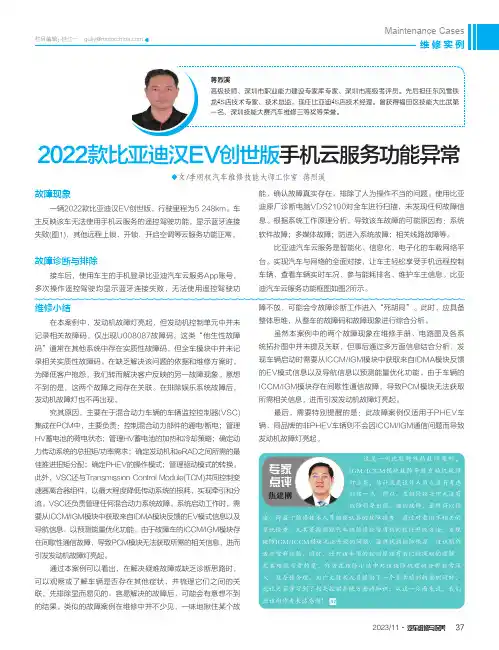
◆文/李明权汽车维修技能大师工作室 蒋烈溪2022款比亚迪汉EV创世版一辆2022款比亚迪汉EV创世版,行驶里程为5 248km。
车主反映该车无法使用手机云服务的遥控驾驶功能,显示蓝牙连接失败(图1),其他远程上锁、开锁、开启空调等云服务功能正常。
故障诊断与排除接车后,使用车主的手机登录比亚迪汽车云服务App账号,多次操作遥控驾驶均显示蓝牙连接失败,无法使用遥控驾驶功迪原厂诊断电脑VDS2100对全车进行扫描,未发现任何故障信息。
根据系统工作原理分析,导致该车故障的可能原因有:系统软件故障;多媒体故障;防进入系统故障;相关线路故障等。
比亚迪汽车云服务是智能化、信息化、电子化的车载网络平台。
实现汽车与网络的全面对接,让车主轻松享受手机远程控制车辆、查看车辆实时车况、参与能耗排名、维护车主信息。
比亚迪汽车云服务功能框图如图2所示。
维修小结在本案例中,发动机故障灯亮起,但发动机控制单元中并未记录相关故障码,仅出现U008087故障码。
这类“他生性故障码”通常在其他系统中存在实质性故障码,但全车模块中并未记录相关实质性故障码。
在缺乏解决该问题的依据和维修方案时,为降低客户抱怨,我们转而解决客户反映的另一故障现象。
意想不到的是,这两个故障之间存在关联。
在排除娱乐系统故障后,发动机故障灯也不再出现。
究其原因,主要在于混合动力车辆的车辆监控控制器(VSC)集成在PCM中,主要负责:控制混合动力部件的通电/断电;管理HV蓄电池的荷电状态;管理HV蓄电池的加热和冷却策略;确定动力传动系统的总扭矩/功率需求;确定发动机和eRAD之间所需的最佳推进扭矩分配;确定PHEV的操作模式;管理驱动模式的转换。
此外,VSC还与Transmission Control Module(TCM)共同控制变速器离合器组件,以最大程度降低传动系统的损耗,实现牵引和分流。
VSC还负责管理任何混合动力系统故障。
系统启动工作时,需要从ICCM/IGM模块中获取来自IDMA模块反馈的EV模式信息以及导航信息,以预测能量优化功能。

比亚迪 L3轿车使用手册比亚迪L3轿车使用手册比亚迪L3轿车使用手册前 言欢迎您选用比亚迪L3轿车。
为帮助您正确使用和保养比亚迪L3轿车,请在使用之前务必仔细阅读本手册所提及的每一个细节。
特别警示:请在公路上行驶,禁止对比亚迪L3轿车最终装配后的车辆进行改装、加装或零部件的变更,包括对车身、底盘或部件的变更。
否则由此引起的车辆损坏或失效以及任何连带损害,将由顾客自行承担。
本手册中,注有“警告”提示的地方,必须小心根据提示的内容来避免受伤或损坏的可能性。
提示类型的表示和使用方法如下所述: 安全标记本手册中所提供的图形为示意图,仅供参考,若图形与实物不符,以实物为准。
感谢您选用比亚迪L3轿车,欢迎您提出宝贵意见和建议。
用车交流请登陆比亚迪汽车俱乐部迪车会论坛:/bbs比亚迪汽车有限公司保留本手册中技术特性和内容的修改权,不受任何约束,也无须事先通知。
警告避免危及车辆或人身安全的事项 为使检修方便等而必须遵守的事项上图所示的安全标记表示“不可以如此做”或“不可以让此发生”。
比亚迪 L3轿车使用手册目录一、起动及驾驶注意事项 (1)发动机的起动方法 (1)开车前的安全检查 (1)各种情况下驾驶的注意事项 (1)燃油 (3)燃油关闭系统 (3)油耗高的因素 (3)机油 (4)三元催化器 (5)发动机排气警告 (5)二、发动机的保养 (6)保养 (6)比亚迪L3轿车保养计划 (6)三、组合仪表 (10)四、组合开关 (14)五、音响系统 (16)六、空调 (21)七、蓄电池 (23)八、安全辅助约束系统(装有时) (24)九、车身、底盘 (30)座椅、安全带、转向盘和后视镜 (30)电动外后视镜 (33)比亚迪L3轿车使用手册车内后视镜 (34)钥匙 (34)智能进入和起动系统 (40)电动门窗 (45)电动天窗(装有时) (46)行李箱盖 (47)发动机罩 (48)燃油箱盖 (48)驻车制动器 (49)悬架和底盘 (49)轮胎与车轮 (49)十一、制动系统 (51)十二、防止轿车腐蚀 (54)十三、防止轿车发生火灾 (56)比亚迪 L3轿车使用手册一、起动及驾驶注意事项发动机的起动方法(a)起动之前1、关闭所有不需要的灯和附属设备。
比亚迪G6使用手册说明书比亚迪G6 乘用车使用手册比亚迪汽车精诚服务承诺亲爱的顾客:您好~因为有了您的关注,我们的部分服务高于行业标准;因为有了您的建议,我们不断追求更优秀的服务。
为了给您提供卓越的服务,我们承诺:一、无论何时,微笑是我的脸庞,热情是我的身躯;二、我会给您一个干净的休憩环境;三、我会在您进店的第一时间接待您;四、我会在维修前对机修项目进行估价;保养项目即刻给出最终价格;新增项目得到您确认后再进行;结算前,我将再次与您逐项进行核对;五、我会对维修保养的时间进行预估并积极跟进,若有延迟,我会第一时间通知您。
若您想了解维修进度,我会在 10 分钟内给您答复;六、在维修过程中,我会为您的爱车使用内饰保护6 件套、外观保护3 件套;七、提供原厂纯正配件,不以假乱真、以旧充新;八、无论您有任何疑问或需求,我都会积极给您回应,一跟到底;九、我会在您离店3 日内进行回访,确保您的爱车正常行驶;十、我会非常感谢您对我的服务质量提出意见,我会记录您的每一条投诉或抱怨,并积极解决。
7>201202 版深圳市比亚迪汽车有限公司版权所有未经深圳市比亚迪汽车有限公司书面许可不得转载或复印手册的部分或全部内容翻版必究比亚迪G6 乘用车使用手册比亚迪G6 乘用车整车参数QCJ7201EQCJ7151ET1 QCJ7151ET2产品型号名称MT MT DCT外形尺寸长×宽×高 mm (毫米) 4860×1825×1463 轴距 mm 毫米) 2745轮距 mm (毫米)1555轮胎规格 205/60R16 215/50R17接近角(满载) ?(度) 14离去角(满载) ?(度) 16前悬/后悬 mm (毫米) 1025/1090乘员数5最大爬坡度 % 35最大车速 km/h (公里/小时) 180 180发动机型号 BYD483QB BYD476ZQA型式直列四缸,水冷,双顶置凸轮轴直列四缸、涡轮增压、燃油直喷、双顶置凸轮轴DOHC排量 ml (毫升) 1991 1497发动机最大净功率 kW 100 103最低经济油耗* L/100km 8.3 7.0额定功率 (kW/rpm) 103/6000 113/5200额定扭矩 (kW/rpm) 186/ (4000-4500)240/ (1750-3500)排放水平国四国四整备质量 1440 1450最大允许总质量 1815 1825质量参数(kg) 轴空载前轴 860 875荷后轴 580 575分前轴 990 1000配满载后轴 825 825轮胎的动平衡要求车轮总成每个边打完平衡块后再测量的不平衡量应小于5g(* 实际油耗与车况、道路条件、驾驶习惯等因素有关)比亚迪G6 乘用车使用手册前言欢迎您选用比亚迪 G6 乘用车。
比亚迪远程启动操作方法
比亚迪远程启动操作方法主要有以下几种:
1. 使用比亚迪的远程控制器:根据车辆的型号和配备的设备,比亚迪提供不同类型的远程控制器。
通过按下相应的按钮,可以启动或停止车辆。
2. 使用比亚迪官方手机APP:比亚迪提供了专门的手机APP,通过该APP登录并绑定车辆后,可以通过手机远程启动车辆。
操作方法包括选择车辆并点击启动按钮。
3. 使用车钥匙上的远程启动按钮:一些比亚迪车型的钥匙上配备了远程启动按钮。
按下该按钮一定时间后,车辆即可启动。
该方法一般适用于较新的比亚迪车型。
需要注意的是,在进行远程启动操作前,需要确保车辆处于停止状态,并且在没有人员靠近的情况下实施操作,以确保安全。
同时,在某些地区和法律规定下,可能要求取得相应的许可或遵守特定的规定才能进行远程启动操作。

前言比亚迪汽车销售服务店应遵循比亚迪汽车公司采用的售后服务流程, 达到并超越顾客的期望,确保在比亚迪汽车销售服务店与顾客之间建立互相信任的,长期的关系基础。
比亚迪汽车公司根据售后服务的工作内容,将售后服务过程的核心内容经过组织编排,形成本售后服务流程。
该流程的内容将服务过程分为:预约、接待、车间生产、跟踪服务四大部分。
其中接待部分是本流程中的核心部分,是与顾客直接接触的过程。
车间生产是整个服务店内部工作。
制定此流程的目的是规范和加强比亚迪汽车销售服务店的管理工作,以提高客户满意度,确保比亚迪汽车销售服务店在管理水平上整体提升。
比亚迪汽车销售有限公司2006年10月20日目录第一章预约 (1)第一节 预约的要点 (1)第二节 顾客来电预约工作项目 (3)第三节 预约服务管理工具 (7)第二章接待 (11)第一节 准备 (12)第二节 接车 (14)第三节 环车检查 (15)第四节 问诊 (16)第五节 确认维修项目与价格 (18)第六节 安排顾客休息或送走 (20)第七节 信息反馈项目追加 (21)第八节 交车前准备 (23)第九节 交车确认 (25)第十节 结帐送行 (26)第十一节 电话接待工作 (28)第十二节 接待工作管理工具及使用介绍 (31)第三章车间生产 (39)第一节 调度生产 (40)第二节 质量控制 (45)第三节 车间生产管理工具及使用介绍 (47)第四章跟踪服务 (48)第一节 定期提醒服务 (48)第二节 修后跟踪服务 (51)第三节 修后跟踪和提醒服务管理工具和使用方法 (54)第一章预约第一节 预约的要点1预约的要点明快的声音,使用明快“亲切的语调与顾客交谈”。
总是面带微笑,不要因为是电话交谈态度就很随便,态度要认真,好像对方能看到自己一样。
端正的姿势。
虽然对方看不到自己的姿势,但自己的态度会不自觉地表现在声音上。
所以坐姿要端正,收和脚不要有过多的小动作,身体略微前倾来接听电话。
比亚迪 L3轿车使用手册 比亚迪L3轿车使用手册比亚迪L3轿车使用手册前 言尊敬的用户:恭喜您选用比亚迪L3轿车。
为帮助您正确使用和保养比亚迪L3轿车,请在使用之前务必仔细阅读本手册所提及的每一个细节并遵守相关规定。
特别警示:请在公路上行驶;禁止对比亚迪L3轿车最终装配后的车辆进行改装、加装或零部件的变更,否则由此引起的车辆损坏或失效以及任何连带损害,将由顾客自行承担。
本手册中,注有“警告”和“安全标记”提示的地方,请务必仔细阅读。
如果不按照警告中的提示及操作方法使用车辆,将会危及车辆及人身安全或使检修 复杂而造成时间浪费和经济损失。
本手册中所提供的图形为示意图,仅供参考,若图形与实物不符,以实物为准。
本手册包括截止至该手册印刷时的最新信息。
比亚迪汽车有限公司全权负责 该手册的修订和说明,并保留该手册印刷后更改产品而不另行通知的权利。
本手册最终解释权归比亚迪汽车有限公司所有。
用车交流请登陆比亚迪汽车俱乐部迪车会论坛:/bbs上图所示的安全标记表示“禁止如此操作”或“禁止让此发生”。
安全标记比亚迪 L3轿车使用手册目 录发动机的起动方法 (2)开车前的安全检查 (2)各种情况下驾驶的注意事项 (3)燃油 (4)燃油关闭系统 (4)油耗高的因素 (5)机油 (5)三元催化器 (5)发动机排气警告 (6)二、发动机的保养 (7)保养 (7)保养计划 (7)三、组合仪表 (11)四、组合开关 (15)五、音响系统(装有时) (17)车载CD面板使用说明 (17)“电源开关/音量”旋钮:通过旋转旋钮,可调 (17)节音量高低;按动旋钮,开启/关机。
音量调 (17)节时,显示屏显示对应音量; (17)“1-6”数字键:RADIO模式:短按,可选择预存到此频道号的电台;长按,将当前频道存储在对应数字键。
(18)比亚迪L3轿车使用手册“FM1”、“FM2”、“AM”键:按下按键,所有模式下切分别切换到调频“FM1”、调频“FM2”、调幅“AM”收音功能。
BYD Battery-Box Premium LVSService Guideline and ChecklistVersion 1.0Valid for Premium LVS 4.0 / 8.0 / 12.0 / 16.0 / 20.0 / 24.0LVS 16.0 (4 Modules + PDU - max. 64 Modules in 16 Towers per System)BMU (1 x per System)Make sure to always use the latest version of this service document,available at: Important: The installation and all other kinds of works or measurements in combination with the Battery-Box Premium are only allowed by professional and qualified electricians.This checklist is a shortened assistance for the Battery-Box and does not replace the original manual,which can be found on w /w ww.eft-systems.de/w .au.Subject to technical modifications;no responsibility is accepted for the accuracy of this information.Attention:Improper handlingCONTENTCONTENT 21. GENERAL STEPS32. ERROR ANALYSIS 42.1 BMU shows no reaction / No LED 42.2 Communication problem with Inverter 52.3 Problem with the Firmware Update / App Configuration 62.4 BMU/BMS LED Event Code (EC)72.5 Be Connect Plus (BCP)82.6 Voltage measurement and undervoltage92.7 Visual Check112.8 Identifying a faulty module113. SERVICE TASKS123.1 BMU Replacement123.2 PDU Replacement123.3 LVS Module Replacement12 SERVICE CHECKLIST AND CONTACT INFORMATION13Make sure to always use the latest version of this service document, available at: w Please proceed first with the installation steps by:1. GENERAL STEPSNo. Name Description1 Configuration Check if the configuration is correct. Refer to latest “BYD Battery-Box Premium LVSMinimum Configuration List” (V1.1 or above) available at: w Make sure the inverter is configured correctly.2 Correct externalcabling munication to invertera.Depending on the choice of inverter the cable between the BMU portand the inverter must be specially made. Please check thespecifications in the installation manual.b.Recommended CAT5 or higher;c.Check the cables and replace them if necessary2.Groundinga.Battery-Box connected directly to the ground-bus of the house.b.The battery must not be earthed via the inverter! Otherwise,communication problems are possible.3.Ethernet-Cable for Internet (s trongly recommended!)4.DC-Ports - Make sure that +and - a re properly connected. (Male DC Connectorpiece required)5.Correct parallel connection cabling if applicable3 Latest FirmwareAlways install / update the n ewest Firmware!Note: If not stated otherwise, wifi password is BYDB-Box4 App Configuration To complete the commissioning, the configuration of the battery via “Be Connect” Appis m andatory!5 Restart After app configuration, please perform a proper restart of the system by switching offthe battery correctly (press LED Button on B MUfor 5 sec). Make sure all LEDs of thebattery are completely off. Then follow the correct switch on procedure (see step 6)6 Switch on procedure Correct switch on procedure is important for a correct operation!1.Switch on the fuse between Inverter and Battery (if there is any)2.Switch on the Battery-Box (LED Button on the top L VS module)3.Activate the inverter7 Checking the correctoperation The system runs properly if:- Inverter displays battery SOC correctly- System charges / dischargesNote: If you can not complete the commissioning, then turn off the battery before you leave the site and make sure all LEDs are off to avoid a discharge of the battery.2.1 BMU shows no reaction / No LEDLEDs of BMU do not light up, although the battery is ON.2. ERROR ANALYSISPlease refer to the general steps before proceeding, see chapter 1.No. NameDescription8Check correct cable portMake sure that the correct data cable port has been used at the BMU (“BMS” port. Do not mix with “inverter” or “Ethernet” port).9 Unplug Comm CableSometimes might be necessary to unplug the communication cable and plug it back again when the batteries are switched on.10 Replace Comm Cable Try a completely new communication cable between battery and BMU.11Voltage measurement on pin 7&8Measure the voltage of PIN 7 & 8 while the other side of the cable is connected to the IN port of the Battery-Box and while the Battery-Box is powered on. Voltage should be around 50V. If yes: try another BMU (if available). If no: check another cable or try another LVS if multiple batteries are installed in the system..12Only LED faulty?In some rare cases, the LED of the BMU is faulty. To check that: check if there is a WIFI access point of the Battery-Box and check if there are internal LEDs inside the BMU. If so, only the external LED is inactive and a commissioning could still work. 13 Voltage measurement Check voltage of battery. See S ection 2.614BMU exchangeOnly if voltage between pin 7&8 are okay, correct comm port is used, voltage seems correct and the cable between the Battery and the BMU was exchanged: Test another BMU, if available.2.2 Communication problem with InverterNo. Name Description15ConfigurationCheck if the configuration is correct. Refer to latest “BYD Battery-Box Premium LVS Minimum Configuration List” (V1.1 or above) available at: Make sure the inverter is configured and working correctly.16 Communication cable- Confirm PIN / Cable Configuration for the specific inverter model (see manual) - Replace the communication cable (min. CAT5!)17 Check terminal resistorMake sure that the terminal resistor is connected to the OUT port of the last battery (the battery with the highest address).Terminal resistor properties: 120 Ω resistor between pin 5 and 618App Configuration and FirmwarePlease check if the App configuration was successful and the Firmware is the most recent one. If there are problems, please refer to S ection 2.319Restart the entire system1. Switch off the Inverter2. Switch off the battery (Press button on BMU for 5 seconds until all batteries switch off)3. Wait for 2 Minutes4. Turn on the Battery (button on any battery) and then5. Turn on inverter second20 Further checkingIf problem remains:- Download all data with BCP (section 2.5) - Check the inverter- Try by replacing the BMU, if available2.3 Problem with the Firmware Update / App ConfigurationThe Battery Management consists of two components: the BMU and the BMS. The Firmware Update from the App will update the BMU, which will then update the BMS. T he BMS update can take up to 30 Minutes until the firmware is updated on the BMS.No. NameDescription21Correct App and FirmwareMake sure to have the latest App Version (>1.5.1) and Battery Firmware (download inside the App) on your mobile device before connecting the app with the battery WiFi.If the App cannot be installed, or other general Problems occur with the App:-Try with a different mobile device (For Android: min Android version requirement is 4.4. ) -Try with PC Tool BCP (s ection 2.5) 22App reports: “Dataconnection busy” / “Data connection failure.” Battery-Box is busy (e.g the battery could be updating the firmware). Please wait 10 minutes and try again.23Close and restart the AppIf the App does not react anymore after some minutes loading during the update process, close (close the program completely) and restart the App. Or try with P C Tool BCP (s ection 2.5)24BMS Version not updatedThe App will only update the BMU. The BMU will update the BMS, which c an take up to 30 minutes.If the BMS Version is not updated after 30min with stable inverter communication, follow the below Process:1.Update Firmware through the App again2.Restart the systema.Switch off the Inverter first, then switch off the battery second(Press LED for 5 seconds) b.Wait for 2 Minutesc.Turn on the Battery first, then turn on the inverter second3.Wait for 30 Minutes4.Check BMS Firmware Version again with App. If Version is still wrong, dothe update process again (if possible with another mobile device).2.4 BMU/BMS LED Event Code (EC)A constant white LED refers to standby mode. White blinking means charge or discharge.When the battery is initiating, the LED will flash white and blue with an interval time of 0.5 seconds (normal during startup). When the LED flashes blue with an interval time of 1 second it indicates an event code. We start to count when the white LED begins to flash, then we count how many times white and blue LED flashes. (also refer to the manual!)Example: 1xwhite, 6xblue → EC 106 / 1xwhite, 11xblue → EC 111 / 3xwhite, 3xblue → EC 303Most Errors come from a faulty communication line, incorrect app configuration or missing restart after app-configuration. Please go in detail through: S ection 2.2 & 2.3Note: if the system is not correctly configured with the app, the event code (EC) might be misleading.EC BMU ECBMSMeasureEC 101 all - Download all data with BCP (especially the historical data)(section 2.5)If problem remains: replace BMU, if availableEC 102EC 105all- Make sure app-configuration has been completed correctly (especially module quantity!).- Check terminal resistor- replace communication cable b etween Battery and BMU- Restart system according to manual. (note: to properly shut down you need to press the buttonon BMU for 5 seconds. Make sure to start the battery before starting the inverter!)- If the problem rema ins, check the connection ports of the LVS Modulewith the LED white andblue blinking and the module above this one. If all modules show this blinking, check the topmodule first (see section 2.7)- Download all data with BCP (especially the historical data)(section 2.5)- Check if the system works when removing t he suspected module(see section 2.8)If problem remains: replace BMU, if availableEC 103EC 108- Check DC cabling and make sure that the Minimum Configuration is met.- Check the voltage of the batteries with BCP according to s ection 2.5 / 2.6- Restart system properly (see S tep 19,section 2.2; especially make sure that fuse betweenbattery and inverter is closed, if there is a fuse)- Download all data with BCP (especially the historical and cell data)(section 2.5)- Check if the system works when removing t he module with the EC(see section 2.8)- provide the SN and voltage of the faulty module (see checklist on last page)EC 104 EC 101 - Check DC cabling (is there any short circuit? Fuse between battery and inverter closed?)- Disconnect the battery system from the inverter and restart the battery system alone (batteryisolated), to evaluate if the error is being caused externally (i.e. short circuit in inverter or mppt). Ifthe Event Code remains, the error might be in the battery. If the Event Code has changed, theremight be an error in the inverter side.- Download all data with BCP (especially the historical and cell data)(section 2.5)- Check if the system works when removing t he module with the EC(see section 2.8)- provide the SN and voltage of all modules with the EC (see checklist on last page)2.5 Be Connect Plus (BCP)Be Connect Plus is a Windows-PC tool. With Be Connect Plus (BCP) you can:-read the battery information, -configure the battery system -update BMU & BMS firmware -Export / download battery logs (From BMU and all BMS)BCP is constantly being improved and updated. Make sure to use the latest program version. You can download the latest version of the Tool on / www.eft-systems.de / .au.For the service analysis, please download and provide the data / logs as described in the program instructions (see PDF manual inside of program ZIP archive).Note: You need a windows computer that will be connected to the battery Wifi.EC 104EC 102 up to EC113(All other than 101)- Download all data with BCP (especially the historical and cell data) (section 2.5) - Check the voltage of the batteries according to s ection 2.6- Check if the system works when removing t he module with the EC (see section 2.8)- provide the SN and voltage of the module with the EC (see checklist on last page) EC 106 all- Make sure the inverter is on, configured and working correctly. - Check according to section 2.22.6 Voltage measurement and undervoltageAttention: Make sure not to create a short circuit!-You can see the max. and min. cell voltage in the BeConnect App.-You can also get the detailed module and cell voltage in the BCP Program (section 2.5)-or measure it manually according to the below description:To check the voltage on the PDU, the Modules have to be ON and the BMU has to be connected with the PDU! (LEDs on Modules and BMU have to be ON)Please measure at P+and P-according to the below picture:The voltage measured on the PDU is the combination / average voltage of all modules in the tower. This should be around 50 V. If it is not around this value, please measure the voltage of each individual LVS Module by one of the following two possibilities (please note, that you cannot measure the correct voltage in any other way).1.Only put one Module in the tower and measure the voltage according to the above process on the PDU.(Make sure the LVS Module is ON and BMU connected when you measure the voltage on the PDU).2.If the modules cannot be activated, or you cannot get a correct voltage value, the other option tomeasure the voltage in one LVS module is by opening the module according to the below process:To check the voltage, you need to disassemblethe right side of the battery module (the side withthe LED). Then follow the procedure described onthe next page.Attention: Make sure not to create a short circuit!The voltage should be about 50 V.Measure the voltage at the below marked “BAT+” and “BAT-”.Measurement shown here:UndervoltageA Module in which one of the 16 cells has a voltage of <1.5 V is in undervoltage (check with BCP (section 2.5) / BC if possible).- LVS Modules with >45 V should be fine and you can continue to check other points according to this service guideline.- If the module voltage is <40V but the single cell voltage is >1.5V, the battery needs to be charged quickly while avoiding any further discharge. Therefore shutdown the system and search the problem according to the guideline, while the battery is completely off. Also check on the inverter side why the force charge doesn’t work. Do not turn on the battery before making sure the inverter should be able to charge the battery.- If only one module is in undervoltage: remove that one and try commissioning without it (if the remaining modules still comply with the Compatible Inverter List). Otherwise, make sure to avoid further overdischarge. (Turn off the system completely)- If one, or all modules are in undervoltage: Contact the service as stated below and make sure to avoid any further discharge of the battery (Turn off the system completely)When contacting the service, make sure to fill the service checklist completely and add the following information: -Serial Numbers (of the BMU and all (affected) modules)-Individual module voltages of all modules (related to Serialnumber)-If possible: Logs from the battery using BCP (section 2.5) and Screenshots showing the cell voltages-Initial Firmware (FW) Version of the Battery when the UV happened (BMU and BMS)-Detailed description how and why the system reached Undervoltage if known. Information when the system was installed and commissioned and in which circumstance and when the undervoltage happened. If the battery wasnever running before: Why did it never work before, and what was the Batteries status when the battery was left (on / off / LED).-Inverter Model, Serial Number and Inverter Logs-Access to Inverter portal (add i******************and tell us the name of the system in the portal)2.7 Visual CheckThe PINs should not be bent. A module with twisted pins will still work as long as it is the bottom module in the tower. So if you find twisted pins in a module, make sure to position that module in the bottom of the tower.2.8 Identifying a faulty module-The module quantity must be adjusted in the app whenever the number of modules is changed!-Please perform a visual check of the communication pins according to step 2.7 for each module.-Normally a faulty module can be identified with the Be Connect Plus Program or by the LED Code in the Battery Module. In this case, remove the Module with the Event Code from the system, and commission the remaining system (if it still complies with the minimum configuration list) and check if it runsproperly. If the problem remains, please also check the module above the one with the Event Code.-Otherwise, try the LVS Modules one by one, or by adding Modules one by one into the tower and always check if the system can work properly to identify a possibly faulty module.3.1 BMU ReplacementHave you detected a faulty BMU?:After replacing the BMU, please do not forget to re-do the configuration and firmware-update in the app.3.2 PDU Replacement3.3 LVS Module ReplacementAfter replacing a Module, please do not forget to re-do the configuration and firmware-update in the app. (Every module has its own BMS)3. SERVICE TASKSPlease go through the general steps beforehand, see chapter 1.Important: The installation and all other kinds of works or measurements in combination with the BYD Battery-Box are only allowed by professional and qualified electricians. Improper handling can cause danger and damage. This document does not replace the official BYD manuals and documents. No responsibility is accepted for the accuracy of the information..BYD Battery-Box Premium LVS Service Checklist - V1.0 ENService Contact: Europe: EFT-Systems GmbH Australia: Alps Power Pty Ltd。
比亚迪 L3轿车使用手册比亚迪L3轿车使用手册比亚迪L3轿车使用手册前 言欢迎您选用比亚迪L3轿车。
为帮助您正确使用和保养比亚迪L3轿车,请在使用之前务必仔细阅读本手册所提及的每一个细节。
特别警示:请在公路上行驶,禁止对比亚迪L3轿车最终装配后的车辆进行改装、加装或零部件的变更,包括对车身、底盘或部件的变更。
否则由此引起的车辆损坏或失效以及任何连带损害,将由顾客自行承担。
本手册中,注有“警告”提示的地方,必须小心根据提示的内容来避免受伤或损坏的可能性。
提示类型的表示和使用方法如下所述: 安全标记本手册中所提供的图形为示意图,仅供参考,若图形与实物不符,以实物为准。
感谢您选用比亚迪L3轿车,欢迎您提出宝贵意见和建议。
用车交流请登陆比亚迪汽车俱乐部迪车会论坛:/bbs比亚迪汽车有限公司保留本手册中技术特性和内容的修改权,不受任何约束,也无须事先通知。
警告避免危及车辆或人身安全的事项 为使检修方便等而必须遵守的事项上图所示的安全标记表示“不可以如此做”或“不可以让此发生”。
比亚迪 L3轿车使用手册目录一、起动及驾驶注意事项 (1)发动机的起动方法 (1)开车前的安全检查 (1)各种情况下驾驶的注意事项 (1)燃油 (3)燃油关闭系统 (3)油耗高的因素 (3)机油 (4)三元催化器 (5)发动机排气警告 (5)二、发动机的保养 (6)保养 (6)比亚迪L3轿车保养计划 (6)三、组合仪表 (10)四、组合开关 (14)五、音响系统 (16)六、空调 (21)七、蓄电池 (23)八、安全辅助约束系统(装有时) (24)九、车身、底盘 (30)座椅、安全带、转向盘和后视镜 (30)电动外后视镜 (33)比亚迪L3轿车使用手册车内后视镜 (34)钥匙 (34)智能进入和起动系统 (40)电动门窗 (45)电动天窗(装有时) (46)行李箱盖 (47)发动机罩 (48)燃油箱盖 (48)驻车制动器 (49)悬架和底盘 (49)轮胎与车轮 (49)十一、制动系统 (51)十二、防止轿车腐蚀 (54)十三、防止轿车发生火灾 (56)比亚迪 L3轿车使用手册一、起动及驾驶注意事项发动机的起动方法(a)起动之前1、关闭所有不需要的灯和附属设备。
比亚迪的新能源汽车让车主有了全新的用车体验,带来的革新不亚于智能机替代传统手机,当然没驾乘过的自然不会体验到,就像8年前,用传统手机的确不理解用智能机的一样,不接触自然不会带来震撼,包括我身边的朋友,仍然有一些没坐过我车的会说,"加速那么快有什么用,四驱对于我上下班没什么,一年我的油钱也花不了多少等等"(542—百公里加速5秒内、全时四驱、油耗2个),对于此不想再说什么,相信未来会有更多的朋友投入新能源车的阵营!说起我的比亚迪(唐),就不能不说说它的云服务,对于老车主有可能比较熟悉了,但是新进的车主会对云服务的的功能比较陌生,下面我介绍一下比亚迪云服务及故障排除。
一、什么是云服务,都能干什么?是比亚迪自主研发的汽车智能服务手机端,可以轻松实现远程控制,查看实时车况,带您进入车联网的云时代。
简单的说就是将你的汽车联网,可以通过手机、等终端和汽车互联互动,实现远程汽车控制(开空调、解锁、上锁)、定位(GPS定位)、整车检测等功能。
当然在秦和后续的宋、元等车型上实现的功能更多一些。
具体是通过在汽车内部内置了一张上网卡,因此可以和其他任何上网的设备之间进行无线通信。
所以发指令到上网卡就能发到你的车上,同样你的车况信息会反馈到你的手机或其他终端上,便于车主随时了解汽车实时信息!这里说的远程是只要有网络的任意角落,(国外也一样),都可以使用云服务,但是前提条件一定是你和车所处的地方有信号,尤其要提醒的是车不要在高压线和变电站附近,可能会会因为信号干扰让你的指令无法传递。
二、如何下载注册、收费?新车友购车后可以让4S店销售顾问,帮着下载开通,也可以通过迪粉汇应用推荐下载(毕竟官方的让人放心)。
官方下载二维码购买搭载云服务的车辆时,需要在购车4S店登记个人信息和车辆信息,注册云服务;用户首次使用云服务时,需要对云服务进行激活,可通过比亚迪云服务手机应用和云服务用户网两种方式激活。
具体来说您需要①下载安装比亚迪云服务手机应用;②输入在4S店注册云服务帐号时登记的邮箱、手机或者身份证号,点击登陆;③首次登录需要同意比亚迪云服务用户协议,输入密码函中的密码,点击“同意”。