珈玛变频器8000系列说明书
- 格式:docx
- 大小:4.25 KB
- 文档页数:4
VC8000系列高性能矢量变频器综合手册上海格立特电力电子有限公司SHANGHAI GRERT POWER ELECTRONICS CO.,LTD综合手册VC8000 系列通用变频器使用手册前言首先感谢您购买格立特公司开发生产的VC8000系列变频器!VC8000系列变频器是一款通用高性能电流矢量变频器,主要用于控制和调节三相交流异步电机的速度和转矩。
VC8000系列采用高性能的矢量控制技术,低速高转矩输出,具有良好的动态特性、超强的过载能力、功能丰富强大,性能稳定。
可用于纺织、造纸、拉丝、机床、包装、食品、风机、水泵及各种自动化生产设备的驱动。
本说明书介绍了VC8000系列变频器的功能特性及使用方法,包括产品选型、参数设置、运行调试、维护检查等,使用前请务必认真阅读本说明书,设备配套厂家请将此说明书随设备发送给终端用户,方便后续的使用参考。
注意事项为说明产品的细节部分,本手册中的图例有时为卸下外罩或安全遮盖物的状态。
使用本产品时,请务必按规定装好外壳或遮盖物,并按照手册的内容进行操作。
本手册中的图例仅为了说明,可能会与您订购的产品有所不同。
本公司致力于产品的不断改善,产品功能会不断升级,所提供的资料如有变更,恕不另行通知。
如果您使用过程中有问题,请与本公司各区域代理商联系或直接与本公司客户服务中心联系。
在开箱时,请认真确认:本机铭牌的型号及变频器额定值是否与您的订货一致。
箱内含您订购的机器(附产品合格证)、用户操作手册(附产品保修卡)。
产品在运输过程中是否有破损现象;若发现有某种遗漏或损坏,请速与本公司或您的供货商联系解决。
VC8000 系列通用变频器使用手册目录前言...................................................................................................................................................... 1 1 第一章安全信息及注意事项 (6)1.1 安全事项 (6)1.2 注意事项 (8)第二章产品信息 (11)2.1 铭牌说明 (11)2.2 产品系列 (12)2.3 产品外形 (13)2.3.1 变频器产品外形尺寸 (15)2.4 基本技术规格 (18)2.5 制动单元与制动电阻选型表 (20)2.6 EMC(电磁兼容性) (21)2.6.1 相关术语定义 (21)2.6.2 电源输入端加装 EMC 输入滤波器 (21)2.6.3 电源输入端加装交流输入电抗器 (21)2.6.4 变频器输出侧加装交流输出电抗器 (21)第三章安装与接线 (22)3.1 机械安装 (22)VC8000 系列通用变频器使用手册3.1.1 安装环境 (22)3.1.2 安装空间要求 (22)3.1.3 机械安装注意事项 (23)3.2 电气安装 (23)3.2.1 主回路端子说明 (23)3.2.2 变频器主回路接线方式 (24)3.2.3 主回路配线注意事项 (24)3.2.4 控制回路端子说明 (26)3.2.5 端子接线图 (28)3.2.6 主控板跳线设置 (30)第四章键盘操作说明 (31)4.1 操作与显示界面介绍 (31)4.1.1 功能指示灯说明 (31)4.2 键盘按键说明 (32)4.2.1 参数设置 (32)4.2.2 电机参数自学习 (33)4.2.3 密码设置 (35)第五章功能参数表 (35)5.1 基本功能参数简表 (35)5.2 监视参数简表 (68)第六章参数说明 (71)P0 组基本功能组 (71)VC8000 系列通用变频器使用手册P1 组电机参数 (79)P2 组矢量控制参数 (81)P3 组 V/F 控制参数 (84)P4 组输入端子 (92)P5 组输出端子 (102)P6 组启停控制 (107)P7 组键盘与显示 (111)P8 组辅助功能 (116)P9 组故障与保护 (128)PA 组过程控制 PID 功能 (135)PB 组摆频、计数功能 (142)PC 组多段速指令及简易 PLC 功能 (144)Pd 组通讯参数说明 (150)PE 组保留 (152)PF 组功能码管理 (152)A0 组转矩控制和限定参数 (154)A1–A4 组参数保留 (156)A5 组控制优化参数 (156)VC8000通讯数据地址定义 (159)1.1 VC8000 功能码数据 (159)1.2 非功能码数据 (160)Modbus 通讯协议 (163)VC8000 系列通用变频器使用手册1.1 应用方式 (163)1.2 总线结构 (163)1.3 通讯资料结构 (164)1.3.1 数据帧字段说明: (165)1.4 功能码参数地址标示规则 (166)第七章维护保养与故障诊断 (171)7.1 变频器的日常保养与维护 (171)7.1.1 日常保养 (171)7.1.2 定期检查 (171)7.1.3 变频器易损件更换 (172)7.1.4 变频器的存贮 (172)7.2 故障报警及对策 (173)7.3 常见故障及其处理方法 (175)第一章 安全信息及注意事项安全定义:在本手册中,安全注意事项分以下两类危险:由于没有按要求操作造成的危险,可能导致重伤,甚至死亡的情况注意:由于没有按要求操作造成的危险,可能导致中度伤害或轻伤,及设备损坏的情况;请用户在安装、调试和维修本系统时,仔细阅读本章,务必按照本章内容所要求的安全注意 事项进行操作。
目录第1章序言 (1)第2章概述 (2)2.1开箱检查 (2)2.2产品搬运 (2)2.3产品保存 (2)2.4产品保修 (2)2.5铭牌说明 (3)第3章安全注意事项 (4)3.1安装 (4)3.2配线 (5)3.3送电 (6)3.4维护 (6)3.5其它 (6)3.6关于机械负载 (7)3.7关于变频器 (8)第4章产品标准规格 (11)4.1产品个别规格 (11)4.2产品技术指标 (12)第5章安装 (14)5.1安装环境 (14)5.2安装方向与空间 (14)5.3变频器外形尺寸 (15)第6章配线 (17)6.1主回路配线示意图 (17)6.2接线端子说明图 (18)6.3基本连接图 (24)6.4主电路配用设备、电线尺寸 (25)第7章操作面板及操作方法 (27)第8章简单运行 (30)8.1运行前检查和准备 (31)8.2试运行 (31)第9章详细功能介绍 (32)第10章串行通信 (91)第11章故障对策 (92)11.1故障诊断和纠正措施 (92)11.2代码对照表 (92)11.3报警显示和解释 (95)11.4电动机故障和纠正措施 (96)第12章保养与维护 (99)12.1基本维护和检查方法 (99)12.2定期检查项目 (99)第13章周边设施选用及配置 (101)13.1制动电阻配置表 (101)第14章应用案例 (103)14.1 外部电位器的使用 (103)14.2 内控多段速运行 (103)14.3多台变频器连动问题(两种方式) (105)14.4工频/变频切换运行 (107)14.5恒压供水 (108)14.6一般变频器的设置所考虑的参数 (109)第15章功能参数简表 (110)第1章序言非常感谢您使用JR8000 系列通用变频器!JR8000系列变频器是采用先进的电力电子技术,由可靠的元件,优良的材料精心制造而成。
本手册描述了JR8000系列的使用安装、参数设定、异常诊断及日常维护等相关注意事项。
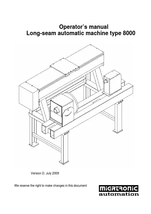
Operator’s manualLong-seam automatic machine type 8000Version D. July 2009We reserve the right to make changes in this documentContents: PageCHAPTER 1: EU DECLARATION OF CONFORMITY (2)CHAPTER 2: GENERAL (3)CHAPTER 3: SAFETY ADVICE AND NOTICES (4)PERSONAL SAFETY (4)Applications: (5)Removal of safety devices: (5)Correct placement of work pieces: (5)CHAPTER 4: HOW THE MACHINE WORKS: (6)Sketch of the long-seam automatic machine: (6)Starting and stopping the machine: (7)Failure during start-up, operation or shut-down: (8)Maintenance: (9)Basic precautions: (9)Maintenance checklist: (11)Storage of this operator’s manual: (12)CHAPTER 5: ASSEMBLY AND DISASSEMBLY (13)Design and construction of the long-seam automatic welding machine: (13)Set-up: (14)Disassembly: (16)CHAPTER 6: TECHNICAL DATA: (17)External connections: (18)List of replacement parts – long-seam automatic machine (21)IMPORTANT SAFETY NOTICEAlways read the operator’s manual carefully and thoroughly before operating the machine. When working, always bear in the mind the directions and safety instructions. When installing and operating the machine, read and follow the safety directions stated in the chapter of this operator’s manual entitled SAFETY ADVICE AND NOTICES.This operator’s manual must always be available to the persons installing, operating and servicing the machine.Chapter 1: EU Declaration of ConformityManufacturerCompany name: Migatronic Automation A/SAddress: Knøsgaardvej 112DK-9440 Aabybro, DenmarkTelephone: (+45) 96 96 27 00Internet: www.migatronic-automation.dkhereby declares thatThe machineMake: Long-seam automatic welding machineType: 8000has been manufactured in compliance with the provisions of the COUNCIL DIRECTIVE of 14 June 1989 on mutual approximation of the laws of the member states on machines (89/392/EEC as amended by 91/368/EEC and 93/44/EEC) with special reference to annexe 1 of the Directive on essential health and safety requirements in connection with the design and manufacture of machines (cf. Statutory Order of the Danish Working Environment Authority (Arbejdstilsynet) No. 561 of 24 June 1994).25/8-2006 Keld KjeldgaardDate SignatureChapter 2: GeneralThe type 8000 long-seam automatic machine has been designed for the automatic welding of straight seams using either MIG/MAG or TIG/PLASMA welding methods.It comes fitted as standard with 2-way adjustable gun mounting, but can also come supplied with automatic gun lift, as well as automatic stop/start of the root gas.If power sources are used in connection with the machine, read the operating manual of the power source prior to starting work.Chapter 3: Safety advice and noticesPERSONAL SAFETYLight and heat emissionA welding arc emits radiation which is damaging to the human eye. Even short-term exposure to this radiation can cause permanent damage. Your eyes must be protected against powerful infraredradiation, as well as visible and ultraviolet light by using suitableradiation protection glass fitted in your welding helmet. Your skin may also be damaged by this radiation. Radiation can cause serious burns. Protect your skin by wearing the helmet, full-body working overalls and gloves. Warn other people in the vicinity of the welding area of the danger of radiation and flying sparks. If possible, screen the workplace off from the surrounding environment. Together with flying sparks, heat radiation from the electric arc and the molten pool constitute a fire risk. For this reason, do not perform welding in the vicinity of flammable materials. Do not put the torch down without first extinguishing the flame. Your working clothes must not contain easily flammable materials or have creases or open pockets which may collect sparks. Wear a fireproof apron if appropriate. After completion of the work, switch off at all socket outlets or at the main valve, and depressurize hose couplings.Welding fumesThe smoke and fumes generated by the welding process are hazardous to health. Therefore extraction systems must be installed in such a way that the fumes which arise during welding are removedeffectively. When fumes from degreasing agents are acted on byultraviolet radiation from the electric arc, this may produce very toxic phosgene gas. For this reason, all dissolvents, degreasing agents and other potential sources of such fumes must be kept away from the welding area. Avoid inhaling welding fumes and gases. Use benches with extraction or other extraction systems for removal of welding fumes and gases. Use oxygen masks if no such effective extraction system is possible.ElectricityAvoid making contact with live components.The voltages used in connection with welding are not high enough to pose a risk of serious electric shock. However, minor electric shocksmay result from damp overalls and the like, and these can frighten the welder, so potentially posing an indirect safety hazard. In particular, HFhigh-voltage ignition in TIG and PLASMA welding can generate powerful shocks and cause minor burns under the skin. Contact with live welding parts should therefore be avoided as far as possible. Always ensure that cable insulation, as well as insulation on the torch and machine pin and socket connectors, is fully intact. Always wear dry leather gloves, dry overalls and dry footwear. Furthermore, keep cables, torches and the welding machine itself dry at all times. It is important that the machine’s connections have been set up according to the applicable regulations (power cables, fuses and safety conductor/earth lead). Do not open the machine to expose the live parts. Service and maintenance requiring access to live parts of the machine must only be undertaken by properly qualified personnel. Never leave a dismantled machine connected to the mains supply.Applications:- TIG welding hoses (live cables) and torches must not be placed on the electronic control box.- Do not exceed the maximum dimensions for work pieces laid down in the operator’s manual.- The machine/equipment may only be run by operators who have been trained in its use and who have also worked through the operator’s manual.Removal of safety devices:- Safety devices may not be disabled or removed while the machine is in an operating condition.Correct placement of work pieces:- Prior to starting work with the machine, the operator must ensure that the work piece has been correctly placed and properly secured.Chapter 4: How the machine works:Sketch of the long-seam automatic machine:Type: 1100 1650 2000 2500 3000 3500 4000 5000 Dimensionsmm a 1585 2160 2540 3040 3560 4000 4510 5010 mm b 265 265 265 265 265 265 265 265 mm c 600 600 600 600 600 600 600 600 mm d 800 800 800 800 800 800 800 800 mm h 1240 1240 1240 1240 1240 1240 1240 1240 mm i 1760 2260 2760 3260 3760 4260 4760 5260 Wkpce1100 1650 2000 2500 3000 3500 4000 4500 length mmStarting and stopping the machine:Use the cross-supports (A) to set the welding gun to the correct position. On how to set the welding speed, pre-welding time, post-welding time etc., refer to the operator’s manual for the 4005 control system.Adjust the inductive sensors on the rails to the desired positions (see “Set-up” in chapter 5).For welding with cold wire feed, set the wire speed on the type KT4 (B) cold wire feeding unit. Refer to the separate operator’s manual for this. Set the switch on type 4005 control systems to manual or automatic return. Activate the start button on type 4005 control systems and perform the welding using the programmed data.Failure during start-up, operation or shut-down:If monitoring of the electric arc (arc control) and welding have been activated, the automatic machine will not start until the electric arc has been established.While the machine is in this waiting mode, the operator must be aware that it may start once the electric arc is started.Maintenance:Regular maintenance is important.This ensures:* A long service life for the machine* Safety* Operational reliabilityMany of the maintenance tasks are simple for the operator to perform himself and require just a little mechanical skill and a few tools. These tasks are described below. However, note that some maintenance tasks require special tools and expertise. Such tasks should be given to qualified Migatronic employees. Even if you are an experienced DIY-mechanic, we recommend that you hand over repairs and maintenance to Migatronic Automation A/S.Basic precautions:- Disconnect all mains power before working on electricalinstallations or components.- Make sure you keep the work area clean and tidy.- Disconnect the power and air supply to the machine when it isnot in use or is left unattended.DAILY CHECKS BEFORE START-UPInspect the control system:A. Check that all power and fuse lamps light up.B. Ensure that the plug is properly inserted in the rear.C. Perform a cycle without doing any welding.Check mains leads, earth cables, air and gas hosesA. Check for external damage.B. Check for loose connections, elements or leaks.Welding control:Weld a work piece and compare to the one you retained from the same time the day before. If everything is OK, retain the piece you just welded for start-up on the following day.WEEKLY CHECK-UPClean all important surfaces using compressed air and lubricate sparingly with machine oil. Sign the maintenance checklist.MONTHLY CHECK-UPIn addition to the weekly inspection, check all nuts and Unbrako screws – especially on ball bearings, gun mounting and roll guides.Release carbon in the carbon holder (if any is fitted) and clean with compressed air, checking the carbon length.Check gear motors for leakage in gear gaskets and check wires. Check for play in main bearings.Clean the power sources internally (remember to remove the mains lead!). Sign the maintenance checklist.Maintenance checklist:Date Weekly check-up Monthly check-up Comments Init.Storage of this operator’s manual:Keep this operator’s manual in a place accessible at all times to operators, maintenance personnel and repairmen.Chapter 5: Assembly and disassemblyDesign and construction of the long-seam automatic welding machine:The machine is constructed to include carriage (A) which runs on rails on smooth-running roll guides, which are fitted on a robust RHS (B).The propulsion is provided by means of an electronically-controlled gear motor, which pulls the carriage via a toothed belt. Carriage engagement on the toothed belt can be released using a simple grip (C) for rapid relocation of the carriage. A welding gun and control system (D) are mounted on the carriage and the same is ready for the mounting of MIG/MAG or TIG wire feed.The machine is supplied as standard with a 2-way adjustable gun mounting (E).Set-up:Rear of control systemSensors / valves MotorStart welding machineWelding machine earthcableTo move/adjust the inductive sensors, turn the hand-clips (A) a quarter turn. This allows you to then flip the shielding down. Warning! Disconnect all mains power before flipping the shielding down.Working sensor – leftWorking sensor – rightEnd stop sensor – leftEnd stop sensor – rightThe illustration above shows the rails without shielding. After final adjustment, flip the shielding into place again.Warning!Do not leave the long-seam automatic machine in a dismantled condition.Disassembly:The old machine contains reusable parts.For this reason, do not send your automatic machine to the nearest tip; instead, contact your local council or an auto or scrap dealer about the possibility of reusing parts. Disconnect all external connections (electrical, air etc.) before disassembly.Chapter 6: Technical data:Type: 1100 1650 2000 2500 3000 3500 4000 5000 Dimensionsmm a 1585 2160 2540 3040 3560 4000 4510 5010 mm b 265 265 265 265 265 265 265 265 mm c 600 600 600 600 600 600 600 600 mm d 800 800 800 800 800 800 800 800 mm h 1240 1240 1240 1240 1240 1240 1240 1240 mm i 1760 2260 2760 3260 3760 4260 4760 5260 Wkpce1100 1650 2000 2500 3000 3500 4000 4500 length mm18 External connections:1920Please note that some part in this diagramme are mounted as options, and are not standard.List of replacement parts – long-seam automatic machinePos. no. Description Article number1 Unbrako screw M8x80 40310880-12 Toothed belt pulley 47419422-13 Seeger-A-ring 42510020-14 Shaft for toothed belt pulley. 25403005-15 Ball bearing 44166204-16 End stop sensor – left 17100809-17 Working sensor – left 17100809-18 Guide rail 45032049-19 Toothed belt type 1100Toothed belt type 1650Toothed belt type 2000Toothed belt type 2500Toothed belt type 3000Toothed belt type 3500Toothed belt type 4000Toothed belt type 4500 47041250-1 47041700-1 47042000-1 47042400-1 47042800-1 47043150-1 47043550-1 47043950-110 Carriage 45032040-111 Key fitting for sensor 27111002-112 Contact lever 45080032-113 Working sensor – right 17100809-114 End stop sensor – right 17100809-115 The engine and gearbox, depending on speedMotor 0.25 kW / 1350 rpm Gear i = 240Motor 0.12 kW / 660 rpm Gear i = 300 (TIG / Plasma) Gear i = 114 (MIG / MAG) 17290070-1 17290071-1 17290073-1 17290072-1 17290074-116 Taper lock bushing 46341526-1。
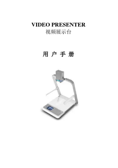
VIDEO PRESENTER视频展示台用户手册视频展示台用户手册简介欢迎使用高科视频展示台。
视频展示台是一种图像采集设备,需要通过与外部输入、输出设备的配套使用,比如多媒体投影机、大屏幕背投电视、普通电视机、液晶监视器等等,是专门为用户在显示终端上演示实物、文本、图片而开发设计技的产品。
在使用视频展示台前,请仔细阅读该手册,并妥善加以保管以备日后作为参考之用。
目录第一章产品概述 (3)1.1产品描述 (3)1.1.1 装箱附件清单 (3)1.1.2 产品部件名称(其他外形类似) (3)1.2产品外观与参数 (4)1.2.1产品外观 (4)1.2.2产品接口参数 (4)第二章视频展台使用方法 (5)2.1 连接及操作方法 (5)2.2操作面板按键/遥控器使用说明 (8)2.3 232应用说明 (10)2.3.1 软件安装须知 (10)2.3.2 软件安装步骤 (11)2.3.3 硬件安装 (14)2.3.4 使用软件控制展台 (14)2.3.5 软件的卸载 (14)2.4 USB使用说明 (15)第三章常见故障维修指南 (18)3.1 维修指南 (18)第四章产品申明 (19)4.1 保修说明 (19)4.2 特别申明 (19)第一章产品概述1.1产品描述1.1.1 装箱附件清单打开包装箱,拿出主机和附件,检查下列部件是否齐全1 数码视频展示台 1 台2 交流电源线 1 根3 RGB信号线 1 根4 本用户手册 1 份5 电源适配器 1 只5 RS232连接线(选配) 1 根6 USB线(选配) 1 根7 红外遥控器(选配) 1 个8 应用光盘CD(选配) 1 张1.1.2 产品部件名称(其他外形类似)○1摄像机外壳,内部装备高解析度摄像机和镜头○2镜头杆支架及灯体○3侧灯及灯臂○4操作面板○5演示台面○6红外接收窗○5○1○2○4○3○61.2产品外观与参数1.2.1产品外观(图片仅供参考,以实物为准)1.2.2产品接口参数①输入端口VGA×2 AV×1 MIC×1(选配)②输出端口VGA×2 AV×2③控制端口USB×1 RS232×1 SD读卡×1(选配) LCD×1(选配)第二章视频展台使用方法2.1 连接及操作方法1、开机前根据需要将展示台接口与外围设备连接好,请参考下列示意图连接设备:(部分机型接口有略微差异,均参考此图使用)(展台基本连接示意图)侧边插口10 7 11 12 13(图片仅供参考,以实物为准)1、VGA-OUT1/VGAOUT2:连接显示设备的VGA接口,如投影机,显示器等2、VGA-IN1/VGA-IN2:连接外部VGA信号源3、USB:连接电脑USB接口4、RS232:连接电脑串口5、SVIDEO:S-VIDEO信号输出,用S端子线连接显示设备6、V-IN:RCA视频输入口7、A-IN:音频输入口8、A-OUT:音频输出口9、V-OUT:RCA视频输出口10、MIC:麦克风输入口11、USBPORT:USB接口,用于读卡内容的输出(与电脑USB端连接)12、SD-CARD:SD卡插槽13、CF-CARD:CF卡插槽14、DC12V:12V外置电源接口2、准备使用视频展示台(参考主机外观图):步骤一轻压演示台面,拉起支撑杆至预定位置;步骤三转动摄像头,调节其角度至垂直演示台面,取下镜头盖。
咖玛变频器说明书8000第一章:产品概述咖玛变频器8000是一款高性能的变频器,适用于各类电机的驱动控制。
它采用先进的变频控制技术,具有可靠稳定、高效节能、输出精度高等特点,广泛应用于工业控制领域。
第二章:产品特点1. 高效节能:咖玛变频器8000采用先进的PWM技术,通过调整电机的转速来实现负载的需要,从而达到节能的目的。
相比传统的调速方式,能够显著降低能耗。
2. 稳定可靠:咖玛变频器8000具有良好的抗干扰能力,可有效降低外界电磁干扰对电机的影响,保证系统的稳定运行。
同时,采用了过流、过压、过载等保护功能,确保设备的安全运行。
3. 输出精度高:咖玛变频器8000采用高精度的数字控制技术,可实现对电机转速的精确控制,满足不同应用场景的需求,提高生产效率。
4. 维护方便:咖玛变频器8000具有自诊断功能,能够实时监测设备的运行状态,并在故障出现时提供详细的报警信息,方便用户进行故障排除和维护。
第三章:产品参数1. 输入电压:220V/380V/440V等2. 输出电压:0-输入电压3. 额定功率:根据不同型号而定4. 控制方式:V/F控制、矢量控制等5. 频率范围:0-400Hz6. 过载能力:150%额定电流持续1分钟7. 环境温度:-10℃~+40℃8. 保护等级:IP20/IP54等第四章:安装与调试1. 安装:将咖玛变频器8000固定在平稳的地方,确保通风良好。
接线时注意电源和电机的连接正确无误。
2. 参数设置:根据实际需求,设置变频器的工作参数,如输入电压、频率范围、过载保护等。
3. 调试:在设置完参数后,进行逐步调试,确保系统正常工作。
注意观察设备的运行情况,如有异常及时处理。
第五章:使用与维护1. 使用注意事项:使用时请注意防水、防尘、防湿等措施,避免设备受损或故障。
2. 维护保养:定期清洁设备表面,注意检查电缆连接是否松动,及时更换损坏的元件。
3. 故障排除:在设备故障时,请通过判断故障指示灯、查看故障代码等方式,进行故障排除。

8000系列视频解码器说明书_视频解码器使用说明书网络视频解码器使用手册声明本手册可能在某些技术细节方面描述不够准确或存在印刷错误,假如您在使用过程中按照使用手册无法解决问题时,请致电我公司技术部垂询相关操作方法。
本手册的容将做不定期的更新,恕不另行通知。
装箱清单1.视频解码器一台2.DC12V电源适配器一只3.用户使用手册一本4.随机光盘一5.合格证以及保修卡一目录1产品简介 (4)1.1产品简介 (4)1.2功能简介 (4)1.3技术规格 (4)2外观与说明 (5)3设备安装 (5)4. 功能操作说明 (6)4.1 初始化菜单说明 (6)4.2 主菜单说明 (6)4.3连接菜单 (7)4.4地址薄菜单 (8)4.5循环连接菜单 (8)4.6循环设置菜单 (9)4.7添加循环服务器菜单界面 (9)4.8系统设置菜单界面 (10)4.9 网络设置菜单界面 (11)4.10 MAC修改菜单界面 (12)4.11 系统参数菜单界面 (12)4.12 云台控制菜单界面 (13)4.13 报警状态菜单界面 (14)4.14 报警设置菜单界面 (15)5 升级软件 (17)6常见问题解答 (17)附录A 球型摄像机键盘的使用 (17)1产品简介1.1产品简介感您使用本公司产品,我们将向您提供最好的服务。
网络视频解码器是基于嵌入式的视频处理、控制及传输设备,其核心是运行实时操作系统的嵌入式计算机和高性能视频DSP。
无需PC 平台,直接将数字音视频数据从网络接收解码后直接输出到电视墙,同时能与编码器进行语音对讲。
嵌GUI,支持遥控器和键盘,操作方便、简单。
1.2功能简介标准MPEG-4视频解码格式标准MP3音频解码格式。
支持1路4CIF、2CIF、HCIF、CIF分辨率解码双向语音对讲支持键盘接入、矩阵控制器等控制设备,提供SDK二次开发,方便集中管理支持通道控制及可编程循环连接,可灵活组成数字矩阵成本低,性能稳定的模拟输出解决方案2 外观与说明电源输入:DC12V 、1.5A音频输出接口:线路电平,非平衡,单声道,RCA 接口 ? 音频输入接口:麦克风输入,非平衡,单声道,RCA 接口视频输出接口:PAL/NTSC 制式,复合视频:1Vp-p/75Ω,BNC 接口 ? RS485:网络(LAN)接口 ? RST 复位3 设备安装a. 将视频解码器连接入你的网络或者用交叉网线直接连接到PC。
P A8000C N C系统操作手册(第一版)声明操作手册所包含的内容均受到版权法的保护,未经深圳大族彼岸数字控制软件技术有限公司的批准,任何组织和个人不得以任何手段和形式对其进行复制、存于数据库或检索系统。
是深圳大族彼岸数字控制软件技术有限公司的注册商标并对其享有独占使用、许可使用、转让、续展等各项法定权利,未经深圳大族彼岸数字控制软件技术有限公司书面许可,任何组织或个人不得在商品上使用相同或类似的商标。
HAN’S PA不承担由于没有正确使用本手册和本产品的情况下,所造成的一切间接、直接或附带的损失或人身伤害。
在未经许可的情况下,不得擅自更改本产品的硬件、软件,或者进行二次开发。
由此造成的法律纠纷,本公司概不负责。
本技术数据由 HAN’S PA 编制。
公司有权力在事先不通知客户的情况下,修改本手册。
客户如有疑问的地方请直接联系客户服务热线:9或查询公司网站上技术资料公司网址:服务邮箱:pa service@公司地址:深圳市南山区高新技术产业园北区北环大道大族激光大厦目录1 操作人员参考概要 (3)1.1 预览 (3)1.2 开机 (3)2.入门 (4)2.1综述 (4)2.2漫游(手动模式) (4)2.3 手动数据输入(MDI模式) (5)2.4运行程序段(自动模式) (7)3 HMI的概况 (8)3.1综述 (8)3.2 手动菜单 (10)3.3自动菜单 (11)3.4 数据菜单 (12)3.5信息菜单 (13)3.6系统菜单 (14)3.7 设置菜单 (15)4手动 (16)4.1初始画面 (16)4.2连续进给 (17)4.3增量进给 (18)5 自动 (18)5.1初始界面 (18)5.2选择工件程序 (19)5.3 选择程序号 (20)5.4程序块的选择 (20)5.5程序执行1 (21)5.6 手动数据输入 (22)5.7程序执行2 (22)6.数据 (23)6.1初始界面 (23)6.2跳转 (24)6.3 菜单 (25)6.4查看 (26)6.5 修改 (26)7. 附加功能 (27)7.1 信息菜单 (27)7.2设置菜单 (28)1 操作人员参考概要1.1 预览本手册集中讲述PA 8000系统的操作与功能(PA8000系统是一个开放式系统),手册的目的是为了让操作者更熟悉本CNC系统。
嘉兴市佳乐科仪有限企业-JR8000系列产品目录第1章前言.....................................................1第2章概括. (2)开箱检查············································· (2)产品搬运············································· (2)产品保存············································· (2)产品保修············································· (2)铭牌说明············································· (3)第安全注意·········································3章事项··4安装······················································4配线······················································5送电······················································6保护······················································6其余······················································6对于机械负载··········································7对于变频器 (8)第4章产品标准规格··········································11产品个别规格··················· (11)产品技术指标··················· (12)第安·························5章装·····························14安装环境····························· (14)安装方向与空间 (14)变频器外形尺寸······························ (15)第6章配线......................................................17主回路配线表示图. (17)接线端子说明图······························ (18)基本连结图····························· (27)主电路配用设备、电线尺寸 (28)第7章操作面板及操作方法····························· (31)I嘉兴市佳乐科仪有限企业-JR8000系列产品第8章简单运行 (34)运行前检查和准备······························ (34)试运行·················································34第9章详尽功能介绍······························ (36)第10章串行通信...........................................101第11章故障对策. (102)故障诊疗和纠正举措 (102)代码比较表 (103)报警显示和解说 (106)电动机故障和纠正举措 (107)第12章养护与保护····························· (110)基本保护和检查方法 (110)按期检查项目······································110第13章周边设备采纳及配置·············· (112)制动电阻配置表·················· (112)第14章应用事例····························· (114)外面电位器的使用····························· (114)内控多段速运行················· (11)4多台变频器连动问题(两种方式)······· (116)工频/变频切换运行·······························119恒压供水 (120)一般变频器的设置所考虑的参数 (121)第15章功能参数简表 (122)II嘉兴市佳乐科仪有限企业-JR8000系列产品第1章前言特别感谢您使用JR8000系列通用变频器!JR8000系列变频器是采纳先进的电力电子技术,由靠谱的元件,优秀的资料精心制造而成。
PA8000PLC中文手册此手册供开放式架构数控体系PA 8000的PLC编程人员参考应用,编程人员在进行PLC编程之前请细心扫瞄本手册。
手册中将介绍若何应用体系中自带的PLC编程对象进行编程,同时介绍编程指令合格局等,手册中的编程格局为ST,其它的编程格局不具体介绍。
最后将以一铣床的PLC法度榜样为例加深对法度榜样的明白得为了使手册加倍通俗易明白,手册中并没有介绍所有的与PLC相干的内容,用户如有须要可向机床制造商索取专门的介绍材料。
欲望调试人员能经由过程对本手册的扫瞄更快地闇练PLC编程。
PLC-1131-S3为PLC编程供给了一个完美的情形,为PLC法度榜样员处理各类法度榜样供给了一个简单而又功能强大年夜的门路,它的编程和调试基于完美的情形和高等编程说话(类似与Visual C++)。
2.1PLC-1131-3 DS功能简介工程文件的构造:工程文件的后缀名为pro,在新工程中建立的第一个法度榜样构造单位(Program Organization Unit)将被主动定名为PLC_PRG,那个法度榜样构造单位就类似于C说话中的主法度榜样。
在PLC_PRG中能够调用各类函数及功能块,而函数和功能块都属于法度榜样构造单位。
PLC-1131-3 DS能够或许区分在同一工程中的不合对象:法度榜样构造单位(POU)数据类型(data types)资本(resources)工程的设置:1) 起首应当设置PLC的输入输出以包督工程中应用的地址的精确性。
2)接着建立解决问题的法度榜样构造单位3) 选择恰当的说话编写法度榜样4) 写好法度榜样之后,对法度榜样进行编译去除法度榜样中的所出缺点。
工程的测试:当工程之中的所出缺点被去除之后激活仿真模式,确实是与仿真PLC连接,与此同时将工程下载到PLC中,如许PLC-1131-3 DS就处于在线方法了。
现在能以恰当的次序测试工程了,手动改变输入变量的值,不雅察输出是否精确。
DMA 8000使用手册目录DMA 8000控制程序----------------------------------------------------------------------------------------------------3 DMA 8000实验方法----------------------------------------------------------------------------------------------------8 DMA 8000实验数据相关说明------------------------------------------------------------------------------------32 DMA 8000仪器校正---------------------------------------------------------------------------------------------------37 DMA 8000软件安装---------------------------------------------------------------------------------------------------40 TMA模式应用和时温等效----------------------------------------------------------------------------------------58 附录-------------------------------------------------------------------------------------------------------------------------81DMA 8000控制程序软件结构DMA 8000控制软件融合了Microsoft Office Excel技术,所有的实验数据以及方法编辑都可以在Excel表格中进行操作。
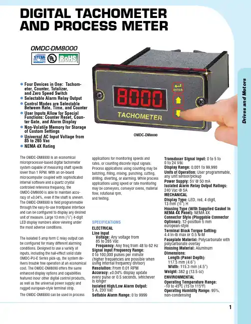
1D r i v e s a n d M o t o r sDigital tachometer anD Process meterl F our Devices in One: Tachom-eter, Counter, Totalizer, and Zero Speed Switchl Selectable Alarm Relay Output l C ontrol Modes are Selectable Between Rate, Time, and Counter l U ser Inputs Allow for Special Functions: Counter Reset, Coun-ter Gate, and Alarm Display l N on-Volatile Memory for Storage of Custom Settings l U niversal AC Input Voltage from 85 to 265 Vac l NEMA 4X RatingThe OMDC-DM8000 is an economical microprocessor-based digital tachometer system capable of measuring shaft speeds lower than 1 RPM. With an on-boardmicrocomputer coupled with sophisticated internal software and a quartz crystal controlled reference frequency, the OMDC-DM8000 is able to maintain accu-racy of ±0.04%, even if the shaft is uneven. The OMDC-DM8000 is field programmable through the easy-to-use frontpanel interface and can be configured to display any desired unit of measure. Large 13 mm (1⁄2”) 4-digit LED display numbers allow viewing under the most adverse conditions.The isolated 5 amp form C relay output can be configured for many different alarming conditions. Designed to use a variety of inputs, including the hall-effect solid state OMDC-PU-E Series pick-up, the system de-livers trouble free operation at an economical cost. The OMDC-DM8000 offers the same enhanced display options and capabilities featured inour other digital control products, as well as the universal power supply and rugged european-style terminal strip.The OMDC-DM8000 can be used in processapplications for monitoring speeds and rates, or counting discrete input signals. Process applications using counting may be batching, filling, mixing, punching, cutting, drilling, diverting, or alarming. While process applications using speed or rate monitoring may be conveyors, conveyor ovens, material flow, rotational rpm, and testing.OMDC-DM8000SpECIFICATIONS ElECTRICAl line InputVoltage: Any voltage from 85 to 265 VacFrequency: Any freq from 48 to 62 Hz Signal Input Frequency Range: 0 to 100,000 pulses per minute(higher frequencies are possible when using internal frequency divisor)Resolution: From 0.01 RPMAccuracy: ±0.04% display update every pulse or 0.5 seconds, whichever is longerIsolated High/low Alarm Output: 5 A, 230 VacSettable Alarm Range: 0 to 9999Transducer Signal Input: 0 to 5 to 0 to 24 VdcDisplay Range: 0.001 to 99,990Units of Operation: User programmable, any unit sensor/pickuppower Supply: 5V @ 50 mAIsolated Alarm Relay Output Ratings: 240 Vac @ 5A MECHANICAlDisplay Type: LED, red, 4 digit, 13 mm (½”) HHousing Type (With Supplied Gasket in NEMA 4X panel): NEMA 4XConnector Style (pluggable Connector Optional): 12-position 5 mm european-styleTerminal Block Torque Setting: 4.4 in-lb max or 0.5 N-MFaceplate Material: Polycarbonate with polycarbonate overlayHousing Material: Aluminum Dimensions:length (panel Depth): 117.5 mm (4.6”)W idth: 115.3 mm (4.5”)Weight: 382 g (13.5 oz)ENVIRONMENTAlOperating Temperature Range: -10 to 45ºC (15 to 115ºF)Operating Humidity Range: 95%, non-condensingOMDC-DM80002Cut-Out and Mounting Dimensions: mm (in)127(5)117.4(4.6)58.2(2.3)41.9(1.7)TachIte mValu PageTACHOMETERENTER101.6 (4)101.6 (4)HOUSING DEPTH 117.6 (4.6)PANEL CUT-OUTOMDC-DM800092 (3.6)3.6(0.1) x222.4 (0.9)45 (1.8)Bi-directional Incremental Position DisplayCoupling to Chain DriveTacht e malu PageTACHOMETERENTER263.4Drive Train Specs:40 revolutions = 3.5"of platform motionOMDC-PU-20EQUAD or equivalentOMDC-DM8000 Meter530BRE-36M ControlON OFFFWD REVConnect to CouplingLinear-Motion SystemPlatformDescription:A system is needed which will track the position of a bi-directional linear-motion platform and allow the user to select a home or zero position. The display should read in inches and indicate the position of the platform at all times.ApplICATIONS3D r i v e s a n d M o t o r sD-3Wiring Diagram:P1-1P1-2P1-3P1-4P1-5P1-6P1-7P1-8OMDC-DM8000P1-9P1-10P1-11P1-12Not Used Not Used Not Used }AC Line Input 85 to 265 Vac, 50 to 60 Hz2 AmpOMDC-PU-20EQUADblack white red NC1C1NO1N L COM +5V S1S2NC2C2NO2Not Used Not Used Not Used brownor equivalentConveyor Oven Time Monitor with Over-Heating AlarmHeat Source TACHOMETER18:402 3 or other Motor ControlTunnel OvenOMDC-P -20 or e uivalentNon- educed haftear MotorCoupling to Chain DriveConnect to CouplingOMDC-DM 000 MeterDescription:An oven monitor displaying the “tunnel” time in minutes and seconds. The tunnel time is defined as the time it takesfor the heated object on the conveyor to travel from point A to piont B in the application diagram below. A visual indicator should activate if the tunnel time rises above a preset imit of 22 minutes and 30 seconds which could cause overheating of the processed material. The indicator should automatically reset when the tunnel time returns to the normal operating range. For ease of use, the display should be averaged over a period of 1 second.A BDrive Train pecs:12 0 PM at non-reduced motor shaft e uates to minutes and 1 seconds of tunnel timeParaMeter COnfiguratiOn ParaMeter Value nOtes 10 5 Up/down counter mode 20 35 Because the initial values were 40 revolutions per 3.5” of platform motion, each is multiplied by 10 to give an even number to increase accuracy since the displays can be programmed in whole numbers. Additionally, because of the decimal point position, the display reference is multiplied by 10 to generate the proper display format. Without the second multiplication by 10, the display would only read 3.5" when the driver motor turned 400 revolutions. 21 400 In count mode, the reference RPM is set in revolutions. 400 has been entered here to represent 40 revolutions and the disply reference has also been multiplied by 10 to yeild the whole numbers. 22 10 Pulses per revolution of shaft encoder or pick-up is 10 PPM 25 3 Decimal point position set to XXX.X on displayWIRING DIAGRAMApplICATIONSOrdering Example: OMDC-DM800, digital tachometer with alarm relay output. 4。
saj8000变频说明书saj8000变频说明书亮。
? REV:当变频器处于反转运行时,该指示灯亮。
(3)监视运行参数变频器在运行过程中,按一次“DATA”键,再按“▲”或“▼”键选择观看运行电流或运行频率。
Hz灯亮表示频率,I灯亮表示电流。
(4)查看故障记录变频器在运行过程中或待机状态下,按两次“PRGM”键,再按“▲”或“▼”键可逐次观看最近4次故障记录。
观看完后按“DATA”键,变频器复位。
( 5)参数修改步骤变频器在待机状态下:步骤1:按“PRGM”键,变频器显示“Fxxx”,“xxx”为参数号。
步骤2:按“▲”或“▼”键选择所需要参数码,按“STOPRESET”键可移动光标位置。
步骤3:按“RDWT”键读取该参数的内容。
步骤4:按“▲”或“▼”键修改该参数值,按“STOPRESET”键可以移动光标位置。
步骤5:按“RDWT”键把数值设定。
如欲修改其它参数,请重复步骤1~5即可。
备注:要修改REWT类型的参数时必须先把F096设为“1”。
2、操作范例(1)修改参数(将F002的参数值从10S改为5S)。
变频器通电后,键盘显示“0.00”,按一次“PRGM”键,键盘显示“F000”;按“▲”键调到“F002”,按一次“RDWT”键,读出该参数内容,键盘显示“10.0”,按“▼”键把“10”改为“5”,在按一次“EDWT”键设定,然后按“DATA”键即可。
(2)变频器参数初始化变频器通电后,键盘显示“0.00”,按一次“PRGM”键,键盘显示“F000”,然后按“▲”键把“F000”调到“F094”,再按一次“RDWT”键,键盘显示“0”,按“▲”键改为“1”,按“RDWT”键设定,再按两次“PRGM”键,键盘显示“0.--”,然后在按一次“STOPRESET”键,变频器开始初始化。
经过三秒钟后变频器初始化结束,键盘显示“0.00”。
备注:①按以上步骤进行参数初始化,如果初始化失败,请查看参数“F095”是否锁定;②按以上步骤初始化,只对“RW”类型的参数有效,要对“FRW”类型的参数进行修改,必须先把“F096”设为“1”。
Installation and Operation ManualKEMPER system 8000 Extraction and filter unit with automatic filtercleaningRef. 80 0505.000 m3/hTable of ContentsA. Application and OperationInformationB. SafetyC. Positioning and installationD. Control panel and self diagnostic control systemD-1Putting Filter unit into operationD-2Message and information of control deviceD-3System Information and malfunctionE. MaintenanceE-1Emptying of dust collecting containerE-2Drain condensateE-3Tensioning of belt-driveF. Technical specifications and data-sheetG. Spare part listH. EC declaration of conformitydiagrammI. WiringAdress listA. Application and OperationKEMPER-Cartridge filters are mainly used for the extraction and filtering of welding smoke, dust and harmful substances created during the process of plasma and flame cutting operations. To capture all these harmful substances the following capture devices are used:●Exhaust hoods●Down-draft tables●Exhaust arms and cranes●Suction nozzlesVia these capturing devices, the polluted air is led into the filter unit through a duct system. Through the air circulation coarse particles are seperated in the first section.The seperation of the polluted air works according to the principle of surface filtration by means of cartridges with Teflonmembrane.This membrane has a very homogeneous pore structure and is permeable to air However, it retains even the smallest particles. Thus the welding smoke is separated at the surface of the filter cartridges. The cleaned air flows up wards inside the filter cartridges and reaches the clean air section of the filter unit. From there it is led to the ventilator and then back to the workroom or via a duct system to atmosphere.Due to the contineous settling of particles on the surface a resistance is set up. Once the allowed air resistance is reached the cleaning process starts automatically. This is done through rotating nozzles by means of compressed air. The compressed air reservoir is installed in the filter aggregate. Through the rotating nozzles the compressed air works from the inside on the whole surface of the respective filter cartridge.The filter cartridges are cleaned individually in turn. Thus permanent running is guaranteed during cleaning Further more, every time the machine is switched off the described cleaning process starts automatically.After the seperated dust has been blown off the cartridges it falls down to the collecting box which is mounted underneath the cartridges. To remove the collecting container it can be lowered very easy by using the compresser air lift.All main functions of the unit are permanently controlled by the electronic control system. The display gives information of Filters, Motors, Airflow and working hours etc. Also it helps to find and avoid possible malfunctions.All information is automatically shown on the cleartext display.InformationB. SafetyCaution:When using electrical devices the following basic safety measuresmust be followed to prevent shock, injury or fire!Read and follow these instructions carefully before using the filter unit!*Keep this Installation and Operation Manual handy.*Read data on Typeplate*Before opening the maintanance door switch off the machine.*Don't use this Filter unit for the extraction of flamable or explosive substances (e.g. solvents).*Don't use this Filter unit for the extraction of explosive dusts (e.g. aluminium powder).*Don't use this Filter unit for the extraction of aggressive substances (e.g. acids). *Don't use the Filter unit without Filter inserts.*Always use original spare parts.*Keep the machine dry.*Connect the machine to power only by authorized electrician.Caution:Check direction of rotation of the ventilatorC. Positioning and installationThe unit can be lifted easily from the shipping palet and brought to site of installation. To carry the unit you should lift it at the outer fork lift bags at the front side of the unit. Furthermore the unit can be lifted by an elevating truck which should be positioned at the recess clearance in the middle of the basic frame of the unit.The unit can be installed and adjusted uprightly at the working station by putting some metal plates under the unit. After this, the ducting has to be connected to the orange panel with the rectangular hole by an adequate transition piece. In case the purified air may not or shall not be led back into the working area, you have to connect a second transition piece and a ducting to outside to the designated outlet opening in the upper sections of the filter unit.The filter unit will be connected to the pressure air supply by means of a pressure reducer and a pressure air filter. To operate the unit you will need pressure air which is clean, dry and free of oil with a pressure of 5 to 6 bar. For this purpose the unit is supplied with a nipple for connection of pressure air to which the pressure air hose (diameter: 9 mm) can be connected.In a final step the unit has to be connected to the power supply system. This should only be undertaken by an autorised electrician to ensure that the input supply voltage is corresponding to the details on the type plate of the machine. Furthermore you have to be sure that the connection of the power supply will be undertaken accordingly. The units for the most current input supply voltages are supplied with a connection plug. This plug can be found in the upper area of the unit at one side. An appropriate coupler will be attached to the plug. The unit can be operated immediately after inserting the power supply plug.D.Control panel and selfdiagnostic systemD-1Putting filter unit into operation1 Cleartext display2 On/Off switchTo switch the machine on and off.3 SERVICE switchShows how many working hours are left before the next service.4 ADDRESS switchShows the adress of the manufacturer (and telephone, telefax and website).5 Conformation switchConfirmation switch (for service)6 SHIFT switchNot needed for normal use of the unit.7 ESC switchNot needed for normal use of the unit.8 ENTER switchConfirmation switch9 Scroll switchTo scroll messages on the displayD-2 Messages and information of control deviceBy use of the control unit with cleartext display the settings and parameters of the unit can be changed or called up. All readings and functions are described below.M A C H I N E O P E R A T I N G B Y I/0-S W I T C HAs soon as the unit is connected to the power and switched on by the main-switch (main switch only at series 9000 units) the display shows this message. Now the unit can be started by using the on/off switch and switched off as well. If the unit is not used for a longer period eg. on weekends, we recommend not to use the main-switch (series 9000) and to keep the machine off-line. Even if the machine is in an off-line modus an after cleaning cycle is started.M A C H I N E O P E R A T I N G B YE X T E R N A L S W I T C HAs an option the unit can be switched on and off via an external on/off switch or a potentional free contact. (For example welding robots, cutting machines etc.) If the unit is equipped with this option and was started by the on/off switch the above message will be shown on the display. As soon as the external switch is connected to the unit it will start up automatically.Programme PointY O U R K E M P E R S Y S T E MO P E R A T E S C O R R E C T L YAfter the machine has been switched on, this message will come up on the display. The control unit will always return to this message from other programme points after approx 3 min. Any operation fault which appear will be shown automatically . By using the scroll function you can get to other programme points.Programme Point 101W O R K.H R S.:000000C L E A N I N G:000000Indicates the total working hours of the machine regarding the operating time of the ventilator and the number of completed cleaning cycles. The number of cleaning cycles indicates the actual cleaning cycles that have been undertaken during operation and also after cleaning cycles after switching of the unit.Programme Point 202C A R T R I D G E F I L T E R T O T A L:0This indicates the number of filter cartridges installed.…SERVICE“ – switchN E X TS E R V I C E I N:1600H R SThis KEMPER filter unit is a unit with vital function and may only be operated unit regarding to certain aspects of reliability. It is regulated by law that the unit has to be checked regularly and necessary maintenance work has to be undertaken. The frequency of maintenance works is depending on the working hours of the unit. This reading indicates how many working hours are left until the next service should be carried out. By pressing the service button again you will get back to the start display.…ADDRESS“ – switchK E M P E R L T DBy pressing this button you are able to read the complete manufacturer address.By using the scroll function the display scrolls down to telephone, telefax, website and the following message.S O F T W.V.:000/B J:M A C H.N R.Indicates which software version was used, when the machine was built, the year of construction and month of delivery and serial number of the machine. If a visit of a service technican is required please pass on the information of that reading to our service department, they can identify the unit by these information.D-3 System information and malfunctionDuring operation the standard reading will change to the following if there are malfunctions.MaintenanceS E R V I C E N E C E S S A R Y0000H R SWith this reading the machine informs the user about an overdue service, which is also regulated by law. Please contact Kemper to make an appointment for the service to be undertaken (contact details see button …Address“). By pressing the …Enter“-Button this reading can be confirmed. The reading will come up after short time. The filter unit will work correctly during this time.MaintenanceS E R V I C E O V E R D U ES I N C E0000H R SWith this message indicates that the overdue maintenance has not been undertaken, yet. This maintenance is regulated by law and essential for the operational safety of the machine. The maintenance should be undertaken directly by our KEMPER service engineers.Malfunction 1E-01M O T O RP R O T E C T I O N F A N This reading informs about a malfunction of the motor protection switch of the fan due to excessive power supply resulting our of changes in voltage or faults in the motor. If the motor potection switch is tripped out, please check if all 3 phases are connected. Please contact Kemper to check the unit if this reading appears again.Malfunction 2E-02R O T A T I N G F A NI N C O R R E C TThe unit has to be connected that way that a right hand rotary field is generated in order to get the full output of the machine. If this rotary field is not generated the above reading is indicated. The correct rotary field can be achieved by changing 2 phases with each other. The electrical connection of the unit may only be undertaken by our service engineers or a qualified electrician. Malfunction 3E-03M O T O R T E M P E R A TT O O H I G HAn optional accessory are temperature sensors in the motor. If the motor is getting too warm the machine switches off automatically and the above reading appears. The motor temperature of the machine is too high and the unit has been switched of because of security aspects. Please contact KEMPER (contact details see button …Adress“).Malfunction 4E-04D U S T C O L L E C T I N GC O N T A I N E R O P E NThe dust collecting container will be lifted upwards to seal the container. If this reading appears the dust collecting container is lifted down. The unit can not be operated in this case and will be switched off or can not be switched on. Lift the container by shifting the hand valve.Malfunction 5E-05C O N T A C T O R O P E R.I N C O R R E C TThe unit controls also the function of the main motor protection switch and the star or delta switch. Appears the above described malfunction, please contact an electrician or the KEMPER service department (contact details see button …Address“).E. MaintenanceE-1 Emptying of the dust collecting containerThe dust collecting container should be emptied regulary. The intervals should be specified with respect to the amount of dust created by the process. If very light dusts are created the intervals should be shorter.To discharge the dust collecting container:●Open the maintenance door of the filter unit●Lower the collecting container by shifting the pneumatic valve to left hand side.The filter unit will switch of automatically. (The pneumatice valve can be found on the left hand side behind the maintenance door.)Danach erscheint folgende Meldung:E-04D U S T C O L L E C T I N GC O N T A I N E R O P E N●Remove the container from the filter unit and close this container with the lidthat has been delivered together with the container and fix it with the toggle tip fastener.Please note:The collected dust has to be recycled according to public regulations.●Put the container back on the pneumatic lift.●Lift the container by shifting the pneumatic valve.Please note:Please pay attention that no objects are between sealing of the container and filter unitThe following reading appears in the display:S W I T C H I N G O N V I AI/0-S W I T C H● Close the maintenance door of the filter unit● Switch the unit on via the 1/0-switchE-2 Drain of condensateThe condensate should be drained regularly every month. The drain valve is located next to the pressure air maintenance unit. Put a suitable container below the drain valve and open the valve. Close the valve after all moister has been drained and only air is puring out of the valve.E-3 Tensioning the belt-drive (not for type 80030)After about 50 working hours the belt-drive of the ventilator needs to be checked and the tension of the belt should be re-adjusted first time. After that approx. every 3 to 4 month the belt drive should be checked. The depth of intendation of the belt between both belt pulleys should be approx. 8 mm at a test force of 11 Newton.Procedure:●Switch the unit off by using the main switch and take the power plug out.●Open the maintenance door of the fan unit.●If the beltdrive is to loose you can tension it by moving the completemotor backwards. The motor is installed on an frame with 4 bolts. Open those bolts and move the motor backwards by using the two adjustment bolts on the motor frame.●Close the maintenance door of the fan unit.●Switch the machine on by using the main switch.F. Technical specification / Data sheetCartridge filter unit Part. no. 80 050 - 2.940 cfm - 5.000 m³/h Customer :Technical specification of the filter unit :Filter surface : 6 cartridges each 10 m2 = 60 m2Filter type :Filtercartridge with PTFE-coating Dimensions of each cartridge :diam. 327 mm x 600 mmRotating nozzles :length 600 mmDimensions of the filter unit :w=1.413 mm x d=1.413 mm x h=2.110 mm Air intake :diam. 355 mm x 1Air outlet :diam. 450 mm x 1Compressed air :5,0 – 6,0 bar; clean, dry and free of oilFan performance : 2.940 cfm or 5.000 m3/h at 2.500 Pa Ventilator type :centrifugal fanMotor performance : 1 x 5,5 kWPower supply : 3 x 400 V, 50 HzAmperage :11,6 AWeight :620 kgDimension of dust collecting container 2 x 34 ltr.X 1 Connection pieces are not included.Alternative:Inlet right sideG.Spare Part List Suction and Filter Unit Type 80050Item Description Part.No.109 0300 1Filtercartridge with PTFE MembraneFiltersurface 10 m², incl. gasket2Filtercartridge without Membrane109 0301For applications with high oil mist content,Filtersurface 12 m², incl. gasket3Motor 230/400 Volt – 5,5 kW130 01764Ventilator RZR 11-0355121 025277 600 000 215Rotation nozzle, complete ,without solenoid valve6Solenoid valve 1“, 24 V, AC128 01407Compressed air fabric tube 1“128 00718Hose clamp 1“115 0020132 0017 9Sparefilter set for compressed airmaintenance unit10Motor protection relais118 029611Contactor118 0250117 0273 12Drive belt SPZ 1287(2 pcs. required)13V-belt pulley- Ventilator 2 x SPZ 125117 014514V-belt pulley – Motor 2 x SPZ 150117 026915Dust collecting container 30 L149 008945Bl.11Bl.+=02-E-498-1-11/380050SPS-STEUERUNGKOMPONENTENErs.d.Ers.f.Zentrale AbsauganlageUrspr.20.Nov.2003GHK NormGepr.Bearb.Datum NameDatum3ŽnderungTD13.8/SPS.1/L13.8/SPS.1/N3.8/PE3I/O SERVICE ADRESS*SHIFTESCSPS.0SIEMENSENTERPE N ML1L+X117PE3SPS.1/L+SPS.1/M119Y1 bis Y6 = MagnetventilY7 = Druckluftwartungseinheit Y8 = Drucklufttank (25 L)Y9 = Sicherheitsventil (7 bar)Y10 = Druckregler Y11 = HandhebelventilY12 = Druckluftbalg Y13 = Druckschalter(Hebevorrichtung f•r Staubsammelbeh…lter)LEGENDEY7Y8Y10RPY9Y11Y13PY12Y6Y5Y4Y3Y2Y1PE2FRONTTšRERDUNG 11PE1GEHŽUSEERDUNG 1Wandger…testeckdose3601231X0PCE.WANDGER.STECK.515-6 1CEE-Kupplung3600268X0MEN.PROTOP15A/5P/6H/400V Elektronisches Motorschutzrelais11802961F5SIE.3RB 1016-1SB0 1Motor-2polig1300176M1LAM.7AA112M02VSicherungsklemme36015581F1PH™. UK6,3-HESIFeinsicherung 6,3 x 32mm / 315mA36015591F1SCH. 6,3X32MM/315MA 1TRANSFORMATOR1180028T1TRAFO.90VA/1XPRIM/2XSECSicherungsklemme36013731F6PH™. UK5-HESI 1Feinsicherung 5 x 20mm / 125mA / Tr…ge3600493F6B™H. 5X20MM/125MASicherungsklemme36015581F2PH™. UK6,3-HESIFeinsicherung 6,3 x 32mm / 315mA36015591F2SCH. 6,3X32MM/315MA 1SPS3601563SPS.0SIE.6ES7 214-1BD21-0XB0 1MAGNETVENTIL1280140Y1IMI.24VAC-1ZOLL 1MAGNETVENTIL1280140Y2IMI.24VAC-1ZOLLMAGNETVENTIL12801401Y3IMI.24VAC-1ZOLLMAGNETVENTIL12801401Y4IMI.24VAC-1ZOLL 1MAGNETVENTIL1280140Y5IMI.24VAC-1ZOLLMAGNETVENTIL12801401Y6IMI.24VAC-1ZOLL 1Sch•tz1180250K1SIE.3RT1015-1AP01Sch•tz11802761K2SIE.3RT1015-1AP02Sch•tz11802761K3SIE.3RT1015-1AP02 1BUCHSE Typ: Binder 7233601229BU.2BIN.723.3POLIG-BUCHSE 1Druckschalter3600777P1RIE.DS40251Spannungsfrequenzwandler3601382SFW.01TRŽ.SFW01Differenzdruckmodul91550000181DDM.1KEM.DDM.1Drehfeldanzeige91550000171DFA.1KEM.DFA.119-polige Sub-D Buchse3601385BU.4CON.9-POL-BUCHSE 1BU.5CON.9-POL-STIFT9-polige Sub-D Stiftstecker3601386BUCHSE Typ: Binder 72336012301BU.3BIN.723.5POLIG-BUCHSE 1BU.3BIN.723.5POLIG 1Y7TIM.DWE25Druckluftwartungseinheit13200151Druckluftbeh…lter1280145Y8KEM.DRB251Druckminderer1320005Y10TIM.DRUCKREGLER 1Sicherheitsventil1670069Y9HERO.SICHERH.VENT.KUGELHAHN10401861Y11END.KUGELHAHNDruckschalter36007771Y13RIE.DS40251BALGZYLINDER1280078Y12ENI.BALGZYLINDER10European Community Declaration of Conformity according to European Community machine standard 89/392/EWG, appendix II AWe herewith confirm that the construction ofKEMPER system 8000Extraction and filter unit with automatic filter cleaningPart-No. 80 050is confirm with the following regulations:91/368/EWG European Community machine standard, appendix I No. 189/336/EWG EMV standard versionApplicable harmonized standards, especiallyEN 292 part 1 and part 2security of machineryEMVG law referring to the electromagnetic consistency of devicesEG 87/404regulation for compressed air reservoirsApplicable national and technical specifications, especiallyVDE 0100construction of power plants with a nominal voltage of up to 1000V VDE 0113electrical equipment of industrial machinesUVV VBG 1general regulationsVreden, 07.07.1998i. V. Dipl.-Ing. M. KönningDeutschland/Germany Frankreich/FranceKEMPER GmbH KEMPER sàrlVon-Siemens-Str. 20 ZI du RiedD-48691 Vreden F-67590 Schweighouse Sur Moder Tel.: 0 25 64/68 - 0 Tel.: 03 88 07 29 80Fax: 0 25 64/68 - 120 Fax: 03 88 07 20 10****************************www.kemper.de www.kemper.frTschechien/Czech Republic Polen/PolenKEMPER spol. s r.o.KEMPER Polska Sp. z o.o.Zděbradská 78Al. Korfantego 2CZ-251 01 Říčany-Jažlovice PL 40-004 KatowiceTel.: 323 616 631***************.plFax: 323 616 .pl**************www.kemper.czNiederlande/Netherlands Großbritannien/Great Britain KEMPER BV KEMPER U. K. Ltd. Hartebroekseweg 58 Venture CourtNL-7141 VE Groenlo Verkoopkantoor Debdale Road / Wellingborough Tel.: 0049-2564-68152Northamptonshire, NN8 5AA Fax: 0049-2564-68120 Tel.: 01327/872909*****************Fax: 01327/872181www.kemper-bv.nl**************.ukUSA Espaňa / SpainKEMPER America KEMPER IBÉRICA, S.L.6659 Peachtree C/ Ferrer y Guardia n°1Industrial Blvd S Local 4 y 5Suite C E-08110 Montcada i Reixac Norcross, GA 30092(Barcelona)Tel.: 770/416 7070Tel.: (93) 572 62 90Fax: 770/416 7306Fax: (93) 572 62 93**************************************** www.kemperiberica.es。
jm8000珈玛系列变频器说明书第一章引言jm8000珈玛系列变频器是一款高性能、多功能的电力控制设备。
本说明书旨在帮助用户了解并正确使用该系列变频器。
本章将介绍变频器的背景和目的,以及本说明书的结构和使用方法。
第二章产品概述2.1 产品特点jm8000珈玛系列变频器具有以下特点:高效节能、调速范围广、控制精度高、响应速度快、可靠性高等。
该系列变频器适用于各种电动机控制场合,广泛应用于工业生产、能源系统、建筑设备等领域。
2.2 产品结构jm8000珈玛系列变频器由电源模块、控制模块、驱动模块和外壳组成。
详细介绍了各个模块的功能和结构,并提供了产品外形尺寸图,以便用户了解变频器的整体结构。
2.3 技术参数本节介绍了jm8000珈玛系列变频器的主要技术参数,包括输入电压、输出电压、额定功率、额定电流、工作温度等。
用户可以根据自己的需求选择合适的型号和规格。
第三章安装与调试3.1 安装要求在本节中,详细介绍了变频器的安装要求,包括安装位置、安装环境、接线方式等。
用户在安装过程中需按照要求进行操作,以确保变频器的正常运行。
3.2 接线方法本节介绍了变频器的接线方法,包括电源接线、电机接线和控制信号接线。
提供了详细的接线图和接线顺序,用户可根据图示进行正确的接线操作。
3.3 调试步骤本节详细介绍了变频器的调试步骤,包括参数设置、运行测试和故障排除等。
用户需按照步骤进行调试,确保变频器的正常工作。
第四章使用与维护4.1 操作方法本节介绍了变频器的操作方法,包括运行控制、速度设定、参数调整等。
用户可根据需求进行相应的操作,实现对电机的精确控制。
4.2 故障排除本节列举了常见故障及解决方法,包括过载保护、短路保护、过热保护等。
用户可根据故障现象进行相应的排查和处理,以保证变频器的正常运行。
4.3 维护保养本节介绍了变频器的维护保养方法,包括定期清洁、环境检查、散热器清理等。
用户需按照要求进行维护保养,以延长变频器的使用寿命。
6000系列数字监控系统使用说明6000系列产品说明第一章系统简介 (2)1.1简介 (2)1. 1. 1系统基本配置要求 (2)1.2系统参数 (3)第二章硬件安装 (3)第三章驱动程序安装 (4)第四章系统程序安装 (4)第五章系统软件功能和操作说明 (5)附录: 常见问题解答: (18)第一章系统简介1.1简介本说明书描述了与6000系列视频压缩卡(简称6000压缩卡)有关的硬件安装、软件安装、系统设置、软件使用等方面的内容,请务必按照说明书的指导进行这些工作,以确保监控系统正常、稳定地运行。
注:1、显示器分辨率设定为1024×768,1280x1024,1440x900。
2、在系统安装完后,在控制面版中的电源选项里将关闭硬盘、关闭监视器和系统待机等选项设置为“从不”。
3、检查所有设备是否存在冲突,对于存在冲突的设备,可以通过调整中断号、内存地址或者重新安装驱动程序等方法来解决。
1.2系统参数视频特性*视频输入:CVBS输入*支持制式:PAL、NTSC*压缩分辨率:352*288(PAL),320*240(NTSC)*单通道帧率:25F/S(PAL),30F/S(NTSC)音频特性*语音输入:语音线路输入*监听采样率:32KHz*录像采样率:8 KHz功能特性硬件符合PCI-Ex 规范,PNP支持使用10bit 梳妆噪声滤波器,视频信号清晰度;使用改进型H264压缩方式,内置数字水印,防止篡改;视频编码标准完全符合H264,音频信号清楚,码流低;支持宽屏显示,智能识别1024x768,1280x1024,1440x900 三种分辨率;支持VGA转电视墙显示方式;支持视频定时遮盖,具有高度监控区域保密性;使用整合式文件结构,系统更加稳定,去除文件打包概念,有断电保存功能录像输出格式可选音视频符合流或单独视频流;单路录像帧率在1-25帧(1-30帧)支持多路同时预览,支持视频预览无级缩放支持压缩流/预览流叠加时钟,多国文字的功能支持音视频的实时同步压缩多区域多灵敏度移动侦测支持静态图像捕捉录像格式全面兼容微软播放器超低功耗设计,板卡结构紧凑,系统稳定第二章硬件安装1、打开机箱,露出主机板和PCI-Ex 插槽。
二.故障代码及解决4-316 Fileter吸油过滤器故障(间隙性出现),需更换吸油过滤器4-322 转印带刮板下方靠门偏码传感器故障(清洁传感器或更换)4-324 黄鼓未装好4-325 红鼓未装好4-326 青鼓未装好4-327 黒鼓未装好4-328 转印带驱动电机运行失败4-329 显影仓驱动马达转动故障4-332 转印带边位置检测失败,(调整IPT位置)6-377 和5V电压有关(前门开关)8-105 纸盒1出纸口卡纸8-110 纸盒2出纸口卡纸8-190 双面纸道卡纸8-193 双面纸道卡纸8-194 双面纸道卡纸8-150 定位组件处卡纸8-160 定位组件出口处卡纸8-170 真空传输带卡纸8-312 转印皮带偏移(调整皮带位置,清洁亮片,传感器)9-343 转印皮带位置错误(调整皮带位置,清洁亮片,传感器)9-344 转印皮带位置错误(调整皮带位置,清洁亮片,传感器)9-354 Y粉仓不下粉9-355 M粉仓不下粉9-356 C粉仓不下粉9-357 K粉仓不下粉9-358 二次转印背辊抬升失败(重置二次转印背辊,清洁传感器,重启打印机)10-105 定影时卡纸(硅油过多,减少硅油量)10-106 定影时卡纸(硅油过多,减少硅油量)10-112 双面翻转器卡纸10-120 双面翻转器卡纸10-357 热辊加热失败(热辊未装好,重装热辊)10-387 辅助加热辊加热失败10-314 定影压带位置偏移(重转压带组件)10-315 定影压带位置偏移(重转压带组件)10-316 压带电机传感问题常用配件及耗材充电电极丝(栅网)Charge Corotron assembly 013R00629感光鼓Drum Module Assembly CT350351鼓芯Drum Assy 01k79323热辊Heating Roller 059k22960一次转印辊1st BTR 059K22611二次转印辊2nd BTR 064k92030布油器Frame Assy Oil 01k59734压带里红色压块Pad Kit 019k07411小蛇皮(定影膜)Pad Sheet 019e57460显影仓内过滤网CC Filter 053k91480IBT清洁刷Belt Cleaner Assy 042k91740IBT清洁刮板Blade Assy Pmma 33k93481CT300010 蓝载体CT300009 黑载体CT300011 黄载体CT300012 黑载体转印带IBT Belt CT10003IBT支架上传送辊Roll Assy-Mob 05910080定影油毡Wick Assy 039k90581压带Fuser Belt 130k87563其它注意问题1.调整双面错位进入步骤:钥匙键(11111)---- Tools pathway---- machine defaults 2 --- alignment adjustment -----Paper tray 1 --- alignment profile1 ----- Lead registration(调整左右错位值)side registration(调整上下错位值)注:在出纸方向,图像太靠下,要调整左右值,按加;图像靠上,按减调整左右值,没有作用时,说明纸张尺寸不符合标准(太短或太长)2.颜色管理a原则上每天要校色,实际中根据情况定,一星期3-4次b校色步骤操作软件中进入:Sever-manage color-Calibrator-点击print(放二纸盒80G纸)-选择Page type(34shorted Patches)-再点击Mcasure-Measure进行校色(步骤略)3.加硅油量不要太多,与油槽颈部平行即可4.常见配件使用寿命(P)鼓:15-30W左右一次转印辊:15万左右载体:30万左右IBT支架上右侧红色辊每10万P转一格换鼓时贴上标签(日期, 当前总P数)IBT下方压纸板需定期清洁换新鼓后要打印200P左右再校色施乐8000编号及售后服务编号:3114421102 电话:8008205146常见图像位置问题及解决1.打印图像有纵向无规则条纹2CM左右(可能出现YMCK四色条纹)主要是光电极丝脏造成的,出现此种情况要清洁电极丝2.打印图像有纵向的形状规则的直细线(颜色不固定)主要是由于显影仓中磁辊载体中杂质或磁辊上刮片有破损,需要打开显影仓,清洁杂质,严重时需更换刮片3.打印品中有颜色的点,位置固定,有规则说明鼓上面对应位置有破损的点,严重时要换鼓4.打印品种有较浅的白点,位置固定(打印单色时明显可见,与周围颜色浅)说明鼓上面对应位置有脏点,清除即可5.打印品上有纵向不规则白点(俗称水印)说明压力带组件有问题,清洁压力带中的膜,更换红色压块,如不行则更换压带6.烧边,常出现打印色块较大文件时调整文件中文件的顺序,先打印色块较大的那面,后打印较浅那面双面都较大色块时,要先打单面,再打另一面(套打)7.打印有废灰,表现:常在纸张上册,CMYK四色都有可能出现主要与鼓面有关系,其他与温度没纸张干燥度,碳粉干燥度有关可根据情况换对应颜色鼓8.打印品呈花斑状点:可考虑是否与载体有关,漏载体会此种问题此故障较严重,可叫工程师来维修9.打印品中有偏黑色的脏点,形状不规则一般由于热辊或辅助加热辊上面有脏点导致的清洁热辊,辅助加热辊10.打印品掉粉,用薄纸,色块较杂(四色墨)会出现;主要是显影不良造成的,在布油器红辊上加少量硅油,换厚纸。
珈玛变频器8000系列说明书
第一章:引言
珈玛变频器8000系列是一款高性能的电力传动设备,广泛应用于各种工业领域。
本说明书旨在为用户提供全面的产品介绍和操作指南,以帮助用户正确使用和维护变频器。
第二章:产品概述
2.1 产品特点
珈玛变频器8000系列采用先进的电力电子技术和控制算法,具有以下特点:
- 高效节能:通过对电机的速度调整,实现能耗的最优化,有效降低能源消耗。
- 稳定可靠:采用先进的控制策略和保护机制,确保设备运行平稳可靠,延长设备寿命。
- 灵活多样:支持多种控制方式和工作模式,适应不同场景和需求。
- 易于安装和维护:结构紧凑,操作简单,可实现远程监控和故障诊断。
2.2 产品型号
珈玛变频器8000系列包括多个型号,涵盖了不同功率和电压等级的需求。
详细的产品型号和参数信息请参见第三章。
第三章:产品参数
3.1 型号说明
珈玛变频器8000系列提供多个型号选择,包括8000-0.4kW、8000-0.75kW、8000-1.5kW等。
每个型号均有相应的输入和输出参数,以满足用户的不同需求。
3.2 输入参数
- 电源电压:AC380V±15%
- 频率范围:50Hz/60Hz±5%
- 输入功率因数:≥0.95
3.3 输出参数
- 输出电压:AC0-380V
- 输出频率范围:0-400Hz
- 输出电流:根据不同型号而定
第四章:安装与调试
4.1 安装要求
- 变频器应安装在通风良好、无腐蚀性气体和粉尘的环境中。
- 安装位置要远离磁场和电磁辐射源,以避免影响设备正常运行。
- 变频器应固定在坚实平稳的基础上,以减少振动和噪音。
4.2 连接与调试
- 连接电源:按照电源电压和频率要求接入电源。
- 连接电机:按照电机接线图连接电机,确保接线正确无误。
- 调试参数:根据实际需求设置变频器的运行参数,如输出频率、电流限制等。
第五章:操作与维护
5.1 启动与停止
- 启动:按下启动按钮,变频器将输出相应频率的电压,使电机正常运行。
- 停止:按下停止按钮,变频器将停止输出电压,电机停止运行。
5.2 故障诊断与维护
- 故障诊断:变频器配备了自动故障诊断系统,能够自动检测并显示故障代码,用户可根据代码查询故障原因和解决方法。
- 维护保养:定期检查变频器的散热器、风扇、接线端子等部件,清除灰尘和杂物,保持设备的良好工作状态。
第六章:技术支持与售后服务
6.1 技术支持
- 在使用过程中遇到问题,用户可通过电话或邮件联系珈玛技术支持团队,获取及时的技术咨询和支持。
6.2 售后服务
- 珈玛提供全面的售后服务,包括设备保修、配件更换、维修等,以确保用户设备的正常运行和维护。
结语
本说明书对珈玛变频器8000系列进行了全面介绍,包括产品特点、型号参数、安装调试、操作维护等方面。
希望通过本说明书,用户能够更好地了解和使用珈玛变频器8000系列,实现电力传动的高效节能和稳定可靠。
如需更多详细信息,请参考官方网站或联系珈玛售后服务部门。