Using an SQL coverage measurement for testing database applications
- 格式:pdf
- 大小:98.12 KB
- 文档页数:10
sqlcode大模型中文英文回答:SQLCODE, short for Structured Query Language Code, is a code that identifies the type of error or warning that occurred during the execution of an SQL statement. It is a three-digit numeric code, where the first digit indicates the class of the error, the second digit indicates the subtype of the error, and the third digit indicates the specific error.SQLCODE values can be positive or negative. Positive values indicate a warning, while negative values indicate an error. The most common SQLCODE values are:0: No error or warning.100: Warning.200: Syntax error.300: Data type error.400: Constraint violation.500: Privileges error.600: System error.SQLCODE values can be used to identify the cause of an error or warning, and to take appropriate action to resolve the issue. For example, if a SQLCODE value of 200 is returned, it indicates that a syntax error occurred. The developer can then check the SQL statement for typos or other syntax errors.SQLCODE values can also be used to provide more information about an error or warning. For example, a SQLCODE value of 400 can be returned with a message that indicates the specific constraint that was violated. The developer can then use this information to determine how to resolve the issue.中文回答:SQLCODE,即结构化查询语言代码,是一个用于标识在执行 SQL 语句期间发生的错误或警告类型的代码。
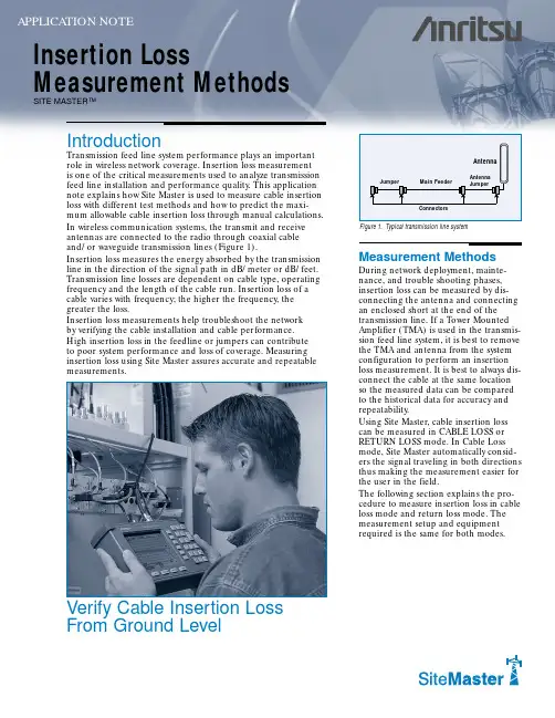
Measurement MethodsDuring network deployment, mainte-nance, and trouble shooting phases,insertion loss can be measured by dis-connecting the antenna and connecting an enclosed short at the end of the transmission line. If a Tower Mounted Amplifier (TMA) is used in the transmis-sion feed line system, it is best to remove the TMA and antenna from the system configuration to perform an insertion loss measurement. It is best to always dis-connect the cable at the same location so the measured data can be compared to the historical data for accuracy and repeatability.Using Site Master, cable insertion loss can be measured in CABLE LOSS or RETURN LOSS mode. In Cable Loss mode, Site Master automatically consid-ers the signal traveling in both directions thus making the measurement easier for the user in the field.The following section explains the pro-cedure to measure insertion loss in cable loss mode and return loss mode. The measurement setup and equipment required is the same for both modes.Insertion LossMeasurement MethodsAPPLICATION NOTEIntroductionand/or waveguide transmission lines (Figure 1).Insertion loss measures the energy absorbed by the transmission line in the direction of the signal path in dB/meter or dB/feet.Transmission line losses are dependent on cable type, operating frequency and the length of the cable run. Insertion loss of a cable varies with frequency; the higher the frequency, the greater the loss.Insertion loss measurements help troubleshoot the network by verifying the cable installation and cable performance.High insertion loss in the feedline or jumpers can contribute to poor system performance and loss of coverage. Measuring insertion loss using Site Master assures accurate and repeatable measurements.SITE MASTER™Verify Cable Insertion Loss From Ground LevelMeasuring Insertion Loss Using CABLE LOSS MODEApplication NoteRequired Equipment• Site Master Model S11xx,S33xx, or S251x • Precision Open/Short,Anritsu 22N50 or PrecisionOpen/Short/Load, Anritsu OSLN50LF• Precision Load, Anritsu SM/PL• Test Port Extension Cable,Anritsu 15NNF50-1.5C • Optional 510-90 Adapter,DC to 7.5GHz, 50 Ω,7/16(f)-N(m)Figure 3.Insertion loss measurement setup when TMA is in line.Step 4.Connect the phase stable testport extension cable to the RF port.Step 5.Calibrate the Site Master at theend of the phase stable test port extension cable. (See the section entitled “Calibrating Site Master with the Phase Stable Test Port Extension Cable” for details.)Step 6.Disconnect the antenna andconnect an enclosed precision "short" at the end of the transmission line.Step 7.Connect the other end of thetransmission line to the phase stable cable of the Site Master.A trace will be displayed on the screen when the Site Master is in continuous sweep mode.Step 8.Press the AMPLITUDE key andset the TOP and BOTTOM values of the display. In Figure 4, the TOP is set to 2 dB, and the BOTTOM is set to 5 dB.Step 9.Press the MARKER key.Step 10.Set M1to MARKER TO PEAK .Step 11.Set M2to MARKER TO VALLEY .Step 12.Calculate the insertion loss byaveraging M1 (MARKER TO PEAK) and M2 (MARKER TO VALLEY) values as follows:Step 13. Press SAVE DISPLAY and namethe trace using the soft keys and press ENTER .Saving the display is recommended for historical documentation.Saved traces can be used in the future to compare, check or verify changes in the trans-mission feedline performance.ProcedureStep 1.Power On the Site Master andpress the MODE key.Step 2.Select FREQ-CABLE LOSS usingthe Up/Down arrow key and press ENTER .Step 3.Set the start and stop frequen-cies F1and F2. As an example,F1=750 MHz and F2=850 MHz for a typical cellular frequency band.Insertion Loss Measurement SetupThe insertion loss measurement set up for a typical transmission feed line system is shown in Figure 2. Remove the antenna and connect an enclosed precision “short” at the end of the transmission line.If a Tower Mounted Amplifier (TMA)is in the transmission feed line system,remove the TMA and antenna and connect an enclosed short at the end of the transmission line. Insertion loss measurement for a transmission feed line system with a tower mounted amplifier is shown in Figure 3.Figure 2.An insertion loss measurement setup after antenna is removed.In Cable Loss mode, the Site Master automatically considers the signal path in both directions when calculating the cable insertion loss. As such, Cable Loss mode is recommended when making cable insertion loss measurements. Step 7.Connect the other end of the transmission line to the phase stable cable of the SiteMaster. A trace will be displayed on thescreen when the Site Master is in continuoussweep mode.Step 8.Press the AMPLITUDE key and set the TOP and BOTTOM values of the display. InFigure 5, the TOP is set to 4 dB, and theBOTTOM is set to 10 dB.Step 9.Press the MARKER key.Step 10.Set M1to MARKER TO PEAK.Step 11.Set M2to MARKER TO VALLEY.Step 12.Calculate the insertion loss by averaging M1 (MARKER TO PEAK) and M2 (MARKERTO VALLEY) values and dividing by two asfollows:Step 13.Press SAVE DISPLAY and name the trace using the soft keys and press ENTER. Calibrating Site Master withthe Phase Stable Test Port Extension CableThe phase stable test port extension cable is used as an extension cable to the test port of the Site Master, and ensures accurate and repeatable measurements. The phase stable cable can be moved and bent while making a measurement without causing errors in the measurement. When poor quality cables are usedas an extension test port cable, large error will be introduced in the measurements when the cableis moved.For accurate results, Site Master should be calibrated at the ambient temperature before making any measurements. The Site Master must be re-calibrated whenever the setup frequency changes, the tempera-ture exceeds the calibration temperature windowor when the test port extension cable is removedor replaced.Connect the phase stable test port extension cable to the Site Master RF Port. The Site Master with phase stable cable combination can be calibrated manually using Open, Short and Load (OSL) precision components (Figure 6), or by using the InstaCal®module. Manual calibration is explained here. For the InstaCal procedure, refer to the Site Master user guide.Note:The InstaCal module is not compatible with theSite Master S251C Model.Figure 4.Typical Insertion Loss Display in Cable Loss Mode.Measuring Insertion Lossusing RETURN LOSS MODEStep 1.Power on the Site Master and press theMODE key.Step 2.Select the FREQ-RETURN LOSS using the Up/Down arrow key and press ENTER. Step 3.Set the start and stop frequencies F1and F2.As an example, F1=750 MHz and F2=850MHz for a typical cellular frequency band. Step 4.Connect the phase stable test port extension cable to the RF port.Step 5.Calibrate the Site Master at the end ofthe phase stable test port extension cable.(See the section entitled “Calibrating SiteMaster with the Phase Stable Test PortExtension Cable” for details.)Step 6.Disconnect the antenna and connect an enclosed precision "short" at the end ofthe transmission line.Figure.Calibrating at the end of the Phase Stable Test Port Extension Cable.SALES CENTERS:United States (800) ANRITSU Europe 44 (0) 1582-433433Microwave Measurements DivisionCanada (800) ANRITSUJapan 81 (03) 3446-1111490 Jarvis Drive, Morgan Hill, CA 95037-2809South America 55 (21) 286-9141Asia-Pacific 65-2822400For example:Manual Calibration ProcedureStep 1.Power on the Site Master.Step 2.Select the appropriate frequency range.Step 3.Connect the phase stable test port extension cable tothe RF port.Step 4.Press the START CAL key. The message "Connect Open toRF OUT port or connect InstaCal module and press ENTER "will appear in the display.Step 5.Connect the OPEN precision calibration componentto the end of the test port extension cable. Press the ENTER Key.Step 6.The message "Measuring OPEN" will appear, and after themeasurement "Connect SHORT to RF OUT" will appear.Step 7.Remove the “open” and connect the “short” precision cali-bration component to the test port extension cable.Press the ENTER key.Step 8.The message "Measuring SHORT" will appear, and after themeasurement "Connect TERMINATION to RF OUT" will appear.Step 9.Remove the “short” and connect the “precision termination”at the end of the test port extension cable. Press the ENTER key.Step 10.The message "Measuring TERMINATION" will appear. Afterthe measurement, the “CAL OFF” message will change to "CAL ON" on the upper left-hand corner of the display.Step 11.Remove the precision termination from the text portextension cable.Calculating Transmission Line Insertion LossCables have different insertion losses at different frequencies.For example LDF4-40A attenuation at 1GHz is 0.022dB/ft (0.073dB/m) and at 2 GHz it is 0.0325 dB/ft (0.107 dB/m).As the frequency increases or the length of the cable run increases,the amount of cable insertion loss increases.To verify cable insertion loss measurements are reasonable, the expected insertion loss can be calculated manually using thefollowing procedure:•Calculate the estimated worst loss of each component in the transmission line system.•Add all the component’s estimated worst losses together to calculate total insertion loss in the transmission line system.Insertion loss of the =Bottom Jumper Loss transmission system + Main Cable Loss+ Top Jumper Loss + Connector Losses= 0.408 + 2.3 +0.204 +1.12= 4.03 dBCompare the measured insertion loss tothe calculated insertion loss to verify transmission line performance. The measured cable insertion loss should be lower than the calculated cable inser-tion loss.SummaryThe preferred method to measure Cable Insertion Loss using Site Master is Cable Loss mode. Cable loss mode automatically considers the signal traveling in both directions and thus makes it easier to measure the cable insertion loss in the field. Measured Insertion Loss should always be com-pared to the calculated loss to verify accuracy thus assuring transmission line performance. The calculated insertion loss is usually a “worst case scenario”.Cable insertion loss may be difficult to measure on excessivly long or highly lossy cables. When the cable insertion loss is greater than 20 dB, it will be hard to measure.All trademarks used are the property of their respective owners.Note:For Cable Loss-One Port measurements, Site Master S251C requires only one port calibration.Note:If the phase stable cable is removed from the test port, the calibration is not valid.。
学术英语写作_山东大学中国大学mooc课后章节答案期末考试题库2023年1.Bond, T., & Fox, C. M. (2015).Applying the Rasch model: Fundamentalmeasurement in the human sciences. New York, NY: Routledge. 可以判断这个reference是一篇期刊文章。
参考答案:错误2.Brown, J. D., & Bailey, K. M. (2008). Language testing courses: What are theyin 2007? Language Testing, 25, 349–384.可以判断这个reference是一篇期刊文章。
参考答案:正确3.Wikipedia information is not always reliable, so we cannot use wikipedia forresearch.参考答案:错误4.When doing research, we must only use current resources, not old ones.参考答案:错误5.Ding, W., & Lehrer, S. F. (2007). Do peers affect student achievement inChina's secondary schools?The Review of Economics and Statistics,89(2),300-312.Davies, A. (2008). Textbook trends in teaching languagenguage Testing,25(3), 327–347.Crusan, D., Plakans, L., & Gebril, A.(2016). Writing assessment literacy: Surveying second language teachers’knowledge, beliefs, and practices.Assessing Writing,28, 43-56.根据APA格式要求,该排序方式是正确的。

数据仓库专业术语表AAccess PathThe path chosen by a database management system to retrieve the requested data.Access ProviderA company which provides its customers a service whereby they can access theInternet.The user normally connects to the access provid er’s computer viaa modem using a dial up connection.Active AttackA persistent security assault by someone trying to gain restricted accessby altering data.There are multiple techniques,decryption for example,which can be used to lead the attack.Active Server Pages (ASP)Active server pages are a set of software components that run on a Web server and allow Web developers to build dynamic Web pages.Activity-Based Costing (ABC)Activity-based costing (ABC) is an information system that maintains and processes data on a firm's activities and products.It identifies the activities performed,traces cost to these activities,and then uses various cost drivers to trace the cost of activities to products.Activity-Based Management (ABM)Activity-based management(ABM) is the use of the activity-based costing tool by process owners to control and improve their operations.Because process analysis is conducted in the building of an activity-based cost model,management knows its business much better and can consequently evaluate value-added and non-value-added activities.Because a certain volume of work produces a certain outcome,"What if"analysis can be conducted to determine what resources are required of operations are scaled back or expanded.Ad ClicksAlso called clickthroughs.The number of times a user "clicks" on an online ad,often measured as a function of time("ad clicks per day").Ad Hoc QueryAny query that cannot be determined prior to the moment the query is issued.A query that consists of dynamically constructed SQL,which is usuallyconstructed by desktop-resident query tools.Ad Hoc Query ToolAn end-user tool that accepts an English-like or point-and-click request for data and constructs an ad-hoc query to retrieve the desired result.Administrative DataIn a data warehouse,the data that helps a warehouse administrator manage the warehouse.Examples of administrative data are user profiles and order history data.Aggregate DataData that is the result of applying a process to combine data elements.Data that is taken collectively or in summary form.AggregatorThis is an e-commerce business model in which the Web site sells products or services which it does not produce or warehouse.An aggregator creates an environment where multiple providers (sellers) must compete on terms determined by the use.AlertsA notification from an event that has exceeded a pre-defined threshold.AnalystSomeone who creates views for analytic interpretation of data,performs calculations and distributes the resulting information in the form of reports.Analytic ApplicationsPackaged software that meets three distinct conditions:process support,separation of function and time-oriented,integrated data.Analytic applications expand the reach of business intelligence to an extended user base,packaging these technologies in a business context.AnalyticsThe process and techniques for the exploration and analysis of business data to discover and identify new and meaningful information and trends that allow for analysis to take place.AppletA small Java program that can be embedded in an HTML page.They cannot accesscertain resources on local computers such as files and serial devices and are prohibited from communication with most other computers across a network.Application Service Provider (ASP)ASPs provide the infrastructure needed to deliver reliable application access,including enterprise applications,hardware platforms,operating systems,database systems,network hardware as well as the technical expertise to make it all work for a monthly service charge.ASCIIAmerican Standard Code for Information Interchange.An eight-bit code for character representation,includes seven bits plus parity.ASPApplication Service Provider.A company that offers access over the Internet to application programs and related services that would otherwise have to be located in other own personal or enterprise computers.Atomic DataData elements that represent the lowest level of detail.For example,in a daily sales report,the individual items sold would be atomic data,while rollups such as invoice and summary totals from invoices are aggregate data.AttributeA field represented by a column within an object (entity).An object may bea table,view or report.An attribute is also associated with an SGML(HTML)tag used to further define the usage.Authorization RequestA request initiated by a consumer to access data for which the consumer doesnot presently have access privileges.Authorization RulesCriteria used to determine whether or not an individual,group,or application may access reference data or a process.AvailabilityUser access to applications and/or data stores that reside and execute on computing systems accessing information that resides in files and databases suppo rted by an organization’s various operating environments.BB2BBusiness-to-business commerce conducted over the Web.B2CBusiness-to-consumer commerce conducted over the Internet.It links consumers to commercial entities in one-way networks.Balanced ScorecardA comprehensive,top-down view of organizational performance with a strongfocus on vision and strategy.In 1992 the founding fathers of the Balanced Scorecard,Drs.Robert Kaplan and David Norton,debuted their methodology in the Harvard Business Review.Then,in 1996,they released The BalancedScorecard Translating Strategy into Action,the so-called bible of the Balanced Scorecard.Balanced Scorecard CollaborativeA professional services firm dedicated to the worldwideawareness,use,enhancement and integrity of the balanced scorecard as a value-added management process.Balanced Scorecard Collaborative CertificationAn industry-standard certification offered to software providers whose balanced scorecard applications meet the functional standards of Kaplan and Norton.These are applications that will enable end users to achieve the benefits of the balanced scorecard management process.Baldrige Criteria for Performance ExcellenceCriteria providing a systems perspective for understanding performance management.They reflect validated, leading management practices against which an organization can measure itself.With their acceptance nationally and internationally as the model for performance excellence,the criteria represent a common language for communication among organizations for sharing best practices.BannerA picture or graphic that stretches horizontally across a Web page.These canbe used to title the Web page,start or separate different sections,create links to other Web pages,or provide a place for advertisements.Banner AdvertisingA marketing mechanism that contains strips of advertisements that aresporadically positioned on a web page and are extremely popular on the World Wide Web.These types of ads generally take up a considerable amount of bandwidth and are sometimes disturbing to the Web user.Base TablesThe normalized data structures maintained in the target warehousing database.Also known as the detail data.Basel II New Accord (Basel 2,New Accord)This is a set of banking standards,which will regulate finance and banking for countries in the European Union.The Basel Committee on Banking Supervision is tasked with the goal to complete the New Accord by mid-year 2004,with implementation to take effect in member countries by year-end 2006.To that end,work already has begun in a number of countries on draft rules that would integrate Basel capital standards with national capital regimes.Basel II is focused specifically on global banks and financial institutions and ensures liquidity of those institutions for the protection of public trust.BenchmarkingA point of reference for measurement.Benefit SegmentationThe process of grouping customers into market segments according to the benefits they seek from the product.Refers to their needs and wants only.Best PracticesA case study considered to be a good example of a business discipline.Bidirectional ExtractsThe ability to extract,cleanse and transfer data in two directions among different types of databases,including hierarchical,networked and relational databases.Braking MechanismA software mechanism that prevents users from querying the operationaldatabase once transaction loads reach a certain level.Bricks and MortarRefers to businesses that exist in the real world as opposed to just the cyber world such as bricks-and-mortar retail outlets,bricks-and-mortar warehouses,etc.BrowserThe generic term for software programs that retrieve,display and print information World Wide Web.The most popular browsers are Microsoft Internet Explorer,Netscape Navigator and Mosaic.Mosaic was the first browser to introduce graphics.Previously,users were only allowed to view the text of Web pages.Currently,Microsoft Outlook is the most popular browser in the world.Bulk Data TransferA software-based mechanism designed to move large data files.It supportscompression,blocking and buffering to optimize transfer times.Business Activity Monitoring (BAM)BAM is a business solution that is supported by an advanced technical infrastructure that enables rapid insight into new business strategies,the reduction of operating cost by real-time identification of issues and improved process performance.Business ArchitectureOne of the four layers of an information systems architecture.A business architecture describes the functions a business performs and the information it uses.Business ContinuityThe degree to which an organization may achieve uninterrupted stability of systems and operational procedures.Business DataInformation about people,places,things,business rules,and events,which is used to operate the business.It is not metadata.(Metadata defines and describes business data.)Business DriversThe people,information,and tasks that support the fulfillment of a business objective.Business Intelligence (BI)Business intelligence is actually an environment in which business users receive data that is reliable,consistent,understandable,easily manipulated and timely.With this data,business users are able to conduct analyses thatyield overall understanding of where the business has been,where it is now and where it will be in the near future.Business intelligence serves two main purposes.It monitors the financial and operational health of the organization(reports,alerts,alarms,analysis tools,key performance indicators and dashboards).It also regulates the operation of the organization providing two-way integration with operational systems and information feedback analysis.Business Intelligence PlatformA foundation of enabling tools and technologies necessary for the developmentand deployment of business intelligence and business performance management applications.Business Intelligence Service Provider (BISP)A natural extension of the ASP,application of data warehousing and businessintelligence (BI) methodologies and technologies to the ASP model.BISPs tie into information systems behind a corporation's firewall,providing traditional data warehouse and analytic application capabilities for Internet-based e-businesses,especially e-commerce Web sites and are hosted off site.Business Intelligence SoftwareA category of software that enables companies to access,analyze and shareinformation to understand how the business is performing and to improve decision making.Business Intelligence ToolsThe tools and technologies used to access and analyze business information.They include online analytical processing(OLAP) technologies,data miningand advanced analytics;end-user tools for ad hoc query and analysis,enterprise class query,analysis and reporting including dashboards for performance monitoring;and production reporting against all enterprise data sources.Business ModelA view of the business at any given point in time.The view can be from aprocess,data,event or resource perspective,and can be the past,present or future state of the business.Business Performance Calibration (BPC)The continuous,near real-time forecasting and analysis of related performance metrics to achieve balanced performance,i.e.,efficient growth and the optimal management of resources.Business Performance Intelligence (BPI)A subset of the BI market and involves planning and budgeting,BalancedScorecard performance management and activity-based costing.Business Performance Management (BPM)Applications that help direct modeling or scenario exploration activities.Rather than simply exploring what happened and why,the application can help the user consider the implications of alternative courses of action before they become operational.Performance management suggests an explicit relationship to action,and modeling is the key link to do this.Business Performance MeasurementApplications that provide support for specific KPIs(key performance indicators) enable a business to measure their performance.This is often coupled with comparative information from industry sources,so a company can compare their performance against that of others in their industry.Business performance measurement applications support the analysis phase of the business improvement cycle.Business TransactionA unit of work acted upon by a data capture system to create,modify,or deletebusiness data.Each transaction represents a single valued fact describinga single business event.CC-Commerce (Collaborative-Commerce)A business strategy that motivates value-chain partners with a commonbusiness interest to generate value through sharing information at all phases of the business cycle (from product development to distribution).C2BThe financial interaction,initiated by a consumer,between a consumer and business.CachePronounced "cash". The storage of recently visited sites and data which can be accessed from computer memory instead of linking the server each time you return to the site.This speeds the access time, but does not reflect any changes to the site while in the cache.On rapidly changing sites you may needto click the reload button in order to read the most recent changes.Call CenterThe part of an organization that handles inbound/outbound communications with customers.Campaign ManagementDetailed tracking, reporting and analysis that provides precise measurements regarding current marketing campaigns,how they are performing and the types of leads they attract.Cartesian productA Cartesian join will get you a Cartesian product.A Cartesian join is whenyou join every row of one table to every row of another table.You can also get one by joining every row of a table to every row of itself.Cascading Style Sheet (CSS)Cascading style sheets is a style sheet language that enables authors and users to attach style(fonts,spacing and aural cues) to structure that include HTML and XML applications.CASEComputer Aided Software Engineering.CASE ManagementThe management of information between multiple CASE encyclopedias," whether the same or different CASE tools.CatalogA component of a data dictionary that contains a directory of its DBMS objectsas well as attributes of each object.CellData point defined by one member of each dimension of a multidimensional structure.Often,potential cells in multidimensional structures are empty,leading to "sparse" storage.Central WarehouseA database created from operational extracts that adheres to asingle,consistent,enterprise data model to ensure consistency of decision-support data across the corporation.A style of computing where all the information systems are located and managed from a single physical location.Change Data CaptureThe process of capturing changes made to a production data source.Change data capture is typically performed by reading the source DBMS log.It consolidates units of work,ensures data is synchronized with the original source,and reduces data volume in a data warehousing environment.ChurnDescribes customer attrition.A high churn rate implies high customer disloyalty.Classic Data Warehouse DevelopmentThe process of building an enterprise business model,creating a system datamodel,defining and designing a data warehouse architecture,constructing the physical database,and lastly populating the warehouses database.Clicks and MortarA business that has successfully integrated its online existence with itsoffline,real-world existence.For example,a retail store that allows customers to order products online or purchase products at its store location.ClickthroughThe percentage of advertisements or other content a user clicks on or chooses to view.ClientA software program used to contact and obtain data from a server softwareprogram on another computer.Each client program is designed to work with one or more specific kinds of server programs, and each server requires a specific kid of client.Client/ServerA distributed technology approach where the processing is divided by function.The server performs shared functions——managing communications,providing database services,etc.The client performs individual user functions——providing customized interfaces,performing screen to screen navigation,offering help functions,etc.Client/Server ArchitectureA networked environment where a smaller system such as a PC interacts witha larger,faster system.This allows the processing to be performed on thelarger system which frees the user's PC.The larger system is able to connect and disconnect from the clients in order to more efficiently process the data.Client/Server ProcessingA form of cooperative processing in which the end-user interaction is througha programmable workstation (desktop) that must execute some part of theapplication logic over and above display formatting and terminal emulation.CollectionA set of data that resulted from a DBMS query.COM+Provides an enterprise development environment,based on the Microsoft component object model (COM),for creating component-based,distributed applications.Common Object Model (COM)Common object model is an object-based programming specification,designed to provide object interoperability through sets of predefined routines called interfaces.Common Object Request Broker Architecture (CORBA)Common object request broker architecture is the Object Management Group(OMG) vendor-independent architecture and infrastructure,which computer applications use to work together over networks.Communications IntegrityAn operational quality that ensures transmitted data has been accurately received at its destination.ConsolidationThe process that takes data from different systems and entities,and possibly desperate formats,and combines and aggregates that information to create a unified view.ConsumerAn individual,group or application that accesses data/information in a data warehouse.Consumer ProfileIdentification of an individual,group or application and a profile of the data they request and use:the kinds of warehouse data, physical relational tables needed,and the required location and frequency of the data (when,where,and in what form it is to be delivered).Content ManagementThe processes and workflows involved in organizing,categorizing,and structuring information resources so that they can be stored,published,and reused in multiple ways.A content management system(CMS) is used to collect,manage and publish content,storing the content either as components or whole documents,while maintaining the links between components.It may also provides for content revision control.Continuous AvailabilityA protocol,associated execution and ready state of functionality thatvirtually guarantees computing-system operational continuity in any downtime event.Continuous availability concerns itself with 1) the recovery of applications,data and data transactions committed up to the moment of system loss;and 2) seamless,24x7 system availability that offsets any planned or unplanned downtime event.Control DataData that guides a process. For example,indicators,flags,counters and parameters.CookiesCookies are text files that are stored at the client's hard drive.When a browser requests a document,the web server creates a fragment of data,which is sent to the browser and stored at the client's computer.Afterward,when the browser solicits another document,the cookie is sent with the request.Cookies are very similar to the caller id boxes that have become so popular in that they provide telemarketers with such relevant information as:the consumers name,address,and previous purchase payment record.Cooperative ProcessingA style of computer application processing in which thepresentation,business logic,and data management are split among two or more software services that operate on one or more computers.In cooperative processing,individual software programs (services) perform specific functions that are invoked by means of parameterized messages exchanged between them.Copy ManagementThe analysis of the business benefit realized by the cost of expenditure on some resource,tool,or application development.Corporate Performance ManagementAn umbrella term used to describe the methodologies, metrics,processes and systems used to monitor and manage the business performance of an enterprise.Cost Benefit AnalysisThe analysis of the business benefit realized by the cost of expenditure on some resource,tool,or application development.Critical Success FactorsKey areas of activity in which favorable results are necessary for a company to reach its goal.CRMCustomer Relationship Management.CrosstabA process or function that combines and/or summarizes data from one or moresources into a concise format for analysis or reporting.CubeA data cube is a multidimensional structure that contains an aggregate valueat each point,i.e.,the result of applying an aggregate function to an underlying relation.Data cubes are used to implement online analytical processing (OLAP).Currency DateThe date the data is considered effective.It is also known as the "as of"date or temporal currency.Customer Relationship ManagementThe idea of establishing relationships with customers on an individual basis,then using that information to treat different customers differently.Customer buying profiles and churn analysis are examples of decision support activities that can affect the success of customer relationships.Cyber marketingThis term refers to any type of Internet-based promotion.This includes Web sites, targeted e-mail,Internet bulletin boards, sites where customers can dial-in and download files,and sites that engage in internet commerce by offering products for sell over the Internet.The term doesn't have a strict meaning,though,and many marketing managers use it to cover any computer-based marketing tools.DDashboardAn application or custom user interface that organizes and presents information in a way that is easy to read.The information may be integrated from multiple components into a unified display.A dashboard helps monitor individual,business unit and organizational performance and processes fora greater understanding of the business.DataItems representing facts,text,graphics,bit-mapped images,sound,analog or digital live-video segments.Data is the raw material of a system supplied by data producers and is used by information consumers to create information.Data Access ToolsAn end-user oriented tool that allows users to build SQL queries by pointing and clicking on a list of tables and fields in the data warehouse.Data AcquisitionIdentification,selection and mapping of source data to target data.Detection of source data changes,data extraction techniques,timing of data extracts,data transformation techniques,frequency of database loads and levels of data summary are among the difficult data acquisition challenges.Data Analysis and Presentation ToolsSoftware that provides a logical view of data in a warehouse.Some create simple aliases for table and column names;others create data that identify the contents and location of data in the warehouse.Data ApplianceA combination of hardware,software,DBMSs and storage,all under oneumbrella.A black box that yields high performance in both speed and storage, making the BI environment simpler and more useful to the users.Data ConsumerAn individual,group,or application that receives data in the form of a collection.The data is used for query,analysis,and reporting.Data CustodianThe individual assigned the responsibility of operating systems, data centers, data warehouses, operational databases, and business operations in conformance with the policies and practices prescribed by the data owner.Data DictionaryA database about data and database structures. A catalog of all data elements,containing their names, structures, and information about their usage. A central location for metadata. Normally, data dictionaries are designed to store a limited set of available metadata, concentrating on the information relating to the data elements, databases, files and programs of implemented systems.Data DirectoryA collection of definitions, rules and advisories of data, designed to beused as a guide or reference with the data warehouse. The directory includes definitions, examples, relations, functions and equivalents in other environments.Data ElementThe most elementary unit of data that can be identified and described in a dictionary or repository which cannot be subdivided.Data Extraction SoftwareSoftware that reads one or more sources of data and creates a new image of the data.Data Flow DiagramA diagram that shows the normal flow of data between services as well as theflow of data between data stores and services.Data IntegrationPulling together and reconciling dispersed data for analytic purposes that organizations have maintained in multiple, heterogeneous systems. Data needs to be accessed and extracted, moved and loaded, validated and cleaned, and standardized and transformed.Data LoadingThe process of populating the data warehouse. Data loading is provided by DBMS-specific load processes, DBMS insert processes, and independent fastload processes.Data ManagementControlling, protecting, and facilitating access to data in order to provide information consumers with timely access to the data they need. The functions provided by a database management system.Data Management SoftwareSoftware that converts data into a unified format by taking derived data to create new fields, merging files, summarizing and filtering data; the process of reading data from operational systems. Data Management Software is also known as data extraction software.Data MappingThe process of assigning a source data element to a target data element.。
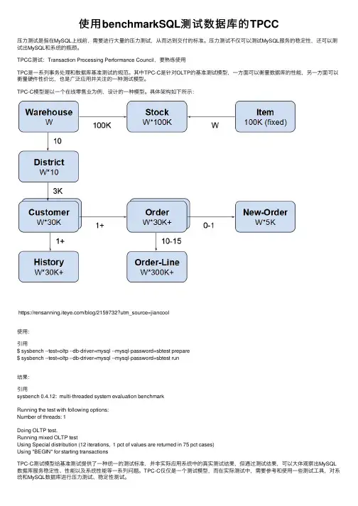
使⽤benchmarkSQL测试数据库的TPCC压⼒测试是指在MySQL上线前,需要进⾏⼤量的压⼒测试,从⽽达到交付的标准。
压⼒测试不仅可以测试MySQL服务的稳定性,还可以测试出MySQL和系统的瓶颈。
TPCC测试:Transaction Processing Performance Council,要熟练使⽤TPC是⼀系列事务处理和数据库基准测试的规范。
其中TPC-C是针对OLTP的基准测试模型,⼀⽅⾯可以衡量数据库的性能,另⼀⽅⾯可以衡量硬件性价⽐,也是⼴泛应⽤并关注的⼀种测试模型。
TPC-C模型是以⼀个在线零售业为例,设计的⼀种模型。
具体架构如下所⽰:https:///blog/2159732?utm_source=jiancool使⽤:引⽤$ sysbench --test=oltp --db-driver=mysql --mysql-password=sbtest prepare$ sysbench --test=oltp --db-driver=mysql --mysql-password=sbtest run结果:引⽤sysbench 0.4.12: multi-threaded system evaluation benchmarkRunning the test with following options:Number of threads: 1Doing OLTP test.Running mixed OLTP testUsing Special distribution (12 iterations, 1 pct of values are returned in 75 pct cases)Using "BEGIN" for starting transactionsTPC-C测试模型给基准测试提供了⼀种统⼀的测试标准,并⾮实际应⽤系统中的真实测试结果,但通过测试结果,可以⼤体观察出MySQL 数据库服务稳定性、性能以及系统性能等⼀系列问题。
一种无人机群协同无源定位资源优化调度方法蔡㊀伟,张晓峰(中国电子科技集团公司第五十一研究所,上海201802)摘要:无人机群是执行电子侦察的有效载体,以无人机群侦察结果作为对固定或缓动辐射源的定位参数,在电子对抗作战体系中有重要意义.由于无人机平台负荷限制,其电子侦察的瞬时空G频域覆盖和测量精度受限.提出了一种对观察窗口侦察资源的协同优化调度方法,优化当前场面下各机电子侦察的瞬时空G频域覆盖选择,提高无源定位中每个定位参数对定位结果的效用,降低获取定位参数所需要的对侦察资源的占用,从而提升无人机群可同时应对的目标数.仿真结果表明,该方法可有效地降低同一目标的重访频次需求,这能显著提高可同时处理的目标数,并在较差的测向指标下仍能达到有意义的定位性能.关键词:无源电子侦察;无人机群;观察窗口;无源定位中图分类号:T N 971 1㊀㊀㊀㊀㊀㊀㊀文献标识码:A㊀㊀㊀㊀㊀㊀㊀文章编号:C N 32G1413(2018)03G0054G05D O I :10.16426/j .c n k i .jc d z d k .2018.03.013AR e s o u r c eO p t i m i z a t i o nS c h e d u l i n g Me t h o df o r C o o pe r a t i v eP a s s i v eL o c a t i o no fU A V s C A IW e i ,Z H A N G X i a o Gf e n g(51s tR e s e a r c h I n s t i t u t e o fC E T C ,S h a n gh a i 201802,C h i n a )A b s t r a c t :U n m a n n e d a e r i a l v e h i c l e s (U A V s )a r e e f f e c t i v e c a r r i e r s f o r e l e c t r o n i c r e c o n n a i s s a n c e .I t i so f g r e a t s i g n i f i c a n c e t ou s e t h e r e c o n n a i s s a n c e r e s u l t so fU A V sa s t h e p o s i t i o n i n gpa r a m e t e r s f o r f i x e do r s l o w m o v i n g e m i t t e r i n t h e e l e c t r o n i cw a r f a r e c o mb a t s y s t e m.D u e t o t h e l o a d l i m i t a t i o no f U A V p l a t f o r m ,t h e i n s t a n t a n e o u s s p ac e Gf r e q u e n c y c o v e r a g e a n dm e a s u r e m e n t a c c u r a c y o f e l e c t r o n i c r e c o n n a i s s a n c e a r e l i m i t ed .T h i s p a pe r p r o p o s e s a c o o p e r a t i v e o p t i m i z a t i o n s c h e d u l i n g m e t h o d of r e Gc o n n a i s s a n c e r e s o u r c e s f o r o b s e r v a t i o nw i n d o w ,o p t i m i z e s t h e i n s t a n t a n e o u s s p a c e Gf r e q u e n c y c o v e r Gag e s e l e c t i o n o f e l e c t r o n i c r e c o n n a i s s a n c e f o r e a c hU A V i n th e p r e s e n t s c e n e ,i m p r o v e s t h e u t i l i t y of e a c h l o c a t i o n p a r a m e t e r o n t h e p a s s i v e l o c a t i o n r e s u l t ,r e d u c e s t h e o c c u p a n c y of r e c o n n a i s s a n c e r e Gs o u r c e sn e e d e d f o r o b t a i n i ng th e l o c a ti o n p a r a m e t e r s ,t h u s p r o m o t e s t h e n u m b e r o f t a r g e t s t h a t t h e U A V s c a nd e a lw i t h a t t h e s a m e t i m e .T h e s i m u l a t i o n r e s u l t s s h o wt h a t t h i sm e t h o d c a n e f f e c t i v e l yr e d u c et h er e v i s i tf r e q u e n c y d e m a n d o ft h es a m et a r g e t ,w h i c h c a n s i g n i f i c a n t l y pr o m o t et h e n u m b e r o f t a r g e t s t h a t c a nb e p r o c e s s e d a t t h e s a m e t i m e ,a n d c a n s t i l l a c h i e v em e a n i n g f u l po s i t i o Gn i n gp e r f o r m a n c eu n d e r t h e p o o r d i r e c t i o n f i n d i n gi n d e x .K e y wo r d s :p a s s i v e e l e c t r o n i c r e c o n n a i s s a n c e ;u n m a n n e d a e r i a l v e h i c l e s ;o b s e r v a t i o n w i n d o w ;pa s s i v e l o c a t i o n 收稿日期:201804090㊀引㊀言无人机群是近年来高速发展的一种载具平台,可以定制携带多种设备,遂行多样化的任务.在电子对抗领域,无人机群是执行电子侦察的有效载体,使用无人机群搭载无源侦察设备,可以实现快速动态部署,用于前出侦察㊁重点侦察和补盲侦察.无源电磁侦察设备在每个工作节拍中,选择适2018年6月舰船电子对抗J u n .2018第41卷第3期S H I P B O A R DE L E C T R O N I CC O U N T E R M E A S U R EV o l .41N o .3当的空间范围和频谱范围,接收㊁检测㊁分辨该范围内出现的电磁信号,并测量信号的参数.其中一些电磁参数是与辐射源的空间行为有关系的,特别是信号的到达方位参数.以无人机群侦察结果,作为对固定或缓动辐射源的定位参数,可以低成本地实现对目标的多角度观测,增加定位参考信息,在电子对抗作战体系中有重要意义.然而,与地基㊁船载㊁大型机载设备相比,由于无人机平台负荷限制,通常无人机载无源侦察设备的天线㊁接收机和处理器规模受到制约,导致其电子侦察的瞬时空G频域覆盖能力较弱;并且受限于可搭载的测量体制,导致参数测量精度较差.例如在测向能力上,大型设备可以采用长基线干涉仪㊁数字波束合成等技术,将测量误差均方根控制到0 1ʎ数量级;而无人机载设备,特别是小型无人机的载荷设备,测量误差均方根在较恶劣条件下可能达到10ʎ或更高.在参数测量能力本身受到限制的情况下,为了提升系统总体效能,需要研究无人机群协同工作方法,例如协同定位.但现有的对无人机群协同定位的研究工作,在无源侦察设备的情形中应用存在问题.一部分工作的定位目标是无人机群自身,用于解决导航引导不足的问题[1G2];而定位目标是无人机群的侦察或攻击目标的研究工作中,优化的资源通常都是无人机航迹[3G4].然而,在无人机群的实际应用中,电子侦察子系统对航迹的决定权往往低于主动雷达子系统和火力子系统,因此无法按电子侦察子系统的要求申请到最优航迹,只能获取到后续航迹设定.针对上述情况,必须从侦察控制着手,研究一定航迹下的优化措施.本文提出了一种无人机群协同无源定位系统的设计,优化当前场面下各机电子侦察的瞬时空G频域覆盖选择,在定位性能达到要求的前提下,降低获取定位参数所需要的对侦察资源的占用,从而增大无人机群的侦察自由度,提升无人机群可同时应对的目标数.1㊀侦察资源优化调度控制框架执行电子侦察任务的无人机群,在通信层面上可能以自组网方式或星状拓扑相连接,而在控制逻辑层面上,通常都服从单一控制站的指控,如图1所示.其中有1个控制站和4架无人机,双虚线表示通信连接,双箭头实线表示控制逻辑连接.将当前时间记为时间零点.控制站知道每架无图1㊀典型的无人机群人机的航路规划,也就是后续各时间点t时无人机的位置s i(t)和姿态:机首方向单位矢量ψi(t)㊁右侧方向单位矢量ξi(t).无人机的侦察能力在时空频域都是受限的.在空间域,记瞬时空间覆盖的各种可选范围为D1~ D D,其中每种可选范围是相对于本机的一个方位角范围;在频谱域,记瞬时频域覆盖的各种可选范围为F1~F F.无人机的控制策略就是决定空域和频域覆盖的选择,每架无人机具有相同的侦察控制时间节拍T s.1组时空频选择称为1个观察窗口.与目标的时空频行为匹配的观察窗口里才能侦收到目标的信号.针对某个固定或缓动目标,整个系统对它的侦察过程分为扫描㊁发现和跟踪3个阶段.系统一开始工作在扫描阶段;当观察到目标的电磁信号时,进入发现阶段,此时不知道目标位置;当对目标的观测足够多,可以确定目标位置时,进入跟踪阶段.为了提高效能,需要特别关注处于发现阶段的目标.但发现阶段目标的位置不明或不够确定,因此需要无人机群配合,扩大对目标的观察窗口的覆盖范围,以尽早确认目标位置.在跟踪阶段,主要任务是确认目标异动和提高定位精度,因此可以适当减少观察窗口,选择其中效用最高的,从而减少资源占用.设计调度控制框架如图2所示.其中省略了系统默认保留的用于场面监视的扫描节拍.可以看到,发现阶段与跟踪阶段的行为模式是相似的,都需要选择能观测到目标的观察窗口.但这2个阶段的具体策略有所不同.在发现阶段,为了尽快确认目标,应该尽可能分配到这些观察窗口;而在跟踪阶段,需要考虑如何在这些观察窗口中精选,收敛性判断也与此具有相同的判据.2㊀观察窗口匹配图2所示的调度控制框架依赖于对观察窗口选55第3期蔡伟等:一种无人机群协同无源定位资源优化调度方法图2㊀调度控制框架择.下面依次从频㊁空㊁时3个方面研究匹配要求.首先是频域方面.根据无源电子侦察的特性,接收的电磁波是单程传播,而不是雷达的双程传播,因此通常只要接收天线主瓣对准目标,无论目标是以主瓣还是副瓣对准接收机,都能收到信号.所以,频域的主要选择依据是将接收机通带控制到目标发射频点.其次是空域方面.受限于测向精度,目标的推测位置可能会分布在较大的范围.因此,需要尽量让各机的空域选择覆盖可能区域.设计算法流程如图3所示.其中覆盖数是指待覆盖区中所有点最少被几个空域覆盖到.提高覆盖数有利于提高总的截获概率.再次是时域方面.如果不需要对目标的电磁特性做详细刻画,对时窗选择就没有严格的限制,因此可以根据对定位的效用来释放时窗.3㊀观察窗口效用评判在跟踪阶段以及在判断定位收敛时,需要分析定位精度情况和预计下一个观察窗口对定位的效用.这需要根据定位情况进行推算.记固定目标或缓动目标的真实位置为x,推测位置为x︿.当前时刻为0时刻,在一系列历史时间点{t n}上,观测目标的无人机编号为i n,在该时刻,此无人机位置为s n=s i n(t n),根据姿态确定了0ʎ方向单位矢量ψn=ψi n(t n)和90ʎ方向矢量ξn=图3㊀观察窗口的空域协同ξi n(t n),在该标架下目标相对无人机的方位角为θn,按推测位置的估计值则为θ︿n,则有如下定位方程:‹x-s n,-ψn s i nθn+ξn c o sθn›=0(1)㊀㊀实际测向结果θ n带测向误差δθn,假设误差的分布符合零均值联合正态分布N(0,σ2n),且不同的测向结果之间误差独立同分布.近似地有:δθnʈs i nδθn=(x-s n),-ψn s i nθn+ξn c o sθn(2)e a d ef a a -1(3)式中:表示矢量单位化.㊀㊀考虑所有δθn的联合概率分布的似然比: F=ðnσ-2n‹(x-s n),-ψn s i nθn+ξn c o sθn›2(4)㊀㊀通常测向误差δθn和位置估计误差δx不会过于巨大,近似地有:Fʈðnσ-2n‹x︿-s n(),-ψn s i nθ n+ξn c o sθ n›2(5)x︿=a r g m i nx︿F(6)㊀㊀则对定位结果应有如下矢量为0:d∂F∂x︿=dðθ︿n-θ nσ2n∂θ︿n∂x︿(7)65舰船电子对抗㊀㊀㊀第41卷㊀ð∂θ︿n ∂x ︿æèçöø÷T∂θ︿n ∂x ︿æèççöø÷÷δx =ð∂θ︿n ∂x ︿æèççöø÷÷Tθ n -θ︿n ()(8)㊀㊀得到定位误差的协方差的估计值(其中n θ︿n 表示与θ︿n 正交的法线,即(θ︿n +π/2)):v a r δx =A -1b b T A -1(9)A =ðn θ︿n n θ︿nTx ︿-s n2(10)b =ðn θ︿nx ︿-s nθ n -θ︿n()(11)㊀㊀二维情况下,可以进一步得到C E P 50椭圆的轴长平方和为2l n 2t r (v a r δx ).通过选取适当的观察窗口,使新的n θ︿n 与之前的其它n θ︿n 夹角较大,可以使t r (v a r δx )一次性有可观的下降.因此,可以定义高效观察窗口的准则:本观察窗口使t r (v a r δx )获得10%下降的概率超过50%.如果当前节拍中没有这样的观察窗,那么在跟踪阶段可以放弃本节拍的测向用定位的接收,因为这样的接收效用并不高.4㊀场景仿真为了验证本文协同优化调度方法的效能,按照作战作用方式,设计如下测试场景:我方使用3架无人机A ㊁B ㊁C ,起始位置分别位于(0k m ,0k m )㊁(30k m ,0k m )㊁(60k m ,0k m ),均以50m /s 速度沿x 轴正向移动.无人机具有4个90ʎ空域覆盖,中心方向分别为前㊁左㊁后㊁右.各机测向误差均方根为10ʎ,侦测范围300k m .为简化记,假设频域是宽开的,侦察节拍为1s ,辐射源目标位于(25k m ,200k m )处,假设无人机A 先发现目标.根据本文协同优化调度方法,进行了100次平行仿真试验.将结果分为对发现阶段的变化情况和跟踪阶段的选择情况两部分介绍.发现阶段,工作情况如下所述.起始节拍,A 发现目标.下一节拍A ㊁B ㊁C 将分别选择左㊁左㊁后空域,以保证覆盖数达到2,如图4所示.第2个节拍,B 也收到目标信号,C 收不到信号.可以确认目标位于此时的A ㊁B ㊁C 的左空域,如图5所示.虽然由于测向误差较大,定位误差范围可能很图4㊀发现阶段工作情况1图5㊀发现阶段工作情况2大,但目标的可能范围已经大致确认.此时可以转入跟踪阶段.下一节拍中,C 收到信号,由于基线A C 较长,可以在第3个节拍就获得相对可用的定位结果.如果不做B ㊁C 的协同,仅由A 观测,由于无人机位置仅移动了100m ,对200k m 外的目标完全无法形成有意义的测向交叉,无法确定目标的大致位置.然后统计了300个节拍下各次平行试验的观察窗口占用(图6)㊁定位精度收敛情况(图7).作为对比,也测试了仅使用A 单机定位的情况(图8).可以看到,一方面,本方法使得资源占用有明显降低,省出来的资源可以用来观察其他目标;另一方面,通过协作方式可以使在单机下无法定位的短时间内,形成有一定实用意义的结果(根据图7,相当于在1m i n 内达到约30%的定位精度,这是在10ʎ这种非常大的测向误差下).75第3期蔡伟等:一种无人机群协同无源定位资源优化调度方法图6㊀观察窗口占用情况图7㊀定位收敛情况5㊀结束语本文通过分析无人机群协同执行无源电子侦察任务时对观察窗口的使用效用,提出了一种对观察窗口侦察资源的协同优化调度方法.通过对观察窗图8㊀定位收敛情况与单机对比口与目标的匹配,以及观察窗口效用的评估,提高了观察窗口的利用效率.仿真结果表明,该方法可有效地降低同一目标的重访频次需求,这能显著提高可同时处理的目标数;并在较差的测向指标下仍能达到有意义的定位性能.参考文献[1]㊀万九卿,布少聪,钟丽萍.基于混合动态信念传播的多无人机协同定位算法[J ].北京航空航天大学学报,2016,42(5):934944.[2]㊀杜锋,李广侠,田世伟,等.基于数据链的协同定位综述[C ]//第十二届卫星通信学术年会.北京,2016:378384.[3]㊀胡中华.基于智能优化算法的无人机航迹规划若干关键技术研究[D ].南京:南京航空航天大学,2011.[4]㊀辛亭.多无人机协同作战关键技术研究[D ].南京:南京航空航天大学,2009.㊀㊀(上接第23页)[4]㊀梁晓龙,孙强,尹忠海,等.大规模无人系统集群智能控制方法综述[J ].计算机应用研究,2015,32(1):1116.[5]㊀D O R I G O M ,MA N I E Z Z O V ,C O L O R N I A.A n ts y s t e m :o p t i m i z a t i o nb y a c o l o n y o f c o o p e r a t i n g a g e n t s [J ].I E E E T r a n s a c t i o n s o n S ys t e m s M a n &C yb e r n e t ic sP a r tB ,1996,26(1):2941.[6]㊀B O N A B E A U E ,D O R I G O M ,T H E R A U L A ZG.I n s pi Gr a t i o n f o r o pt i m i z a t i o n f r o ms o c i a l i n s e c tb e h a v i o r [J ].N a t u r e ,2000,406(6791):3942.[7]㊀N A G Y M ,ÁK O SZ ,B I R O D ,e t a l .H i e r a r c h i c a l g r o u pd y n a m i c s i n p i ge o nf l o c k s [J ].N a t u r e ,2010,464(7290):890893.[8]㊀B O N A B E A U E ,D O R I G O M ,T H E R A U L A Z G.S w a r mI n t e l l i g e n c e :F r o m N a t u r a l t oA r t i f i c i a l S y s t e m s [M ].N e w Y o r k :O x f o r dU n i v e r s i t y P r e s s ,1999.[9]㊀T H E R A U L A ZG ,B O N A B E A U E ,A b r i e fh i s t o r y o f s t i g m e r g y[J ].A r t i f i c i a l L i f e ,1999,5(2):97116.[10]魏星.基于粒子群算法的飞行控制律参数设计研究[J ].西安航空学院学报,2017,35(1):37.85舰船电子对抗㊀㊀㊀第41卷㊀。

safety manualrelease09/20|revision43.002|TESSY v4.3ImprintRazorcat Development GmbHWitzlebenplatz4Germany,14057Berlintel:+49(030)5363570fax:+49(030)53635760e-mail:********************internet:Windows is a registered trademark of Microsoft.TESSY and CTE are registered trademarks of Ra-zorcat Development GmbH.All other registered or unregistered trademarks referenced herein are the property of their respectiveowners and no trademark rights to the same is claimed.Liability exclusionRazorcat Development GmbH assumes no liability for damage that is caused by improper installationor improper use of the software or the non-observance of the handling instructions described in thismanual.ThanksWe would like to thank Frank Büchner,Hitex Development Tools GmbH for his valuable contributionand commitment in supporting TESSY and spotlighting functionalities and features.2TESSY4.3Safety ManualContentsSafety Manual4 About TESSY (4)Safety Manual (5)Core workflow and registration for safety information (5)Verification and certification of TESSY (6)Instrumentation for coverage measurement (7)Adaptation to target environment (7)Command line interface(CLI) (8)Operating limits (8)TESSY4.3Safety Manual3Safety ManualAbout TESSYThe test system TESSY was developed by the Research and Technology Group of Daimler.The former developers of the method and tool at Daimler were:Klaus GrimmMatthias GrochtmannRoman PitschinetzJoachim WegenerTESSY has been well-tried in practice at Daimler and is since applied successfully.TESSY iscommercially available since spring2000and is further developed by Razorcat DevelopmentGmbH.TESSY offers an integrated graphic user interface conducting you comfortably through theunit test.There are special tools for every testing activity as well as for all organizational andmanagement tasks.Dynamic testing is indispensable when testing a software system.Today,up to80%of thedevelopment time and costs go into unit and integration testing.It is therefore of urgentnecessity to automate testing processes in order to minimize required time and costs fordeveloping high-quality products.The test system TESSY automates the whole test cycle;unit testing for programs in C/C++is supported in all test phases.The system also takescare of the complete test organization as well as test management,including requirementscoverage measurement and traceability.4TESSY4.3Safety ManualSafety Manual Safety ManualCore workflow and registration for safety informationTESSY can be used for testing of safety-relevant software.Therefore,the core workflow ofTESSY as well as the release and test process of the TESSY product has been certified according to ISO26262-08:2011and IEC61508-3:2010.In the course of the re-certificationof TESSY4.1by TÜV SÜD Rail GmbH the certification was extended to also cover EN50128and IEC62304.Our quality management system ensures proper handling of all development processes for the TESSY product and constantly improves all procedures concerning qualityand safety.Figure0.1:Core workflow of TESSYThe figure above shows the core workflow of TESSY that is fully automated and subject totool qualification.All other tool capabilities like editing or environment and interface settingsare additional features out of scope of the tool qualification.The core workflow of TESSYhas been certified according to ISO26262:2011and IEC61508:2010as well as EN50128TESSY4.3Safety Manual5Safety Manualand IEC62304.Starting from editing of test data,the core workflow covers test execution,evaluation of test results and report generation.Additionally,the coverage measurementshave been verified according to our certified safety plan.Please note,that the ClassificationT ree Editor(CTE)which covers test preparation activities is not part of the certified coreworkflow of TESSY.Safety-relevant problems arising in released TESSY versions will be reported(once they aredetected)and regarded closely to have them fixed as fast as possible.If you work with TESSYin a safety-related environment,please register for our safety customer e-mail-list:©Send an e-mail to********************©Topic:“Known problems requested”©Content:your contract dataY ou will be informed about current and newly arising“known problems”as well as work-arounds.Verification and certification of TESSYThe“Tool Qualification Pack”(TQP)is an additional purchase of documents and tests forTESSY,provided as baseline for the certification process in order to qualify TESSY as asoftware verification tool according to DO-178B/C.Please contact via********************.Additionally,TESSY has been qualified by the German certification authority TÜV SÜD RailGmbH as a testing tool for usage in safety-related software development according to ISO26262and IEC61508.TESSY was also evaluated against IEC62304(medical technology)and EN50128(railway technology).EN50128:2011is an application standard derived fromIEC61508.TESSY was classified as a T2offline tool in accordance with EN50128:2011.TheTÜV certificate and a certification report is available on .The TQPack contains tests for ANSI-C compliant source code using the GNU GCC compilerthat is part of the TESSY ing an embedded compiler/debugger for a specificmicrocontroller requires adaptation of the TQPack for this specific target environment.Thiscan be provided as an engineering service by Razorcat.6TESSY4.3Safety ManualSafety ManualInstrumentation for coverage measurementWhen executing tests using coverage measurements,it is recommended that all tests are ex-ecuted once with and once without coverage instrumentation.This can easily be achieved us-ing the additional execution type“Run without instrumentation”for the test execution.TESSYuses a copy of the original source file when creating the test application.This copy of thesource file will be instrumented for coverage ually both test runs yield thesame result,indicating that the instrumentation did not change the functional behavior of thetest objects.Please note,that the source code will be instrumented even if no coverage measurementhas been selected in the following cases:•When using the call trace feature•When using static local variablesSome extra code will be added at the end of the copied source file in the following cases:•When testing static functions•When using static global variablesPlease keep this behavior in mind when preparing and executing tests with TESSY.Adaptation to target environmentWhen running tests on a specific target platform,adaptations of compiler options and target debugger settings may be needed within the respective target environment.The verificationof the TESSY core workflow covers tests conducted on a Windows host system using the GNUGCC compiler.In order to verify the transmission of test data and expected results to andfrom the target device,there are tests available that may be executed using the adapted target environment.These tests check the communication layers of the test driver application.It is recommended to run these tests with your specific compiler/target environment afterinitial project setup or after any changes of the environment settings.TESSY4.3Safety Manual7Safety ManualCommand line interface(CLI)The command line execution mode of TESSY is designed for usage on continuous integrationplatforms like e.g.Jenkins.Therefore it is desired that TESSY does an auto-reuse of existingtests on interface changes and tries to execute as many tests as possible with newer versionsof the source code being tested when running in CLI mode.As a result,the tests executed in CLI mode may be run with test data that do not match withthe source code being tested(e.g.with uninitialized new variables)which could hide existingor newly introduced errors within that source code.It is recommended to regularly check thatthe existing tests still match with the interface of the software being tested.Operating limitsTESSY is constructed for usage as a unit testing tool in order to verify the functional cor-rectness of the function under test.The following restrictions and prerequisites for TESSYapply:•The source code to be tested shall be compilable without errors and warnings bythe compiler of the respective microcontroller target.TESSY may fail analyzingthe interface of the module to be tested,if there are syntactical errors within thesource code.•TESSY does not check any runtime behavior or timing constraints of the functionunder test.•The test execution on the target system highly depends on the correct configura-tion of the target device itself,the correct compiler/linker settings within the TESSYenvironment and other target device related settings within TESSY(if applicable).Any predefined setup of the TESSY tool for the supported devices requires manualreview by the user to ensure proper operation of the unit testing execution.•The usage of compiler specific keywords and compiler command line settingsmay require additional tests for tool qualification.Correct operation of the TESSYtoolset with respect to the Qualification Test Suite(QTS)test results is only pro-vided for ANSI compliant C code.Since TESSY4.x the test driver code will be generated and attached at the end of(a copyof)each source file.The following restrictions apply:•All types used within usercode must be available within the source file of the re-spective test object.8TESSY4.3Safety ManualSafety Manual•When using usercode definitions/declarations on module level,all used typesmust be available within all source files of the module.For backward compatibility,you can disable the usage of the new CLANG parser and testdriver generation by setting the attribute“Enable CLANG”to“false”within the project config-uration using the environment editor TEE.TESSY4.3Safety Manual9。
The brand new concept of EMI probesApplication NoteIndex1.Simplify the complicated EMC measurement and debugging! (3)2.The Advantages of GKT-008 EMI Near Field Probe Set (3)3.GKT-008 EMI Near Field Probe Set (3)4.Normal EMI Test on Lab (4)5.Swiftly Simplify Complicated EMI Measurement and Debugging (5)6.New Generation Probes to Accurately Find Radiation Source (6)7.Problems Facing General Near Field Probes (9)8.Practical Cases (12)rmation of Product Ordering (14)Simplify the complicated EMC measurement and debugging!As a result of faster and faster consumer electronics products, the frequency of conducting EMI tests becomes higher and higher. The continuous integration of parts in electronics products and the number of parts involved are also swiftly increasing. Besides, the demand of EMI regulations from countries and regions is getting stricter than ever. But the life cycle of electronics products is getting shorter and shorter. Hence, in order to effectively and quickly solve EMI issues at the development stage and reduce the number of times products going to the lab, a simple and easy set of tool to quickly help engineers find EMI source to greatly expedite products’ time to market is essentially required.GW Instek launches the new patent GKT-008 electromagnetic field probes, which are small and highly sensitive. GKT-008 probes can directly sense EMI signal energy unlike conventional near field probes which require using electric field probes and magnetic field probes to measure electric field and magnetic field separately. Users can save costs from product development cycles and the lab that is conducive to expedite time for product verification and product launch.The Advantages of GKT-008 EMI Near Field Probe SetThe conventional magnetic field probes are hollow loop probes. When the magneticfield is perpendicular to probe’s loop surface, the maximum measurement value canbe obtained. The maximum magnetic field value can only be measured by rotatingpr obe’s direction.GKT-008 EMI near field probe features high spatial resolution and sensitivity withoutrotating probe’s direction to measure the maximum magnetic field value so as toidentify the main radiation signal source. This probe set aims at carrying out pre-testand debug of EMI field scanner so as to effectively obtain EMI source, segmentedfrequency strength of EMI source, etc. that provides key indicators for resolving EMCissues. By this probe set, users can formulate solutions to amend failed products.GKT-008 EMI Near Field Probe SetGKT-008 EMI Near Field Probe Set comprises four probes, including PR-01, PR-02, ANT-04, and ANT-05. The antenna factors of these four probes are built in the EMC Pretest function of GSP-9300 spectrum analyzer.- ANT-04 and ANT-05 are EMI field sensor, which can maximally sustainCAT I 50Vdc. ANT-04 and ANT-05 magnetic field probes will collocatewith ADB-008 DC block to avoid damaging spectrum analyzer and theRF input terminal of DUT receiver.- PR-01 is an AC voltage probe, which can maximally sustain CAT II,300VAC. PR-01 AC voltage probe will collocate with GPL-5010 transientlimiter and BNC (M) to SMA (F) adaptor to avoid damaging spectrumanalyzer and the RF input terminal of DUT receiver.- PR-02 is an EMI source contact probe, which can maximally sustain CATI 50V DC. PR-02 electric field probe will collocate with ADB-008 DCblock to avoid damaging spectrum analyzer and the RF input terminal ofDUT receiver.Normal EMI Test on LabFor a formal EMI certification test, in either an EMI chamber or an open fieldsite, the receiving antenna will pick up the emissions with in a distance of 8 or10 meters. This means the emissions may come from anywhere within the DUT.The antenna will receive them all the emissions, they can come from the top,bottom, right or left hand side.EMI test at Open Area TestSiteEMI Test in Anechoic ChamberIn Figure, the DUT is placed on a rotatable table, the receiving antenna islocated 10 meters from the DUT, and its stature is adjustable. The antennaoutput is connected to a spectrum analyzer which is located in a shielded room.A perfect Ground is needed to ensure an isolated environment. During themeasurement, the table will rotate 360 degrees, so that the antenna canreceive the Omni directional emissions. The antenna is also vertically adjustableto catch the upward emissions.However, the EMI testing results can not distinguish where on the DUT theemissions were generated. When the emissions are too strong and fail to passregulations, the source needs to be suppressed and thus have to be identifiedfirst. The near field probe is used to find the source of emissions on the DUT.Swiftly Simplify Complicated EMI Measurement and DebuggingGeneral issues of near field measurementsUsually, engineers will use near field probes to conduct EMI tests for circuit verification. However, they will encounter same problems when carrying out the test. • Probes can not quickly identify which circuit the radiation sourcecomes from. • Engineers have to use magnetic field probes and electric field probesseparately for measurements and they have to use their experience to find the signal source. • The angle or position of magnetic field probes will complicate themeasurements.The main reason behind these problems is that near field probes in the past are distinguished by magnetic field probe and electric field probe. In fact, engineers are concerned about how signal ’s energy emits. Hence, it is very important to correctly and quickly find the major energy emission source.- Probe sizeNormally, larger near field probes are used to sense electromagnetic field. But they can not easily identify the source of radiation. On the other hand,- The difference between electricfield probe and magnetic field probeIt is very difficult to judge the real signal source by waveforms obtained from measurements of electric field probes and magnetic field probes separately. Because these waveforms are very different from each other.- The angle of probeThe positionand angle ofprobes also affect the measurement results and will lead to misjudgment.Going through these procedures to find the signal source is very time-consuming. It is very important to quickly find the real interference source and simplify the procedures.Light and compact General near field probes using larger probes to sense electromagnetic field.But they can not easily identify radiation source even though signals can beobtained due to the coverage of most circuit and parts.ANT-04 and ANT-05 of GW Instek’s GKT-008 have the characteristics of smallsize and high identification resolution.General loop magnetic probe , diameter: 6.8cm General sphere electric probe,diameter: 3cmANT-04, diameter: 2.6cm ANT-05, diameter: 1.8cmReal test comparison- setup Compare general EMI near field probes with GW Instek dedicated EMI nearfield probes ANT-04/ANT-05 via a same signal source outputing TG of GSP-9330 to produce signals of 30M ~ 1GHz, 0dBm2.Connect TG with a PCB monopole antenna to simulate EMI signalsproduced by PCB trace3.Connect different probes with spectrum’s input terminal to compare(1)sensitivity (2)directivityGW Instek’s probes are high sensitivity design The left experiment result shows ANT-05’s size is 1/9 to that of the general magnetic field probe but its sensitivity is 20dB higher.The left experiment result shows ANT-05’s sensitivity (especially for high frequency) is better than the general electric field probe to the scale of 5~15dB.Directivity difference- the angle of probeConventional magnetic field probe’s angle makes a huge differenceThe above picture shows a conventional magnetic field probe in parallel with signal. After rotating the probe 90 degree to become perpendicular to the signal, the sensitivity drops 10~20dB for medium to high bandwidth. It will be very difficult to identify emission source for a product with complicated PCB trace design.GKT-008 probes do not have angle issuesANT-04 of GKT-008 does not have angle issues because the measured energy results from the probe in parallel or vertical to PCB trace are almost the same and stable.Directivity difference-the maximum signal source A loop probe aiming at the center of PCB trace can not guarantee the maximum signal be sensedA loop probe aiming at the center of PCB trace as shown on lower left hand corner picture can not guarantee the maximum signal is sensed. The upper left hand picture shows 1cm deviating to the center obtained better sensitivity. This result is related to magnetic field probe’s operational principle. Hence, this phenomenon will result in misjudgment for electronics products with higher density.ANT-04 obtains the maximum signal when aiming at the center of EUT ANT-04 obtains more signals when aiming at the center of EUT as shown on the above picture. Weaker signals obtained when the probe was 1cm deviating from the center. This result serves engineers’ expectation of quickly finding the real emission source with no misjudgment.The major advantages of ANT-04 and ANT-05 1.Small size, high sensitivity, they can accurately identify the real radiationsource.2.They can directly sense electromagnetic wave's energy withoutconducting separate electric field and magnetic field probe tests.3.Without directivity issue.4.Simplify complicated measurement and greatly reduce EMI debuggingtime.Probes can conduct contact circuit tests GKT-008 has contact probes to directly contact circuit for tests such as PCB trace noise, IC pin noise, power supply’s noise, etc.Electromagnetic wave's energy is produced by electric field and magnetic field Maxwell's Equations explain an important phenomenon: electric field and magnetic field coexist and mutually affect each other. These Equations describe how current and time-varying electric field produce magnetic field and how time-varying magnetic field produces electric field.Maxwell's EquationsEMI signal's energy is also determined by electric field and magnetic field. If S represents energy's density, E: electric field strength, H: magnetic field strength, and Poynting theorem states S = E x H. Electromagnetic is the cross product of electric field intensity and magnetic field intensity. Therefore, it is directional.S = E x HGeneral circuit's power is the product of voltage and current. Both current and voltage are required.D: Electric displacement : Charge densityE: Electric field intensity H: Magnetic field intensityJ: Current density B: Magnetic flux density VAZPVIThe radiation near field measurement for loop antenna mainly focuses on magnetic field. Near field and far field are defined by the distance between receiver antenna and emission source. It is called near field if the distance between receiver antenna and emission source is smaller than signal's wavelength. Near field includes reactive near field area and radioactive near field area. It is called far field if the distance is greater than wavelength, as the diagram shows. For example, wavelength for a 300MHz signal wave length λis 1m, then, less than 15.9cm ( λ/2π) is reactive near field, less than 1m is radioactive near field and over 2m is far field. Tests closing to PCB are reactive near field measurement of near field. The electromagnetic wave analysis of reactivenear field is related to emission source andantenna, therefore, the analysis is verycomplicated. The following diagram elaborateswave impedance vs. distance from emissionsource. Loop antenna induces large current andlow voltage in near field electromagnetic wavecharacteristics. Its wave impedance is low;therefore, magnetic field dominates. That is whya loop magnetic field probe can sense very strongmagnetic field at a low frequency bandwidthwhen closing to PCB. But electric field strength isnot necessarily strong that can not certainlycontribute to the real strong EMI signals.Loop near field probes have directionality issue The structure of a loop magnetic field probe is shown as diagram a. If the magnetic field direction is perpendicular to loop surface (diagram b), then it can be sensed, if it is in parallel with the loop surface, then the magnetic field can not be sensed.a.LoopShieldLine bcProblems Facing General Near Field ProbesProblems occurred while using a loop antenna for PCB measurements In addition to active components, PCB trace is also the EMI emission source. Higher current passing through trace will produce higher magnetic field; trace with higher voltage such as high load impedance or open circuit trace will produce higher electric field. A probe can pick up a very strong magnetic field if two PCB traces are very close to each other despite the individual magnetic field is weak.a. Loop probe sensing magnetic field produced by current passing through PCBlayoutb. The magnetic field of multiple PCB layouts can be simultaneously sensedA probe aiming at the center of PCB layout can not guarantee the maximum magnetic field is sensed.The directivity of a loop probe is likely to cause misjudgment. Diagram a. shows a probe placed directly above PCB trace can not obtain any signals. More magnetic field will pass through and stronger signals can be obtained if slightly deviating a distance.a. A probe placed directly aboveb. A slight distance deviationfrom the centerThe following experiment result proved this phenomenon.GKT-008 has best sensitivity We used the same test conditions and device. At the same spot on the circuit,a conventional electric field probe, a conventional magnetic field probe and aGW Instek’s ANT-04 near field probe were used to conduct test.The measurement of conventional electric field probeThe measurement of conventional magnetic field probeThe measurement of GW Instek’s ANT-04 near field probeWe found that the conventional electric field and magnetic field probe have alarger difference on the measurement results and their sensitivities can notcompare with that of GW Instek’s near field probe. For smaller signals, theconventional probes will produce more errors.The correlation with the result of the lab Another practical case was to directly place EUT in a 3m anechoic chamber. A switching power supply was used in a 3m anechoic chamber. The test resulted in three larger signals. Next, a conventional electric field probe, a conventional magnetic field probe and a GW Instek’s ANT-04 near field probe were used to conduct test.The measurement result of EUT in a 3m anechoic chamberThe measurement results of electric field probe and magnetic field probetesting EUT’s EMIThe measurement result of GKT-008 has better reference.We found that the measurement results of the conventional electric field and magnetic field probe yielded big difference. For magnetic field’s high frequency measurements, the conventional probes could not find signals found in anechoic chamber. For electric field, the poor sensitivity of the conventional probes could not find concealed signals. GKT-008 can find three identical signals found in the lab.Information of Product OrderingOrdering InformationGSP-9330, 3.25 GHz Spectrum AnalyzerGKT-008, EMI Near Field Probe SetADB-008, DC Block AdapterStandard AccessoriesGSP-9330, Spectrum Analyzer Power Cord, Certificate of Calibration, CD-ROM (with User Manual, ProgrammingManual, SpectrumShot Software, SpectrumShot Quick Start Guide & IVI Driver) GKT-008, EMI Near Probe Set User ManualOptionsGSP-9330, Spectrum Analyzer Opt.01 Tracking GeneratorOpt.02 Battery PackOpt.03 GPIB InterfaceADB-008, DC Block Adapter50ohm,SMA(M) to SMA(F),0.1MHz-8GHzOptional AccessoriesGSC-009 Portable Carry CaseGRA-415 Rack PanelFree DownloadSpectrumShot Software EMI pretest and remote control software for GSP-9330 (available on GW Instek website)IVI Driver for GSP-9330 supports LabVIEW/LabWindows/CVI (available on NI website)Please do not hesitate to contact us if you have any queries on the announcement, or product information of the EMI Near Field Probe Set.Sincerely yours,Overseas Sales DepartmentGood Will Instrument Co., LtdNo. 7-1, Jhongsing Road, Tucheng Dist.,New Taipei City 23678, Taiwan R.O.CEmail:**********************.tw。

UTILIZING STRAPPING AND TAPING CODES FORHEALTH CARE REIMBURSEMENT:A GUIDE TO BILLING FOR SPIDERTECH™ PRE-CUT APPLICATIONS AND TAPEBilling and coding taping and strapping services can be a complex issue. The purpose of this coding and billing guide is to simplify the process so that you and/or your facility can get the maximum reimbursement possible, while healthcare professionals can make it easy and efficient by using accurate, appropriate billing and coding procedures. Please be advised that the laws, rules and regulations regarding reimbursement for strapping and taping and other ancillary services vary from state to state. Always check your state’s laws to verify which codes apply and work best for your practice.By following four simple steps, it’s possible to maximize your reimbursement opportunities as they relate to strapping and taping. Your road to success includes:Confirm medical necessity Use proper coding Verify third party coverage Bill properlyCONFIRM MEDICAL NECESSITYMedical necessity indicates the need of any health care service or procedure that a prudent health care practitioner would provide to a patient for the purpose of diagnosing or treating an illness, injury, disease or its symptoms in a manner that is:•I n accordance with generally accepted standards of care • Clinically appropriate, in terms of type, frequency, extent, site and duration, and considered effective for the patient’s illness, injury, disease or complaint• Clinically appropriate in consideration with the lowest risks, lowest costs, most efficacy with the greatest possible benefits safety in comparison to an alternative service(s) or sequence of services expected to be at least as likely to produce equivalent therapeutic or diagnostic results; and •Not considered experimental or investigational.1234In these situations, a service (therapeutic or diagnostic) is in accordance with this definition of “Medically Necessary Care” when all of the following criteria are met:• The patient has a symptom, impairment and/or disability• The service is not contraindicated• The provider’s records include sufficient documentation to justify the service• There is a reasonable expectation that the service will result in a clinically significant level of improvement within a reasonable time frame.Medical necessity is often accompanied by a diagnosis. For that reason, SpiderTech™ Pre-Cut Applications or SpiderTech Tape should always accompany and follow a proper evaluation and appropriate ICD-9-CM Code accompanied with your diagnosis.Health care professionals that use SpiderTech Pre-Cut Applications and Tape know the necessity of strapping and taping and its benefits to patients. However, when the clinical record does not establish this medical necessity, it’s difficult to ascertain if third party reimbursement will apply. Fabrication and application of strapping or taping (e.g., the use of elastic wraps, heavy cloth, adhesive tape) are used to enhance performance of tasks or movements, support weak or ineffective joints or muscles, reduce or correct joint limitations or deformities, and/or protect body parts from injury. Splints and strapping are often used in conjunction with therapeutic exercise, functional training and other interventions, and should be selected in the context of the patient’s need and social/cultural environment. The health care professional targets problems in performance of movements or tasks, selects (or fabricates) the most appropriate support, fits the tape or other support, and trains the patient and/or caregiver(s) in its use and application. The goal is for the patient to function at a higher level by decreasing functional limitations.1.History:Establish what conditions would warrant strapping and taping. When taking a patient history, be aware of the conditions reported which may benefit from the service. Look for ways in which the strapping and taping will help to restore the patient’s level of function. Some conditions commonly seen that would benefit from strapping and taping are:Repetitive Sprains and Strains Improving Athletic PerformancePost-Operative Care and Rehabilitation Arthritic PainAcute Pain due to Trauma Lower Back and Neck PainChronic Pain Syndromes Shin SplintsPostural and Biomechanical Imbalances Rotator Cuff InjuriesBruising, Edema and Swelling Plantar Fasciitis2.Examination:During your examination, watch for signs and findings that could justify your strapping and taping service. For example, a patient may present with swelling or edema; the need to restrict certain ranges of motion without a hard end feel; or the need to decrease nociceptive input and pain. Findings like this can establish the necessity for taping.3.Written Treatment Plan:Once medical necessity is established, you must include the following components in your treatment plan:• Recommended level of care plus frequency and duration of taping.• Treatment(s) that you will use including the taping.• Objective measures to evaluate the effectiveness of the taping.Some of the advantages of taping that could be included in the treatment plan as goals include:• Improved feedback and timing of muscles controlling joint stability• Decreased pain and enhanced functional stability• Restoration of optimal muscle activation• Improved performance• Prevention of further injury• Protection of tissues from tensile forces during healingDIAGNOSTIC CODESStrapping and taping can be medically necessary for a variety of conditions. The following is a list of diagnostic codes that, if appropriate for your patient’s condition, could justify medical necessity for strapping and taping. This list is not meant to be all inclusive; please check benefit policy manuals to see what diagnosis codes are required.Note: The laws, rules and regulations regarding reimbursement for strapping and taping by health care professionals vary greatly from state to state. Always check your state’s laws to verify which codes apply and work best for your practice.APPLICATION OF STRAPPINGThe use of these codes apply when the strapping is a replacement procedure used during or after the period of follow-up care (usually post-operatively), or when the strapping is an initial service performed without a restorative treatment or procedure(s) to stabilize or protect a fracture, injury, or dislocation and/or to afford comfort to a patient. Restorative treatment or procedures(s) rendered by another physician following application of the initial strap may be reported with a treatment of fracture and/or dislocation code.A physician who applies the initial strap and also assumes all of the subsequent fracture, dislocation, or injury care cannot use the application of the strapping codes as an initial service, since the fist strap application is included in the treatment of fracture and/or dislocation codes. A temporary strap is not considered to be part of the preoperative care, and the use of the modifier 56 is not applicable. Additional evaluation and management services are reportable only if significant identifiable further services are provided at the time of the strapping.If strapping is provided as an initial service (e.g., strapping of a sprained ankle or knee) in which no other procedure or treatment is performed or is expected to be performed by a physician rendering the initial care only, use strapping and/or supply code (99070) in addition to an evaluation and management code as appropriate.A few changes were made to the CPT Codes for 2010. Some Highlights are that 29220 – Strapping of Low Back was removed from the coding System. To report Low back strapping, use 29799, Unlisted procedure, casting or strapping.29200 - Strapping of ThoraxPostural Spider Postural Spider Elbow Spider Lower Back Spider Ankle Spider Wrist Spider Wrist Spider Lymphatic SpiderGroin SpiderNeck SpiderLymphatic SpiderLymphatic SpiderLymphatic SpiderHip Spider29530 - Strapping of KneeCalf and Arch Spider Adapted from: American Medical Association. 2010 CPT (Current Procedural Terminology): Professional Edition. Chicago, IL 60654, American Medical Association, 2010.THERAPEUTIC PROCEDURESA manner of effective change through the application of clinical skills and/or services that attempt to improve function.Physicians or therapists are required to have direct (one-on-one) patient contact.Adapted from: American Medical Association. 2010 CPT (Current Procedural Terminology): Professional Edition. Chicago, IL 60654, American Medical Association, 2010. REIMBURSEMENT OF PRODUCT USING 2010 HCPCS CODESThe HPCPS 2010 Codes can be used for SpiderTech™ Pre-Cut Applications or Spider Tech™ Tape in order to provide support or stabilization of an extremity. These are NOT TIME BASED CODES. However the reimbursement amount has not been noted to be very high for this.† HCPCS 2009 Code A4452 is a unit measure of 18 square inches. This is an approximate measurement for each of SpiderTech™ Application and should be used as a guide only.† HCPCS 2009 Code A4452 is a unit measure of 18 square inches. This is an approximate measurement for each of SpiderTech™ Application and should be used as a guide only.† HCPCS 2009 Code A4452 is a unit measure of 18 square inches. This is an approximate measurement for each of SpiderTech™ Application and should be used as a guide only.VERIFY THIRD PARTY COVERAGEDon’t assume that strapping and taping is automatically a covered service with all third party payers. It’s crucial to verify insurance coverage to determine whether this service is included in the patient’s benefits. Be sure to check with each individual carrier as well as your state scope of practice that may require certain diagnosis codes.The following are certain questions you may wish to include in your standard verification if you perform strapping and taping services for your patients.• Is strapping and taping, coded as 29XXX (give specific code), covered when billed by your professional designation, e.g., Athletic Therapist, Doctor of Chiropractic, Doctor of Osteopathic Medicine, Doctor of Medicine, Licensed Massage Therapist, OccupationalTherapist, or Physical Therapists (Doctor of Physical Therapy)?• What is the allowable amount per code if this is performed?• Do you have specific guidelines for the use of this code?• Is a letter of medical necessity or pre-authorization needed or necessary?• Are there certain diagnosis codes necessary for reimbursement?Add these questions to your usual verification sheet if you routinely perform strapping and taping.BILL PROPERLYWhen billing for strapping and taping, consider several important factors. The process of billing for strapping and taping is no different than any other clinical billing procedure. Appropriate medical necessity for the services rendered must be clearly identified. This section will include information about diagnosis linking, a discussion of non-covered services, and an explanation of dealing with uninsured or underinsured patients in need of taping and strapping for various conditions.PROPER BILLING TECHNIQUEThe relative value of the strapping and taping includes the cost of the tape application and the removal of the tape. Do not bill separately for tape supplies or for the visit when you remove the tape. It is an inclusive procedure.DIAGNOSIS LINKINGThe strapping and taping services provided may be for a different functional goal and diagnosis. Therefore, in an effort to make the necessity clear, using the 1500 billing form, link the strapping and taping service using box 24e to the diagnosis in box 21.1500 Billing form example: Box 21 is where you enter your ICD-9 diagnosis codes. Box 24D is where you enter your CPT codes. Box 24Eis where you enter the diagnosis reference number(s) 1, 2,3 or 4 as they relate to the 4 diagnoses code positions in Box 21. A written description of your diagnosis codes in Box 21 is not necessary. Do not enter ICD-9 codes in Box 24E. You should try to fill all 4 positions in Box 21 (only if clinically indicated).NON-COVERED TAPING AND STRAPPING SERVICESSome carriers and contracts limit coverage for strapping and taping, or don’t cover it at all. If you are a participating provider on a plan, be sure you’ve reviewed your contract and are clear about what your responsibilities are. If you find that strapping and taping is not a covered service on the plan, review what you’re able to pass that cost along to the patient. Your provider contract may forbid it, meaning they expect you to bundle the additional non-covered services into the covered ones. Otherwise, those costs can be passed along to the patient on a cash basis.SpiderTech™ Inc. recommends to bill according to the cost of the product with a usual and customary merchandising mark up plus the cost for the health care practitioners time to apply and remove the strapping and/or tape.UNINSURED OR UNDERINSURED PATIENTSMany of your patients will need strapping and taping services, but will have no insurance or insurance that will not cover the service. This means that many of your patients will pay cash for these services.It is reasonable to expect them to be willing to do so if they understand the importance of the strapping and taping in their treatment plan.However, it’s important to be clear about the boundaries. Make sure you do not offer non-compliant, discounted fees: When you have different fees for the same service for different types of patients, it could be non-compliant. For example, your published fee schedule for strapping and taping the knee (29530) is $65, but you wish to extend a time of service discounted fee of $30 uninsured or underinsured patients. This is outside the boundaries of what’s reasonable according to the Office of Inspector General of the Department of Health and Human Services. Therefore, one easy way to be compliant is to join a cash discount network, which your patient can join, and then access a discounted fee schedule of your choosing. Regardless of how you set your fees, be sure you are not in danger by offering non-compliant discounts.E N G I N E E R E D F O R M O V E M E N T ™© 2010 SpiderTech Inc.3370 Pharmacy Ave., Toronto, ON M1W 3K4 | Tel: 416.490.4000 | Fax: 416.490.4001 11。
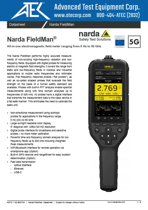
DatasheetNarda FieldManNarda FieldMan ®All-in-one electromagnetic field meter ranging from 0 Hz to 90 GHzThe Narda FieldMan performs highly accurate measure-ments of non-ionizing high-frequency radiation and low-frequency fields. Equipped with digital probes for measuring electric or magnetic field strengths, it covers the range from static and low-frequency fields in medical and industrial applications to mobile radio frequencies and millimeter waves. Flat frequency response probes (“flat probes”), as well as so-called shaped probes that evaluate the field strength on the basis of a human safety standard are available. Probes with built-in FFT analysis enable spectral measurements along with time domain analyses up to frequencies of 400 kHz. All probes have a digital interface that transmits the measurement data to the basic device in a fail-safe manner. This eliminates the need to calibrate the basic unit.›Non-directional measurement using isotropic probes for applications in the frequency range 0 Hz (DC) to 90 GHz›Large sunlight readable color display 5” diagonal with 1280x720 HD resolution›Digital probe interface for broadband and selective probes – no more meter calibration›Powerful time and frequency domain analysis for low frequency fields up to 400 kHz including Weighted Peak measurements›WiFi/Bluetooth interface for remote operation via smartphone app (Option)›Built-in GPS receiver and rangefinder for easy location determination (Option)›Fast data transmission ›optical interface ›Ethernet ›USB-CApplicationsThe Narda FieldMan is used to make precision measurements to establish human safety, particularly in workplace environments where high electric or magnetic field strengths are likely to occur. An essential task is to demonstrate compliance with generalsafety regulations, such as FCC, IEEE, ICNIRP or EMF Directive 2013/35/EU. Examples of measurement environments are:›Radiocommunication base stations (e.g. IEC / EN 62232)›Broadcasting systems (e.g. IEC 62577)›Radar and satellite communications systems ›Induction heating and melting (e.g. EN 50519)›Household appliances (e.g. IEC / EN 62233)›Electric welding equipment (e.g. IEC / EN 62822)›Railroad operations (e.g. EN 50500)›Automotive operations (e.g. IEC 62764)›Energy supply systems (e.g. IEC / EN 62110)›Electrical medical devices (e.g. IEC / EN 60601)›TEM cells and absorber chambers to demonstrate electromagnetic compatibility (EMC)Digital ProbesA large number of isotropic field probes are available for theFieldMan. All of them transmit their information and measurement data as a digital signal to the FieldMan, either via an electrical USB interface or via an optical COM interface. In this way,interference is significantly reduced compared to high-resistance analog interfaces. The specially developed screw connectors and electrical contacts are extremely robust and resilient.The probes are automatically recognized after connection to the FieldMan. Sensors inside the probe record the temperature of the measuring location and transmit it to the FieldMan display. In addition to the automatic offset correction, the temperature measurement is also used to compensate for the typicaltemperature dependency of the sensor diodes. The advantages are uninterrupted measurements without zero adjustment and higher measurement accuracy over wide temperature ranges. An automatic self-test function can even detect possible errors in the sensor system, which means that additional checking with a test generator is superfluous. Only the digital probes arecalibrated. You can continue to use your FieldMan during this time.There are probes for many different applications with theappropriate frequency and level ranges. The following table gives an overview of common areas of application.Frequency rangeDC up to1 kHzUp to400 kHzUp to400 kHz Up to 30 MHz Up to 1 GHz Up to 6 GHz Up to 40 GHz Up to 90 GHz Up to 50 GHz Field type, magnetic (H) or electric (E)H E+HHHHEEEE ShapedProbe modelsHP-01EHP-50F/G BFD-400-1 (100 cm 2) BFD-400-3 (3 cm 2) HFD-3061 HFD-0191 EFD-0391 EFD-0392 EFD-0691 EFD-0692 EFD-1891 EFD-4091 EFD-5091 EFD-6091EFD-9091EAD-5091EBD-5091ECD-5091EDD-50915G mobile radio / telecommunications Broadcast radio / TVSatellite communications RadarIndustry: Heating and temperingIndustry: Plastics weldingIndustry: Semiconductor productionMedicine: Diathermy, hyperthermyLeak locationHousehold appliances Electric welding equipmentRailroad operationsAutomotive operationsEnergy supply systems Electric medical devicesAccredited calibration includedProbe interfaceOptical connectionDigital probe interfaceFig. 1. Areas of application and suitable probe modelsUse and benefitDuring the development of the FieldMan, special attention was paid to achieving simple, well-structured and fluid operation. The arrangement of many display elements known from smartphones, the self-explanatory symbols and the FieldMan processes, which are perfectly tailored to the measurement tasks, offer maximum ease of use. The large, anti-glare HD color display shows the measured values numerically and graphically with all important additional information in a clear form and is easy to read even in bright sunlight. From simple broadband measurements to sophisticated time signal recording in real time or spectral frequency analysis of low-frequency fields, you have the right operating modes at your disposal.Measurement results can be commented on by text or voice and can be saved as a screen copy at the push of a button. Built-in sensors record the current environmental conditions as well as the position data and automatically add them to the measurement result. The built-in distance meter (option) shows you the measuring height above the ground, which makes the exact positioning of the measuring device much easier. For a better overview, the measurement results can be assigned to freely definable projects, which is particularly helpful when the measurement locations change frequently. If you want todocument your measurement results with photos and videos, the FieldMan smartphone app will help you. For example, the app wirelessly transfers media files created with the smartphone to the project directory on the FieldMan SD memory card. A newly developed, extremely powerful PC software "Narda-TSX" is available for documenting the measurement results, media and other information. It is Narda's new software platform for device configuration, measurement data evaluation and documentation, which in addition to the FieldMan will also support other Narda products in the future.Fig. 2. FieldMan display and controlsFig. 3. The FieldMan is supplied with a robust transport caseProbe connectionBrightness sensor LoudspeakerMicrophone, humidity sensor Status bar Probe information Measurement informationMeasurement isotropic Measurement single axes Statistical values Interface panelMeasurement graphic: Time curve, spectrum or bar graph Softkey symbolsSoftkeys Save key Back key Navigation keyStatus LEDDefinitions and ConditionsConditionsUnless otherwise noted, specifications apply after 30 minutes warm-up time within the specified environmental conditions. The product is within the recommended calibration cycle.Specifications with limitsThese describe product performance for the given parameter covered by warranty. Specifications with limits (shown as <, ≤, >, ≥, ±, max., min.) apply under the given conditions for the product and are tested during production, considering measurement uncertainty.Specifications without limitsThese describe product performance for the given parameter covered by warranty. Specifications without limits represent values with negligible deviations, which are ensured by design (e.g. dimensions or resolution of a setting parameter). Typical values (typ.)These characterize product performance for the given parameter that is not covered by warranty. When stated as a range or as a limit (shown as <, ≤, >, ≥, ±, max., min.), they represent the performance met by approximately 80% of the instruments. Otherwise, they represent the mean value. The measurement uncertainty is not taken into account. Nominal values (nom.)These characterize expected product performance for the given parameter that is not covered by warranty. Nominal values are verified during product development but are not tested during production. UncertaintiesThese characterize the dispersion of the values attributed to the measurands with an estimated confidence level of approximately 95%. Uncertainty is stated as the standard uncertainty multiplied by the coverage factor k=2 based on the normal distribution. The evaluation has been carried out in accordance with the rules of the “Guide to the Expression of Uncertainty in Measurement” (GUM).Specifications MetricsElectric and magnetic fieldsMeasurement control and result display for the following probes and analyzers.Frequency range and level range depending on the probe/ analyzer. Broadband probes 100 kHz to 90 GHz (see list of digital broadband probes)Selective probes 1 Hz to 400 kHz, B-field (see list of digital selective probes)Probe model EHP-50F/G 1 Hz to 400 kHz, E-field and B-field (FFT-Analyzer, see separate datasheet)Probe model HP-01 0 Hz to 1 kHz, B-field (Magnetometer/ FFT-Analyzer, see separate datasheet)Electric field units V/m, mW/cm2, W/m2, % of standard (depending on the connected probe)Magnetic field units A/m, Tesla, Gauss, mW/cm2, W/m2, % of standard (depending on the connected probe)Temperature 1Logging of the ambient temperature at the time of measurement (-40 °C to +85 °C) in °C or °F Humidity 1Logging of the ambient relative humidity at the time of measurement (0% to 100% RH)Air pressure Logging of the ambient air pressure at the time of measurement (300 to 1100 hPa)Distance (Option) An ultrasonic rangefinder on the bottom side measures the distance to ground or to an object (0.25 m to 4 m) in m, ft, in or yd. Coverage ratio ≈ Distance / 4.Geolocation (Option) Built-in GNSS receiver for determining latitude, longitude and altitude (MSL).72 channels with the support of GNSS systems (GPS / QZSS, Galileo, GLONASS, BeiDou) and the SBAS extension system (WAAS, EGNOS, MSAS, GAGAN).Position accuracy: Autonomous 2.5 m CEP.DisplayDisplay type Sunlight readable 5” color TFT-LCD anti-glare display (HD 1280 x 720 pixels) Brightness Manual control or automatic control via brightness sensorOperating languages Largely language-independent measurement control via symbols.Menu languages: English, German, more are planned.1 The permissible operating range of the device and probe must not be exceeded. The temperature sensor is located in the probe.Operating ModesMode description Field Strength Broadband field measurements. Numerical results with time curve or bar graph display.Spatial Average Procedure for spatial averaging of broadband measurements over several measurement positions. Timer Logging Time-controlled broadband measurement of the field strength in a definable period.Spectrum FFT analysis with spectrum display, marker evaluation and display of the broadband level. Shaped Time Domain Time domain assessment (WPM, WRM) with digital filtering related to a selected safety limit. Scope Triggered measurement of the field curve over time with pretrigger feature.Available modes Broadband ProbesDigital Interface100 kHz to 90 GHzSelective ProbesDigital Interface1 Hz to 400 kHzModel EHP-50F/GOptical Interface1 Hz to 400 kHzModel HP-01Optical InterfaceDC to 1 kHzField Strength ☑☑☑☑Spatial Average ☑☑☑☑Timer Logging ☑☑☑☑Spectrum ☑☑☑Shaped Time Domain ☑☑Scope ☑FeaturesProbe features Recognition Probes are automatically recognized after being plugged in.Operating principle Measurement signals are sampled and processed inside the probe and provided as digital values. Offset compensation Automatic offset compensation enables gapless RF measurements without zero adjustment.Self-test Functional test including the sensor function of each measuring axis for digital interface probes.Signal detection RMS detection, Peak detection for WPM measurementsand selectable detection RMS/Peak with BDF-400 probes.Numerical display Total field (isotropic) and field components X, Y, Z (for probes up to 18 GHz).Result types Field Strength Actual, Max, Min, Avg (average) and Max Avg Spectrum Actual or Max or AvgShaped Time Domain Actual, Max and MinScope Actual, Max and marker for dB/dtAverage mode Moving average over time of the square values of the field strength.Averaging time Field Strength,Timer Logging 1 s, 3 s, 10 s, 30 s, 1 min, 3 min, 6 min, 10 min, 30 min, 1 h, 6 h, or 24 h Spectrum 4, 8, 16, 32 or 64 number of averagesGraphical display with marker function Field Strength Actual and Avg trace vs. time, time span selectable from 48 s to 24 hours.Spatial Average Bar graph of results for each measurement position (≤100) and the spatial average line. Timer Logging Timeline during measurement, results as a graph vs. time after measurement.Spectrum Frequency spectrum and selectable limit line. All axes are measured, one can be displayed. Shaped Time Domain Exposure index (WPM or WRM) in % vs. time, time span selectable from 4 min to 24 h. Scope Sign-based recorded signal with 25 % pretrigger. Recording time selectable from 1 ms to 30 s.Screenshots Manually initiated screenshot or automatically when saving a measurement result.Comments Voice and/or text comments can be assigned to a measurement result.Alarm Alarm sound and alarm message when an adjustable field strength is exceeded.Audible field indicator Acoustic hotspot search with field strength-dependent audio frequency (available for RF-probes).Scheduled measurements Mode Timer Logging with automatic wake-up and shutdown after measurement. Start time pre-selection: up to 24 h or immediate startTimer duration: up to 100 hStorage interval: 1s to 6 min (in 11 steps, up to 32000 intervals)Correction factors Post-processing for broadband probes to increase the accuracy at a known field frequency(direct frequency entry, interpolation between calibration points)Probe interface Digital probe interface for direct connection or via the optional extension cable.Optical port Serial, full duplex, ≥ 1 Mbit/s, to connect the Field Analyzer EHP-50F/G, the Magnetometer HP-01or the Digital Probe Repeater. Recommended interface for PC controlled measurements.USB 2.0 USB-C connection for battery charging, remote control and data transfer.Ethernet Gigabit Ethernet LAN connectivity for remote control and data transfer.Bluetooth (Option) BT 4.0 for remote control via smartphone app (Android).WiFi (Option) WLAN connectivity for remote control and data transfer.AUX MMCX connector, reserved for future use.Result StorageStorage triggers Manual (by keypress) or scheduled (Timer Logging Mode).Storage medium Removable micro SD card for storing measurement data, setups and comments.Storage capacity Up to 128 GB.16 GB micro SD card included.Screenshots Screenshots can be saved for documentation as PNG files.Voice recorder Voice comments can be added to measurement results (recording and playback).Text editor Text comments can be added to measurement results (integrated virtual keyboard).Photos / videos (WiFi/BT Option) Photos and videos from a smartphone can be transferred to the device using the FieldMan app.Printouts (WiFi/BT Option) Saved measurement results can be printed locally by using the FieldMan Android app for on-sitedocumentation (requires a compatible wireless printer).General SpecificationsRecommended calibration interval Calibration of the basic unit is not required. Only the probes are calibrated.Power supply internal Li-Ion rechargeable battery pack, included and replaceable external USB-C PD (maximum 12 V / 3A, compatible with BC1.2 and QC 3.0)Operating time (nom.) 16 hours (with broadband probes and analyzers)Charging time (nom.) 4 hours (80% charged in 2½ h)RF Immunity 200 V/m (100 kHz to 60 GHz); can be below the permissible measuring range of a probe. Operation in static magnetic fields ≤ 30 mT (to avoid high force on the device)Dimensions (H x W x D) 51 mm x 93 mm x 312 mm without probeWeight 695 g (without probe)Country of origin GermanyEnvironmental ConditionsRange of application Suitable for outdoor use and an operating altitude of up to 5000 mOperating temperature -20 °C to +50 °C during normal operation with battery0 °C to 40 °C during the charging process with an external chargerHumidity < 29 g/m³ (< 93 % RH at +30 °C), non-condensingIngress protection IP54 (probe screwed on, protective flap closed, stand folded in)Climatic conditions Storage 1K4 (IEC 60721-3) extended to -30 °C to +70 °C (battery removed)1K3 (IEC 60721-3) extended to -20 °C to +50 °C (battery inserted) Transport 2K3 (IEC 60721-3) extended to -30 °C to +70° COperating 7K2 (IEC 60721-3) extended to -20 °C to +50 °CMechanical conditions Storage 1M3 (IEC 60721-3) Transport 2M3 (IEC 60721-3) Operating 7M3 (IEC 60721-3)EMC European Union Complies with Directive 2014/53/EU, EN 301489-1, EN 301489-17 and EN 61326 -1 Immunity IEC/EN: 61000-4-2, 61000-4-3, 61000-4-4, 61000-4-5, 61000-4-6, 61000-4-8, 61000-4-11 Emissions IEC/EN: 61000-3-2, 61000-3-3, IEC/EN 55011 (CISPR 11) Class BSafety Complies with European Low Voltage Directive 2014/35/EU and IEC/EN 61010-1 Material Complies with European RoHS Directive 2011/65/EU and (EU)2015/863ORDERING INFORMATIONInstrument SetsDescription Part number FieldMan Basic Set-Probes are not included –Includes:›FieldMan Basic Unit›Hard Case for FieldMan and up to 5 Probes ›Power Supply USB-C PD, AU/EU/UK/US Plugs ›Cable, 2x USB-C(M), 3 A, 2 m›Shoulder Strap, 1 m ›Marking Rings for FieldMan Probes›Quick Start Guide›Safety Instructions›USB Stick: Manuals and Documents›Software Narda-TSX (free download)2460/101Digital Broadband ProbesDescription Part number Probe HFD-3061, H-Field, 300 kHz–30 MHz 2462/05 Probe HFD-0191, H-Field, 27 MHz–1 GHz 2462/06 Probe EFD-0391, E-Field, 100 kHz–3 GHz 2462/01 Probe EFD-0392, E-Field, High Power, 100 kHz–3 GHz 2462/12 Probe EFD-0691, E-Field, 100 kHz–6 GHz 2462/14 Probe EFD-0692, E-Field, 600 MHz–6 GHz 2462/20 Probe EFD-1891, E-Field, up to 18 GHz2462/02 Probe EFD-4091, E-Field, up to 40 GHz 2462/19 Probe EFD-5091, E-Field, 300 MHz–50 GHz, Thermocouple2462/03 Probe EFD-6091, E-Field, 100 MHz–60 GHz2462/17 Probe EFD-9091, E-Field, 100 MHz–90 GHz2462/18 Probe EAD-5091, FCC 1997 Controlled, Shaped, 300 kHz–50 GHz, E-Field 2462/07 Probe EBD-5091, IEEE 2019 Restricted, Shaped, 3 MHz–50 GHz, E-Field 2462/21 Probe ECD-5091, SC 6 2015 Controlled, Shaped, 300 kHz–50 GHz, E-Field 2462/16 Probe EDD-5091, ICNIRP 2020 Occ, Shaped, 300 kHz–50 GHz, E-Field 2462/22 Note: Separate data sheets are available for the probesDigital Selective ProbesDescription Part number Probe BFD-400-1, B-Field, 100 cm2, 1 Hz–400 kHz, selective 2463/01 Probe BFD-400-3, B-Field, 3 cm2, 1 Hz–400 kHz, selective2463/02 Note: Separate data sheets are available for the probesField AnalyzersDescription Part number EHP-50F E&H Field Analyzer Set, 1 Hz–400 kHz (no Transport Case included) 2404/105 EHP-50F E&H Field Analyzer Set, 1 Hz–400 kHz, Stand-alone/PC use 2404/104 HP-01 Magnetometer Set DC–1 kHz 2405/101OptionsDescription Part number Option, Narda-TSX Live Measurements, for FieldMan Digital Probes (expected from Q3 2023) 2460/95.01 Option, GPS/ Range Finder for FieldMan 2460/95.11 Option, WiFi/ Bluetooth for FieldMan (expected from Q4 2023) 2460/95.12AccessoriesDescription Part number Digital Broadband Probe Repeater 2464/01 Test-Generator 27 MHz 2244/90.38 Tripod, Non-Conductive, 1.65 m, with Carrying Bag 2244/90.31 Tripod, Benchtop, 0.16 m, Non-Conductive 2244/90.32 Tripod Extension, 0.50 m, Non-Conductive (for 2244/90.31) 2244/90.45 Handle, Non-Conductive, 0.42 m 2250/92.02 Car Charger Adapter, USB-C PD 2259/92.28 Cable, Digital Probe Extension, 2 m 2460/90.02 Cable, Digital Probe to USB 2.0 (Type A), 3 m 2460/90.03 Cable, FO Duplex (1000 µm) RP-02, 2 m 2260/91.02 Cable, FO Duplex (1000 µm) RP-02, 5 m 2260/91.09 Cable, FO Duplex (1000 µm) RP-02, 10 m 2260/91.07 Cable, FO Duplex (1000 µm) RP-02, 20 m 2260/91.03 Cable, FO Duplex (1000 µm) RP-02, 50 m 2260/91.04 Cable, FO Duplex, F-SMA to RP-02, 0.3 m 2260/91.01 O/E Converter RS232, RP-02/DB9 2260/90.06 O/E Converter USB, RP-02/USB 2260/90.07 Cable, Adapter USB 2.0 - RS232, 0.8 m 2260/90.53Narda Safety Test Solutions GmbH Sandwiesenstrasse 772793 Pfullingen, GermanyPhone +49 7121 97 32 0****************** Narda Safety Test SolutionsNorth America Representative Office435 Moreland RoadHauppauge, NY11788, USAPhone +1 631 231 1700******************Narda Safety Test Solutions S.r.l.Via Benessea 29/B17035 Cisano sul Neva, ItalyPhone +39 0182 58641****************************Narda Safety Test Solutions GmbHBeijing Representative OfficeXiyuan Hotel, No. 1 Sanlihe Road, Haidian100044 Beijing, ChinaPhone +86 10 6830 5870********************® Names and Logo are registered trademarks of Narda Safety Test Solutions GmbH - Trade names are trademarks of the owners.。
SQL存储过程实现相似重复记录检测摘要:“相似重复记录检测”是数据清洗要解决的主要问题之一,对于提高数据质量及决策可靠性起到关键作用。
编写SQL存储过程脚本实现了一种相似重复记录检测算法——PCM算法,测试了算法性能,针对PCM算法时间复杂度较高的缺陷,提出了利用SQL语句优化技术改进算法执行效率。
关键词:SQL;存储过程;相似重复记录;数据清洗0引言随着数据库技术的发展及应用,各领域历史数据量越来越庞大,建设领域相关的决策支持系统以有效利用历史数据成为普遍关注的热点课题。
其中,数据清洗算法的研究倍受关注,对于提高数据质量进而提高决策的可靠性起到关键作用。
数据清洗一般包括“相似重复记录检测”、“空值处理”、“数据异常检测”和“地址日期型错误检测”4个需要解决的问题。
参考文献[1-5]提供了多种相似重复记录检测算法研究,其中参考文献[1]借鉴生物学DNA序列比对法将位置编码技术引入到数据清洗环节中,提出了一种相似重复记录检测算法PCM(Position-Coding Method,位置编码方法)。
由于SQL存储过程具有实现数据封装、隐藏以及代码的预编译、减少网络负载、维护方便等优点,所以被许多RDBMS和编程工具所支持,本文作者编写SQL存储过程实现了PCM算法,并对算法性能进行了测试。
针对该算法时间复杂度较高的缺点,提出可以应用SQL语句优化技术对SQL 存储过程脚本进行优化以提高算法执行效率,作为后续研究工作。
1相似重复记录检测相似重复记录检测是数据清洗要解决的主要问题之一。
比如,很多公司为了推广新产品,会通过邮件列表系统定期向客户邮寄广告册或试用品,此时要求邮件列表记录干净、准确并且不存在相似重复的邮件地址,否则可能会增加不必要的广告成本。
1.1相似重复记录所谓相似重复记录是指客观上表示现实世界中的同一实体,但由于表示方式不同或拼写问题而使DBMS不能识别其为重复的记录。
这些重复的记录可能导致建立错误的数据挖掘模型,降低后期决策的可靠性。
Keysight TechnologiesUsing BenchVue Test Flow to CreateTest Sequences without ProgrammingApplication NoteIntroductionKeysight BenchVue software lets you connect, control and capture data from your choice of an ever-growing list of supported Keysight instruments—digital multimeters, oscilloscopes, power supplies, functiongenerators, and RF signal sources and analyzers, just to name a few. The BenchVue Test Flow applicationallows you to create sequences of setups and measurements, all without having to write a computerprogram. This application note explains some of the many things you can do with the Test Flow application, including:–Dragging and dropping instrument settings and retrieving measurements into a sequence–Creating loops, delays, prompts, and simple “if-then” conditions–Using mathematical operations–Automatically exporting data and images to Microsoft Excel, MATLAB, CSV or Microsoft Word files–Controlling equipment not on the BenchVue supported instrument list–Using instrument commands not already built in to BenchVueExample: Powering up a boardSuppose you want to power-up a circuit board and perform some basic measurements. You might want toapply power, wait a short time for circuit elements to stabilize, measure the current drain, and immediatelystop if the current drain is too high, also outputting a warning message. With Test Flow, this is an easy task.Figure 1 shows a Power Supply Application running on the left side of the BenchVue screen and an emptyTest Flow sequence workspace on the right. A long downward arrow labeled “Flow” tells you that execution will be from top to bottom. Anything that can be “automated” (i.e., used in Test Flow) is highlighted by anorange rectangle. Any object placed into the test sequence is called a “block.” The run controls are at thebottom of the Test Flow pane and in the following order from left to right: Start, Single Step and Stop:Figure 1. Power Supply Application (left panel) and a blank Test Flow sequence (right panel).To start creating a sequence, left click on one of the orange boxes and drag it into the sequenceworkspace as shown in Figure 2. When you drop it, a dialog box pops up that lets you choosewhat kind of operation you want to do: Set a value, Get a value, create a List of values, orcreate a Sweep of values. Some boxes offer fewer choices, such as Set and Get only, and allmeasurements are only of the “Get” type. Some blocks do not offer a choice.Figure 2. A “Voltage Setting” block can be dragged into the Test Flow workspace and its type chosen (e.g., “Set,” in this case). To have the supply output a voltage, its output must be turned on. To do this, drag the “On/Off”button ( ) into the Test Flow sequence and change its state from Off to On. Note that noactual state changes occur on the instrument as you do this. Finally, measure the current drainby dragging the “Measure(I)” box into the sequence.Figure 3. When an instrument application is run, it is given a number starting at 1. That number is shown above the sequence and in each step that uses that instrument.Once an operation from an application is placed in the Test Flow sequence, a picture of theinstrument is shown above the sequence. Its position (e.g., 1, 2, 3, 4) is also shown. Each stepthat accesses that instrument refers to that number as shown in Figure 3.Figure 4. This is a ready-to-run sequence that sets a power supply to 5 V, turns on its output and measuresthe resulting current.The sequence to this point is shown in Figure 4. Although it could be run, no delays have yetbeen added. One way to add a delay is to use the gear icon that is present in many blocks.Some blocks provide a way to specify a delay that will be applied after each step, as shown inFigure 5. Another way to do this is to add a Delay Block. This block is kept in a section called“More Blocks,” located to the left of the main sequence. Figure 6 shows all other groups ofblocks that are available—basic, loops, variables, math, and advanced.Figure 5. Clicking the gear icon in a block brings up a dialog box that allows you torename it, change its color, save any data that might be gathered, and apply a delayafter the step is executed. In this case, a 25-ms delay is used to make sure circuitelements have stabilized before the sequence continues.Figure 6. More Blocks tool bar.The Basic Blocks section contains a Delay block which can be used if a more “visible” delay isdesired than the one inside the gear icon. Finally, if the current drain was higher than desired, it might be desirable to output a prompt telling the user that the current was too high and to shut off the supply output. In this case, you can use an “If-Then-Stop” block, which allows you toplace one or more conditions in the “If” section, and then choose what to do if the condition ismet, whether run additional blocks and halt, or halt immediately (Figure 7).Now suppose that the circuit-under-test had a DC output that required execution to pause until the measured voltage was greater than 4 V. One way to do this would be to use the “Wait Until” block, using a digital multimeter (DMM) measurement for the exit condition. First start theDMM application and drag some setup properties over to the Test Flow workspace. Then make a measurement repeatedly until the result is greater than 4 V, as shown in Figure 8. Note thatthis could run forever if the circuit is defective and the voltage never goes above 4 V!Figure 7. A 500-ms delay is added to allow circuits to stabilize. An “If-Then-Stop” block tests the currentand execution stops if too much current is drawn.If the condition(s) are met, the Promptand the Set Ch1 On/Off blocks willexecute. In this case, when thesequence was run, the measuredcurrent was 10 mA, which is OK, so thesequence continued.When blocks contain conditions that are to be tested, such as in Figure 8 where Wait-Untiland If-Then-Stop blocks are used, it is possible to use more than one condition. Suppose, forexample, that in addition to a voltage measurement, it was desirable to wait until a certain ACsignal frequency was greater than 100 kHz. Starting the oscilloscope application, a frequencymeasurement could also be dragged into the list of conditions. The choice can then be made as to whether ALL of the conditions must be true or ANY of the conditions must be true, as shown in Figure 9 and the close-up view of this block in Figure 10.Figure 8. Example of the use of the Wait-Until block.Figure 9. An oscilloscope measurement AND a DMM measurement are both used as conditions for testing to continue.Figure 10. A close-up view of a block with multiple exit conditions. Note that measurements on thehardware are taken repeatedly until the exit conditions are true.LoopsFigure 11 shows the various loops that are available in Test Flow. These cause the blocks inside to be run for a given Count, time (Duration), While conditions are true, or Until conditions become true. There is also a Forever loop that will run until the sequence is either aborted by an If-Then-Stop block or manually stopped.Figure 11. Loop blocks.VariablesIn the examples above, measurements such as “Get CH1 Current Measurement” havebeen dragged into test conditions where they can be used only once (i.e., any data that the measurement returns can’t be used for any other tests). Sometimes it’s desirable to take a reading and use it for more than one condition. For example, you might want to make sure that a single reading is greater than 4.75 V and less than 5.25 V. This can be done by creating variables, as shown in Figure 13. In this case, two variables were created by clicking the Create Variable button and naming them “volts” and “frequency.” The variables were dragged into the sequence and then the relevant measurement was dragged into the right side of the equation. The voltage measurements were made using a power supply and the frequency measurements were made using an oscilloscope.Note that there are two choices for variables: Set or Output (Shown in Figure 12). Set provides a way to assign a variable to a quantity (e.g., a measurement, an instrument setting, another variable, or a constant), but it does not maintain the units (e.g., “V” or “A”) that may be associated with the right side of the equation. The “Output” block outputs the variable to the results table and allows units to be attached to the value.Figure 12. There are two choices for variables: Set or Output.An If-Then-Stop block was chosen to use the two variables. By selecting Any at the top of the block, the Halt condition will be met if the voltage is outside the range 4.75 to 5.25 V, or the frequency is outside the range 90 to 110 kHz.Figure 13. Variables “volts” and “frequency” can be created and used instead of real-time measurements.Math BlocksFigure 14. Math functions and constants.There are many ways to create mathematical expressions in Test Flow. Figure 14 shows the available functions. These can be nested and used with variables or directly with measurements.For example, suppose you are measuring voltage and current from two DMMs simultaneously and want to compute power in dBm. Figure 15 shows exactly what this would look like.Figure 15. Here, one DMM (instrument #4) takes an AC voltage reading and puts the result into the variable “volts.” The other DMM (instrument #2) takes an AC current reading and puts the result into the variable “current.” The two variables, volts and current, are then dragged into the multiplication block, assigned the value “W” (for Watts). Next, that math function is dragged into the unit conversion block “dBm <- W.” When the sequence is run, actual values are shown in each block.Figure 16. SCPI block example.SCPI BlocksThe applications that are provided with BenchVue are meant to provide coverage of the most commonly used functions of BenchVue supported instruments. In some applications; however, there are settings that are not implemented. The SCPI (Standard Commands for Programmable Instruments) block allows you to get around that limitation by sending and receiving commands in the native language of the instrument—SCPI (pronounced “skippy”). You can still drag and drop other commands from an application directly into the Test Flow sequence, and then add additional SCPI commands to do more advanced operations.For example, the Function Generator application has no way to cause a manual trigger on a 33500A or 33600A True form waveform generator. But the SCPI command for a trigger is “*TRG.” Figure 16 shows what it would look like to send this command in a Test Flow sequence.The Address field allows you to select any instrument that has been discovered. This means that it can be used on unsupported or non-Keysight instruments, as long as they use SCPI, as well as supported instruments. In Figure 16, notice that there is a Validate button on the side. This can be used to test the SCPI command immediately without running the entire sequence. This button sends the command, followed by a “SYST:ERR?” query. Consequently, if you are using this command with unsupported instruments not made by Keysight, you must make sure that the “SYST:ERR?” command is supported. This error check is also run when the SCPI block is executed during a normal run of a Test Flow sequence. If that is not desirable, it can be turned off by unchecking the box in the gear icon labeled “Clear Errors.”SCPI commands that return data from an instrument always have “?” as the last character. When the SCPI block sees “?,” it allows the selection of several data types: Boolean, Double, String (the default), Image, Double Array and Byte Array. Consult the manual for the instrumentyou are using to see what data type to select.When getting images from your instrument, note that the image data type requires that the data be in “IEEEBinaryType.BinaryType_UI1” format. A .bmp file is created as a result of executing this block.Command ExpertSometimes you might need to send a sequence of SCPI commands or may not know what those commands are. If you are unsure of which commands to use with various instruments, you can use Keysight’s Command Expert software to help you create commands or command sequences that can then be exported to many programming languages. In BenchVue, the sequence can be created and then brought into Test Flow.Figure 17. Last portion of a Command Expert sequence that sets up four 34401A DMMs for simultaneous readings. By starting this from Test Flow and then clicking “Export to Add-On,” the sequence becomes part of Test Flow.Consider the following example of how to work around a common Keysight 34401A DMM challenge—the inability to use the external trigger in BenchVue. Assume it was desired to externally trigger four 34401A DMMs from a function generator and then bring the data back into Test Flow where it could be exported to Excel and plotted. Since these particular DMMs prevent further communication until all readings have been fetched, all four were set up to expect 512 readings, and additional SCPI commands were sent to configure the DMMs correctly for this test, followed by an “INIT” command to place each DMM into a wait-for-trigger state. Finally, a “FETC?” command was issued to all four DMMs sequentially to extract their readings. Figure 17 shows how the last portion of the sequence looks in Command Expert. Figure 18 shows how the Command Expert block is built in BenchVue to return the readings.Figure 18. A completed sequence that has returned variables looks like this screen capture. Variables rdgs1-4 were created and then dragged into the block.In Test Flow, the readings were put into four variables and all result data was exported to Excel using the export block. The data from each of the DMMs can be seen in the Results Table View in Figure 19 to the right of the Test Flow workspace. All steps that return data are shown here. Double clicking on the Trace Data icon brings up a chart of the data that can then be exported to Excel, Word, CSV, or MATLAB. In this example, a sine wave was fed into the four DMMs,so all charts are identical. Exports can also be included in the sequence so that this action is perormed automatically using the “Export” block.Figure 19. Result data is stored in a table. Click the Trace Data icon to pop up the trace data for export. An “Export” block in Test Flow is also available if the data is to be exported automatically from the test sequence.A video of this experiment, as well as other BenchVue videos is available at/find/BenchVue_videos.More information about Command Expert can be found at/find/commandexpert.Figure 20. Line chart showing values of data and setup information at each execution step.Chart DataAnother feature of Test Flow is the Chart windows. The Results table in Figure 19 can also beseen graphically in the Line Chart view, as shown in Figure 20.Select X-Y Axes for Custom ViewsAn X-Y chart, in which X and Y axes are independently chosen, can be generated by Test Flow. Multiple overlays with different sets of data can also be plotted if desired. Figure 21 shows an example of a transistor curve tracer chart that was made by selecting X and Y axis values (in this case collector current and collector voltage) and a value (base current) that selects which group of X-Y data is to be plotted.Figure 21. X-Y chart constructed from multiple measurements.Screen and Trace Data CaptureSome BenchVue apps can capture images and trace data. If the feature is enabled for use in Test Flow (i.e., it has an orange rectangle around it), then it can be dragged into the Test Flow workspace. When the sequence runs, a Trace Data or Screen Capture icon is placed into the Results table. Clicking on the icons cause the images or trace data to pop up, where they can be exported (Figure 22). Or, you can use the Export block to export this data as part of the automated sequence.Figure 22. Screen and trace captures can be automated into Test Flow sequences.ConclusionAs this application note has shown, there are many things you can do with BenchVue’s Test Flow application to save time and achieve faster results—all without ever having to write a computer program. The intuitive drag-and-drop interface in Test Flow enhances your work flow with the ability to create custom, automated test sequences; a task that used to require days using traditional programming languages. Moreover, you can obtain a deeper understanding of your data using Test Flow’s built-in analysis tools, which log and graph with selectable x-axis and y-axis formats and much more.For more Test Flow application details and examples, go to/find/BenchVueTestFlow.For more information about Keysight’s BenchVue software, refer to/find/BenchVue.This information is subject to change without notice.© Keysight Technologies, 2016Published in USA, August 11, 20165992-1690ENEvolvingOur unique combination of hardware, software, support, and people can help you reach your next breakthrough. We are unlocking the future of technology.From Hewlett-Packard to Agilent to KeysightmyKeysight/find/mykeysightA personalized view into the information most relevant to /find/BenchVueTest FlowFor more information on KeysightTechnologies’ products, applications or services, please contact your local Keysight office. The complete list is available at:/find/contactus Americas Canada (877) 894 4414Brazil 55 11 3351 7010Mexico001 800 254 2440United States(800) 829 4444Asia Pacific Australia 1 800 629 485China800 810 0189Hong Kong 800 938 693India 1 800 11 2626Japan 0120 (421) 345Korea 080 769 0800Malaysia 1 800 888 848Singapore 180****8100Taiwan0800 047 866Other AP Countries (65) 6375 8100Europe & Middle East Austria 0800 001122Belgium 0800 58580Finland 0800 523252France 0805 980333Germany ***********Ireland 1800 832700Israel 1 809 343051Italy800 599100Luxembourg +32 800 58580Netherlands 0800 0233200Russia 8800 5009286Spain 800 000154Sweden 0200 882255Switzerland0800 805353Opt. 1 (DE)Opt. 2 (FR)Opt. 3 (IT)United Kingdom0800 0260637For other unlisted countries:/find/contactus(BP-06-08-16)Learn more at/find/software Start with a 30-day free trial./find/free_trialsDownload your next insightKeysight software is downloadableexpertise. From first simulation through first customer shipment, we deliver the tools your team needs to accelerate from data to information to actionable insight. –Electronic design automation (EDA) software–Application software–Programming environments –Productivity software。
Proving the Safety of SQL QueriesAbstract:Many programs need to access data in a relational database. This is usually done by means of queries written in SQL. Although the language SQL is declarative, certain runtime errors are possible. Since the occurrence of these errors depends on the data, they are not easily found during testing. The question whether a query is safe can be reduced to a consistency check. It is well known that consistency is in general undecidable, and that this applies also to SQL queries. However, in this paper, we propose a consistency check that can handle a surprisingly large subset of SQL (it uses Skolemizationwith sorted Skolem functions, and a few other tricks). This consistency check is also the basis for generating other semantic warnings. Furthermore, it can be used to generate test data for SQL queries.Keywords:SQL, Runtime Errors, Consistency.1. IntroductionProbably a large percentage of the software that is developed today uses data stored in a relational database. The database is normally accessed with statements in the language SQL, especially queries. Although is a declarative language, there are situations in which errors might occur at runtime that depend on the data.2. Possible Runtime Errors in SQLAs explained in the introduction, if the INTO-clause is used for storing the query result in program variables, the query must never return more than one row. Suppose the given query is:SELECT t1, . . ., tk INTO v1, . . ., vk FROM R1 X1, . . ., Rn Xn WHERE ϕIn order to make sure that there are never two solutions, we duplicate the tuple variables and check the following query for consistency. If it is consistent (including the constraints, see Section 3.3), a runtime error can occur, and the constructed model givesan example:SELECT * FROM R1 X1, ..., Rn Xn,R1 X_1 , ..., Rn X_n WHERE ϕ AND ϕ AND (X1= X_1 OR ···OR Xn _= X_n )The formula ϕ_ results from ϕ by replacing each Xi by X_i . We use Xi _= X_i as an abbreviation for requiring that the primary key values of the two tuple variables are different (we assume that primary keys are always NOT NULL). If one of the relations Ri has no declared key, it is always possible that there are several solutions(if the condition ϕ is consistent).If the given query uses “SELECT DISTINCT”, one needs to add a test that the result tuples differ:(t1 _= t_1 OR ···OR tk _= t_kOR t1 IS NULL AND t_1 IS NOT NULLOR t_1 IS NULL AND t1 IS NOT NULL. . .OR tk IS NULL AND t_k IS NOT NULLOR t_k IS NULL AND tk IS NOT NULL)The same problem can occur with conditions of the form A = (SELECT ...) inside a query: Whenever a subquery is used as scalar expression, it must not return multiple rows. If the subquery is non-correlated(i.e. does not access tuple variables from the outer query), we can use exactly the same test as above. If the query is correlated, it might not be completely clear what knowledge from the outer condition should be used (as usual for runtime errors, evaluation order becomes important here). In order to be safe, we propose to ignore the outer condition. Let the subquery have the form:SELECT t FROM R1 X1, . . ., Rn Xn WHERE ϕIf it accesses the tuple variables S1 Y1, . . ., Sm Ym from the outer query, we would require that the following query is inconsistent (after adding the constraints):SELECT * FROM R1 X1, ..., Rn Xn, R1 X_1 , ..., Rn X_n , S1 Y1, ..., Sm Ym WHERE ϕ AND ϕ_ AND (X1 _= X_1 OR ···OR Xn _= X_n )3. Inconsistent ConditionsIn this section, we present an algorithm for detecting inconsistent conditions in SQL queries. A trivial example of an inconsistent query isSELECT * FROM R WHERE A=1 AND A=2.Since the problem is in general undecidable, we can handle only a subset of all queries. However, our algorithm is reasonably powerful and can decide the consistency of surprisingly many queries.To be precise, consistency in databases means that there is a finite model, i.e. a relational database state(sometimes called a database instance), such that the query result is not empty.In this paper, we assume that the given SQL query contains no data type operations, i.e. all atomic formulas are of the form t1 θt2 where θis a comparison operator (=, <>, <, <=, >, >=), and t1, t2 are attributes (possibly qualified with a tuple variable) or constants (literals). Null values and IS NULL are treated in Section 3.5, before that, they are excluded. Aggregations and LIKE-conditions are not treated in this paper, they are subject of our future research.3.1. Conditions Without SubqueriesIf the query contains no subqueries, the consistency can be decided with methods known in the literature, especially the algorithms of Guo, Sun and Weiss [8].The condition then consists of the above atomic formulas connected with AND, OR, NOT. We first push negation down to the atomic formulas, where it simply “turns around” the comparison operator. In t his way, NOT is eliminated from the formula. Then, we translate the formula in disjunctive normal form: ϕ1 ∨···∨on is consistent if at least one of the it is consistent. Now a conjunction of the above atomic formulas can be tested for satisfiability with the method of [8]. They basically create a directed graph in which nodes are labeled with “Tuplevariable.Attribute” (maybe a representative for an equivalence class with respect to =) and edges are labeled with < or ≤. Then they compute an interval of possible values for each node. Note that SQL data types likeNUMERIC(1) also restrict the interval of possible values.Unfortunately, if there is only a finite number of values that can be assigned to nodes, inequality conditions (t1 <> t2) between the nodes become important and can encode graph-coloring problems. Therefore, we cannot expect an efficient algorithm if there are many <>- conditions. Otherwise, the method of [8] is fast. (However, the DNF transformation that we apply before [8] can lead to an exponential increase in size.)3.2.Integrity ConstraintsThe above algorithm constructs just any model of the query, not necessarily a database state that satisfies all constraints. However, it is easy to add conditions to the query that ensure that all constraints are satisfied. For instance, consider this constraint on GRADES:CHECK(POINTS >= 0)Then the following condition would be added to each query that references GRADES:AND NOT EXISTS (SELECT * FROM GRADES WHERE NOT(POINTS >= 0)) The original query is consistent relative to the constraints if this extended query is consistent. Note that pure “for all” constraints like keys or CHECK-constraints do not need nested subqueries and thus never endanger the termination of the method. No new Skolem functions are constructed, the conditions are only instantiated for each existing Skolem term of the respective sort (relation). This is also what one would intuitively expect. Foreign keys, however, require the existence of certain tuples, and therefore might sometimes result in an infinite set TQ. This is subject of the next section.3.3 Restrictions and Possible SolutionsThe main restriction of our method is that the set TQ must be finite, i.e. no tuple variable over a relation R may depend directly or indirectly on a tuple variable over the same relation R. This is certainly satisfied if there is only a single level of subqueries.However, GRADES has a foreign key ENO that references EXERCISES. This can be enforced in models by adding the following condition to all queries:AND NOT EXISTS (SELECT * FROM GRADES C WHERE NOT EXISTS (SELECT * FROM EXERCISES P WHERE P.ENO = C.ENO))We now get a Skolem function fP : GRADES →EXERCISES. In itself this would be no problem, and actually there will never be a problem if the foreign keys are not cyclic and the query itself contains only a single level of NOT EXISTS. But in Example 1, the query introduces the Skolem function fG : EXERCISES →GRADES.Together we can now generate infinitely many terms: fE1, fG(fE1), fP(fG(fE1)), fG(fP(fG(fE1))), and so on. However, it is easy to prove that fP(fG(fE1)) = fE1: We know thatfG(fE1).ENO = fE1.ENO andfP(fG(fE1)).ENO = fG(fE1).ENO.Since ENO is key of EXERCISES, the two tuples must be the same, and thus a finite TQ suffices. One case that is not solved is cyclic (recursive) foreign keys. Because of the undecidability, this problem can in general not be eliminated. However, one could at least heuristically try to construct a model by assuming that, e.g., 2 tuples in the critical relation R suffice. Then TQ(R) would consist of two constants and one would replace each subquery declaring a tuple variable over R by a disjunction with these two constants. For relations not in the cycle, the original method could still be used. If the algorithm of Section 3.1 constructs a model, the query is of course consistent. If no model is found, the system can print a warning that it cannot verify the consistency. At user option, it would also be possible to repeat the step with more constants.4. Related WorkAs far as we know, there is not yet a tool for checking given SQL queries for semantic errors independently of example database states. There are a few papers about testing SQL queries, though (e.g. [13, 12]).Of course, for the problem of detecting inconsistent conditions, a large body of work exists in the literature. In general, all work in automated theorem proving can be applied (see, e.g., [4]). The problem whether there exists a contradiction in a conjunction of inequalities is very relevant for many database problems and has been intensively studiedin the literature. Klug’sclassic paper [10] checks for such inconsistencies but does not treat subqueries and assumes dense domains for the attributes. The algorithm in [9] can handle recursion, but only negations of EDB predicates, not generalNOT EXISTS subqueries. A very efficient method has been proposed by Guo, Sun, and Weiss [8]. We use it here as a subroutine. Our main contribution is the way we treat subqueries. Although this uses ideas known from Skolemization, the way we apply it combined with analgorithm like [8], apply the relations as sorts, and detect equal terms in the Herbrand universe seems new.We also can handle null values. Consistency checking in databases has also been applied for testing whether a setoff constraint is satisfiable. A classic paper about this problem is [3]. They give an algorithm which terminates if the constraints are finitely satisfiable or if they are unsatisfiable,which is the best one can do. However, the approach presented here can immediately tell whether it can handle the given query and constraints. Also in the field of description logics, decidable fragments of first order logic are used. Recently Minock [11] defined a logic that is more restricted than ours, but is closed under syntactic query difference.Consistency of database queries has also connections to semantic query optimization (see, e.g., [5]), and cooperative query answering (see, e.g., [7, 6]). However, in semantic query optimization, only relatively simple consistency checks can be used for efficiency reasons(optimization time must be amortized during later execution).In cooperative query answering, a database state is given: The system does not really notice that the query is inconsistent, only that it yields an empty answer in the current state. In both fields, the question for possible runtime errors is not asked.Test data generation as in [13] is also a form of consistency check, and both papers have overlapping goals But the concrete methods are quite different.5. ConclusionsQuality software must be reliable in the sense that it never generates runtime errors (exceptions). A check for the safety of SQL queries can be reduced to a consistency check.In this paper, we proposed a new method for checking the consistency of SQLqueries: We used a state-of-the-art algorithm for conjunctions of comparisons(=, _=, <, >, ≤, ≥) [8], and extended it by handling subqueries with an interesting variant of Skolemization,Skolemization,and null values/three-valued logic with operators “null-to-false” and “null-to-true”. The method can also be used to generate test data. Our overall goal is to develop a semantic checker for SQL queries [2].References:[1] Serge Ambitious, Richard Hull, and Victor Vianu. Foundations of Databases. Addison-Wesley, 1994.[2] Stefan Brass and Christian Goldberg. Semantic errors in SQL queries: A quite complete list. In Proc. of the Fourth Int. Conf. on Quality Software (QSIC’04), 250–257. IEEE Computer Society Press, 2004. Extended version to appear in Journal of Systems and Software.[3] Franc¸ois Bry and Rainer Manthey. Checking consistency of database constraints: a logical basis. In Proceedings of the 12th Int. Conf. on Very Large Data Bases (VLDB’86), 13–20. Morgan Kaufmann, 1986.[4] Chin-Liang Chang and Richard Char-Tung Lee. Symbolic Logic and Mechanical Theorem Proving. Academic Press, 1973.[5] Qi Cheng, Jarek Gryz, Fred Koo, Cliff Leung, Linqi Liu, Xiaoyan Qian, and Bernhard Schiefer. Implementation of two semantic query optimization techniques in DB2 universal database. In Proc. of the 25th Int. Conf. on Very Large Data Bases (VLDB’99), 687–698, 1999.[6] Wesley W. Chu, Hua Yang, Kuorong Chiang, Michael Minock, Gladys Chow, and Chris Larson. CoBase: A scalable and extensible cooperative information system. Jour. of Intelligent Information Syst., 6:223–259, 1996.[7] Terry Gaasterland, Parke Godfrey, and Jack Minker. An overview of cooperative answering. Journal of Intelligent Information Systems, 1(2):123–157, 1992.[8] Sha Guo, Wei Sun, and Mark A. Weiss. Solving satis- fiability and implication problems in database systems. ACM Trans. on Database Systems, 21:270–293, 1996. [9] Alon Y. Halevy, Inderpal Singh Mumick, Yehoshua Sagiv, and Oded Shmueli. Static analysis in Datalog extensions. Journal of the ACM, 48:971–1012, 2001.。
760-235InstrumentSettings SummaryFunctionHardKeysBattery ChargeIndicatorCompactFlash SlotDate & TimeTrigger InputFrequencyReferenceInputRF InputThe Anritsu MS2721A is the most advanced ultra-portable spectrum analyzer on the market, featuring unparalleled performance and size at a modest price.High Performance Handheld Spectrum AnalyzerBatteryAccess2≤–153 dBm Displayed AverageNoise Level Typical @ 1GHzUnprecedented in handheld battery powered spectrumanalyzers, the sensitivity of the MS2721A delivers theability to measure very low level signals. Coupled witha wide range of resolution bandwidth choices, you canconfigure the Spectrum Master to meet your mostchallenging measurement needs.As the spectrum becomes more and more congested,the ability to measure low level signals becomes moreand more important not only for interference detection but also for wireless system planning.Soft Key Active Function Block Headset2.5 mm Speaker LAN Connector Soft KeysBattery Charger Input On/Off ButtonDirectional ButtonsDual FunctionKeypadRotary KnobUSB Jack 3Measurement AreaWide RBW & VBW Range AM/FM Demod Channel Power ACPR OBW Field Strength C/I Cellular Measurementsyes yes yes yes yes WiFi Measurementsyes yes yes yes Spectrum Monitoringyes yes Interference Detection yes yes yesOperating convenience is of paramount importance when equipment is usedin the field.The input attenuation value can be tied to the reference level, reducing thenumber of parameters a field technician may have to set. The RBW/VBW andthe span/RBW ratios can be set to values that are best for the measurementsbeing made, further easing the technician’s burden and reducing the chancesof errors.Over 1000 traces with names up to 15 characters long may be saved inthe 64MB non-volatile compact flash memory. These traces can later becopied into a PC using the built-in USB 2.0 connector or the 10/100 MbitEthernet connection.Commonly needed measurements are built in. These include field strength,occupied bandwidth, channel power, adjacent channel power ratio,AM/FM/SSB demodulation and carrier to interference (C/I) ratiomeasurements.The MS2721A Spectrum Master has a very wide dynamic range, allowingmeasurement of very small signals in the presence of much larger signals.These pictures show a measurement of a –114 dBm signal with and withoutthe presence of a –22 dBm signal only 20 kHz away.Field UseMeasuring a Small SignalWide Dynamic Range — Measuring asmall signal in the presence of a verylarge signal4Measurement flexibility is important for lab use. Resolution bandwidth andvideo bandwidth can be independently set to meet a user’s measurementneeds. In addition the input attenuator value can be set by the user and thepreamplifier can be turned on or off as needed.For maximum flexibility, sweep triggering can be set to free run, or to do asingle sweep. In zero span, the sweep can be set to trigger when a signal meetsor exceeds a certain power level or it can be externally triggered.The span can be set anywhere from 10 Hz to 7.1 GHz in addition to zero span.Using battery-powered equipment to measure powerline related sidebands on a signal source removes any question as to the source of the sidebands.Powerline related sidebands on asynthesized signal generatorTypical Phase Noise Performance Continuous frequency coverage from 100 kHz to 7.1 GHz gives the wirelessprofessional the performance needed for the most demanding measurements.Whether your need is for spectrum monitoring, WiFi and WiFi5 installationand testing, RF and microwave signal measurements or cellular signalmeasurements, the MS2721A Spectrum Master gives you the tools you needto make the job easier and more productive. The built-in AM/FM/SSBdemodulator simplifies the job of identifying interfering signals.Lab Use5Light WeightWeighing about six pounds fully loaded, including a Li-Ion battery, this fullyfunctional handheld spectrum analyzer is light enough to take anywhere,including up a tower.AM/FM DemodulationA built-in demodulator for AM, narrowband FM, wideband FM and singlesideband (selectable USB and LSB) allows a technician to easily identifyinterfering signals. The demodulated audio can be heard either through thebuilt-in speaker or through a standard headset. A demodulation marker isprovided for easy tuning.Remote T oolsImagine sitting at your desk while controlling an MS2721A that is miles away,seeing the screen display and operating with an interface that looks exactlylike the instrument itself. That is what Remote Tools lets you do.Local Language SupportThe MS2721A features eight languages English, Spanish, German, French,Japanese, Chinese, Italian and Korean, two custom user-defined languagescan be uploaded into the instrument using Master Software Tools, supplied withthe instrument.Fast Sweep SpeedThe MS2721A can do a full span sweep in ≤900 milliseconds, and sweep speed in zero span can be set from 50 microseconds up to 4294 seconds. This is faster and more flexible than any portable spectrum analyzer on the market today, simplifying the capture of intermittent interference signals.+43 dBm Maximum Safe Input LevelBecause the MS2721A can survive an input signal of +43 dBm (20 watts)without damage, you can rest assured that the MS2721A can survive in eventhe toughest RF environments.Spectrum MonitoringA critical function of any spectrum analyzer is the ability to accurately view aportion of the RF and microwave spectrum. The MS2721A performs this functionadmirably thanks to the wide frequency range and excellent dynamic range. Abuilt-in 64 MB compact flash memory module allows thousands of traces to bestored. The external compact flash connector allows additional compact flashmemory to expand the trace storage without limit.Limit LinesThe MS2721A includes two types of limit lines, lower limit lines and upperlimit lines. Limit lines may be used either for visual reference or for pass/failcriteria by implementing limit alarms. Limit alarm failures are reported if asignal is above the upper limit line or below the lower limit line. Each limit line may consist of up to 40 segments.FeaturesAM, FM and SSB DemodulationMultiple Language Support 6Segmented Limit LinesMultiple MarkersDisplay up to six markers on screen, each with delta marker capability. Inaddition, you may select a marker table that simultaneously shows the statusof all markers. In the table you can see the frequency and amplitudemeasurement value for all markers, along with delta frequency and deltaamplitude. Each marker can have not only a measurement referencefrequency but also a delta frequency and delta amplitude, effectively givingyou up to twelve markers if you need them!Noise MarkersThe capability to measure noise level in terms of dBm/Hz or dB µV/Hz is a standard feature of the MS2721A.Frequency Counter MarkersThe MS2721A Spectrum Master has frequency counter markers withresolution to 1Hz. Tie this capability to an external precision time base to get complementary accuracy.FunctionsMultiple Marker Display up to six markers on screen, each marker includes a delta marker.Marker Table Display a table of up to six marker frequency and amplitude values plus deltamarker frequency offset and amplitude.Upper/Lower Limit Fixed and Segmented Each upper and lower limit can be made up of between one and 40 segments.Smart MeasurementsOccupied Bandwidth Measures 99.99% to 1% power bandwidth of a spectrum.Channel Power Measures the total power in a specified bandwidth.C/I Measures the carrier to interference ratio in a specified bandwidth.ACPR Measures power levels in the channels immediately above and below the center channel.Field Strength Uses antenna calibration tables to measure dBm/meter or dBmV/meter.AM/FM/SSB Demodulation Allows the user to listen to interfering signals. De-emphasis is included for narrow-band FMand wideband FM. Upper Sideband and Lower Sideband demodulation includes a BFOthat can be tuned ±10 kHz from the center frequency.FeaturesMultiple Markers plus Multiple DeltaMarkers 7Smart MeasurementsThe MS2721A has dedicated routines for one-button measurements of field strength, channel power, occupied bandwidth, Adjacent Channel Power Ratio (ACPR) and C/I. These are increasingly critical measurements for today’s wireless communication systems. The simple interface for these complex measurements significantly reduces test time and increases analyzer usability.Fast Sweep Speed The MS2721A can do a full span sweep in <900 milliseconds, and sweep speed in zero span can be set from 50 microseconds to 4294 seconds. This is faster and more flexible than any portable spectrum analyzer on the market today,simplifying the capture of intermittent interference signals.Carrier to Interference Measurement As more 802.11 access points are installed, there is an increasing level of interference in the 2.4 GHz and 5.8 GHz bands occupied by this service and other devices such as cordless telephones. This measurement capability makes it simple for an access point installer to determine if the level of interference is sufficient to cause difficulty for users in the intended service area, and can show the need to change to another access channel. The wide frequency coverage of the MS2721A makes this the only spectrum analyzer you need to install and maintain 802.11a, 802.11b and 802.11g wireless networks.Occupied Bandwidth This measurement determines the amount of spectrum used by a modulated signal.You can choose between two different methods of determining bandwidth: the percent of power method or the “x” dB down method, where “x” can be from 3dB to 100 dB down the skirts of the signal.Adjacent Channel Power Ratio A common transmitter measurement is that of adjacent channel leakage power. This is the ratio of the amount of leakage power in an adjacent channel to the total transmitted power in the main channel, and is used to replace the traditional two-tone intermodulation distortion (IMD) test for system non-linear behavior.The result of an ACPR measurement can be expressed either as a power ratio or a power density. In order to calculate the upper and lower adjacent channel values, the MS2721A allows the adjustment of four parameters to meet specific measurement needs: main channel center frequency, measurement channel bandwidth, adjacent channel bandwidth and channel spacing. When an air interface standard is specified in the MS2721A, all these values are automatically set to the normal values for that standard.MeasurementsOccupied Bandwidth8FrequencyFrequency Range100 kHz to 7.1 GHzTuning Resolution 1 HzFrequency Reference Aging±1 ppm/yearAccuracy±1 ppm (25°C ±25°C) + long term driftFrequency Span10 Hz to 7.1 GHz plus 0 Hz (zero span)Span Accuracy Accuracy±1 ppm (25°C ±25°C) + long term driftSweep Time minimum 100ms, 50µs in zero spanSweep Time Accuracy±2% in zero spanSweep Trigger Free run, Single, Video, ExternalResolution Bandwidth(–3 dB width) 10 Hz to 3 MHz in 1-3 sequence ±10%, 8 MHz demodulation bandwidthVideo Bandwidth(–3 dB) 1 Hz to 3 MHz in 1-3 sequenceSSB Phase Noise–100 dBc/Hz max at 10, 20 and 30 kHz offset from carrier–102 dBc/Hz max at 100 kHz offset from carrierGeneralMaximum Continuous Input ≥10 dB attenuation, +30 dBmInput Damage Level≥10 dB attenuation, >+43 dBm, ±50 Vdc<10 dB attenuation , >+23 dBm, ±50 VdcInput protection relay opens at >30 dBm with ≥10 dB input attenuationand at approximately 10 to 23 dBm with <10 dB attenuationRF Input VSWR 2.0:1 maximum, 1.5:1 typical (≥10 dB attenuation)Reference Level Adjustable over amplitude rangeESD Damage Level>10 kV ≥10 dB attenuationSweep Speed Range10 µs (zero span) to 600 secondsAmplitudeMeasurement Range DANL to +30 dBmAbsolute amplitude accuracyPower levels ≥–50 dBm, ≥35 dBinput attenuation, preamp off100 kHz to ≤10 MHz ±1.5 dB>10 MHz to 4 GHz ±1.25 dB>4 GHz to 7.1 GHz ±1.75 dBSecond Harmonic Distortion(0 dB input attenuation, –30 dBm input)–50 dBc, 0.05 to 0.75 GHz–40 dBc, >0.75 to 1.05 GHz–50 dBc, >1.05 to 1.4 GHz–70 dBc, >1.4 to 2 GHz–80 dBc, >2 GHz9Third Order Intercept (TOI) (preamplifier off)–20 dBm tones 100 kHz apart–20 dBm reference level0 dB attenuationFrequency Typical50 MHz to 300 MHz >8 dBm>300 MHz to 2.2 GHz>10 dBm>2.2 GHz to 2.8 GHz>15 dBm>2.8 GHz to 4.0 GHz>10 dBm>4.0 GHz to 7.1 MHz>13 dBmDisplayed Average Noise LevelDANL in 10 Hz RBW, 0 dB attentuationreference level –50 dBmFrequency Preamp OnTypical Max10 MHz to 1 GHz–153dBm–151dBm>1 GHz to 2.2 GHz–150dBm–149dBm>2.2 GHz to 2.8 GHz–146dBm–143dBm>2.8 GHz to 4.0 GHz–150dBm–149dBm>4.0 GHz to 7.1 GHz–148dBm–144dBmNoise Figure (Derived from DANL measurement)0 dB attenuation, reference level–50 dBm, 23°C, preamp onFrequency Typical10 MHz to 1.0 GHz11 dB>1 GHz to 2.2 GHz14 dB>2.2 GHz to 2.8 GHz18 dB>2.8 GHz to 4.0 GHz14 dB>4.0 GHz to 7.1 GHz16 dBDisplay Range 1 to 15 dB/div in 1 dB steps. Ten divisions displayed.Amplitude Units Log Scale modes: dBm, dBV, dBmv, dBµVLinear Scale modes: nV, µV, mV, V, kV, nW, µW, mW, W, kW Attenuator Range0 to 65 dBAttenuator Resolution 5 dB stepsInput-Related Spurious–60dBc max*, (<–70 dBc typical), –30 dBm input, 0 dB RF attenuation *Exceptions:Input Frequency Spur Level1674MHz–46 dBc max (–56 dBc typical), 0 to 2800 MHz>1674 to 1774 MHz–50 dBc max (–60 dBc typical) at (F input– 1674 MHz)Residual Spurious, Preamp Off(RF input terminated, 0dB RF attenuation)–90 dBm max**, 100 kHz to <3200 MHz–84 dBm max**, 3200 to 7100 MHz**Exceptions:Frequency Spur Level250, 300 and 350 MHz–85 dBm max~4010 MHz–80 dBm max (–90 dBm typical)~5084 MHz–70 dBm max (–83 dBm typical)~5894 MHz–75 dBm max (–87 dBm typical)~7028 MHz–80 dBm max (–92 dBm typical)Residual Spurious, Preamp On: –100 dBm max(RF input terminated, 0dB RF attenuation)10DisplayBright Color Transmissive LCD, Full SVGA, 8”Data Points551, normal display or 661 points, full screenLanguagesBuilt-in English, Spanish, French, German, Japanese, Chinese, Italian and Korean. Theinstrument also has the capability to have customized languages installed from Master SoftwareTools.Marker ModesSix Markers, Seven Modes: Standard, Delta, Marker to Peak, Marker to Center, Marker toReference Level, Next Peak Left, Next Peak Right, All Markers Off, Noise Marker, FrequencyCounter Marker (1 Hz resolution)SweepsFull span, Zero span, Span Up/Span DownDetectionPeak, RMS, Negative, SampleMemoryTrace and Setup storage is limited only by the capacity of the installed Compact Flash card.For a 256 MB card, storage is greater than 5000 traces and 5000 setups.T racesDisplayed Traces: Three traces with trace overlay. One trace is always the live data, two tracescan be either stored data or traces which have been mathematically manipulated(such as C=A–B).InterfacesType N female RF ConnectorBNC female connectors for external frequency reference and external triggerMini-B USB 2.0 for data transfer to a PCRJ45 connector for Ethernet 10/100-BaseT2.5mm 3-wire headset connectorSize and WeightSize: 12 x 7 x 2.4 in. (313 x 211 x 77mm)Weight: <6.4 lbs. (2.9kg) (typical)EnvironmentalMIL-PRF-28800F Class 2Operating: –10°C to 55°C, humidity 85% or lessStorage: –51°C to 71°CAltitude: 4600 meters, operating and non-operatingSafetyConforms to EN 61010-1 for Class 1 portable equipmentElectromagnetic CompatibilityMeets European Community requirements for CE markingSpecifications are subject to change without notice.11Ordering InformationModel: MS2721A - Handheld Spectrum Analyzer100 kHz to 7.1 GHzStandard Accessories10580-00103User’s Guide61382Soft Carrying Case40-168AC – DC Adapter806-141Automotive Cigarette Lighter/12 Volt DC Adapter 2300-498Master Software Tools CD ROM2000-1360USB A-mini B cable2000-1371Ethernet Cable633-44Rechargeable battery, Li-Ion2000-135864 MB Compact Flash Memory Module1091-172Adapter, N(m) to BNC, 50Ω1091-27Adapter, N(m) to SMA(f), 50Ω64343Tilt Bail Stand AccessoryOne Year WarrantyCertificate of Calibration and ConformanceOptional Accessories42N50A-3030 dB, 50 Watt, Bi-directional, DC to 18 GHz,N(m)to N(f) Attenuator34NN50A Precision Adapter, DC to 18 GHz, 50Ω,N(m) to N(m)34NFNF50Precision Adapter, DC to 18 GHz, 50Ω, N(f) to N(f) 15NNF50-1.5B Test port cable, armored, 1.5 meter N(m) to N(f)18 GHz15ND50-1.5C Test port cable armored, 1.5 meter, N(m) to7/16 DIN(m), 6.0 GHz15NDF50-1.5C Test port cable armored, 1.5 meter, N(m) to7/16 DIN(f), 6.0 GHz510-90Adapter, 7/16 DIN(f) to N(m), DC to 7.5 GHz, 50Ω510-91Adapter, 7/16 DIN(f) to N(f), DC to 7.5 GHz, 50Ω510-92Adapter, 7/16 DIN(m) to N(m), DC to 7.5 GHz, 50Ω510-93Adapter, 7/16 DIN(m) to N(f), DC to 7.5 GHz, 50Ω510-96Adapter 7/16 DIN(m) to 7/16 DIN(m),DC to 7.5 GHz, 50Ω1030-86Band Pass Filter, 800 MHz band, 806-869 MHz,Loss = 1.7 dB, N(m) to SMA(f)1030-87Band Pass Filter, 900 MHz band, 902-960 MHz,Loss = 1.7 dB, N(m) to SMA(f)1030-88Band Pass Filter, 1900 MHz band, 1.85-1.99 GHz,Loss = 1.8 dB, N(m) to SMA(f)1030-89Band Pass Filter, 2400 MHz band, 2.4-2.5 GHz,Loss = 1.9 dB, N(m) to SMA(f)510-97Adapter 7/16 DIN(f) to 7/16 DIN(f), 7.5 GHz61382Soft carrying case64343Tilt Bail Stand Accessory40-168AC/DC adapter806-141Automotive Cigarette Lighter/12 Volt DC Adapter 760-235Transit Case for Anritsu MS2721A HandheldSpectrum Analyzer2300-498Anritsu Master Software Tools CD ROM10580-00103Anritsu HHSA User’s Guide, Model MS2721A10580-00104Anritsu HHSA Programming Manual,Model MS2721A10580-00105Anritsu HHSA Maintenance Manual,Model MS2721A633-44Rechargeable battery, Li-Ion2000-1374Dual External, Li-Ion charger with universalpower supply2000-1030Portable antenna, 50Ω, SMA(m) 1.71-1.88 GHz 2000-1031Portable antenna, 50Ω, SMA(m) 1.85-1.99 GHz 2000-1032Portable antenna, 50Ω, SMA(m) 2.4-2.5 GHz2000-1035Portable antenna, 50Ω, SMA(m) 896-941 MHz2000-1200Portable antenna, 50Ω, SMA(m) 806-869 MHz2000-1361Portable antenna, 50Ω, SMA(m) 5725-5825 MHz 2000-135864 MB Compact Flash Memory ModuleDirectional Antennas2000-1411Portable Yagi antenna, 10 dBd, N(f) 822-900 MHz 2000-1412Portable Yagi antenna, 10 dBd, N(f) 885-975 MHz 2000-1413Portable Yagi antenna, 10 dBd, N(f) 1.71-1.88 GHz 2000-1414Portable Yagi antenna, 9.3 dBd, N(f) 1.85-1.99 GHz 2000-1415Portable Yagi antenna, 10 dBd, N(f) 2.4-2.5 GHz 2000-1416Portable Yagi antenna, 10 dBd, N(f) 1.92-2.23 GHzDiscover What’s Possible®©Anritsu November 2005. All trademarks areregistered trademarks of their respectivecompanies. Data subject to change withoutnotice. For more recent specifications, visitSALES CENTERS:United States (800) ANRITSUCanada (800) ANRITSUSouth America 55 (21) 2527-6922Europe 44 (0) 1582-433433Japan 81 (46) 223-1111Asia-Pacific (852) 2301-4980Microwave Measurement Division490 Jarvis Drive, Morgan Hill, CA 95037-2809760-235。