HYDAC ETS1701操作手册 温度开关手册
- 格式:pdf
- 大小:1.12 MB
- 文档页数:15
太阳能热水工程控制仪说明书蓝达牌LTY—G型工程数控仪采用高品质的元件材料及融合最新的微电脑控制技术制造而成。
本手册内容包括数控仪的安装、参数设定、异常诊断、排除及日常维护等相关事项。
为了确保正确安装及使用整个热水系统,请在装机之前,详细阅读本使用手册,并妥善保存及交由该系统的使用者。
本数控仪为精密的电力电子产品,为操作者及系统的安全,请务必交由专业的电器工程人员安装、调试,若有任何疑虑的地方请联系我们或我们的经销商,我们的专业人员会乐于为您服务。
危险!1、实施配线前请务必关闭电源。
2、切勿自行改装箱内电路。
3、箱子外壳务必正确地接地。
4、请选择安全的区域来安装数控仪,防止高温及日光直接照射,避免湿气和水滴的泼溅。
一、安装环境:△无水滴、蒸气、灰尘及油性灰尘的场所。
△无腐蚀、易燃性的气体、液体。
△坚固无振动的场所。
△使用环境温度为-30℃~40℃。
二、功能G型工程数控制仪专为太阳能或热泵(即空气源)热水系统开发、设计并制造,具以下功能:1、水位控制:能控制水位的上限水位(最高水位)和下限水位(最低水位),分五档:100%、80%、50%、30%和缺水。
在上、下限水位之间进行定温加水,即水箱水温到达设定值(如50℃)时加水,低于设定值2℃(如50-2℃)时停止加水。
2、集热循环:把水箱和集热器进行强制循环,当集热器温度高于水箱温度到设定值时(5~25℃),会自动启动集热循环,把太阳能集热器内的热水收集于水箱,在热泵系统时用于热泵的开停控制。
3、辅助电加热或其他热源(即“加热”):当太阳能不能满足需求时,可以进行辅助电加热或其他热源:可以手动进行,也可以定时进行辅助加热。
热泵系统时,当环境温度低于某一设定值时(如8℃),辅助电加热可以自动开启。
4、用水管道循环:在用水管道末端,装上温度探头,进行定温管道循,管道循环可以手动,也可以定时,在定时时间范围内,管道末端将保持设定的水温,使用户一开就有热水。
ETS1701-100-Y00说明书
贺德克ETS-1701-100-Y00温度传感器说明书:
ETS1700
可用版本:
标准
ETS1700电子温度开关主要与专门为储罐安装开发的TFP100温度传感器一起使用。
4个字符的显示屏可以显示当前温度,切换点之一或最大温度值。
最高温度值分别表示自设备开机或自上次复位以来发生的最高温度。
例如,可以使用4个开关量输出来控制液压设备的加热和冷却过程。
可以通过薄膜键盘非常容易地设置彼此独立的四个开关点和复位点。
模拟量输出(4…20mA或0…10V)可集成到监视系统中(例如使用SPS)。
4位数字显示
通过按键编程简单处理
4个极限值继电器,开关点和复位点可以相互独立调节
可以选择模拟输出信号(4…20mA或0…10V)
许多有用的附加功能
可以选择安装位置(上下左右的传感器连接,键盘和显示屏可以旋转180°)
贺德克EDS-3448-5-0600-000
贺德克ETS-386-2-150-Y00
贺德克EDS-345-1-250-000 贺德克EDS-3446-3-0100-000 贺德克EDS-3446-2-0100-000 贺德克EDS-3448-5-0100-000。
Johnson Controls Unitary Products 813196-UUM-A-0112from the outdoor air and will transfer this heat to your home. This is pos-sible because even 0°F outdoor air contains a great deal of heat.Remember that your heat pump doesn’t generate much heat, it merely transfers it from one place to another.System OperationYour thermostat puts full control of the comfort level in your home at your fingertips. DO NOT switch your thermostat rapidly ON and OFF or between HEAT to COOL. This could damage your equipment. Always allow at least 5 minutes between changes.SETTING THE THERMOSTATeach thermostat. Familiarize yourself with its proper operation to obtain the maximum comfort with minimum energy consumption.The computerized electronic thermostat is actually a sophisticated elec-tronic version of a manual change-over type. This thermostat includes features which allow “set-back” temperature variations for periods of sleep, or while you are away during the day, and means energy savings for you. The thermostat also features a digital clock.COOLING ONLYIf your air conditioning system is designed to provide cooling only (AC),with no capability for heating operation (heat pump), a two-stage cool-ing only thermostat, with a manual, one-position “Cool” and “Off” com-fort switch is all that is required for system operation.COOLING AND HEATING (HEAT PUMP)If your system has been designed to allow both cooling and heating operation, you may have either a manual change-over type, or a pro-grammable electronic type thermostat with 2-stages of cooling and 2-stages of heat.MANUAL CHANGE-OVERManual change-over simply means that the comfort switch must be manually positioned every time you wish to switch from the cooling to heating or heating to cooling modes of operation.813196-UUM-A-01122Johnson Controls Unitary ProductsPROGRAMMABLE ELECTRONIC THERMOSTATSThe computerized electronic thermostat is actually a sophisticated elec-tronic version of a manual change-over type. This thermostat includes features which allow “set-back” temperature variations for periods of sleep, or while you are away during the day, and means energy savings for you. The thermostat also features a digital clock.FAN OPERATION SELECTIONA multi-position fan switch allows you to choose the type of fan opera-tion of the indoor fan.AUTOWith the thermostat fan switch set to “AUTO”, the fan will run intermit-tently as required for either heating or cooling. This position will provide the lowest operating cost. If you purchased one of our thermostats, they have an Intelligent fan mode which continually circulates the air during occupied modes or when you are at home, and can cycle the fan during unoccupied mode or during the night while you sleep to further con-serve energy.ONCONTINUOUS FAN OPERATION: With the thermostat fan switch set to “ON”, the indoor fan will not shut off. However, the cooling (AC) or heat-ing (heat pump) systems will still operate as required by room tempera-tures. This provides continuous air filtering and more even temperature distribution to all conditioned spaces.FAN ONLY OPERATION: On moderate days, usually during spring and fall, when neither heating nor cooling is required, you may want to run only the fan to ventilate, circulate and filter the air in your home or build-ing. Set the comfort control switch to “OFF” and the fan switch to “ON”.Be sure to return the switches to their original positions for normal oper-ation.START-UPThe maximum and minimum conditions for operation must be observed to assure a system that will give maximum performance with minimum service.The comfort control switch is assumed to be in the “OFF” position. If the main power supply to the outdoor and indoor units is off, turn the appro-priate disconnects to the “ON” position. Place the system into operation as follows:1.Set temperature adjustment to the desired temperature on yourthermostat.COOLING - The higher the setting, the lower the amount of energy con-sumed. Federal Guidelines recommend a setting of 78 °F.HEATING - The lower the setting, the lower the amount of energy con-sumed. Federal guidelines recommend a setting of 65 °F or lower.2.After considering “Fan Operation Selection” above, select and setthe fan operation mode you desire.3.Move the comfort control switch to the desired mode of operation(Cooling or Heating) found on your particular thermostat.POWER FAILUREWhen accidents, wind storms, etc. disrupt electrical power supply to your house, switch thermostat to “OFF” position.SYSTEM OPERATIONMANUAL CHANGE-OVER THERMOSTATCOOLING YOUR HOME: With the comfort control switch in the “COOL” position, the system will operate as follows: When the indoor temperature rises above the level indicated by the temperature adjust-ment setting, the system will start. The outdoor unit will operate and the indoor fan will circulate the cooled, filtered air. When the room tempera-ture is lowered to the setting selected, the system will shut off. HEATING YOUR HOME: If your system includes a heating unit and the comfort control switch is in the “HEAT” position, the system will operate as follows: When the indoor temperature drops below the level indi-cated by the temperature adjustment setting, the system will start. The heating system will operate and the indoor fan will circulate the filtered air. When the room temperature rises to the setting selected, the sys-tem will shut off. Whether heating or cooling, the fan will continue to operate if the fan switch was set in the “ON or Intelligent” position. The “AUTO” setting on the fan switch will allow the fan to shut off when your system does.ELECTRONIC THERMOSTATThe computerized electronic thermostat, when programmed, will func-tion automatically to operate the system as follows: When the indoortemperature rises above the higher (COOL) setting, the outdoor unit will operate and the indoor fan will circulate the cooled, filtered air. When the room temperature is lowered to the selected level, the system will shut off. The indoor fan will either shut off or run continuously, depend-ing upon your choice of fan switch setting. When the indoor tempera-ture drops below the lower (HEAT) setting, the heating system will operate, and the indoor fan will circulate the heated, filtered air. When the indoor temperature rises to the selected setting, the system will shut off. The indoor fan will either shut off or run continuously, depending upon your choice of fan switch setting.TO MAXIMIZE OPERATING EFFICIENCYHEATING CONSERVATIONFor the most efficient operation, keep storm windows and doors closed all year long. They not only help insulate against heat and cold, but they also keep out dirt, pollen, and noise.Closing drapes at night, keeping fireplace dampers closed when not in use, and running exhaust fans only when necessary will help you to retain the air you have already paid to heat.Keep lamps, televisions, or other heat producing sources away from the thermostat. The thermostat will sense this extra heat and will not be able to maintain the inside temperature to the desired comfort level.TABLE 1: Application Limitations Air Temperature at Outdoor Coil, °F Air Temperature at Indoor Coil, °F Min.Max.Min.Max.DB Cool DB Heat DB Cool DB Heat WB Cool DB Heat WB Cool DB Heat 60-1011575575011.Operation below this temperature is permissible for a short period oftime, during morning warm-up.7280If your cooling and heating temperature adjustments are separate,be sure to set both.NOTICE813196-UUM-A-0112Johnson Controls Unitary Products 3COOLING CONSERVATIONTo comfortably cool your home, your air conditioner must remove both heat and humidity. Don’t turn your system off even though you will be away all day. On a hot day, your system may have to operate between 8to 12 hours to reduce the temperature in your home to a normal comfort level.Keep windows closed after sundown. While the outdoor temperature at night may be lower than indoors, the air is generally loaded with mois-ture which is soaked up by furniture, carpets, and fabrics. This moisture must be removed when you restart your system.The hotter the outside temperature, the greater the load on your sys-tem. Therefore do not be alarmed when your system continues to run after the sun has set on a hot day. Heat is stored in your outside walls during the day and will continue to flow into your home for several hours after sunset.Use your kitchen exhaust fan when cooking. One surface burner on “HIGH” requires one ton of cooling. Turn on your bathroom exhaust fan while showering to remove humidity. However, exhaust fans should not be run excessively. It would decrease efficiency by removing condi-tioned air.You can also help your system in the summer by closing drapes or blinds and by lowering awnings on windows that get direct sunlight.CARE OF SYSTEMIt is strongly recommended that regular periodic preventative mainte-nance be performed on this equipment. The person most familiar with the equipment in your H.V.A.C. system is a dealer. The dealer can ensure your maintenance program meets the conditions of the War-ranty”, maximize the efficiency of the equipment, and service your unit within the federally mandated guidelines with regard to unlawful dis-charge of refrigerants into the atmosphere.COIL CAREKeep the outdoor unit free of foliage, grass clippings, leaves, paper, and any other material which could restrict the proper air flow in and out of the unit. The coil may be vacuumed to remove any debris from between the fins. If the coil becomes excessively dirty, turn the main disconnect switch to “Off” and wash the coil with your garden hose. Avoid getting water into the fan motor and control box. Flush dirt from base pan after cleaning the coil.SERVICE CALLSThere are a few instances where the user can avoid unnecessary ser-vice calls. If unit stops functioning properly check the following items before calling your servicing dealer:1.Indoor section for dirty filter.2.Outdoor section for leaf or debris blockage. Eliminate problem, turnoff the thermostat for 10 seconds and attempt start. Wait 5 minutes.If system does not start, call your servicing dealer.FILTER CAREInspect the air filter(s) at least once a month. If they are dirty, wash reusable filters with a mild detergent per manufacturer’s recommenda-tions. Replace disposable filters with new filters. Install the clean filters with “air flow” arrow in the same direction as the air flow in your duct.Filters should be clean to assure maximum efficiency and adequate air circulation.CLEARANCESThe minimum clearances shown below must be maintained should any patio or yard improvements be done around the outdoor unit.•10" Clearance Coil Area •60" Overhead Clearance•18" to 24” is the minimum service panel access depending on model. Refer to the installation manual for details.•24" Unit to Unit DistancePARTS INFORMATIONReplacement parts are available from local contractor/dealer.EXTENDED WARRANTYSpecial warranty packages (called York CarePerformance Promise) are available through your contractor. These packages reduce the potential cost of service calls following the first year of operation on your cooling (or heating/cooling) system.SOME EFFICIENCY DO’S & DON’TSDON’T heat or cool unused household area. Reduce supply and return air flow to a minimum in areas which are not living spaces (storage rooms, garages, basements, etc).DON’T be a “thermostat jiggler”. Moving your thermostat setting will not make your system heat or cool any faster. Adjust your thermostat to a comfortable setting and leave it there.DON’T restrict air circulation. Placing furniture, rugs, etc. in such a way that they interfere with air vents will make your system work harder to achieve a comfortable temperature level. This requires more energy,which means greater cost to you.DON’T locate lamps or other heat-producing appliances (radios, TV’s,heaters, etc.) near your thermostat. The heat from these items will give your thermostat “false information” about the temperature in the room.DO select a comfortable thermostat setting, but keep in mind that mod-eration in temperature selection will save energy.DO turn on your kitchen exhaust fan when cooking and your bathroom exhaust fan when showering. Also, make sure your clothes dryer is properly vented. If these items are neglected, an excess heat and humidity condition may be created, causing your air conditioning sys-tem to run longer.DO set your thermostat a few degrees lower than normal several hours before entertaining a large group of people in a relatively small area.People give off a considerable amount of heat and moisture in a closed area.DO keep drapes and venetian blinds closed when practical. These items provide insulation against heat loss/gain.DO contact a qualified service person to make repairs or adjustments to your system. He has been trained to perform this service.Subject to change without notice. Published in U.S.A.813196-UUM-A-0112Copyright © 2012 by Johnson Controls, Inc. All rights reserved.Supersedes: 562157-UUM-F-1211Johnson Controls Unitary Products5005 York Drive Norman, OK 73069Limited WarrantyJohnson Controls Unitary Products (hereinafter “Company”) warrants this product to be free from defects in factory workmanship and material under normal use and service and will, at its option, repair or replace any parts, without charge, subject to the exclusions below, that prove to have such defects according to the terms outlined on this warranty. This warranty covers only the equipment described by the Product Model Number and Serial Number on the equipment or listed on the Warranty Registration Card and applies only to products installed in the United States or Canada.FOR WARRANTY SERVICE OR REPAIR:Contact the installer or a Company dealer. You may find the installer’s name on this page or on the equipment. You can also find a Company dealer online at . For help finding a servicing dealer, contact: Johnson Controls Unitary Products, Consumer Relations, 5005 York Drive, Norman, OK 73069. Or, by phone 877-874-7378. All warranty service or repair will be performed during regular business hours, Monday through Friday 9:00am-5:00pm.FOR PRODUCT REGISTRATION: For your benefit and protection, return the Warranty Registration Card to Company promptly after installation. This will ini-tiate the warranty period and allow us to contact you, should it become necessary. This warranty extends only to the original consumer purchaser and is non-transferable. For this warranty to apply, the product must be installed according to Company recommendations and specifications, and in accordance with all local, state, and national codes; and the product must not be removed from its place of original installation. The warranty period for repair or replacement parts provided hereunder shall not extend beyond the warranty period stated below. In the absence of a recorded Warranty Registration Card, the warranty period will begin upon product shipment from Company. If you are unaware of the date the warranty became effective, contact Company at 877-874-7378 or visit . You can register your product online at or by returning the Warranty Registration Card on the back page of this packet.The warranty period in years, depending on the part and the claimant, is as shown in the chart below.* All 3 phase models have a 5-year compressor and 1-year parts warranty and are not eligible for the 10-year parts warranty (Model Numbers with 43/44 voltage codes).†To qualify for the extended 10-year parts and compressor †† warranty, the unit must be registered online at within 90 days of installation for replacement or 90 days of closing for new home construction. In some states, registration is not required, but proof of installation may is required to qualify for the 10-year parts warranty. Guardian Brand products have a 5-year compressor and 5-year parts warranty and are not eligible for the 10-year parts warranty.1.Premium System Warranty requires the following:•Proof of a qualified factory matched system is required before Premium System Warranty becomes valid. Includes a Johnson Controls premium furnace and coil or air handler.•Unit registration must occur within 90 days of installation date on or •The Premium System warranty is non-transferrable and is limited to the original owner.Company strongly recommends regular periodic preventative maintenance on this equipment. The person most familiar with the equipment in your HVAC system is a Company dealer. The Company dealer can ensure your maintenance program meets the conditions of the "Company Warranty", maximize the efficiency of the equipment,and service your unit within the mandated guidelines with regard to unlawful discharge of refrigerants into the atmosphere.EXCLUSIONSThis warranty does not cover any:1.Shipping, labor, or material charges or damages resulting from transportation, installation, or servicing.2.Damages resulting from accident, abuse, fire, flood, alteration, or acts of God (tampering, altering, defacing or removing the product serial num-ber will serve to void this warranty).3.Damages resulting from use of the product in a corrosive atmosphere.4.Damages resulting from inadequacy or interruption of electrical service or fuel supply, improper voltage conditions, blown fuses, or other like damages.5.Cleaning or replacement of filters or damages resulting from operation with inadequate supply of air or water.6.Damages resulting from failure to properly and regularly clean air and/or water side of condenser and evaporator.7.Damages resulting from: (I) freezing of condenser water or condensate; (II) inadequate or interrupted water supply; (III) use of corrosive water;(IV) fouling or restriction of the water circuit by foreign material or like causes.8.Damages resulting from use of components or accessories not approved by Company (vent dampers, etc.).9.Increase in fuel or electric cost.This warranty is in lieu of all other warranties, expressed or implied, including the implied warranties of merchantability and fitness for a particular purpose.Some states do not allow the disclaimer of implied warranty, so that the above disclaimer may not apply to you. Some states only allow a partial limitation on implied warranties to limit the duration of implied warranties to the duration of the express warranty. In such states, the duration of implied warranties is hereby expressly limited to the duration of the express warranty on the face hereof. Some states do not allow limitations on how long an implied warranty lasts, so the above limitation may not apply to you.In no event, whether as a result of breach of warranty or contract, tort (including negligence), strict liability, or otherwise, shall Company be liable for special, incidental, or consequential damages, including but not limited to loss of use of the equipment or associated equipment, lost revenues or profits, cost of substitute equipment or cost of fuel or electricity. The above limitations shall inure to the benefit of Company’s suppliers and subcontractors. The above limitation on consequential damages shall not apply to injuries to persons in the case of consumer goods.Company does not assume, or authorize any other person to assume for Company, any other liability for the sale of this product. Some states do not allow the exclusion or limitation of incidental or consequently damages, so the above limitation may not apply to you.This warranty gives you specific legal rights. You may also have other rights which vary from state to state.Product Model Number: _________________________________Unit Serial Number: ____________________________________Installation Date: _________________________________Installing Dealer: _________________________________CONDENSING UNITSCONDENSING UNITSCOMPRESSORPARTSR-410A Models: GCGD, GHGD R-22 Models: GCGD, GHGD 55R-410A Models: T(C,H)GD5 or 10††5 or 10†R-410A Models: T(C,H)JD*, Y(C,H)JD*, (Y ,T)HJR, T(C,H)GF, T(C,H)JF, Y(C,H)JF, TCHD* 10 5 or 10†R-410A Models: (C,Y)ZF (C,Y)ZH, AC(6,8)B, AL(6,8)B, HC(6,8)B, HL(6,8)B10 5 or 10†R-410A Models: (C,Y)ZF (C,Y)ZH, AC(6,8)B, AL(6,8)B, HC(6,8)B, HL(6,8)B Premium System Warranty 1Lifetime10。
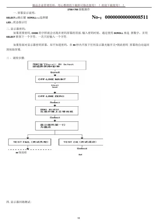
精品企业管理资料,用心整理的下载即可修改使用! !欢迎下载使用! !2700/1700面板操作二.显示器密码:如果需要密码,CODE 的字样就会出现在密码屏幕的顶部.输入密码时候,通过使用SCROLL 来选 择数字,并用SELECT 移到下一个字符,一次只好输入一个字符.如果你面对显示器密码屏幕,却不知道密码,在60秒内不按下任何显示器光敏开关•则此密码 屏幕将自动退回到初始屏幕. 三・ 调零步骤:四.显示器回路测试:一.屏幕显示说明:SELECT —确认键 SCROLL-—选择键 LED …状态指示灯No-:00000000000008511S^lo-ct IScrollnr 隊故昭ExitSelectScrollOFF-LINE SIMSelectScrollSoloct Soloct Select Scroll4 mA 12 mA 20 mA 1 KHz10 KHzON OFF____________ I IScroll Scroll• •匕•读取接受设备的 :输岀数?□ ST1回路测试成功:按按钮.停止仿臭:Scroll-Exit五・显示器查看报警:LED指示灯状态及报警査看状态指示灯的状态报警优先级⑴如果报警菜单被禁止,则无法确认报警。
在这种情况下,状态指示将不再闪烁.报警按照报警队列中的优先级排列,要查看队列中某指定报警:1. 同时按下Scroll和Select按钮」当屏幕上出现“SEE ALAR『时,松开按钮。
参阅图7T。
2. 按Select按钮。
3. 如果屏幕上交替出现“ACK ALL”时,则WoII按钮。
4. 如果屏幕上出现“NO ALARM” ,则到第6步,5. 按Scroll按钮查看队列中的毎个报警。
要了解显示器显示的报警代码的含义,请参阅第10.11章节。
6. 按Scroll按钮直到屏暮上出现“EXIT”。
7. 按Select按钮。
六.管理鬆积量和库存量:启动/停止所有累积值和库存置⑵进行滚动翻屏克到特定累积值出现复位SELECT| 如臬有需求.输入密码七:测量单位设置:SELECT+SCROLL 按 4------- ► SEE ALARM --------------------- ► [SCROLL]CO ---------------- ► [SELECT] MASS ^SELECTJ复位特定累积值⑴滚动翻屏直到特定累积值出现ISELECTOFFLINE MAINTAIN► [SELECT] > [SCROLL]如果有需求.输入密码SELECTSELECT SELECT精品企业管理资料,用心整理的下载即可修改使用! !欢迎下载使用! !按 SCROLL 直到出现 EXIT ------------------- ► [SELECT] 体积单位和密度单位设置和上述步骤相同八量程设置(LRV URV)[SELECT+SCROLL]按 4^► SEE ALARM —--------- ► [SCROLL] ----------------- ►OFFLINE MAINT — ----------- ► [SELECT]---- ►继续按SCROLL 直到出现 MAO1.MFLOW >------------- L ECT]fSRC MAO1 ■----------- C MAO1 ------------------- L][SELECT]> [SELECT]输入最EXITk按 SELECT 退出.其他量程设置和上述步骤相同・NOTE: SELECT+SCROLL 表示两个键同时按下可以按SCROLL 选择你要的单位 选定后按SELECT4 M ——输入最小量程----------------------------------►[SCROLL+SE«€TJ—►4MAO1大量程•[SCROLL][SELECT+SCRGU420> [SCROLL]号:202004061636。
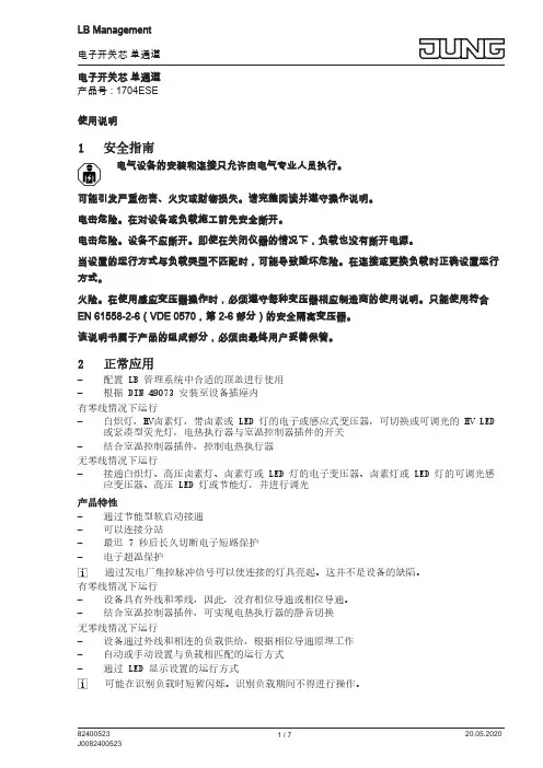
电子开关芯 单通道产品号 : 1704ESE使用说明1安全指南电气设备的安装和连接只允许由电气专业人员执行。
可能引发严重伤害、火灾或财物损失。
请完整阅读并遵守操作说明。
电击危险。
在对设备或负载施工前先安全断开。
电击危险。
设备不应断开。
即使在关闭仪器的情况下,负载也没有断开电源。
当设置的运行方式与负载类型不匹配时,可能导致毁坏危险。
在连接或更换负载时正确设置运行方式。
火险。
在使用感应变压器操作时,必须遵守每种变压器相应制造商的使用说明。
只能使用符合EN 61558-2-6(VDE 0570,第 2-6 部分)的安全隔离变压器。
该说明书属于产品的组成部分,必须由最终用户妥善保管。
2正常应用–配置 LB 管理系统中合适的顶盖进行使用–根据 DIN 49073 安装至设备插座内有零线情况下运行–白炽灯,HV卤素灯,带卤素或 LED 灯的电子或感应式变压器,可切换或可调光的 HV LED 或紧凑型荧光灯,电热执行器与室温控制器插件的开关–结合室温控制器插件,控制电热执行器无零线情况下运行–接通白炽灯、高压卤素灯、卤素灯或 LED 灯的电子变压器、卤素灯或 LED 灯的可调光感应变压器、高压 LED 灯或节能灯,并进行调光产品特性–通过节能型软启动接通–可以连接分站–最迟 7 秒后长久切断电子短路保护–电子超温保护通过发电厂集控脉冲信号可以使连接的灯具亮起。
这并不是设备的缺陷。
有零线情况下运行–设备具有外线和零线,因此,没有相位导通或相位导通。
–结合室温控制器插件,可实现电热执行器的静音切换无零线情况下运行–设备通过外线和相连的负载供给,根据相位导通原理工作–自动或手动设置与负载相匹配的运行方式–通过 LED 显示设置的运行方式可能在识别负载时短暂闪烁。
识别负载期间不得进行操作。
3操作本说明书介绍了按键端的使用。
相应套筒的说明书中介绍其它套筒的操作。
通过带电键套或按键的双线分机进行操作基本符合主机上的操作。
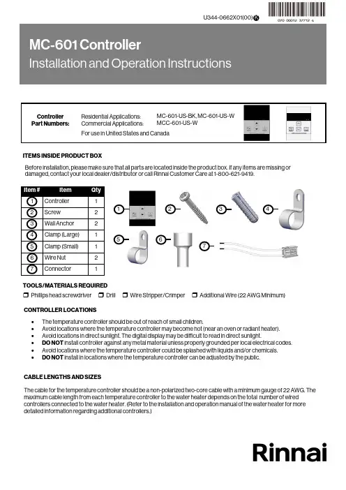
CONTROLLER LOCATIONS ∙ The temperature controller should be out of reach of small children.∙ Avoid locations where the temperature controller may become hot (near an oven or radiant heater). ∙ Avoid locations in direct sunlight. The digital display may be difficult to read in direct sunlight.∙ DO NOT install controller against any metal material unless properly grounded per local electrical codes. ∙ Avoid locations where the temperature controller could be splashed with liquids and/or chemicals. ∙DO NOT install in locations where the temperature controller can be adjusted by the public.CABLE LENGTHS AND SIZESThe cable for the temperature controller should be a non-polarized two-core cable with a minimum gauge of 22 AWG. The maximum cable length from each temperature controller to the water heater depends on the total number of wired controllers connected to the water heater. (Refer to the installation and operation manual of the water heater for moredetailed information regarding additional controllers.)Before installation, please make sure that all parts are located inside the product box. If any items are missing or damaged, contact your local dealer/distributor or call Rinnai Customer Care at 1-800-621-9419.123ITEMS INSIDE PRODUCT BOXTOOLS/MATERIALS REQUIRED456❒ Phillips head screwdriver ❒ Drill ❒ Wire Stripper/Crimper ❒ Additional Wire (22 AWG Minimum)71.Make 3 holes in the wall as shown below. (Reference template on last page.)2. Remove the face plate from the temperature controller using a screwdriver.When performing the steps in this section, you must follow the wiring guidelines established by the National Disconnect power to the water heater. Do not attempt to connect the temperature controller(s) with the power on.WARNING3. After disconnecting power to the water heater, connect the field-supplied wire to the stripped wire ends of the con-troller . Follow the wiring guidelines established by the National Electrical Code (NEC).4. Using the provided screws and wall anchors, mount the controller to the wall.5. Remove the protective film from the controller.Number of Controllers Maximum Cable Length for Each Controller toWater Heater1 328 ft. (100 m)2 164 ft. (50 m)3 or 465 ft. (20 m)Controllers wired in seriesControllers wired in parallelControllers canonly be wired in parallel; theycannot be wired inseries.FilmCover Plates3.31 i n . (84m m )1.65 i n . (42m m )1.Remove the front panel of the water heater.2. Locate the terminals for control in the water heater.3. Thread the cable through the base of the water heater4. Connect controller wires to the terminals for control.For additional information regarding installation and/or operation of the temperature controller, please refer to the Installation and Operation Manual of the water heater. 1.If the water heater is off, press the “On/Off” button to turn on.2. The “Priority” button enables a controller if multiple controllers are being used. If the “Priority” light is off, then press the“Priority” button on the temperature controller. The green “Priority” light will glow indicating that this controller iscontrolling the temperature and that the water heater is ready to supply hot water. The priority can only be changed while no hot water is running. 3. Press the (Up) or (Down) buttons to obtain the desired temperature setting. All hot water sources are able toprovide water at this temperature setting until it is changed again at this or another temperature controller. 4. To operate the water heater, open any hot water fixture. The water heater will then activate and the water heater “In Use”indicator will illuminate on the controller show that the water heater is providing hot water. For further information on controller operation, refer to the installation and operation manual of the water heater.Enables controller when multiplecontrollers are usedDisplayDecreases hot water temperatureIncreases hot water temperatureTurns the water heater on or off“In Use” IndicatorInstalling Four Controllers 1.If 4 MC-601’s are installed, press the “Priority ” and “On/Off ” buttons on the fourth controller at the same time until a beep sounds. (See above)2. Check that the displays on all four controllers are lit and displaying the temperature setting when switched on. If any ofthe controllers displays two dashes then repeat step 1. Note: If a controller is replaced, repeat these steps for the replacement controller.In applications where a Rinnai Control-R™ module is installed in place of a 4th controller and there is: ∙ Option 1 in Rinnai Control-R™ mobile app - “No Recirculation” - Perform Step 1 above.∙ Option 2 in Rinnai Control-R™ mobile app - “Recirculation” - Step 1 above is not necessary.HOTBURNSecuring Screw Securing Screw Wiring Hole Overall Controller Dimension: ∙ W: 3.54 in. ∙ H: 4.72 in. ∙D: 0.70 in.Ø.20Ø.50Ø.20100000570(02)9/2022。
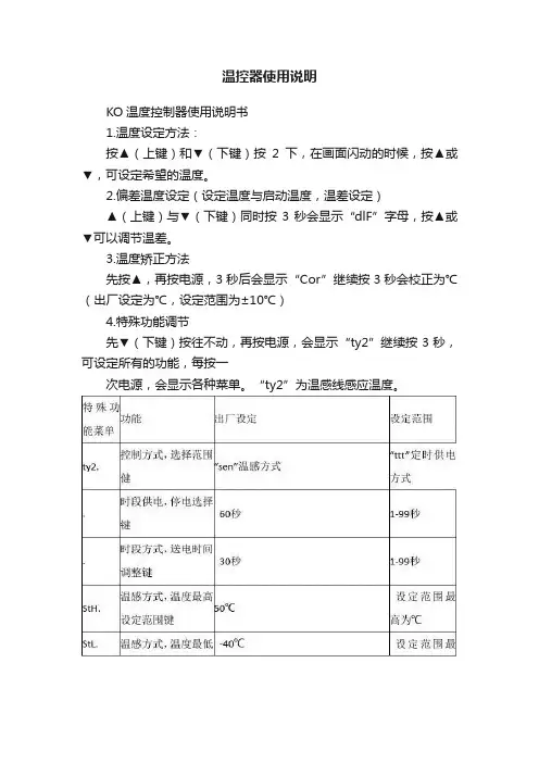
温控器使用说明KO温度控制器使用说明书1.温度设定方法:按▲(上键)和▼(下键)按2下,在画面闪动的时候,按▲或▼,可设定希望的温度。
2.偏差温度设定(设定温度与启动温度,温差设定)▲(上键)与▼(下键)同时按3秒会显示“dlF”字母,按▲或▼可以调节温差。
3.温度矫正方法先按▲,再按电源,3秒后会显示“Cor”继续按3秒会校正为℃(出厂设定为℃,设定范围为±10℃)4.特殊功能调节先▼(下键)按往不动,再按电源,会显示“ty2”继续按3秒,可设定所有的功能,每按一次电源,会显示各种菜单。
“ty2”为温感线感应温度。
5.时段供电温度调节方式按▲(上键),会显示“stp”继续按3秒,会显示1-5时段显示,出厂1档,设定范围0-5挡。
以下表格为各档送电和停电的时间表。
*档位越高温度越高,停止和供电方式反复工作*1档以上开始时自动供电。
6.定时关机设定方法▼(下键)按住3秒钟,显示“t_t”继续按3秒,在“too”状态,可设定定时关机功能,设定时间范围0-99个小时。
设定时间内正常工作,到了时间自动关机(出厂设定为0时)如显示“to9”9个小时就会自动关机,设定关机时间,会显示剩下多少时间,剩余时间显示“t11”就是剩11小时,“”就剩余8个小时50分钟。
定时,时间的变动,关机重启的话变成“0”。
*故障显示:—温感探头出现问题,它显示3秒后,自动转换成定时供电功能,温感探头恢复正常工作的话,重新转换到温度感应工作状态。
—记忆功能出现问题,停止输入电能,掐断电源,重新投入使用,要检查各功能是不是出厂状态。
OUT 输出(负载),IN 输入(220V)。
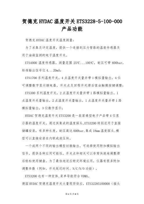
贺德克HYDAC温度开关ETS3228-5-100-000产品功能贺德克HYDAC温度开关温度测量:为了采集及评定温度,提供一个连接到压力管路的温度传感器及用于油箱监测的电子温度开关。
ETS4000温度传感器,测量范围25℃...100℃,耐压可带600bar,标准输出信号位4...20mA;ETS1700系列温度开关,4点温度开关量并带1模拟量输出,4位可调整数字显示继电器,开关点及回程开关滞后值由触摸按键调整; ETS300系列温度开关,2点温度开关量并带1路模拟量输出,1点温度开关量输出,2点温度开关量输出,1点温度开关量并带1路模拟量输出,3位数字显示;HYDAC贺德克温度开关ETS3200是一款紧凑型电子产品带4位显示器的温度开关。
通过其集成的温度探头,ETS3200特别适用于直接储罐安装,有多种长度。
耐压高达600bar,集成18mm温度探头,模型可以直接安装在内联或液压块。
一个或两个不同的输出模型切换输出,可选择使用附加模拟输出信号,提供各种应用可能性。
开关点和相关可以非常快速地调整滞后轻松使用键盘。
为了最佳地适应特定环境应用,仪器有很多附加调整参数(例如。
开关延迟时间、N/C/N/O功能)。
ETS3200也有一种变体,菜单导航符合VDMA。
德国HYDAC贺德克温度开关大量现货供应,ETS32285100000(插头ZBE08 5芯)现货图参考:德国HYDAC贺德克温度开关大量现货供应;德国HYDAC贺德克电子产品:EDS300系列、EDS3000系列、EDS210系列、EDS510系列、EDS601系列、EDS1700系列、HDA3800系列、HDA3840系列、HDA4400系列、HDA4500系列、HDA4700、HDA4755系列、ETS300系列等。
贺德克HYDAC温度开关ETS386系列产品功能正品保障上海现货HYDAC贺德克温度开关;HYDAC贺德克机组可以调节太阳能设备的碗状槽,或者操作电厂中的阀门和配件。
Operating Instructions Temperaturregler Temperature controller1094….1097 U-500 1094….1097 UTA-500 1095 UF-5001795 …-500Operating InstructionsTemperaturregler1Safety (3)2Intended use (3)3Environment (3)4Operation (4)5Technical data (5)6Setup and function (6)6.1Features of function and equipment (6)6.2Possible combinations (7)7Installation and electrical connection (8)7.1Requirements for the electrician (8)7.2Mounting (8)7.3Electrical connection (10)8Commissioning (11)8.1Calibrating the display of the actual temperature value (applies only to UTA devices) (11)8.2Offset function (scale correction) (11)1 SafetyWarningElectric voltage!Risk of death and fire due to electrical voltage of 230 V.– Work on the 230V supply system may only be performed by authorised electricians!– Disconnect the mains power supply prior to installation and/or disassembly!2 Intended useThe device is to be used exclusively with the components that are supplied and licensed as described in chapter "Setup and function".3 EnvironmentConsider the protection of the environment!Used electric and electronic devices must not be disposed of with domestic waste.– The device contains valuable raw materials which can be recycled. Therefore, dispose of the device at the appropriate collecting depot.All packaging materials and devices bear the markings and test seals for proper disposal. Always dispose of the packaging material and electric devices and their components via the authorized collecting depots and disposal companies.The products meet the legal requirements, in particular the laws governing electronic and electrical devices and the REACH ordinance.(EU Directive 2002/96/EC WEEE and 2002/95/EC RoHS)(EU REACH ordinance and law for the implementation of the ordinance (EC) No.1907/2006)4 OperationFig. 1: Cover5 Technical data GeneralNominal voltage 230 V AC ± 10%, 50/60 Hz24 V AC ± 10%, 50 Hz 1094, 1095, 1095 UF, 1097 1096Switching capacity 10 (4) A, 230 V AC16 A, 230 V AC1 (1) A, 24 V AC5 (2) A, 230 V AC 1094, 1095 1095 U 1096 1097Connection 1.5 mm² … 2.5 mm²2 x 2.5 mm² – 1 x 4 mm² 1094, 1095, 1095, 1097 1095 UFTemperature adjustment range 1 … 6 (5 … 30°C)1 … 6 (10 … 50°C) 1094, 1095, 1095, 1097 1095 UFTemperature reduction 4 KSwitching temperature difference ±0.5 K Protection type IP 20, EN (60529) Temperature sensor 1095 UF NTC 10 kΩ / 25°C Maximum cable length 1095 UF 4 mOperating temperature range 0 ...30 °C6 Setup and functionThe temperature controller is used to control the temperature in closed rooms.6.1 Features of function and equipmentArticle no. Features / Function1094 … •Opens when the set temperature is reached.•With separate connection for time-controlled reduction of nighttime temperature (4K).•Servo valves of "closed when de-energized“ design are required for the controller.1095 … •Opens when the set temperature is reached.•With normally open contact (not applicable for 1095 UF)•With separate connection for time-controlled reduction of nighttime temperature (4K).•With installed sliding switch and control lamp for nighttime temperature reduction (4 K).•Servo valves of "closed when de-energized“ design are required for the controller.… UF •With normally closed contact•With remote sensor (external temperature sensor for mounting in the floor) and thermal feedback.•For electric underfloor heating•Opening of the relay contact, when the set temperature is reached.1096 … •Opens when the set temperature is reached.•With separate connection for time-controlled reduction of nighttime temperature (4K).•With installed sliding switch and control lamp for nighttime temperature reduction (4 K).•Servo valves of "closed when de-energized“ design are required for the controller.1097 … •With switchover contact (heating / cooling)•Servo valves of "closed when de-energized“ design are required for the controller.… UTA •With display of actual temperature- Temperature display in steps of 0.5°C•Display accuracy: ±0,5°C for load currents of ≤2 A– Display accuracy: ±1,5°C for load currents of >2 A•Automatic controller calibration6.2Possible combinations1094 U 1097 U1094 UTA 1097 UTA1794-…X1794-…X1095 U / UF 1096 U1095 UTA1096 UTA1795-…X1795-…X7 Installation and electrical connectionWarningElectric voltage!Risk of death due to electrical voltage of 230 V during short-circuit in the low-voltage line.– Low-voltage and 230 V lines must not be installed together in a flush-mounted socket!7.1 Requirements for the electricianWarningElectric voltage!Install the device only if you have the necessary electrical engineering knowledge and experience.•Incorrect installation endangers your life and that of the user of the electrical system.•Incorrect installation can cause serious damage to property, e.g. due to fire.The minimum necessary expert knowledge and requirements for the installation are as follows:•Apply the "five safety rules" (DIN VDE 0105, EN 50110):1. Disconnect from power;2. Secure against being re-connected;3. Ensure there is no voltage;4. Connect to earth and short-circuit;5. Cover or barricade adjacent live parts.•Use suitable personal protective clothing.•Use only suitable tools and measuring devices.•Check the supply network type (TN system, IT system, TT system) to secure the following power supply conditions (classic connection to ground, protective earthing, necessaryadditional measures, etc.).7.2 MountingWarningElectric voltage!Risk of death and fire due to electrical voltage of 230 V.– Work on the 230V supply system may only be performed by authorised electricians!– Disconnect the mains power supply prior to installation and/or disassembly!The flush-mounted insert must only be installed in flush-mounted wall boxes according to DIN 49073-1, Part 1, or suitable surface-mounted housings.The temperature controller is suitable for use in dry rooms only.- To attach the adjusting knob, turn the two arrows towards each other (basic position).- Attach the adjusting knob vertically, so that the position lug (1) engages in the recess of the drive plate(2).1094 … / 1095 … 1095 UF 1097 … 1096 U Fig. 5: Circuit diagramsOperating Instructions | 1473-1-8290 — 11 —guide values. To obtain a setting that is as accurate as possible, the adjusting knob can be offset in 4 stages by a total of ±6°C as follows. Compare illustration 4:1. Pull off the adjusting knob (3).2. Cut the position lug (1) on the bottom side of the adjusting knob off with a suitable tool.3. Re-attach the adjusting knob, which has been offset to the basic position with the desired correcting value.Operating InstructionsTemperaturregler1473-1-8290 | R e v . 01 | 17.12.2012A member of the ABB GroupBusch-Jaeger Elektro GmbH PO box58505 LüdenscheidFreisenbergstraße 2 58513 Lüdenscheid Germany ***************.comCentral sales service:Phone: +49 (0) 2351 956-1600 Fax: +49 (0) 2351 956-1700NoticeWe reserve the right to at all times make technical changes as well as changes to the contents of this document without prior notice. The detailed specifications agreed to at the time of ordering apply to all orders. ABB accepts no responsibility for possible errors or incompleteness in this document.We reserve all rights to this document and the topics and illustrations contained therein. The document and its contents, or extracts thereof, must not be reproduced, transmitted or reused by third parties without prior written consent by ABB.Copyright© 2012 Busch-Jaeger Elektro GmbH All rights reserved。
These instructions are for your personal safety. Always ensure that you have read and understood these instructions before using any of the Picote range of Tools. SAVE THESE INSTRUCTIONS FOR FUTURE REFERENCE.OPERATION & SAFETY MANUALDistributed by HammerHead Trenchless SAFETY INFORMATION & SYMBOLS3 GENERAL INFORMATION & TECHNICAL DATA 5 VOLTAGE & POWER SUPPLY6CE DECLARATION OF CONFORMITY 7 OPERATING INSTRUCTIONS 8 MAINTENANCE & SPARE PARTS 10 WARRANTY POLICY & PROCEDURE11To watch practical demonstration videos, or to download an electronic copy of these In-structions, please visit . Please note that videos are not intend-ed as a replacement or alternative to this operating and safety manual, but only as an additional learning tool.TABLE OF CONTENTSSAFETY INFORMATIONThis section contains important safety information. Failure to comply could result in serious injury or death.Safety SymbolsSafety symbols are used throughout this manual to draw attention to potential hazards.Personal Protective Equipment (PPE)Always use Personal Protective Equipment when using the Picote Heater, including suita-ble overalls / protective clothing & footwear and the following:Always wear suitable eye protection when using the Picote Heater to prevent dust from irritating your eyes.Always wear suitable ear protection when using the Picote Heater to prevent any hearing loss.Always wear suitable cut -resistant gloves when using the Picote Heater to prevent any hand injuries. Any open injuries or skin irritations should be covered at all times to avoid contact with sewage, chemicals or dust. Always wear a suitable respirator when using the Picote Heater to prevent any resin fumes from the curing coating being inhaled or consumed, which can cause occupational asthma or dermatitis as well as eye irritation.Before assembly, use, replacement of parts or maintenance, unplug the Picote Heater. Failure to comply may lead to serious injury including electric shock or injury from rotating parts!Danger risk of serious injury from rotating parts, follow instructions.Always rememberDanger risk of serious injury, follow instructions.GENERAL MACHINE SAFETY WARNINGSAFETY REQUIREMENTSAlways read all safety warnings and instructions. Failure to follow warnings and instructions may result in electric shock, fire and/or serious injury.1. Always wear eye protection, ear protection as well as cut -resistant gloves. Other personal protective equipment, such as dust mask and overalls should be worn when necessary. Dust produced when working can be dangerous to your health, inflammable or ex-plosive. Always wear appropriate protective equipment. Make sure the drain pipe has been opened and ventilated to stop any gases forming in the lateral drain where the work takes place.2. Always ensure that the machine is fully turned off and unplugged before inspection, maintenance, or installing any accessories to the machine. Always follow the instructions in the Picote Solutions manual.3. Before each use inspect the machine and hose carefully for any potential break or damage. Change damaged parts immediately.4. When in use, it is very important that the machine is stable and on an even surface at all times.5. Do not use the machine outdoors when raining or in otherwise wet conditions.6. If the working environment is extremely hot and humid, or badly polluted by conductive dust, use a GFCI -enabled power outlet to ensure the safety of the operator.7. Make sure that the job location is well ventilated before powering up the machine. The operator must wear a dust mask when using the Picote Heater. Notice that the machine blows the dust and fumes out from the pipes at any opening. Prepare the ventilation properly on these locations before powering up the Picote Heater.8. Ensure that the ventilation openings are kept clear when working in dusty conditions. If it should be-come necessary to clear dust, first unplug the machine.9. Only use this machine with the accessories and spare parts offered by the Picote Solutions. Accessories and spare parts should only be used in the manner intended and as described by the Picote Solutions. 10. Read the Picote Brush Coating ™ manual carefully before using the Picote Heater to speed up the curing process.This section contains important safety information. Failure to comply could result in serious injury or death .This section contains important safety information. Failure to comply could result in serious injury or death.TECHNICAL DATASize (mm/inches)Hoselength(m/ft)Drain Diameter(mm/inches)Max. AirVolume(m3/min)Output(W)PowerSourceWeight(kg/lbs)Max. AirCapacity(m/sec)IP Rating287x205x180 11”x8”x7”5 (16)DN50-DN300 (2”-12”) 2.201600ElectricMotor5.8 (12.8)75—10023INTENDED USEThis machine is intended for the following uses;1.Drying the pipes after water cleaning.2.Speeding up the curing process when using the Picote Brush Coating™ system. GENERAL INFORMATIONVOLTAGE & POWER SUPPLYEnsure that the supply voltage is correct. The voltage of the power source must match the value given on the nameplate of the machine within the tolerances of ±10 %. Machines with a 230V plate can be used in 220V mains and 110V machines in the 120V grid.The machine has been double sealed according to European standards. The power source has to be grounded.Power plugsFor safety purposes, use only grounded outlets. If the plug does not fit securely or match the outlet, do not force it —contact an electrician to determine required power supply. Never alter the plug in any way. Use the plug with an extension cord only if it can be fully inserted into the receptacle. Use the Picote Heater with a heavy duty extension cord only.If a power generator is used as power source, ensure that the power rating is sufficient.220-230V:EU Schuko 230V 16A. Power cable lead minimum thickness 1.5mm2 .110-125V: The Picote Heater is equipped with a 15 amp (125V) NEMA 5-15 plug. Power cable lead minimum thickness 2,5mm2 / 13 AWG. The must be supplied with sufficient power and pro per current rating. A minimum of 15 amps are needed to operate it safely andeffciently. When used with an extension cord, the cord must be a 3 prong, 15amp (125V). If power generator is used, minimum 3 kW required. Adapters may be necessary for generator connections. Contact your reseller or Picote technical support for more information.AUSTRALIA/UK: Picote Heaters in these regions have special plugs:Australia: CEE 16A 230V colour blue. Power cable minimum lead thickness 2.5mm2UK: UK Plug BSEN 60309 16A 110V colour yellow. Power cable lead minimumthickness 2,5mm2. Picote Heater requires a transformer to comply with the sitepower regulations and safe usage in UK.NOISE LEVEL & EMISSIONSThe typical A -weighted noise level determined according to EN60745:Sound pressure level (LpA): 78 dB (A)WEAR EAR PROTECTIONEmissions during actual use of the machine can differ from declared values depending on the ways that the machine is used. Safety measures to protect the operator should be determined by actual condi-tions, taking into account all aspects of the operating cycle.Due to continuing product development, the specifications herein are subject to change without notice. We Picote Solutions Oy Ltd as the responsible manufacturer, declare that the following Picote Solutions Oy Ltd machine:Picote Heateris of series production andConforms to the following EU Directive: 2006/42/ECAnd is manufactured in accordance with the following standards or standardised documents: EN60745The technical documentation is kept by our authorised representative in Europe who is:Picote Solutions Oy Ltd, Urakoitsijantie 806450 Porvoo, Finland1st February 2018CE DECLARATION OF CONFORMITYKatja Lindy -WilkinsonC.E.O.Picote Solutions Oy LtdUrakoitsijantie 8, 06450 Porvoo, FinlandThis section contains important safety information. Failure to comply could result in serious injury or loss of hearing.OPERATING INSTRUCTIONSBefore operation:• Before powering up, always make sure that all the openings are properly ventilated. • Ensure there is enough space for Picote Heater. Do not cover the air inlet.•The dust and fumes from the pipes will be blown out from any opening in pipe system. Prepare all these locations before powering up the Picote Heater.While in operation:•Always lay the machine down horizontally on the floor.STARTING & USING THE MACHINE1.Ventilate all the openings in pipe system properly before powering up the Picote Heater. Dust, fumes and gases can be dangerous to your health, inflammable or explosive.2. Place the hose inside the pipe. Secure the hose with hose clamps or nozzle piece.3.Inspect that the curing process has already begun before powering up the Picote Heater. The resin needs to be dust dry before the Picote Heater can be used which equals to 20 minutes curing. If the Picote Heater is powered before the curing has started, waves will be created to the coating layer.Tip! You can use outlet timer to make Picote Heater to begin the blowing process after 20 minutes and to blow up for pre -calculated time. In this way you can move on coating the next pipe line faster. 4.Plug the Picote Heater to the power source.5. Picote Heater speeds up the curing time of the coating resin 1h – 1.5h depending on the coating resin used.5.Let the machine blow up as long as needed. Normally at least 2h 30 min is normally needed for the coating layer to cure before a new layer is going to be added. The coating material needs to be touch dry before adding a new coating layer.6.If the next coat is applied after 24h, the original coat needs to be abraded with a Smart Cutter ™ first to make sure that the layers bond well.Note: Picote Heater air outlet temperature is limited to +55 o C (131 F). The machine has automatic thermal cut -out in both motor and heating element.This section contains important safety information. Failure to comply could result in serious injury.Please check Picote Mini & Maxi Coating Pump manualsand visit for moredetailed information.Guiding the Air into The PipeUse Hose Clamps to attach the hose to the Picote Heater and guide the air into the pipe. Secure thehose to the pipe with hose clamps, tape or nozzle piece.MAINTENANCE1. Before performing any maintenance always check that the machine is fully turned off and unplugged.2. Carefully inspect the hose to ensure that there are no signs of wear and tear. Replace when required.3. For safety and efficiency, always keep the machine and its air inlet clean.If there is s problem that you cannot resolve with this manual, please consult your Reseller or PicoteYou must use only the Picote Solutions accessories and attachments with the machine described in this operations manual. The use of other accessories or attachments couldpresent a risk of injury or death. The accessories or attachments should only be used in the proper and intended manner, and always follow Picote Solutions instructions.ACCESSORIES & SPARE PARTS1350000024Picote Heater 230v1350000024US Picote Heater 110v US 1350000024UK Picote Heater 110v UK 9990001099 Heater Spare Hose 5mFor information about product training and support contact Picote or your authorised Picote Reseller.TRAININGWARRANTY POLICY AND PROCEDURELimited Warranty:Picote warrants to the original End User that the Product purchased by such End User will operate in accordance with and substantially conform to their published specifications when shipped or otherwise delivered to the End User and for a period of one (1) year, except electric motors for which the warranty period shall be six (6) months, provided, however, that Picote does not warrant any claim or damage underthisWarranty if such claim or damage results from:1.Consumable parts or normal wear and tear resulting from use of the Products,2.Product overload or overheated motor,3.Regular periodic maintenance of Products,4.Misuse, neglect, or improper installation or maintenance of the Products, or use of Productsnot for their intended purpose,5.Products that have been altered, modified, repaired, opened or tampered with by anyoneother than Picote or an authorized Picote Service Centre, or unsuitable or unauthorized spareparts, accessories or third party products when using the Products or;6.the use of the Products not in compliance with their respective Documentation, user manuals,safety and maintenance instructions, and any usage restrictions contained therein, or7.accident, fire, power failure, power surge, or other hazard.Otherwise, the Products are sold AS IS. End User is responsible for using the Products withintheir specifications and instructions as contained in the Documentation.EXCEPT AS SPECIFIED IN THIS WARRANTY, ALL EXPRESS OR IMPLIED CONDITIONS, REPRESENTATIONS, AND WARRANTIES INCLUDING, WITHOUT LIMITATION, ANY IMPLIED WARRANTY OR CONDITION OF MERCHANTABILITY, FITNESS FOR A PARTICULAR PURPOSE, NONINFRINGEMENT, SATISFACTORY QUALITY OR ARISING FROM A COURSE OF DEALING, LAW, USAGE, OR TRADE PRACTICE, ARE HEREBY EXCLUDED TO THE EXTENT ALLOWED BY APPLICABLE LAW. TO THE EXTENT AN IMPLIED WARRANTY CANNOT BE EXCLUDED, SUCH WARRANTY IS LIMITED IN DURATION TO THE WARRANTY PERIOD. BECAUSE SOME STATES OR JURISDICTIONS DO NOT ALLOW LIMITATIONS ON HOW LONG AN IMPLIED WARRANTY LASTS, THE ABOVE LIMITATION MAY NOT APPLY. This disclaimer and exclusion shall apply even if the express warranty set forth above fails of its essential purpose.1112 Revision Date: 5 Feb. 2019Revision number: Rev. 1Author: Mikko LångvikAccepted: Dawn GreigPlease Contact:Your Reseller / Salesperson or Picote International OfficesFinland. United Kingdom. USA. Dawn Greig Global Business Development & Creative Director+44 7585116508************************Anthony DeCavitch Global Sales Director+1 219 440 1404************************Jake SaltzmanWorld Wide Technical Director +1 706 436 1892************************Richard Swan Head of Technical Client Services+44 (0)7827 223237***************************Technical Support Production & R&D Raudoittajantie 4 06450 Porvoo, Finland ***************************Distributed by HammerHead Trenchless。
贺德克HYDAC温度开关ETS386-2-150-000常规型号德国HYDAC温度开关正品库存现货:德国HYDAC温度传感器应用领域德国HYDAC温度传感器是最早开发,应用*的一类传感器。
温度传感器的*大大超过了其他的传感器。
从17世纪初人们开始利用温度进行测量。
在半导体技术的支持下,本世纪相继开发了半导体热电偶传感器、PN结温度传感器和集成温度传感器。
德国HYDAC贺德克温度开关大量现货供应,德国HYDAC温度开关正品库存现货;ETS32285100000(插头ZBE08 5芯)现货图参考:HYDAC贺德克温度开关ETS3200是一款紧凑型电子产品带4位显示器的温度开关。
通过其集成的温度探头,ETS3200特别适用于直接储罐安装,有多种长度。
耐压高达600bar,集成18mm温度探头,模型可以直接安装在内联或液压块。
一个或两个不同的输出模型切换输出,可选择使用附加模拟输出信号,提供各种应用可能性。
开关点和相关可以非常快速地调整滞后轻松使用键盘。
为了最佳地适应特定环境应用,仪器有很多附加调整参数(例如。
开关延迟时间、N/C/N/O功能)。
ETS3200也有一种变体,菜单导航符合VDMA。
德国HYDAC贺德克温度开关大量现货供应;德国HYDAC贺德克电子产品:EDS300系列、EDS3000系列、EDS210系列、EDS510系列、EDS601系列、EDS1700系列、HDA3800系列、HDA3840系列、HDA4400系列、HDA4500系列、HDA4700、HDA4755系列、ETS300系列等。
HYDAC温度开关ETS1701100000产品原理德国HYDAC温度传感器应用领域温度传感器是最早开发,应用*的一类传感器。
温度传感器的*大大超过了其他的传感器。
从17世纪初人们开始利用温度进行测量。
在半导体技术的支持下,本世纪相继开发了半导体热电偶传感器、PN结温度传感器和集成温度传感器。
两种不同材质的导体,如在某点互相连接在一起,对这个连接点加热,在它们不加热的部位就会出现电位差。
DPi1701Temperature & Process InputGraphic Display Panel Meterand Data LoggerLINE GRAPH CHARTING MODEMAIN SCREEN -INVERT MODEHORIZONTAL BAR GRAPHMODEe-mail:**************For latest product manuals: Shop online at®User’s GuideFor complete product manual:/manuals/manualpdf/M5021.pdfRoHS 2 CompliantFigure 1. View of DPi1701 Back Panel With USB & Wireless OptionsFigure 2. Power & Mechanical Relay Output ConnectionsFigure 3. Different Input Type ConnectionsL (+)POWERN (-)OUTPUT 1N ON CCOUTPUT 21(-)I N P U T 2(+)34512345678910678910–++–V+–I–EXC+OUT R S 2 3 2GND RX TX N ON CC+–ANTENNAUSB PORT1(-)I N P U T2(+)345678910THERMOCOUPLE CONNECTION1(-)I N P U T2345678910RTD (100 OHMS) CONNECTION3 WIRE 2 WIRE1(-)I N P U T 23(+)45678910PROCESS (VOLTS) CONNECTION+–0/10V V1(-)I N P U T 234(+)5678910PROCESS (CURRENT) CONNECTION+–0/20mA or 4/20mAI–+Figure 4. RS232 Connections Figure 5. Excitation Voltage & Analog Output ConnectionsFigure 6. Configuration Menu Flow Chart1I N P U T 2345678910RS232 CONNECTIONGND RX TXEXCITATION & ANALOG OUTPUTARE NOT AVAILABLERS232Figure 8. MAX/MIN Flow ChartFigure 9. Lock/Unlock Flow ChartSPECIFICATIONS SUMMARYGENERALThermocouple AccuracyType J, Type K, Type E:, Type T:0.5ºC (0.9ºF)Type R & S:1°C (1.8°F) or 0.5% of full scaleThermocouple RangeType J:-100 to 760ºC (-148 to 1400ºF)Type K:-100 to 1260ºC (-148 to 2300ºF)Type E:-200 to 849°C (-328 to 1560°F)Type T:-200 to 400ºC (-328 to 752ºF)Type R & S:100 to 1760ºC (212 to 3200ºF)Thermocouple Warm up Period:45 minutesThermocouple Zero Drift: 0.06°C/°COpen Thermocouple Detection:Up scaleThermocouple Lead Resistance:100 ohms max.RTD:100 ohms Platinum, 2 or 3 wire, 0.00385curveRTD Accuracy:0.5ºC (0.9ºF)RTD Range:-200 to 850ºC (-328 to 1562ºF)Open RTD Detection:Up scaleProcess (Voltage or current)Input Accuracy:0.1% of RdgVoltage Input Range:0 to 10 VdcCurrent Input Range:0 to 20 mA and 4 to 20 mASampling Rate: 4 samples per secondGeneral Power:90/240 Vac +/-10%, 50-400 HzOperating Conditions:0 to 50ºC (32 to 122ºF), 90% RH non-condensingProtection:NEMA-1/Type 1 Front bezelDimensions:48H x 96W x 118mm D (1.89 x 3.78 x 4.65")WARRANTY/DISCLAIMEROMEGA ENGINEERING, INC. warrants this unit to be free of defects in materials and workmanship for a period of 61 months from date of purchase. OMEGA’s WARRANTY adds an additional one (1) month grace period to the normal five (5) year product warranty to cover handling and shipping time. This ensures that OMEGA’s customers receive maximum coverage on each product.If the unit malfunctions, it must be returned to the factory for evaluation. OMEGA’s Customer Service Department will issue an Authorized Return (AR) number immediately upon phone or written request. Upon examination by OMEGA, if the unit is found to be defective, it will be repaired or replaced at no charge. OMEGA’s WARRANTY does not apply to defects resulting from any action of the purchaser, including but not limited to mishandling, improper interfacing, operation outside of design limits, improper repair, or unauthorized modification. This WARRANTY is VOID if the unit shows evidence of having been tampered with or shows evidence of having been damaged as a result of excessive corrosion; or current, heat, moisture or vibration; improper specifica-tion; misapplication; misuse or other operating conditions outside of OMEGA’s control. Components in which wear is not war-ranted, include but are not limited to contact points, fuses, and triacs.OMEGA is pleased to offer suggestions on the use of its various products. However, OMEGA neither assumes respon-sibility for any omissions or errors nor assumes liability for any damages that result from the use of its products in accordance with information provided by OMEGA, either verbal or written. OMEGA warrants only that the parts manufactured by the company will be as specified and free of defects. OMEGA MAKES NO OTHER WARRANTIES OR REPRESENTATIONS OF ANY KIND WHATSOEV ER, EXPRESSED OR IMPLIED, EXCEPT THAT OF TITLE, AND ALL IMPLIED WARRANTIES INCLUDING ANY WARRANTY OF MERCHANTABILITY AND FITNESS FOR A PARTICULAR PURPOSE ARE HEREBY DISCLAIMED. LIMITATION OF LIABILITY: The remedies of purchaser set forth herein are exclusive, and the total liability of OMEGA with respect to this order, whether based on contract, warranty, negli-gence, indemnification, strict liability or otherwise, shall not exceed the purchase price of the component upon which liability is based. In no event shall OMEGA be liable for consequential, incidental or special damages.CONDITIONS: Equipment sold by OMEGA is not intended to be used, nor shall it be used: (1) as a “Basic Component” under 10 CFR 21 (NRC), used in or with any nuclear installation or activity; or (2) in medical applications or used on humans. Should any Product(s) be used in or with any nuclear installation or activity, medical application, used on humans, or misused in any way, OMEGA assumes no responsibility as set forth in our basic WARRANTY / DISCLAIMER language, and, additionally, purchaser will indemnify OMEGA and hold OMEGA harmless from any liability or damage whatsoever arising out of the use of the Product(s) insuch a manner.FOR WARRANTY RETURNS, please have the following infor-mation available BEFORE contacting OMEGA:1. P urchase Order number under which the product was PURCHASED,2. M odel and serial number of the product under warranty, and 3. R epair instructions and/or specific problems relative to the product.FOR NON-WARRANTY REPAIRS, consult OMEGA for current repair charges. Have the following information available BEFORE contacting OMEGA:1. Purchase Order number to cover the COST of the repair,2. Model and serial number of the product, and3. R epair instructions and/or specific problems relative to the product.OMEGA’s policy is to make running changes, not model changes, whenever an improvement is possible. This affords our customers the latest in technology and engineering. OMEGA is a registered trademark of OMEGA ENGINEERING, INC.RETURN REQUESTS / INQUIRIESDirect all warranty and repair requests/inquiries to the OMEGA Customer Service Department. BEFORE RETU RNING ANY PRODU CT(S) TO OMEGA, PU RCHASER MU ST OBTAIN AN AU THORIZED RETU RN (AR) NU MBER FROM OMEGA’S CU STOMER SERVICE DEPARTMENT (IN ORDER TO AVOID PROCESSING DELAYS). The assigned AR number should then be marked on the outside of the return package and on any correspondence.The purchaser is responsible for shipping charges, freight, insurance and proper packaging to prevent breakage in transit.Servicing North America:Omega Engineering, Inc., One Omega Drive, P.O. Box 4047S tamford, CT 06907-0047 USA Toll-Free: 1-800-826-6342 (USA & Canada only)Customer Service: 1-800-622-2378 (USA & Canada only) Engineering Service: 1-800-872-9436 (USA & Canada only) Tel: (203) 359-1660 Fax: (203) 359-7700 e-mail:**************For Other Locations Visit /worldwide***********************The information contained in this document is believed to be correct, but OMEGA accepts no liability for any errors it contains, and reserves the right to alter specifications without notice.WARNING: These products are not designed for use in, and should not be used for, human applications.。
ASCON spa via Falzarego 9/11 20021 博拉特 意大利(米兰) 电话: +39 02 333 371 传真: +39 02 350 4243 网址:http://www.ascon.it 邮箱:support@ascon.it温度控制器1/16德国标准 -48x48系列M1线用户手册•M.I.U.M1-4/04.07•编号J30-478-1AM1 IE通过ISO9001认证温度控制器1/16德国标准-48x48M1线对电气安全和电磁兼容的注释在安装控制器前,请先认真阅读下列指导。
第二类仪器,后面板安装。
控制器按照以下内容设计:电气设备规则根据欧洲共同体第93/68/EEC号指令修正的欧洲共同体第73/23/EEC号指令(设备、系统和安装)以及电气设备EN61010-1 :93 + A2:95中关于强制保护要求的规则。
电磁兼容规则根据欧洲共同体第n°92/31/EEC、93/68/EEC和98/13/EEC号指令修正的欧洲共同体第n089/336/EEC号指令,并遵守以下规则:射频排放规则:EN61000-6-3 : 2001 居住环境EN61000-6-4 : 2001 工业环境射频抗扰度规则:EN61000-6-2 : 2001 工业设备和系统让安装者了解其应遵守安全要求和EMC规则至关重要。
该设备不具备可供用户使用的部件,且需要使用专用设备并通过专业工程师来操作。
因此,用户不能轻易直接对设备进行维修。
为此,生产商可为客户提供技术援助和维修服务。
欲知详情,敬请联系最近的代理商。
所有关于安全和电磁兼容信息和警告都在注释侧面标明了标志。
目录1 安装 ..................................................................................................................... 第4页 2 电气连接 ............................................................................................................. 第8页 3 产品编码 ............................................................................................................. 第14页 4 操作 ..................................................................................................................... 第18页 5 自动调准 ............................................................................................................. 第28页 6 技术规范 . (29)(可选)指示专用主要通用输入单一动作资源 工作模式 单一动作 控制警告重新传输设置点 特殊功能通过自动选择模糊调整单次对焦自动调整单次对焦固有频率RS485通讯接口参数化监督1 安装只有合格人员才能进行安装在安装控制器前,请遵守该手册中的指令,特别是标有标志的安装防范,该标志与欧洲共同体关于电气保护和电磁兼容的指令有关。
170万吨/年渣油加氢装置操作法1 反应部分操作法R101温度的调节:影响因素:(1)F101的出口温度升高,床层温度上升。
(2)催化剂的活性提高,床层温度上升。
(3)E102、E103A/B的原料油出口温度提高,床层温度上升。
(4)循环氢流量减小,床层温度上升。
¥(5)原料含硫量变高,床层温度上升。
(6)原料含氮量变高,床层温度上升。
(7)原料中金属杂质含量变高,床层温度上升。
(8)原料变重,床层温度下降。
(9)循环氢纯度提高,床层温度上升。
(10)原料含水增加,床层温度波动。
调节方法:(1)通过调节F101的瓦斯量来控稳F101的出口温度。
((2)根据催化剂表现的活性和反应深度适当调整反应器入口温度。
(3)通过调节原料油换热器旁路阀TIC10801来控稳E102、E103A/B的管程出口温度。
(4)控稳循环氢流量,循环氢量不足时可提高C101的转速。
(5)联系调度和罐区,控好原料性质和混合比例,在切换原料时要认真分析比较原料油的性质,密切注视反应器床层温度的变化,保证换油过程中温度的平稳过渡。
(6)调节温度时要参照操作指导曲线。
(7)平稳两炉进料,保证两列不偏流。
二、三、四反反应温度的控制操作工业生产上调节二、三、四反温度的主要手段是调节各反应器入口冷氢量。
…影响因素:(1)各反入口温度升高,床层温度上升。
(2)反应器入口冷氢量减小,反应温度上升。
(3)反应深度增大,反应温度上升。
(4)原料油性质对反应温度的影响与R101相同。
(5)催化剂的活性增加,床层温度上升。
(6)循环氢纯度提高,反应温度上升。
调节方法:(1)通过调节各反的入口冷氢量来调节其入口温度和床层温度,保持各床层温升≯28℃。
(2)为了防止温度波动过大,每次调节温度的范围应在0.5℃左右。
(3)控制转化深度在设计范围内。
(4)原料油性质变化时,反应温度的调节方法与R101相同。
(5)根据催化剂表现的活性和反应深度适当调整反应器入口温度。