Wellflo操作手册
- 格式:ppt
- 大小:1.05 MB
- 文档页数:36
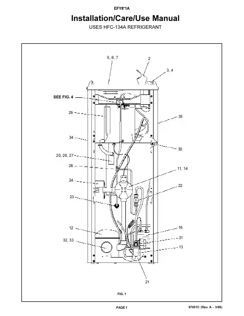
97051C (Rev. A - 3/98)Installation/Care/Use ManualUSES HFC-134A REFRIGERANTFIG. 13, 4SEE FIG. 43511, 1434232820, 26, 2722303113211625, 6, 724122932, 3397051C (Rev. A - 3/98)F IG . 2E = I N S U R E P R O P E R V E N T I L A T I O N B Y M A I N T A I N I N G 4" (102m m ) (M I N .) C L E A R A N C EF R O M C A B I N E T L O U V E R S T O W A L L .A S EG U R E U N A V E N T I L A C I ÓN A D E C U A D A M A N T E N I E N D O U N E S P A C I O E 4" (102m m ) (M ÍN .) D EH O L G U R A E N T R E L A R E JI L L A D E V E N T I L A C I ÓN D E L M U E B L E Y L A P A R E D A S S U R E Z -V O U S U N E B O N N E V E N T I L A T I O N E N G A R D A N T 4" (102m m ) (M I N .) E N T R E L E S ÉV E N T S D E L E N C E I N T E E T L E M U R .F = P O W E R C O R D 4 F E E T (1219m m ) L O N G C A B L E E L ÉC T R I C O D E 4 P I E (1219m m ), D E L A R G O C O R D O N D A L I M E N T A T I O N 4' (1219m m )G = W A L L S C R E W H O L E S A G UJ E R O S D E T O R N I L L O S D E P A R E D T R O U S D E V I S D U M U R H = 2 X 4 B L O CK I N G BL O Q U E O D E 2 X 4B L O C 2 X 4F I N I S H E D F L O O R P I S O A C A B A D O P L A N C H E R F I N IL E G E N D /L E Y E N D A /L ÉG E N D E A = R E C O M M E N D E D W A T E R S U P P L Y L O C A T I O N 3/8 O .D . U N P L A T E D C O P P E R T U B E C O N N E C T S T U B 1-1/2 I N . (38m m ) O U T F R O M W A L L S H U T O F F B Y O T H E R S S E R E C O M I E N D A U B I C A R E L T U B O C O R T O D E C O N E X I ÓN A L T U B O D E C O B R E S I N C H A P A R D E 3/8" D E D I ÁM . E X T . A 1-1/2"(38m m ) F U E R A D E L A L L A V E D E P A S O E N L A P A R E D C O L O C A D A P O R T E R C E R O S . E M P L A C E M E N T R E C O M M A N D É D 'A L I M E N T A T I O N E N E A U P A R T U B E E N C U I V R E N O N P L A Q U É D E 3/8 P O . (9,5 m m ) D .E .C O N N E C T A N T U N E T U Y A U T E R I E D E 1-1/2 P O . (38m m ) D E P U I S L E R O B I N E T D 'A R R ÊT F O U R N I P A R D 'A U T R E S .B = R E C O M M E N D E D L O C A T I O N F O R W A S T E O U T L E T 1-1/4 O .D . D R A I N U B I C A C I ÓN R E C O M E N D A D A P A R A E L D R E N A J E D E S A L I D A D E A G U A , D E 1¼ D E D I ÁM E T R O .E M P L A C E M E N T R E C O M M A N D É P O U R L E D R A I N D E D .E . 1-1/4" D E S O R T I E D E A U .C = 1-1/4 T R A P N O T F U R N I S H E D **P U R G A D O R D E 1¼ N O P R O P O R C I O N A D O **S I P H O N 1-1/4 N O N F O U R N I **D = E L E C T R I C A L O U T L E T L O C A T I O N U B I C A C I ÓN D E L A T O M A D E E L E C T R I C I D A D E M P L A C E M E N T D E L A P R I S E D E C O U R A N T97051C (Rev. A - 3/98)FIG. 3FIG. 4CONDENSER WATER VALVE ADJUSTMENTThe condenser water valve is factory preset for a condenser water outlet temperature of 95° to 105° F.If actual temperature varies greatly from this, readjust water flow rate at the valve using the following procedures.1.START UP COMPRESSORThis can be accomplished by depressing the cooler push button (See Fig. 1 - Item 3). Keep water running during the entire readjustment procedure.2. ADJUSTMENT CONDENSER WATER VALVEAdjust valve by rotating adjustment stem. Rotating stem clockwise will increase water flow. Counterclockwise rotation will decrease water flow. Increasing water flow will result in a lower condenser outlet temperature, while decreasing water flow will result in a higher outlet temperature. Proper adjustment is attained when condenser outlet temperature is 95° to 105° F.25101, 15, 1998STREAM HEIGHT ADJUSTMENT SCREWADJUST THIS SCREW TO ELIMINATE VALVE LEVER "FREE PLAY" ORCONTINUOUS FLOW FROM BUBBLERCORRECT STREAM HEIGHTPUSH BUTTON VALVE ADJUSTMENT97051C (Rev. A - 3/98)ELKAY MANUFACTURING COMPANY 2222 CAMDEN COURT OAK BROOK, ILPRINTED IN U.S.A.PARTS LIST 115VITEM NO.PART NO.DESCRIPTION123456789101112*1314151617181920212223242526272829303132333435NSNut-Regulator Retaining BubblerPush Button Stem Cap Push Button Drain Plug Strainer Plate ReceptorRegulator Lever Pivot BracketRegulator Retaining Bracket Cold Control CompressorValve - Wtr TempElectrical Box-Cold Control Regulator Holder Condenser Assy Evaporator Valve Assy Regulator Tailpipe Assy DrierCheck Valve StrainerElectrical Box-Power Connection Regulator Mounting Bracket Adaptor-Drain W/O Holes Nut 1-1/4 Slip Joint Tee - 1/4 x 1/4 x 1/4Vacuum Break Stem Bushing Elbow - 3/8Overload Relay Left Panel Right Panel Front Panel15005C 45314C 10150753155010154343164010263993164016027050864017140374259026860C 26861C 26862C 31513C 35790C 40136C 45340C 50986C 60141815155066327C 60159035155061314C 45689C 66202C 75494C 55996C 45347C 55880C 55913C 55885C 70682C 45346C 10145233187075561C 35797C 35803C 401536342830401536242830401507442830*REPLACE WITH SAME COMPRESSOR USED IN ORIGINAL ASSEMBLY.NOTE: All correspondence pertaining to ELKAY water coolers or orders for repair parts MUST include Model No. and Serial No. of cooler, name and part number of replacement part. 800-518-5388。
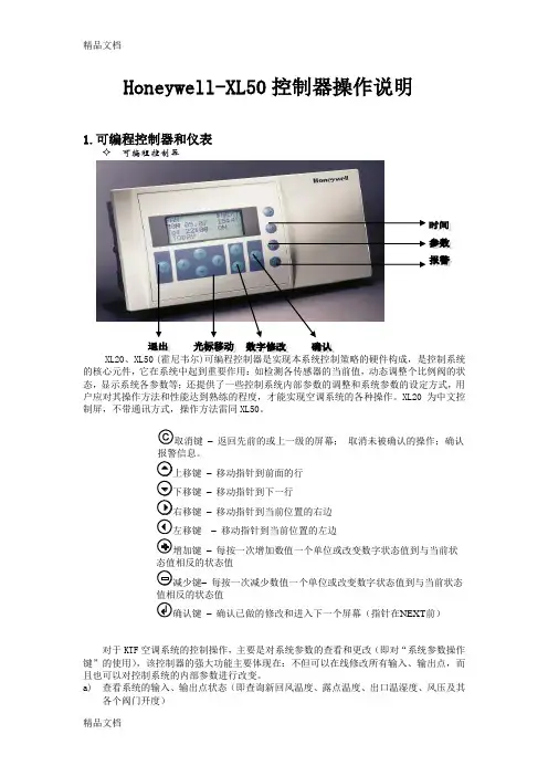
H o n e y w e l l-X L50控制器操作说明(总4页)-CAL-FENGHAI.-(YICAI)-Company One1-CAL-本页仅作为文档封面,使用请直接删除Honeywell-XL50控制器操作说明1.可编程控制器和仪表可编程控制器XL20、XL50 (霍尼韦尔)可编程控制器是实现本系统控制策略的硬件构成,是控制系统的核心元件,它在系统中起到重要作用:如检测各传感器的当前值,动态调整个比例阀的状态,显示系统各参数等;还提供了一些控制系统内部参数的调整和系统参数的设定方式,用户应对其操作方法和性能达到熟练的程度,才能实现空调系统的各种操作。
XL20为中文控制屏,不带通讯方式,操作方法雷同XL50。
取消键–返回先前的或上一级的屏幕;取消未被确认的操作;确认报警信息。
上移键–移动指针到前面的行下移键–移动指针到下一行右移键–移动指针到当前位置的右边左移键–移动指针到当前位置的左边增加键–每按一次增加数值一个单位或改变数字状态值到与当前状态值相反的状态值减少键–每按一次减少数值一个单位或改变数字状态值到与当前状态值相反的状态值确认键–确认已做的修改和进入下一个屏幕(指针在NEXT前)对于KTF空调系统的控制操作,主要是对系统参数的查看和更改(即对“系统参数操作键”的使用),该控制器的强大功能主要体现在:不但可以在线修改所有输入、输出点,而且也可以对控制系统的内部参数进行改变。
a) 查看系统的输入、输出点状态(即查询新回风温度、露点温度、出口温湿度、风压及其各个阀门开度)重要说明:对DDC 控制器的操作只能单键进行,严禁同时按压键位,以避免不必要的误操作,以免程序被初始化或删除。
按下系统“参数”操作键,屏幕出现“请输入你的密码”;密码输入才可以修改数据,比如压力等参数的设定等。
用户只是查看的话就可以直接进入。
移动“光标移动”向上键,使光标停留在“****”上,再按下“输入键”,通过使用“数据增/减键”和“输入键”逐个将4位密码输入,完毕后屏幕左下角出现‘更改change ’字符;光标移动到change 字符上可以修改进入DDC 修改数据的密码,默认为‘3333’,如更改了密码,用户须牢记更改后的密码,每次参数修改操作都需密码。
Honeywell-XL50控制器操作说明1.可编程控制器和仪表可编程控制器XL20、XL50 (的核心元件,它在系统中起到重要作用:如检测各传感器的当前值,动态调整个比例阀的状态,显示系统各参数等;还提供了一些控制系统内部参数的调整和系统参数的设定方式,用户应对其操作方法和性能达到熟练的程度,才能实现空调系统的各种操作。
XL20为中文控制屏,不带通讯方式,操作方法雷同XL50。
取消键–返回先前的或上一级的屏幕;取消未被确认的操作;确认报警信息。
上移键–移动指针到前面的行下移键–移动指针到下一行右移键–移动指针到当前位置的右边左移键–移动指针到当前位置的左边增加键–每按一次增加数值一个单位或改变数字状态值到与当前状态值相反的状态值减少键–每按一次减少数值一个单位或改变数字状态值到与当前状态值相反的状态值确认键–确认已做的修改和进入下一个屏幕(指针在NEXT前)对于KTF空调系统的控制操作,主要是对系统参数的查看和更改(即对“系统参数操作键”的使用),该控制器的强大功能主要体现在:不但可以在线修改所有输入、输出点,而且也可以对控制系统的内部参数进行改变。
a)查看系统的输入、输出点状态(即查询新回风温度、露点温度、出口温湿度、风压及其各个阀门开度)♦ 重要说明:对DDC 控制器的操作只能单键进行,严禁同时按压键位,以避免不必要的误操作,以免程序被初始化或删除。
♦ 按下系统“参数”操作键,屏幕出现“请输入你的密码”;密码输入才可以修改数据,比如压力等参数的设定等。
用户只是查看的话就可以直接进入。
♦ 移动“光标移动”向上键,使光标停留在“****”上,再按下“输入键”,通过使用“数据增/减键”和“输入键”逐个将4位密码输入,完毕后屏幕左下角出现‘更改change ’字符;光标移动到change 字符上可以修改进入DDC 修改数据的密码,默认为‘3333’,如更改了密码,用户须牢记更改后的密码,每次参数修改操作都需密码。

WHP 3000操作说明1.安全注意事项!2.规格技术参数3.操作说明4.外部传感器操作说明5.显示屏(4)错误指示6.其它“开机”项说明7.配件8.包装内含项目1.远程LED指示灯(通过RS232外部控制)2.高功率LED(大加热区高档600瓦/小加热区低档200瓦)3.外部传感器调节指示4.显示屏(3位数字,7项功能显示)5.“向上”按钮6.电源开关7.“向下”按钮8.调控情况的光指示9.“高功率”按钮(加热区高档600瓦/低档200瓦切换键)WHP3000快速参考一览表●向上按钮加值●向下按钮减值●切换大/小加热区功率高/低档●手动停止加热(关闭)●自动停止加热(自动关闭) 3秒或(分钟)“开机常规项”主要功能●待机功能ON/OFF●切换温度显示°C / °F●恢复出厂设置(FSE)尊敬的客户,感谢您购买了WELLER WHP3000红外预热板。
在制造过程中,我们按照严格的质量要求,确保设备一切功能的正常使用,以及为您带来最佳的焊接效果。
! 1. 安全注意事项!在安装使用设备之前,请务必仔细阅读以下操作说明和安全指示。
若违反安全指示操作,存在一定风险。
制造商将不会承担用于操作描述以外的其他用途或未经授权修改的赔偿责任。
根据基本安全要求,对应欧盟安全宣言,WELLER WHP3000红外预热板符合欧洲安全标准(89/336/ EEC,2006/95/EU)2.规格WHP3000红外预热板内装3块红外预热板,为线路板和电子元件提供预热。
红外预热板的波长为2-10μm,在此范围内可以快速、有效地为线路板预热。
温度的数字控制及显示确保了温度的准确性并支持其它特殊功能如“自动关闭”或待机温度。
数字化显示设定值及实际值。
有两个不同尺寸的加热区可供选择。
使用选配的外部传感器还可根据固定测量点调节温度。
集成的RS232接口使设备可以根据外部连接的WELLER WHA3000P/WHA3000V热风拆焊台进行控制。
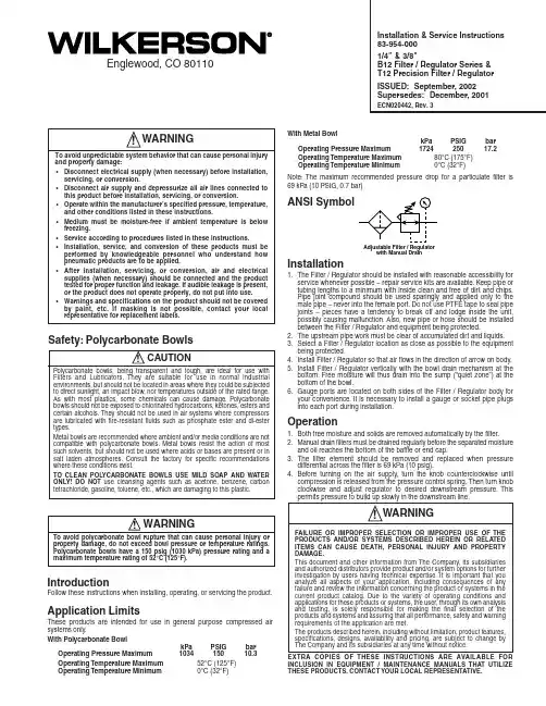
Adjustable Filter / Regulatorwith Manual DrainIntroductionFollow these instructions when installing, operating, or servicing the product.Application LimitsThese products are intended for use in general purpose compressed air systems only.With Polycarbonate BowlkPa PSIG bar Operating Pressure Maximum 103415010.3Operating Temperature Maximum 52°C (125°F)Operating Temperature Minimum0°C (32°F)Installation & Service Instructions 83-954-0001/4" & 3/8"B12 Filter / Regulator Series &T12 Precision Filter / Regulator ISSUED: September, 2002Supersedes: December, 2001ECN020442, Rev. 3!!WARNINGTo avoid unpredictable system behavior that can cause personal injury and property damage:•Disconnect electrical supply (when necessary) before installation,servicing, or conversion.•Disconnect air supply and depressurize all air lines connected to this product before installation, servicing, or conversion.•Operate within the manufacturer’s specified pressure, temperature,and other conditions listed in these instructions.•Medium must be moisture-free if ambient temperature is below freezing.•Service according to procedures listed in these instructions.•Installation, service, and conversion of these products must be performed by knowledgeable personnel who understand how pneumatic products are to be applied.•After installation, servicing, or conversion, air and electrical supplies (when necessary) should be connected and the product tested for proper function and leakage. If audible leakage is present,or the product does not operate properly, do not put into use.•Warnings and specifications on the product should not be covered by paint, etc. If masking is not possible, contact your local representative for replacement labels.WARNINGFAILURE OR IMPROPER SELECTION OR IMPROPER USE OF THE PRODUCTS AND/OR SYSTEMS DESCRIBED HEREIN OR RELATED ITEMS CAN CAUSE DEATH, PERSONAL INJURY AND PROPERTY DAMAGE.This document and other information from The Company, its subsidiaries and authorized distributors provide product and/or system options for further investigation by users having technical expertise. It is important that you analyze all aspects of your application, including consequences of any failure and review the information concerning the product or systems in the current product catalog. Due to the variety of operating conditions and applications for these products or systems, the user, through its own analysis and testing, is solely responsible for making the final selection of the products and systems and assuring that all performance, safety and warning requirements of the application are met.The products described herein, including without limitation, product features,specifications, designs, availability and pricing, are subject to change by The Company and its subsidiaries at any time without notice.EXTRA COPIES OF THESE INSTRUCTIONS ARE AVAILABLE FOR INCLUSION IN EQUIPMENT / MAINTENANCE MANUALS THAT UTILIZE THESE PRODUCTS. CONTACT YOUR LOCAL REPRESENTATIVE.Englewood, CO 80110Safety: Polycarbonate Bowls! CAUTIONPolycarbonate bowls, being transparent and tough, are ideal for use with Filters and Lubricators. They are suitable for use in normal industrial environments, but should not be located in areas where they could be subjected to direct sunlight, an impact blow, nor temperatures outside of the rated range.As with most plastics, some chemicals can cause damage. Polycarbonate bowls should not be exposed to chlorinated hydrocarbons, ketones, esters and certain alcohols. They should not be used in air systems where compressors are lubricated with fire-resistant fluids such as phosphate ester and di-ester types.Metal bowls are recommended where ambient and/or media conditions are not compatible with polycarbonate bowls. M etal bowls resist the action of most such solvents, but should not be used where acids or bases are present or in salt laden atmospheres. Consult the factory for specific recommendations where these conditions exist.TO CLEAN POL YCARBONATE BOWLS USE MILD SOAP AND WATER ONLY! DO NOT use cleansing agents such as acetone, benzene, carbon tetrachloride, gasoline, toluene, etc., which are damaging to this plastic.! WARNINGTo avoid polycarbonate bowl rupture that can cause personal injury or property damage, do not exceed bowl pressure or temperature ratings.Polycarbonate bowls have a 150 psig (1030 kPa) pressure rating and a maximum temperature rating of 52°C (125°F).With Metal BowlkPa PSIG bar Operating Pressure Maximum 172425017.2Operating Temperature Maximum 80°C (175°F)Operating Temperature Minimum0°C (32°F)Note: The maximum recommended pressure drop for a particulate filter is 69 kPa (10 PSIG, 0.7 bar)ANSI SymbolInstallation1.The Filter / Regulator should be installed with reasonable accessibility forservice whenever possible – repair service kits are available. Keep pipe or tubing lengths to a minimum with inside clean and free of dirt and chips.Pipe joint compound should be used sparingly and applied only to the male pipe – never into the female port. Do not use PTFE tape to seal pipe joints – pieces have a tendency to break off and lodge inside the unit,possibly causing malfunction. Also, new pipe or hose should be installed between the Filter / Regulator and equipment being protected.2.The upstream pipe work must be clear of accumulated dirt and liquids.3.Select a Filter / Regulator location as close as possible to the equipmentbeing protected.4.Install Filter / Regulator so that air flows in the direction of arrow on body.5.Install Filter / Regulator vertically with the bowl drain mechanism at thebottom. Free moisture will thus drain into the sump (“quiet zone”) at the bottom of the bowl.6.Gauge ports are located on both sides of the Filter / Regulator body foryour convenience. It is necessary to install a gauge or socket pipe plugs into each port during installation.Operation1.Both free moisture and solids are removed automatically by the filter.2.Manual drain filters must be drained regularly before the separated moistureand oil reaches the bottom of the baffle or end cap.3.The filter element should be removed and replaced when pressuredifferential across the filter is 69 kPa (10 psig).4.Before turning on the air supply, turn the knob counterclockwise untilcompression is released from the pressure control spring. Then turn knob clockwise and adjust regulator to desired downstream pressure. This permits pressure to build up slowly in the downstream line.B12 Filter / Regulator Series83-954-000* Element kits include body / bowl seal.† Grease in kits is silicone free.5.T o decrease regulated pressure settings, always reset from a pressurelower than the final setting required. Example, lowering the secondary pressure from 550 to 410 kPa (80 to 60 psig) is best accomplished by dropping the secondary pressure to 350 kPa (50 psig), then adjusting upward to 410 kPa (60 psig).6.When desired secondary pressure settings have been reached, push theknob down to lock this pressure setting.Bowl(See Warning)(Do Not Scratch Internal Surfaces)Clean with lint-free cloth.!ServiceCaution: Disconnect or shut off air supply and exhaust the primary and secondary pressures before servicing unit. Turning the adjusting knob counterclockwise does not vent downstream pressure on non-relieving regulators. Downstream pressure must be vented before servicing regulator.Note:Grease packets are supplied with kits for lubrication of seals.Use only mineral based grease or oils. Do not use synthetic oils such as esters. Do not use silicones.Note:After servicing unit, turn on air supply and adjust regulator tothe desired downstream pressure. Check unit for leaks. If leakage occurs, do not operate - conduct repairs and retest.Servicing Filter Element -1.Unscrew the bottom threaded collar and remove bowl.2.Unscrew the baffle and then remove element.3.Clean all internal parts and bowl before reassembling. See polycarbonatebowl cleaning section. IMPORT ANT: The Filter / Regulator will not operate properly if the deflector is not installed properly. The deflector must be installed between the filter holder and the filter body.4.Install new element.5.Attach baffle and finger tighten firmly.6.Replace bowl seal. Lightly lubricate new seal to assist with retaining it inposition.7.Install bowl into body and tighten collar; hand tight, plus 1/4 turn.Servicing Regulator -1.Disengage the adjusting knob by pulling upward. T urn adjusting knobcounterclockwise until the compression is released from the pressure control spring.2.Remove the bonnet and bowl assemblies by unscrewing the twothreaded collars.3.Remove diaphragm assembly from bonnet assembly.4.Remove filter stem, filter element, valve assembly, and valve returnspring.5.Clean and carefully inspect parts for wear or damage. If replacement isnecessary, use parts from service kits. Clean bowl. See polycarbonate bowl cleaning section.6.Lubricate o-ring and vee packing seals with grease found in service kits.7.Install valve return spring, valve assembly, (seat) insert and its o-rings,and filter stem. IM PORTANT: The Filter / Regulator will not operate properly if the defector is not installed properly. The deflector must be installed between the filter holder and filter body.8.Install filter element and firmly tighten baffle onto the filter holder.9.Install diaphragm assembly into bonnet assembly. Assemble bonnetassembly to body and tighten threaded collar hand tight, plus 1/4 turn.10.Install bowl into body and tighten collar; hand tight, plus 1/4 turn.Service Kits AvailableB12T12Description1/4" & 3/8"1/4" & 3/8"5 Micron Element*GRP-96-344GRP-96-34440 Micron Element*GRP-96-343GRP-96-343Bowl Guard Kit GRP-96-345GRP-96-345Non-Relieving Regulator Repair Kit †RRP-96-307—Relieving RegulatorRepair Kit †RRP-96-306RRP-96-305Sight Gauge Kit GRP-96-346GRP-96-346Metal Bowl Kits Manual Drain GRP-96-348GRP-96-348Piston Drain GRP-96-353GRP-96-353Sight Gauge &GRP-96-349GRP-96-349Manual Drain Sight Gauge &GRP-96-352GRP-96-352Piston DrainPolycarbonate Bowl KitsManual Drain GRP-96-347GRP-96-347Piston Drain GRP-96-351GRP-96-351Drain Kits Manual Drain GRP-96-340GRP-96-340Piston DrainGRP-96-354GRP-96-354。
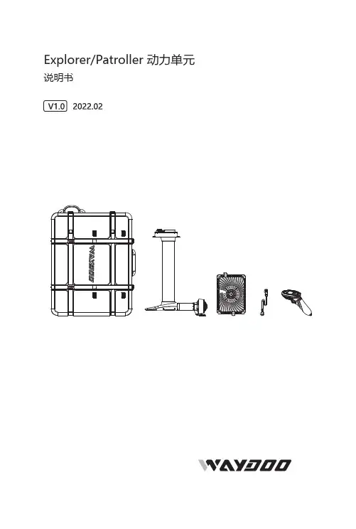
Explorer/Patroller 动力单元说明书目录免责声明Explorer/ Patroller 动力单元部件安装步骤便携箱如何使用维护保养安全指引故障解决方案免责声明使用前请仔细阅读本使用手册及相关警示,本产品为水上运动器材,使用本产品存在可能导致严重伤害甚至死亡的内在风险,使用本产品的用户须理解并接受使用本产品的固有风险,任何超出对本产品设计限制的滥用都可能导致产品损坏或人身伤害,作为产品开发的持续不懈努力,苇渡保留在不提前通知的情况下更改本产品的组件、规格或其他方面的权利,若了解最新资料 , 请浏览 : 。
包装清单充电器动力单元遥控器+遥控器+充电线充电器电源线工具包手腕带Waydoo Flyer ONE PlusWaydoo Flyer ONE Plus系列产品是Waydoo Flyer ONE的升级水翼板产品。
该系列包括智能电池、板体、动力单元、水翼等子产品。
这四个子产品需要组合以形成一套完整的水翼板产品。
用户可以根据自己的骑行需求自由选配。
除了 充电器、智能电池和水翼外,我们不建议用户将 Waydoo Flyer ONE 的子产品与 Flyer ONE Plus 的子产品混合搭配使用。
本手册是动力单元的说明书。
Explorer/Patroller 动力单元在本手册中统称为动力单元。
部件遥控器+采用人体工学设计,采用 LCD 显示界面。
显示内容分别为 智能电池和 遥控器+的电量,蓝牙连接和飞行速度。
它提供24档位供调节。
1. 从工具包中取出遥控器充电线。
2. 充电线一端插入 USB 充电器,将磁吸充电接头连接到 遥控器+, 充电接头自动吸附即可充电。
3.遥控器+正常充电时,顶部的灯会亮起。
充电时长为3小时。
6. 扳 机7. 指示灯遥控器+显示屏1. 遥控器+电量2. 速度3.智能电池电量4. 蓝牙连接5. 速度档位备注:1. 开启 遥控器+:按住 遥控器上的电源键5 秒钟,直到屏幕完全亮起。

Model 9221 Dual Satellite BrewerPRINTED IN UNITED STATES OF AMERICAp/n 76601 Rev. F ECN-13315 M671 070718 cps671 76601 Owners Manual 9221 Dual Satellite BrewerNOTE: For your protection, please note that equipment in this shipment was carefully inspected and packaged by skilled personnel before leaving the factory.Upon acceptance of this shipment, the transportation company assumes full responsibility for its safe delivery. IF SHIPMENT ARRIVES DAMAGED:1. VISIBLE LOSS OR DAMAGE: Be certain that any visible loss or damage is noted on the freight bill or express receipt, and that the note of loss or damage is signed by the delivery person.2. FILE CLAIM FOR DAMAGE IMMEDIATELY: Regardless of the extent of the damage.3. CONCEALED LOSS OR DAMAGE: if damage isunnoticed until the merchandise is unpacked, notify the transportation company or carrier immediately, and file “CONCEALED DAMAGE” claim with them. Thismust be done within fifteen (15) days from the date the delivery was made to you. Be sure to retain the container for inspection.Wells Bloomfield cannot assume liability for damage or loss incurred in transit. We will, however, at your request, supply you with the necessary documents to support your claim.1. Resetting of safety thermostats, circuit breakers, overload protectors, or fuse replacements unless warranted conditions are the cause.2. All problems due to operation at voltages other than specified on equipment nameplates; conversion to correct voltage must be the customer’s responsibility.3. All problems due to electrical connections not made in accordance with electrical code requirements and wiring diagrams supplied with the equipment.4. Replacement of items subject to normal wear, to include such items as knobs and light bulbs. Normal maintenance functions including adjustment of thermostats, microswitches,and replacement of fuses and indicating lights are not covered under warranty. 5. All problems due to inadequate water supply, such as fluctuating, or high or low water pressure. 6. All problems due to mineral/calcium deposits, or contamination from chlorides/chlorines. De-liming is considered a preventative maintenance function and is not covered by warranty.All electrical equipment manufactured by WELLS BLOOMFIELD, LLC is warranted against defects in materials and workmanship for a period of one year from the date of original installation or eighteen (18) months from the date of shipment from our factory, whichever comes first, and is for the benefit of the original purchaser, except that: a. airpots carry a 30 day parts warranty only. b. dispensers; i.e., tea and coffee carry a 90 days parts warranty only, excludes decanters. THE FOREGOING OBLIGATION IS EXPRESSLY GIVEN IN LIEU OF ANY OTHER WARRANTIES, EXPRESSED OR IMPLIED, INCLUDING ANY IMPLIED WARRANTY OF MERCHANTABILITY OR FITNESS FOR A PARTICULAR PURPOSE, WHICH ARE HEREBY EXCLUDED.WELLS BLOOMFIELD, LLC SHALL NOT BE LIABLE FOR INDIRECT, INCIDENTAL OR CONSEQUENTIAL DAMAGES OR LOSSES FROM ANY CAUSE WHATSOEVER.This warranty is void if it is determined that upon inspection byan Authorized Service Agency that the equipment has beenmodified, misused, misapplied, improperly installed, ordamaged in transit or by fire, flood or act of God.It also does not apply if the serial nameplate has been removed or unauthorized service personnel perform service. The prices charged by Bloomfield Industries for its products are based upon the limitations in this warranty. Seller’s obligation under this warranty is limited to the repair of defects without charge by a Bloomfield Authorized Service Agency or one of its sub-agencies. This service will be provided on customer’s premises for non-portable models. Portable models (a device with a cord and plug) must be taken or shipped to the closest Authorized Service Agency, transporta-tion charges prepaid, for services.In addition to restrictions contained in this warranty, specific limitations are shown below (Additional Warranty Exclusions).Bloomfield Industries Authorized Service Agencies are located in principal cities.This warranty is valid in the United States and void elsewhere. Please consult your classified telephone directory or your food service equipment dealer; or, for information and other details concerning warranty, write to:Service Parts Department Wells Bloomfield, LLC P.O. Box 280 Verdi, NV 89439 Phone: (888) 492-2782 Fax: (888) 492-27837. Full use, care and maintenance instructions are supplied with each machine. Those miscellaneous adjustments noted are customer responsibility. Proper attention will prolong the life of the machine. 8. Travel mileage is limited to sixty (60) miles from an authorized Service Agency or one of its sub-agencies. 9. All labor shall be performed during normal working hours. Overtime premium shall be charged to the customer. 10. All genuine Bloomfield replacement parts are warranted for ninety (90) days from date of purchase on non- warranted equipment. Any use of non-genuine Bloomfield parts completely voids any warranty .11. Installation, labor and job check-out are not considered warranty. 12. Charges incurred by delays, waiting time or operating restrictions that hinder the service technicians ability to perform services are not covered by warranty. This includes institutional and correctional facilities. xi10. Reinstall tank lid assembly into hot water tank. Make sure the lid gasket is properly in place, then reinstall the hold- down clamps.11. Remove spray disks and gaskets. Rinse both brew heads with clean water. Using a stiff brush, scrub spray disk to remove any lime or calcium build-up. Reinstall gaskets and spray disks.13. Reconnect brewer to electrical supply .14. Install the brew chamber without filter paper or grounds.15. Place an empty satellite under the brew chamber. Run at least five 1-1/2 gallon brew cycles and discard all water generated at the end of each cycle. Repeat for the other side.16. Rinse satellite with clean water. Reinstall one empty satellite under each brew chamber.Brewer is ready to use.NOTE: Normally, silicone hoses do not need to be delimed. Should deliming hoses become necessary, Bloomfield recommends replacing the hoses.13671 76601 O w n e r s M a n u a l 9221 D u a l S a t e l l i t e B r e w e r671 76601 O w n e r s M a n u a l 9221 D u a l S a t e l l i t e B r e w e r23671 76601 O w n e r s M a n u a l 9221 D u a l S a t e l l i t e B r e w e rPRINTED IN UNITED STATES OF AMERICA。
目 录WESLO 是 ICON IP, Inc. 的注册商标重要注意事项............................................................................................................................................................3用前说明...................................................................................................................................................................5组装..........................................................................................................................................................................6操作与调整..............................................................................................................................................................12如何折叠和移动跑步机............................................................................................................................................18故障检修.................................................................................................................................................................20锻炼指导.................................................................................................................................................................22零件清单.................................................................................................................................................................24分解图.....................................................................................................................................................................25售后服务..............................................................................................................................................................封底有限担保..............................................................................................................................................................封底1.产品所有人有责任确保所有跑步机使用者都充分了解所有的警告和注意事项。
Volvo Trucks.Driving ProgressInformación de servicioInformación de producto sobre camiones Volvo,para personal de servicios de emergenciaFL FEPrólogoLas descripciones y los procedimientos de servicio se basan en diseños y en estudios demétodos realizados hasta septiembre2012.Los productos son desarrollados continuamente.Para los vehículos y componentes fabricados luego de la fecha mencionada,pueden por lo tanto corresponder especificaciones y métodos de reparación distintos.Cuando se considere que ello pesa significativamente para el manual presente,se publicaráuna versión actualizada del mismo que incluya los cambios.En la próxima edición del manual estas modificaciones quedan actualizadas.En las instrucciones en donde hay incluido el número de operación en el rubro,tan solo se trata de una referencia al tarifario VST(Volvo Standard Times).Las instrucciones sin número de operación en el rubro son solamente una información general y no hacen referencia a VST.En esta información de servicio se utilizan los siguientes niveles en observación y advertencia. Nota:Indica un método,práctica o condición que debe ser seguido para que la función del vehículo o componente sea realizada en la forma apropiada.Precaución:Indica un procedimiento que no es seguro y que puede acarrear daños al producto.Advertencia:Indica un procedimiento que no es seguro y que puede acarrear heridas al personal o graves daños al producto.Peligro:Indica un procedimiento que no es seguro y que puede causar heridas graves al personal e incluso la muerte.Volvo Truck CorporationGöteborg,SwedenNúmero de pedido:89073870©2012Volvo Truck Corporation,Göteborg,SwedenInformación de productos-FE,FL Información de producto sobre servicios de emergencia de Volvo TrucksContenido•“Introducción”,página2•“Cabina”,página3•“Sistema eléctrico”,página4•“Habitáculo del conductor”,página7•“Ajuste del volante”,página7•“Sistema SCR”,página9IntroducciónT1008650 La finalidad de este documento es proporcionar informaciónsobre productos de tipo técnico,que pueda usarse para es-tablecer rutinas y métodos para actuaciones de salvamentoen accidentes de tráfico donde se haya visto involucrado uncamión Volvo.El presente documento se destina a los Equipos de salva-mento locales,responsables de actuaciones de salvamentoen el lugar del accidente.El documento contiene la siguienteinformación:•Cabina del conductor•Sistema eléctrico•Puesto de conducción y ajustes del volante•SRS/sistema de airbag•Sistema SCRCabinaLas cabinas antiguas están fabricadas en chapa de acero de materiales blandos unidos por soldadura.Por su lado,los modelos de cabina más modernos están fabricados en acero de alta resistencia.A continuación presentamos un dibujo esquemático de la es-tructura de cabina,donde las zonas de chapa de alta resis-tencia se han marcado de color gris claro y gris oscuro.Refuerzo decabinaC8063199Sistema eléctrico Recomendaciones generales:Hay dos tipos de interruptores para cortar la corriente eléc-trica del vehículo.Son el interruptor principal y el disyun-tor de ADR.Interruptor principal•El interruptor de suministro principal sólo funciona cuan-do el motor estádesconectado.NO corta la alimentación del tacógrafo,el sistema de cierre centralizado,la alarma Despuésde usarDisyuntor de ADR•En vehículos que transportan mercancías peligrosas de-be haber siempre un disyuntor de ADR.Cuando se usa este disyuntor se corta todo el sumi-nistro eléctrico independientemente de si el motor¡Advertencia!para desconectar Nota!Solamente la desconexión desde la batería o con el disyuntor de ADR corta TODO el suministro eléctrico.•Cuando se ha desconectado la alimentación de batería, se guarda energía en la unidad de mando de SRS duran-te unos segundos,tiempo suficiente para activar el air-bag o el tensor de cinturón de seguridad.Para asegurar que el sistema estádesenergizado,esperar unos3se-gundos después de desconectar la alimentación de labatería.•Antes de desconectar la corriente:¡Considerar la po-sible necesidad de abrir puertas o mover el asiento del conductor!(Ver:“Habitáculo del conductor”,página 7Si el asiento del conductor es ajustable eléctricamente,no seráposible ajustarlo después de cortar la electricidad porque el asiento no tiene mandos mecánicos.•La apariencia y la función varían entre diferentes inte-rruptores principales.Algunos modelos de camión care-cen de interruptor principal.¿Cómo se desconecta la corriente?•Desconectar el interruptor principal.No se desconec-tan todos los circuitos del camión;algunas partes especí-ficas del vehículo permanecen energizadas.No todas lascabinas tienen interruptor principal.•Interrumpir el circuito de batería soltando/cortando elcable de los bornes de batería.Ésta es la forma más se-gura de interrumpir la tensión.Se interrumpe toda la ten-sión,incluso del tacógrafo.Tener en cuenta que el vehículo sigue estando energiza-do si sólo se quita la llave de contacto.Con respecto aSRS,permanece energía almacenada en la unidad de man-do de SRS durante unos segundos después de cortarse elsuministro.Esta energía es suficiente para activar el airbag yel tensor de cinturón de seguridad durante hasta tres segun-dos después de cortar el suministro.La cifra indica la posición normal de la batería.1Caja de baterías de montaje lateral.Se puede montar en el lado izquierdo o derecho.2Caja de baterías de montaje posterior.T3072656Diferentes formas de cortar el suministro eléctrico:D.Interruptor principal telemandado.No existe en todos los vehículos.Pulsando el botón izquierdo dos veces dentro de cinco segundos,se desconecta el interruptor principal.Algunos circuitos permanecenenergizados.T301-7347C.Disyuntor de ADR.Sólo existe en vehículos que trans-portan mercancías peligrosas.Desconecta TODA lacorriente.C8063014B.Interruptor principal/interruptor de batería.Se encuentra en todos los vehículos.Algunos circuitos siguen excitados.A.Batería.Cuando se interrumpe el circuito de batería,empezar con el borne nega-tivo.Si es necesario cortar,hacerlo lo más cerca posible de la batería para reducir el riesgo de conexiones junto a los cables principales.Nota!¡Atención!No todos los componentes de la figura arri-ba están en todos los vehículos.Sistema de cierre centralizadoEl sistema de cierre centralizado se inmoviliza interrumpien-do el circuito de batería.En vehículos para transporte de mercancías peligrosas,el cierre centralizado también se in-moviliza desde el interruptor principal.Las puertas bloqueadas se pueden abrir desde el interior usando la empuñadura de apertura.Habitáculo del conductorDiseño del asientoExisten varios modelos de asiento para los diferentes mode-los de camión.El ajuste de posición de asiento vuelto atrás y adelante es en algunos casos mecánicos,pero los modelos más avanza-dos tienen ajuste eléctrico.Los modelos con ajuste mecánico se ajustan con una empu-ñadura situada debajo de la parte frontal del cojín de asiento,y los que tienen ajuste eléctrico se ajustan con un botón si-tuado en el lado izquierdo del asiento.Nota:los asientos con ajuste eléctrico no tienen sistema de ajuste mecánico.Para más información,ver:“Sistema eléctrico”,página 4Ajuste de asiento en sentidolongitudinalT8010409T8010449Ajuste con horquilla.Ajuste eléctrico.Ajuste del volanteHay un botón de operación neumática o una palanca mecá-nica en la columna de dirección.Cuando es necesario cortar o aserrar en el volante,la mane-ra más fácil es hacerlo en las zonas marcadas en blanco de acuerdo a la figura de abajo.El resto de las secciones están reforzadas.Perfil de refuerzo del volante y ajuste delvolanteT0013497T6009538Ajuste del volante.Cortar el volante.Sistema SCRRecomendaciones generales:•Cuando se para el motor,la solución de urea es bombea-da de vuelta al depósito de urea y se vacía la solución de urea del sistema SCR.Este proceso tarda unos dos minu-tos.Si se usa el interruptor de ADR para cortar la corrien-te antes de terminarse este proceso,el sistema puedeseguir estando presurizado y contener de solución deSi se usacuando•La urea es muy corrosiva y puede dañar conectores.Si la urea entra en contacto con conectores desenchufados, hay que cambiarlos de inmediato.No sirve de nada lim-piar porque la solución de urea se dispersa rápidamente en el cable,causando oxidación del metal.El derrameevaporaciónLas zonasen vehículosSistema SCREl sistema de urea es la parte del sistema de postratamientode los gases de escape que tienen algunos motores nuevospara cumplir con los requisitos de emisiones de Euro 4.Se inyecta una solución de urea en los gases de escape an-tes de que atraviesen el catalizador,para reducir las emisio-nes de óxidos de nitrógeno en los gases de escape.Los componentes principales del sistema SCR son:de-pósito de urea,unidad de bomba,unidad dosificadora y silenciador con catalizador incorporado.Sinopsis del sistema SCR y sus componentesprincipales:T20229851.Depósito de urea2.Unidad de bomba3.Unidad dosificadora4.SilenciadorSolución de ureaLa solución de urea,formada por agua destilada y un 32,5%de urea,es un líquido incoloro que puede tener un suaveolor a amoniaco.La solución de urea puede ser agresiva contra determinadosmateriales y se debe manipular con cuidado.La solución no es inflamable.A temperaturas altas la solución de urea se descompone enamoniaco y dióxido de carbono,y a temperaturas inferioresa –11°C la solución se puede congelar.La solución de urea es corrosiva a los metales,especialmen-te el cobre y el aluminio.Manipulación de la solución de urea:En caso de contacto con la piel:enjuague bien con agua tibia y quítese las prendas contaminadas.En caso de contacto con los ojos:enjuague bien con agua durante varios minutos y acuda a unmédico en caso necesario.En caso de inhalación:respire aire fresco y acuda a un médico en caso necesario. En caso de ingestión:beba agua89073870Spanish1.05Edición01 Volvo Truck Corporation。
附件2 WellFlo操作指南1引言WellFlo程序模块可用于垂直井、水平井、生产井、注入井进行气井建模分析、综合考虑石油天然气在地层、井筒、地面的规律,综合考虑不同产层、完井方式、气井管柱、生产条件下的气井建模和分析,同时气举模块可用于气举设计及气举生产建模、电潜泵模块可用于泵特性建模。
本用户手册介绍了WellFlo模块的基本窗口及操作,为用户应用和掌握该软件系统提供帮助。
2软件安装与启动2.1 WellFlo模块安装与启动2.1.1 WellFlo模块对系统要求WellFlo模块可运行于Windows NT或2000以上系统,对计算机的基本要求:1) 400MHz处理器2) 推荐256MB内存3) 10MB的WellFlo安装空间及足够的空间以备建立WellFlo模型需要2.1.2 WellFlo模块的安装首先退出所有正在使用的应用程序,然后打开WellFlo安装程序文件夹,启动安装程序,按照安装向导提示,即可完成软件安装。
2.1.3 WellFlo模块的启动WellFlo模块的启动有二种方式:1)、使用Windows命令菜单打开“开始”菜单,从中选择“程序”弹出列有程序名称的子菜单,单击其中“程序\EPS\Flosystem”下的“WellFlo”即可启动WellFlo。
2)、使用快捷方式启动按钮用户可创建一个WellFlo快捷方式置于桌面。
建立快捷方式的方法是:打开“开始”菜单,从中选择“程序”弹出列有程序名称的子菜单,复制其中“Flosystem”下的“WellFlo”粘帖在桌面上即可,需要运行WellFlo时,只需在桌面上双击该快捷方式按钮即可启动。
2.1.4 WellFlo模块的退出单击WellFlo应用程序窗口右上角的按钮或者单击“File”菜单,选择“Exit”命令,并单击即可退出WellFlo,也可以采用快捷键ALT+F4退出该程序。
3 WellFlo窗口及基本操作3.1 WellFlo窗口启动WellFlo应用程序,进入WellFlo主界面如下图3-1所示,主界面分为标题栏、命令菜单栏、工作区。