O-RING密封的选型与设计_1
- 格式:ppt
- 大小:1.93 MB
- 文档页数:14
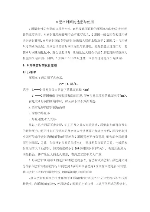
O型密封圈的技术数据及选择方法
o型密封圈是一种截面为圆形的橡胶圈,因其截面为o型,故称其为o型密封圈。
是液压与气压传动系统中使用最广泛的一种。
通常在台企、日企叫做oring。
o型密封圈是具有圆形截面的环行橡胶密封圈.主要用于机械部件在静态条件下防止液体和气体介质的泄露.在某些情况下.o型密封圈还能用做轴向往复运动和低速旋转运动的动态密封元件.根据不同的条件,可分别选择不同的材料与之相适应.
o型密封圈通常选用时要尽量选用大截面的o圈.在相同间隙的情况下.o型密封圈被挤入间隙的体积应当小于其被挤入的最大允许值。
对不同种类固定密封或动密封应用场合,o型密封圈为设计者提供了一种既有效又经济的密封元件。
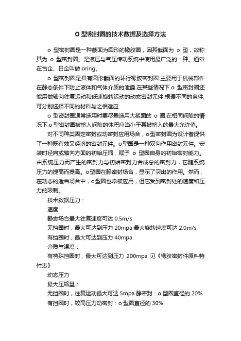
o型圈是一种双向作用密封元件。
安装时径向或轴向方面的初始压缩,赋予o型圈自身的初始密封能力。
由系统压力而产生的密封力与初始密封力合成总的密封力,它随系统压力的提高而提高。
o型圈在静密封场合,显示了突出的作用。
然而,在动态的适当场合中,o型圈也常被应用,但它受到密封处的速度和压力的限制。
技术数据压力:
速度:
静态场合最大往复速度可达0.5m/s
无挡圈时,最大可达到压力20mpa最大旋转速度可达2.0m/s
有挡圈时,最大可达到压力40mpa
介质与温度:
有特殊挡圈时,最大可达到压力200mpa见《橡胶密封件原料特性表》
动态压力
最大压缩量:
无挡圈时,往复运动最大可达5mpa静密封:o型圈直径的20% 有挡圈时,较高压力动密封:o型圈直径的30%。

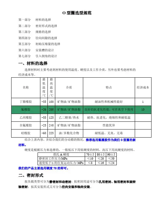
O型圈选型规范第一部分材料的选择第二部分密封形式的选择第三部分规格的选择第四部分径向间隙的选择第五部分初始压缩量的选择第六部分安装槽的设计第七部分引入倒角的设计一、材料的选择选择材料时主要考虑到材料的使用温度、硬度以及工作介质,另外也要考虑材料的经济成本等。
结合上表内容,并结合我们的分动箱的情况,推荐选用氟橡胶作为我们O型圈的新材料。
硬度是根据压力来选择的,一般低压下用低硬度的材料,高压下用高硬度的材料。
我们的产品主要选用硬度70的即可。
二、密封形式按负载类型可分为静密封和动密封;按密封用途可分为孔用密封、轴用密封和旋转轴密封;按其安装形式又可分为径向安装和轴向安装。
三、规格的选择O型圈的规格一般都是用内径和线径来表示的,而线径是有标准的。
大部分国家对O形密封圈都制定系列产品标准,其中美国标准(AS 568)、日本标准(JIS B 2401)、国际标准(ISO 3601/1)较为通用。
表1 O型圈标准一览表标准O型圈截面直径W美国标准 AS 568英国标准 BS 1516日本标准 JIS B 2401国际标准 ISO 3601/1德国标准 DIN 3771/1优先的米制尺寸美国标准AS 568(900系列)2.08 2.21 2.46 2.953.00对于规格的选取则要视具体情况而定,首先根据安装孔或安装轴的直径大小以及密封形式,选定线径的大小。
经咨询司达行技术人员,线径的选取没有统一的标准,一般主要考虑两个方面:一是空间大小,二是成本。
在空间足够、符合标准而且满足密封要求的情况下依照如下原则选取:在静密封场合,选取截面较小的O型圈;在动密封场合,应选择截面较大的密封圈。
然后根据密封形式选取O型圈的内径,以孔用静密封为例,安装槽在轴上面,配合面是O型圈的外径,因此要根据轴或孔的尺寸以及线径计算出O 型圈的内径,然后根据内径和线径在所选厂家产品列表上进行选取,选取在线径对应的情况下与内径最接近的。

生产培训教案主讲人:李飞含技术职称:助理工程师所在生产岗位:汽机调速三级点检员培训题目:O型密封圈密封件的选型与使用培训目的:熟悉掌握O型密封圈的材料特性、压缩量选择、安装技术规范。
内容摘要:1、橡胶密封件原料特性2、O型圈标准3、O形密封圈选择应考虑的因素4、影响密封性能的其它因素5、O形圈安装设计一、橡胶密封件原料特性E=EXCELLENT(优良); G=GOOD(良好); F=FAIR(一般); P=POOR(不良)一、概述特点O形密封圈由于它制造费用低及使用方便,因而被广泛应用在各种动、静密封场合。
标准大部分国家对O形密封圈都制定系列产品标准,其中美国标准(AS 568)、日本标准(JISB2401)国际标准(ISO 3601/1)较为通用。
O型圈标准一览表密封机理O形密封圈是一种自动双向作用密封元件。
安装时其径向和轴向方面的预压缩赋与O形密封圈自身的初始密封能力。
它随系统压力的提高而增大。
(A)无压缩状态(B)无压力作用下的压缩状态(C)压力作用二、O形密封圈选择应考虑的因素1.工作介质和工作条件在具体选取O形圈材料时,首先要考虑与工作介质的相容性。
还须终合考虑其密封处的压力、温度、连续工作时间、运行周期等工作条件。
若用在旋转场合,须考虑由于磨擦热引起的温升。
不同的密封件材料,其物理性能和化学性能都不一样,见《橡胶密封件原料特性表》。
2.密封形式按负载类型可分为静密封和动密封;按密封用途可分为孔用密封、轴用密封和旋转轴密封;按其安装形式又可分为径向安装和轴向安装。
径向安装时,对于轴用密封,应使O形圈内径和被密封直径d2间的偏差尽可能地小;对于孔用密封,应使其内径等于或略小于沟槽的直径d1。
轴向安装时,要考虑压力方向.内部压力时,O形圈外径应比沟槽外径d3约大1~2%;外部压力时,应使O形圈内径比沟槽内径d4约小1~3%。
三、影响密封性能的其它因素1、O形圈的硬度O形圈材料硬度是评定密封性能最重要的指标。
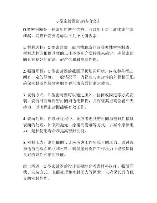
o型密封圈密封结构设计
O型密封圈是一种常用的密封结构,可以用于防止液体或气体泄漏。
其设计需要考虑以下几个关键因素:
1. 材料选择:O型密封圈一般由橡胶或硅胶等弹性材料制成,材料选择应根据具体的工作环境和介质特性来确定,确保密封圈具有良好的耐油、耐溶剂和耐高温性能。
2. 截面形状:O型密封圈的截面形状是圆环状,内径和外径之间有一定的厚度。
一般情况下,内径应与密封件的外径相匹配,确保密封圈能够紧密贴合并形成有效的密封效果。
3. 安装方式:O型密封圈可以通过压入、拉伸或固定等方式安装。
安装时应确保密封圈周边无损伤,并保证其正确位置和夹持力,以确保密封圈能够有效工作。
4. 表面处理:在设计过程中,还应考虑到密封圈与密封件接触表面的处理,如采用抛光、涂覆润滑剂等方式,以减小摩擦阻力、延长使用寿命和提高密封性能。
5. 密封压力:密封圈的设计应考虑工作环境下的压力,通过选择适当的截面形状和材料,确保密封圈在工作压力下能够保持良好的弹性和密封性能。
综上所述,O型密封圈的设计需要综合考虑材料选择、截面形状、安装方式、表面处理和密封压力等因素,以确保其具有优良的密封性能。
O形密封圈和密封圈槽尺寸选型设计计算参考O形密封圈和密封圈槽尺寸的合理匹配是延长密封圈无泄漏密封寿命的必要保证。
据此提出一种选配两者尺寸的理论计算方法,并以Y341—148注水封隔器所选密封圈的计算为例说明,根据不同的密封圈可以计算出相应的密封圈槽尺寸。
为保证密封圈长期有效地工作,还必须合理选择其压缩率、拉伸量和孔、轴配合精度等相关参数。
选取压缩率时,应考虑有足够的密封面接触压力、尽量小的摩擦力和避免密封圈的永久性变形。
顾及到一般试制车间的加工水平和井下工具主要是静密封的状况,建议密封面的轴、孔配合应优先选用H8/e8。
Selection of O-ring and calculation of O-ring groove sizeChen Aiping,Zhou Zhongya(Research Institute of Oil Production Technology,Jianghan Petroleum Administration,Qianjiand City,Hubei Province)Rational matching of O-rings and O-ringgrooves is of great importance to p[rolonging the service life of O-rings.A method for selecting O-ring was presented.The sizes of the O-ring gtoove can be calculated according to various O-rings.To ensure long-term and effective work of the ring,the compressibility,tensile dimension and bore-shaft matching accuracy should be properly selected. Subject Concept Terms:O-ring O-ring groove matching service life用O形密封圈(以下简称密封圈)密封是最常用的一种密封方式,然而至关重要的是如何正确地选择密封圈和设计密封圈槽尺寸。
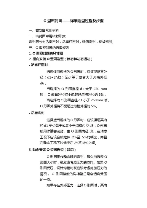
O型密封圈——详细选型过程及步骤一、密封圈常用材料二、密封圈常用密封形式密封圈分为活塞密封,活塞杆密封,端面密封,旋转密封。
三、O型密封圈的选型规则1.O型密封圈的尺寸图2.径向安装O型圈选型(静态和动态运动)•活塞杆密封选择适当规格的O形圈时,应该保证其外径(d1+2*d2)至少等于或者大于沟槽外径d6;当选择的O形圈直径d1大于250 mm 时, O形圈外径将不能超过沟槽外径的3%;当选择的O形圈直径d1小于250mm时,O形圈外径将不能超过沟槽外径的5%。
•活塞密封选择适当规格的O形圈时,应该保证其内径d1至少等于或者小于沟槽内径d3;O形圈被用作活塞密封,主O形圈内径d1,在动态工况下应该会被拉伸2%至5%的幅度,并且在静态工况下拉伸率在2%和8%之间。
3.轴向安装O型圈选型(静态)O形圈用作静态轴向密封,那么当选择O 形圈大小时,就应该考虑压力的方向。
如果O形圈受压,设计沟槽时就应该考虑施加压力的情况,O形圈接触的沟槽壁总是会远离受压的一侧。
如果存在外部压力,选择O形圈时,其内径d1就要比内沟槽直径d8小大约1%至3%。
如果存在内部压力,选择O形圈时,其外径(d1+2*d2)就要和外沟槽直径d7相等或者大约1%至2%。
4.轴向梯形沟槽安装O型圈选型(静态)梯形沟槽仅用于特殊情况下,例如在顶部安装的场合下,为了能够固定住O形圈。
其安装尺寸归纳在表17中。
梯形沟槽仅推荐用于横截面直径为3.53 mm的O形圈,O形圈内径等于平均沟槽直径减去O形圈横截面直径。
5.旋转密封O型圈选型在某些短运行周期的应用中,O形圈能够被用作密封轴上的旋转密封件。
同时,应该注意以下几点:•O形圈的安装必须符合旋转密封件的工作原理。
•旋转密封工作原理是基于拉伸的弹性密封圈受热会发生收缩(焦尔效应)。
根据常规的设计标准,O形圈内径d1将略小于轴径,由于摩擦而产生的热量将使密封圈产生更大的收缩,这样会使旋转轴上的压力增大而无法形成润滑油膜,导致摩擦力更大,结果就是磨损增加,密封圈提前失效。
O型密封圈的选型设计方案计算参考O型密封圈是一种常用的密封元件,广泛应用于各种机械设备和工业产品中。
在进行O型密封圈的选型设计时,需要考虑多个参数和因素,包括密封材料、尺寸、压力等,以确保密封效果和安全可靠性。
下面将介绍O型密封圈选型设计方案的计算参考。
首先,选择合适的密封材料是O型密封圈选型的基础。
常见的O型密封圈材料有橡胶、硅胶、丁腈橡胶、氟橡胶等。
不同的材料具有不同的耐温、耐腐蚀、耐油性等特性,需要根据具体的工作环境和介质选择合适的密封材料。
其次,尺寸的选取也十分重要。
O型密封圈的尺寸包括内径、外径和厚度。
内径的选取应根据密封件的要求,通常取密封零件孔直径的内径。
外径的选取应略大于密封零件孔的外径,以确保密封圈有足够的挤压变形量。
厚度的选取应根据压力、挤压量和材料的物理性质进行计算,以满足密封性能要求。
第三,压力是O型密封圈选型设计的重要参考参数之一、当压力较小时,可以选择低硬度的密封材料,以提供更好的密封性能。
当压力较大时,需要选择硬度较高的密封材料,以增加密封圈的抗压能力。
对于特殊压力要求的工作环境,需要做好弹性体结构强度的计算,以确保O型密封圈的可靠性。
最后,还需要考虑其他因素,如温度、介质特性和工作条件等。
温度对O型密封圈的弹性和硬度有很大影响,需要选择耐温性好的密封材料。
介质特性涉及到介质的腐蚀性、粘度等,需要选择具有相应抗腐蚀和耐热性能的密封材料。
工作条件包括振动、冲击、摩擦等,需要根据具体工况选择适合的密封材料和结构设计。
综上所述,O型密封圈的选型设计需要综合考虑密封材料、尺寸、压力、温度、介质特性和工作条件等多个参数和因素。
在实际应用中,需要根据具体的工况和要求进行综合分析和计算,以确保O型密封圈的选型设计能够满足密封效果和安全可靠性的要求。
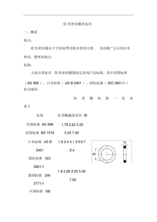
O形密封圈的选用一、概述特点:O 形密封圈由于它制造费用低及使用方便,因而被广泛应用在各种动、静密封场合。
标准:大部分国家对O 形密封圈都制定系列产品标准,其中美国标准(A S 568 )、日本标准( JIS B 2401 )、国际标准( ISO 3601/1 )较为通用。
O型圈标准一览表表 1标准O 型圈截面直径 W美国标准 AS 568 1.78 2.62 3.53英国标准 BS 1516 5.33 7.00日本标准 JIS B 1.9 2.4 3.1 3.55.724018.4国际标准ISO3601/11.82.653.55 5.30德国标准DIN7.003771/1中国标准GB3452.11.0 1.52.0 2.53.03.54.0 4.55.05.5优先的米制尺寸6.07.08.0 10.012.01.02 1.42 1.63美国标准 AS 568 1.83 1.98(900 系列) 2.08 2.21 2.462.953.00密封机理:O 形密封圈是一种自动双向作用密封元件。
安装时其径向和轴向方面的预压缩赋与 O 形密封圈自身的初始密封能力。
它随系统压力的提高而增大。
性能参数:静态密封工作压无挡圈时,最高可达力有挡圈时,最高可达20MPa40MPa动态密封;无挡圈时,最高可达;5MPa ;.用特殊挡圈时,最高可达有挡圈时,较高压力。
200MPa 。
运动速最大往复速度可达0.5m/s ,最大旋转速度可达 2.0m/s 。
度一般场合: -30 ℃~ +110 ℃;特殊橡胶: -60 ℃~ +250 ℃;温度旋转场合: -30 ℃~ +80 ℃介质见《橡胶密封件原料特性表》。
二、 O 形密封圈选择应考虑的因素1、工作介质和工作条件在具体选取 O 形圈材料时,首先要考虑与工作介质的相容性。
还须综合考虑其密封处的压力、温度、连续工作时间、运行周期等工作条件。
若用在旋转场合,须考虑由于摩擦热引起的温升。

T HE R IGHT S EALR ELEASE3.0 Y OUR G UIDE TO S EALING IN S EMICONDUCTOR P ROCESSINGThe proper design of an O-ring gland is a critical step in attaining optimum seal performance.This chapter provides the information necessary to select the recommended O-ring gland dimensions for a specific type of application, and to select the corresponding standard O-ring or Dovetail®Seal, along with its AS 568A dash number. The dash numbers are identical for O-rings and Dovetail Seals. (See Chapter 3 for information on creating part numbers for O-rings, and Chapter 4 for information on creating part numbers for Dovetail Seals.)The gland dimension recommendations presented in the tables of this chapter represent a significant amount of work done by SAE. These dimensions, when used in conjunction with standard AS 568A dash number O-rings, virtually assure satisfactory sealing functionality. A seal extraction groove is recommended whenever possible. This reduces the chance of damage to the gland when removing and replacing the seal.To determine recommended gland dimensions, standard O-ring sizes and AS 568A dash numbers, the designer should first select the intended sealing application from the following list and refer to the indicated page and tables.1.Static Face Seal, Rectangular Gland — Internal vacuum/external pressure, page 45.2.Static Face Seal, Rectangular Gland — Internal pressure/external vacuum, page 47.3.Static Face Seal, Dovetail Gland — Any pressure combination, page 48.4.Static I.D./O.D. Seal, Rectangular Gland — Any pressure combination, page 59.5.Dynamic I.D./O.D. Seal, Rectangular Gland —Any pressure combination, page 69.If the O-Ring Dash Size Is KnownStep 1.Locate the dash number in Table 7-10,beginning on page 50, to determine the O-ring’sdimensions from columns “B” and “C.”Step 2.Select the corresponding gland I.D. fromcolumn “D.”Step 3.Determine the appropriate gland cross-section dimensions, see Table 7-3, page 46.Step 4.To calculate the gland O.D., add 2X thegland width to the gland I.D.Selecting the O-Ring Dash SizeIf the O-ring dash size is not known and all glanddimensions are known:Step 1.Locate the dimensions of the gland’s cross-section in Table 7-3, page 46.Step 2.Select the corresponding O-ring dash sizeseries that matches the gland’s cross-sectiondimensions.Step 3.Locate the gland diameter within theO-ring number series in Table 7-10, page 50, todetermine the O-ring’s dash size.7ChapterSEAL GLAND DESIGNStatic Face Seal, Rectangular GlandInternal Vacuum/External PressureFigure 7-1If the exact gland dimensions cannot be located in these tables, a nonstandard O-ring may be required. Contact Greene, Tweed Engineering.To choose both the appropriate gland dimensions and the corresponding O-ring dash number:Step 1.From Table 7-3, page 46, select the desired O-ring cross-section and its corresponding AS 568A O-ring series. The cross-section selection should be based on the desired sealing footprint and allowable clearances within the hardware. A larger cross-section will result in a wider sealing footprint for a given cross-section squeeze percentage and should be generally preferred. However, larger cross-section seals will require a greater compressive load (see Semiconductor Seal Compound Selection Guide, pages 21–26).Step 2.From Table 7-10, page 50, based on hardware requirements, select the closest standard gland I.D. within the O-ring dash size series. Record the dash number. Note: Not all standard O-ring cross-sections are available for all diameters. If the desired gland I.D. cannot be found within the dash size series that has been selected, a different cross-section must be selected.Figure 7-2 Select Gland I.D. from Table 7-10, Column “D”Table 7-3: Standard Rectangular Face Sealing Gland Cross-Sectional DimensionsDimensions in inches.Step 3.From Table 7-3, page 46, select the appropriate gland cross-section dimensions. Tocalculate the gland O.D., add 2X the gland width to the gland I.D. determined in step 2.If the O-Ring Dash Size Is KnownStep 1.Locate the dash number in Table 7-10, page 50, to determine the O-ring’s dimensions fromcolumns “B” and “C.”Step 2.Select the corresponding gland O.D. fromcolumn “E.”Step 3.Determine the appropriate gland cross-section dimensions, see Table 7-6, page 48.Step 4.To calculate the gland I.D., subtract 2X the gland width from the gland O.D. Figure 7-5 Select Gland O.D. from Table 7-10, Column “E”Figure 7-4Static Face Seal, Rectangular Gland Internal Pressure/External VacuumSelecting the O-Ring Dash SizeIf the O-ring dash size is not known and all gland dimensions are known:Step 1.Locate the dimensions of the gland’s cross-section in Table 7-6, page 48.Step 2.Select the corresponding O-ring dash size series that matches the gland’s cross-section dimensions.Step 3.Locate the gland diameter within theO-ring number series in Table 7-10, page 50,to determine the O-ring’s dash size.If the exact gland dimensions cannot be located in these tables, a nonstandard O-ring may be required. Contact Greene, Tweed Engineering.To choose both the appropriate gland dimensions and the corresponding O-ring dash number:Step 1.From Table 7-6, page 48, select the desired O-ring cross-section and its corresponding AS 568A O-ring series. The cross-section selection should be based on the desired sealing footprint and allowable clearances within the hardware.A larger cross-section will result in a wider sealing footprint for a given cross-section squeeze percentage and should be generally preferred. However, larger cross-section seals will require a greater compressive load (see Semiconductor Seal Compound Selection Guide, pages 21–26).Step 2.From Table 7-10, page 50, based onhardware requirements, select the closest standard gland O.D. within the O-ring dash size series. Record the dash number. Note: Not all standard O-ring cross-sections are available for all diameters. If the desired gland O.D. cannot be found within the dash size series that has been selected, a different cross-section must be selected.Step 3.From Table 7-6, page 48, select the appropriate gland cross-section dimensions. To calculate the gland I.D., subtract 2X the gland width from the gland O.D. determined in step 2. Note: The O-ring dash size is the same, whetheryou are specifying an O-ring or a Dovetail®Seal.If the O-Ring Dash Size Is KnownStep 1.Locate the dash number in Table 7-10, page 50, to determine the O-ring’s dimensions from columns “B” and “C.”Step 2.Select the corresponding gland centerline diameter from column “F.”Step 3.Determine the appropriate gland cross-section dimensions, see Table 7-9, page 49. Static Face Seal, Dovetail GlandAny Pressure CombinationFigure 7-7Dimensions in inches.Selecting the O-Ring Dash Size If the O-ring dash size is not known and all gland dimensions are known:Step 1.Locate the dimensions of the gland’s cross-section in Table 7-9, page 49. Step 2.Select the corresponding O-ring dash size series that matches the gland’s cross-section dimensions. Step 3.Locate the gland’s centerline diameter within the O-ring number series in Table 7-10,page 50, to determine the O-ring’s dash size.If the exact gland dimensions cannot be locatedin these tables, a nonstandard O-ring may be required. Contact Greene, Tweed Engineering.Figure 7-8Select Gland Centerline Diameter from Table 7-10, Column “F” for All Dovetail GlandsTable 7-9: Standard Dovetail Face Sealing Gland Cross-Sectional DimensionsDimensions in inches.To choose both the appropriate gland dimensions and the corresponding O-ring dash number:Step 1.From Table 7-9, page 49, select the desired O-ring cross-section and its corresponding AS 568A O-ring series. The cross-section selection should be based on the desired sealing footprint and allowable clearances within the hardware. A larger cross-section will result in a wider sealing footprint for a given cross-section squeeze percentage and should be generally preferred. However, larger cross-section seals will require a greater compressive load (see Semiconductor Seal Compound Selection Guide, pages 21–26).Step 2.From Table 7-10, page 50, based on hardware requirements, select the closest centerline diameter within the O-ring dash size series from column “F.” Record the dash number. Note: Not all standard O-ring cross-sections are available for all diameters. If the desired centerline diameter cannot be found within the dash size seriesthat has been selected, a different cross-section must be selected.Step 3.From Table 7-9, page 49, select the appropriate gland cross-section dimensions.Table 7-10: Standard Face Sealing Diametrical Dimensions Dimensions in inches.Dimensions in inches.Dimensions in inches.Dimensions in inches.Dimensions in inches.Dimensions in inches.Dimensions in inches.Dimensions in inches.Dimensions in inches.Dimensions in inches.Dimensions in inches.Dimensions in inches.If the O-Ring Dash Size Is KnownStep 1.Locate the dash number in Table 7-14, page 61, to determine the O-ring’s dimensions from columns “B” and “C.”Step 2.Locate the appropriate gland dimensions in Table 7–14.Selecting the O-Ring Dash SizeIf the O-ring dash size is not known and all gland dimensions are known:Step 1.Locate the gland’s width inTable 7-13, page 60.Step 2.Select the corresponding O-ring dash size series that matches the gland’s width.Step 3.Locate the gland’s dimensions within the O-ring number series in Table 7-14, page 61, to determine the O-ring’s dash size.If the exact gland dimensions cannot be located in these tables, a nonstandard O-ring may be required. Contact Greene, Tweed Engineering.To choose both the appropriate gland dimensions and the corresponding O-ring dash number:Step 1.From Table 7-13, page 60, select the desired O-ring cross-section and its corresponding AS568A O-ring series. The cross-section selection should be based on the desired sealing footprint and allowable clearances within the hardware. A larger cross-section will result in a wider sealing footprint for a given cross-section squeezeStatic I.D./O.D. Seal, Rectangular Gland Any Pressure CombinationFigure 7-11Dimensions in inches.percentage and should be generally preferred.However, larger cross-section seals will require a greater compressive load (see Semiconductor Seal Compound Selection Guide, pages 21–26).Step 2.From Table 7-14, page 61, based on hardware requirements for O.D. sealing, select the closest standard bore diameter, from column “E,” within the O-ring dash size series. For I.D.sealing, select the closest standard tube diameter from column “G.” Record the dash number. Note: Not all standard O-ring cross-sections are available for all diameters. If the desired gland diameter cannot be found within the dash size series that has been selected, a different cross-section must be selected.Step 3.With the dash number determined in Step 2, follow the instructions on page 59 to determine complete gland dimensions.Figure 7-12 Static I.D./O.D. Sealing DetailsDimensions in inches.Table 7-14: Standard Static I.D./O.D. Seal Diametrical DimensionsTable 7-14: Standard Static I.D./O.D. Seal Diametrical Dimensions (continued)Dimensions in inches.Dimensions in inches.Dimensions in inches.Dimensions in inches.Dimensions in inches.Dimensions in inches.Dimensions in inches.If the O-Ring Dash Size Is KnownStep 1.Locate the dash number in Table 7-18, page71, to determine the O-ring’s dimensions from columns “B” and “C.”Step 2.Locate the appropriate gland dimensions in Table 7–18.Selecting the O-Ring Dash SizeIf the O-ring dash size is not known and all gland dimensions are known:Step 1.Locate the gland’s width in Table 7-17,page 70.Step 2.Select the corresponding O-ring dash size series that matches the gland’s width.Step 3.Locate the gland diameter within the O-ring number series in Table 7-18, page 71, to determine the O-ring’s dash size.If the exact gland dimensions cannot be located in these tables, a nonstandard O-ring may be required. Contact Greene, Tweed Engineering.To choose both the appropriate gland dimensions and the corresponding O-ring dash number:Step 1.From Table 7-17, page 70, select the desired O-ring cross-section and its corresponding AS 568A O-ring series. The cross-section selection should be based on the desired sealing footprint and allowable clearances within the hardware. A larger cross-section will result in a wider sealing footprint for a given cross-section squeeze percentage and should be generally preferred.Dynamic I.D./O.D. Seal, Rectangular GlandAny Pressure CombinationFigure 7-15Dimensions in inches.Step 2.From Table 7-18, page 71, based onhardware requirements for O.D. sealing, select the closest standard bore diameter from column “F”within the O-ring dash size series. For I.D. sealing,select the closest standard rod diameter from column “H” within the O-ring dash size series.Record the dash number. Note: Not all standard O-ring cross-sections are available for all diameters.If the desired gland diameter cannot be found within the dash size series that has been selected, a different cross-section must be selected.Step 3.With the dash number determined in Step 2, follow the instructions on page 69 to determine complete gland dimensions.Figure 7-16Dynamic I.D./O.D. Sealing DetailsDimensions in inches.Table 7-18: Standard Dynamic I.D./O.D. Sealing Diametrical DimensionsDimensions in inches.Dimensions in inches.Table 7-18: Standard Dynamic I.D./O.D. Sealing Diametrical Dimensions (continued)Dimensions in inches.Dimensions in inches.Dimensions in inches.Dimensions in inches.Contact UsGreene, Tweed CompaniesCorporate Headquarters2075 Detwiler Road, P.O. Box 305 Kulpsville, PA 19443-0305 USA Tel: +1.215.256.9521Fax: +1.215.256.0189Fluid Handling1910 Rankin RoadHouston, TX, 77073 USATel: +1.281.821.2094Tel: +1.800.820.9005Fax: +1.281.821.2696Oilfield1930 Rankin RoadHouston, TX, 77073 USATel: +1.281.765.4500Tel: +1.800.927.3301Fax: +1.281.765.4553 Palmetto, Inc.Denton Industrial Park25 Engerman Ave.Denton, MD, 21629 USATel: +1.410.479.2244Fax: +1.410.479.0836 Semiconductor2450 Scott Boulevard, Suite #312 Santa Clara, CA 95050 USA Tel: +1.408.492.1155Tel: +1.800.716.5316Fax: +1.408.492.0050 Greene, Tweed & Co., Limited Ruddington Fields RuddingtonNottingham, EnglandNG11 6JSTel: +44 (0) 115.9315.777 Fax: +44 (0) 115.9315.888 Greene, Tweed & Co., France S.A.19 rue des Beaux SoleilsBP 409 Osny95527 Cergy-Pontoise, Cedex FranceTel: +33 (0) 1.30.73.54.44 Fax: +33 (0) 1.30.73.45.75 Greene, Tweed & Co., GmbH Nordring 22D-65719 Hofheim am Taunus GermanyTel: +49 (0) 6192.92.99.50 Fax: +49 (0) 6192.90.03.16Greene, Tweed & Co. Italia S.r.l. Via Gaetano Crespi, 12I - 20134 MilanItalyTel: +39.02.21.05.17.1Fax: +39.02.21.05.17.30 Greene, Tweed & Co. Japan10F Tokuei Building33-7, Shiba 5-chome, Minato-ku Tokyo 108-0014 JapanTel: +81.3.3454.1050Fax: +81.3.3454.1040 Greene, Tweed & Co., Korea Ltd. 6F Yojin Bldg.7-3 Nonhyeon-Dong, Gangnam-Gu Seoul 135-010KoreaTel: +82.2.544.2077Fax: +82.2.544.2070 Greene, Tweed & Co.,Benelux B.V.Canadaweg 2a4661 PZ Halsteren NetherlandsTel: +31 (0) 164.612.123Fax: +31 (0) 164.610.030 Greene, Tweed & Co. Pte LtdNo 10 Admiralty Street#02-90/91 North Link building Singapore 757695Tel: +65.6555.4828Fax: +65.6555.5393Greene, Tweed & Co. (Suisse) SA Z.I. Le Bey 16CH - 1400 Yverdon SwitzerlandTel: +41 (0) 24.447.35.70Fax: +41 (0) 24.447.35.71。
o ring 橡胶密封截面
【最新版】
目录
1.O 型圈的概述
2.O 型圈的橡胶密封特点
3.O 型圈的截面设计
4.O 型圈的应用领域
正文
一、O 型圈的概述
O 型圈,顾名思义,是指截面呈 O 型的密封圈。
它是一种广泛应用于各种密封场合的橡胶制品。
O 型圈的主要作用是密封,防止流体、气体或固体颗粒在不同介质之间泄漏。
由于其结构简单、安装方便,以及优良的密封性能,O 型圈在各个行业都备受欢迎。
二、O 型圈的橡胶密封特点
O 型圈采用橡胶材料制作,具有以下优点:
1.良好的弹性:橡胶材料具有优异的弹性,可以适应不同形状的被密封表面,保证密封效果。
2.优异的耐磨性:橡胶材料具有很好的耐磨性能,可以减少摩擦,延长使用寿命。
3.良好的耐高低温性能:橡胶材料可以在广泛的温度范围内使用,从低温到高温都能保持良好的密封性能。
4.良好的耐化学性:橡胶材料具有较强的耐化学性,可以抵抗多种化学介质的侵蚀,保证密封效果。
三、O 型圈的截面设计
O 型圈的截面设计对其密封性能至关重要。
一般来说,O 型圈的截面越大,其密封性能越好。
但同时,过大的截面会增加 O 型圈的成本和安装难度。
因此,在设计 O 型圈的截面时,需要根据实际应用场景和要求,综合考虑密封性能、成本和安装难度等因素。
四、O 型圈的应用领域
O 型圈广泛应用于各种工业领域,如石油化工、机械制造、航空航天、汽车制造等。
在这些领域中,O 型圈主要用于密封轴、孔、阀门、管道等连接部位,防止流体、气体或固体颗粒的泄漏。
关于O-Ring的设计首先介绍一些O-Ring的材料O-Ring 即为常用的密封圈,常用材料为NBR,silicon等,以NBR为最常用。
下面先介绍NBR 这种材料月青橡膠(NBR)俗名或商品Nltrlleor Buna N化學名NltrlleButadi-ene物理性質:密度(gm/cm3) 1.00硬度範圍(Shore A) 20-90透氣性B-A電氣抵抗D-C香 B味C-B沾污抵抗C-B粘結性B-A機械性質抗張強度(max psi) 3,500摩擦抵抗 A撓曲抵抗B撕裂抵抗B衝擊抵抗 C變形能力B彈性B回彈性B應力釋放B※ A=最好B=平平C=劣D=不宜採用NBR O-Ring一般使用为黑色,其他特殊场合下有白色,透明和其他颜色,经过我与O-Ring厂家调查所得,因NBR橡胶制作O-Ring时加入一种黑色素(具体名称忘记了,待查),因此强度最高,其次为透明色。
其他颜色的O-Ring的强度稍微差一点,因此,一般常用黑色的。
一般的O-Ring设计,需要一些具体的参数,参数的决定对防水性的效果有很大的作用,一般都要经过计算所得。
下面介绍一些计算O-Ring具体参数的公式和技巧。
ID=Inner Diameter =O-Ring 内径CS=cross-section diameter= 横截面积C=O-Ring 线径压缩量O-Ring V olume=O-Ring的体积Gd =Groove Diameter (槽的内径)Bd =Bore Diameter (槽的外径)GW=Groove Width =槽宽Gland V olume=槽的体积主要为以上的,还有一些其他的如下:O-Ring 部分CSmax=Maximum Cross-Section DiameterUpper bound on the cross-section diameter for a given set of input requirements.CSmin=Minimum Cross-Section DiameterLower bound on the cross-section diameter for a given set of input requirements.CStol=Cross-Section ToleranceManufacturing tolerance on the O-Ring cross-section diameter.Cmax=Maximum Compression1 Upper bound for the cross-section compression when the O-Ring is seated in the gland; used as a design input.Cmin=Minimum Compression1 Lower bound for the cross-section compression when the O-Ring is seated in the gland; used as a design input.槽(Gloove)部分Btol =Bore Diameter ToleranceManufacturing tolerance on the bore diameter.Gtol =Groove Diameter ToleranceManufacturing tolerance on the groove diameter.介绍了O-Ring的具体参数后,以下是我多日寻找资料后总结的O-Ring的设计技巧,请高手们指教。
【论文摘要】O形密封圈和密封圈槽尺寸的合理匹配是延长密封圈无泄漏密封寿命的必要保证。
据此提出一种选配两者尺寸的理论计算方法,并以Y341—148注水封隔器所选密封圈的计算为例说明,根据不同的密封圈可以计算出相应的密封圈槽尺寸。
为保证密封圈长期有效地工作,还必须合理选择其压缩率、拉伸量和孔、轴配合精度等相关参数。
选取压缩率时,应考虑有足够的密封面接触压力、尽量小的摩擦力和避免密封圈的永久性变形。
顾及到一般试制车间的加工水平和井下工具主要是静密封的状况,建议密封面的轴、孔配合应优先选用H8/e8。
Selection of O-ring and calculation of O-ring groove sizeChen Aiping,Zhou Zhongya(Research Institute of Oil Production Technology,Jianghan Petroleum Administration,Qianjiand City,Hubei Province)Rational matching of O-rings and O-ringgrooves is of great importance to p[rolonging the service life of O-rings.A method for selecting O-ring was presented.The sizes of the O-ring gtoove can be calculated according to various O-rings.To ensure long-term and effective work of the ring,the compressibility,tensile dimension and bore-shaft matching accuracy should be properly selected.Subject Concept Terms:O-ring O-ring groove matching service life用O形密封圈(以下简称密封圈)密封是最常用的一种密封方式,然而至关重要的是如何正确地选择密封圈和设计密封圈槽尺寸。
o型圈密封设计标准O型圈密封设计标准。
O型圈密封是一种常见的密封元件,广泛应用于机械设备、汽车、航空航天等领域。
其密封性能直接影响着设备的可靠性和安全性。
因此,制定O型圈密封设计标准对于保证产品质量、提高生产效率具有重要意义。
首先,O型圈密封设计应符合国家标准和行业规范。
在设计过程中,应参照相关的国家标准和行业规范,确保设计方案符合法律法规的要求,同时满足用户的需求。
国家标准和行业规范通常包括O型圈的材料选用、尺寸标准、安装要求等内容,设计人员应严格遵守这些规定,以确保O型圈密封的质量和可靠性。
其次,O型圈密封设计应考虑工作环境和工作条件。
不同的工作环境和工作条件对O型圈密封的要求不同,设计人员应根据实际情况选择合适的O型圈材料和尺寸,以确保其在不同工作环境下的密封性能。
例如,在高温、高压、腐蚀性介质等特殊工况下,需要选择耐高温、耐高压、耐腐蚀的O型圈材料,同时设计合理的密封结构,以保证O型圈密封的可靠性。
另外,O型圈密封设计应注重安装和使用要求。
正确的安装和使用方法对于保证O型圈密封的性能至关重要。
设计人员应在设计过程中考虑到O型圈的安装位置、安装方式、使用条件等因素,为用户提供清晰的安装和使用说明,以确保O 型圈密封能够发挥最佳的密封效果。
最后,O型圈密封设计应进行严格的质量控制和检测。
在生产过程中,应对O 型圈密封进行严格的质量控制,确保材料和尺寸的符合标准要求,同时进行必要的检测和试验,以验证O型圈密封的密封性能和可靠性。
只有通过严格的质量控制和检测,才能保证O型圈密封的质量和可靠性,满足用户的需求。
综上所述,制定O型圈密封设计标准对于保证产品质量、提高生产效率具有重要意义。
设计人员应遵循国家标准和行业规范,考虑工作环境和工作条件,注重安装和使用要求,进行严格的质量控制和检测,以确保O型圈密封的质量和可靠性。
希望本文对O型圈密封设计标准的制定有所帮助,谢谢阅读。