信号发生器(0-10V,4-20mA)VICTOR 04 V、mA校验仪说明书
- 格式:doc
- 大小:309.50 KB
- 文档页数:6

信号发生器使用说明书杭州美控自动化技术有限公司U-S1-MKCN 4第4版杭州美控自动化技术有限公司前言感谢您购买我公司产品。
本手册是关于产品的功能、操作方法和故障处理方法等的说明书。
在操作之前请仔细阅读本手册,正确使用产品。
在您阅读完后,请妥善保管在便于随时取阅的地方,以便操作时参照。
注意本手册内容随仪表的性能及功能提升而改变,恕不提前通知。
本手册内容我们力求正确无误,如果您有任何疑问或发现任何错误,请与我们联系。
版本U-S1-M K CN4第四版2019年6月确认包装内容仪表提供以下标准附件,请确认附件是否齐全并完好无损。
序号物品名称数量备注1信号发生器12测试引线3一红一黑一黄3使用说明书14合格证15USB线16便携包1目录第一章概括 (1)1.1简介 (1)1.2主要功能 (1)1.3技术指标 (2)1.4规格 (3)第二章各部分名称及功能 (4)2.1接线端子 (5)2.2按键 (6)2.3液晶屏显示 (7)第三章信号输出 (8)3.1电压、有源电流输出 (8)3.24-20mA输出 (8)3.3热电偶输出 (9)3.4无源电流输出 (9)3.5电压、电流信号按显示量程输出或测量(免去量程换算) (10)第四章信号测量 (12)4.1电压、有源电流测量 (12)4.2无源电流测量 (13)4.3热电偶测量 (14)4.4调节阀门 (15)第五章可编程输出 (16)5.1分割输出功能(n/m) (16)5.2线性输出功能 (16)5.3自动步进功能 (18)第六章故障排除及仪表维护 (19)6.1故障排除 (19)6.2仪表维护 (20)第一章概括第一章概括1.1简介本信号发生器具有多种信号的测量和输出功能,包括电压、电流、热电偶信号,采用高清LCD液晶屏和功能分明的硅胶按键,显示清晰,操作简单,且具有待机时间长,精度高和可编程输出功能。
广泛应用于实验室、工业现场PLC与过程仪表、电动阀门等的调试。
综合电量变送器使用说明书标题:综合电量变送器使用说明书一、产品介绍综合电量变送器是一种将被测信号转换为标准电流信号或电压信号的设备,广泛应用于电力系统、自动化控制等领域。
本产品具有精度高、稳定性好、抗干扰能力强等特点。
二、技术参数1. 输入范围:AC 0-5A/0-1A,DC 0-20mA/4-20mA2. 输出范围:DC 4-20mA/0-5V/0-10V3. 精度等级:0.5%4. 工作温度:-25℃~70℃5. 存储温度:-40℃~85℃6. 相对湿度:≤95%(无冷凝)三、操作步骤1. 将变送器接入电源,并确保输入信号在规定的范围内。
2. 根据需要选择输出信号类型(电流或电压)。
3. 使用万用表检查输出信号是否正常。
四、注意事项1. 在安装和使用过程中,应避免强烈震动和冲击。
2. 请勿在潮湿、腐蚀性气体环境中使用。
3. 长期不使用时,应断开电源,存放在干燥、通风的地方。
4. 不得私自拆卸和维修,如有问题,请联系专业人员处理。
五、故障排除如果设备出现故障,首先检查电源和输入信号是否正常,然后按照以下步骤进行排查:1. 检查接线是否正确。
2. 检查变送器的工作环境是否符合要求。
3. 如果以上方法不能解决问题,请联系我们的售后服务部门。
六、联系方式如需了解更多关于综合电量变送器的信息,或有任何疑问和建议,欢迎随时联系我们:电话:XXX-XXXX-XXXX邮箱:***************感谢您选择我们的综合电量变送器,我们将竭诚为您服务!【注】此文档仅供参考,具体操作请参照实物设备及详细的产品手册。
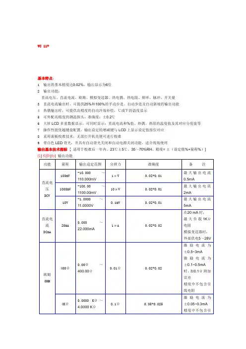
VC 11+基本特点:1输出的基本精度达0.02%,输出显示为6位2输出功能:直流电压、直流电流、欧姆、模拟变送器、热电偶、热电阻、频率、脉冲、开关量3直流电流输出时,可提供25%和100%的手动步进、自动步进及自动斜坡的输出功能4热偶输出时,可提供高精度的自动冷端补偿,℃或℉的温度显示5可外配高精度的测温探头,准确度:±0.2℃6大屏LCD多重数据显示,可同时显示:直流电流和%值、热偶、热阻的温度值及其对应分度值等7操作性能优越键盘配置,输出设定的增减键与LCD上显示设定值按位对应8采用面板校准技术,无需打开机壳便可进行校准9带白色LED背光,并具有自动背光关闭和自动电源关闭功能,适合现场使用输出基本技术指标[ 适用于校准后一年内、23℃±5℃、35~70%RH、精度= ±(设定值%+量程%)]技|术|指|标|输出功能功能量程输出设定范围分辨力准确度备注直流电压DCV 100mV-10.000~110.000mV1μV0.02+0.01最大输出电流0.5mA1000mV-100.00~1100.00mV10μV0.02+0.01最大输出电流2mA10V-1.0000~11.0000V0.1mV0.02+0.01最大输出电流5mA直流电流DCmA 20mA0.000~22.000mA1μA0.02+0.02在20 mA时,最大负载1KΩ电阻模拟变送器时,外部供电5~28V欧姆OHM 400Ω0.00Ω~400.00Ω0.01Ω0.02+0.02激励电流为±0.5~3mA激励电流为±0.1~0.5mA时,加0.1Ω附加误差精度中不包含引线电阻4KΩ0.0000 KΩ~4.0000 KΩ0.1Ω0.05+0.025激励电流为±0.05~0.3mA精度中不包含引线电阻40KΩ0.000 KΩ~40.000 KΩ1Ω0.1+0.1激励电流为±0.01mA精度中不包含引线电阻热电偶TC R0℃~1767℃1℃0~100℃: 1.5℃100~1767℃: 1.2℃采用ITS-90温标精度中不包含冷端补偿的误差S0℃~1767℃0~100℃: 1.5℃100~1767℃: 1.2℃K-200.0℃~1372.0℃0.1℃-200.0~-100.0℃: 0.6℃-100.0~400.0℃: 0.5℃400.0~1200.0℃: 0.7℃1200.0~1372.0℃:0.9℃E-200.0℃~1000.0℃-200.0~-100.0℃:0.6℃-100.0~600.0℃:0.5℃600.0~1000.0℃:0.4℃J-200.0℃~1200.0℃-200.0~-100.0 :0.6℃-100.0~800.0℃:0.5℃800.0~1200.0℃:0.7℃T-250.0℃~400.0℃-250.0~400.0℃:0.6℃N-200.0℃~1300.0℃-200.0~-100.0℃: 1.0℃-100.0~900.0℃:0.7℃900.0~1300.0℃:0.8℃B600℃~1820℃1℃600~800℃:1.5℃800~1820℃:1.1℃L-200.0℃~900.0℃0.1℃-200.0~0.0℃:0.7℃0.0~900.0℃:0.5℃U-200.0℃~600.0℃0.1℃-200.0~0.0℃:0.7℃0.0~600.0℃: 0.5℃热电阻RTD Pt100385-200.0℃~800.0℃0.1℃-200.0~0.0℃:0.3℃0.0~400.0℃:0.5℃400.0~800.0℃:0.8℃采用ITS-90温标Pt100、Cu50、Cu10激励电流为:±0.5~3mA激励电流为:±0.1~0.5mA时,加0.5℃附加误差Pt200、Pt500、Pt1000激励电流为±0.05~0.3mA精度中不包含引Pt200385-200.0℃~630.0℃-200.0~100.0℃:0.8℃100.0~300.0℃:0.9℃300.0~630.0℃:1.0℃Pt500 385-200.0℃~630.0℃-200.0~100.0℃:0.4℃100.0~300.0℃:0.5℃300.0~630.0℃:0.7℃线电阻Pt1000 385-200.0℃~630.0℃-200.0~100.0℃:0.2℃100.0~300.0℃:0.5℃300.0~630.0℃:0.7℃Cu10-100.0℃~260.0℃ 1.8℃Cu50-50.0℃~150.0℃0.6℃频率FREQ100Hz 1.00Hz~110.00Hz0.01Hz±2个字1~11 Vp-p方波电平准确度±5%读数+0.5V50%占空比负载>100KΩ1KHz0.100KHz~1.100KHz1Hz10KHz 1.0KHz~11.0KHz0.1KHz100KHz10KHz~110KHz2KHz±5个字脉冲PULSE 100Hz1~100000cycles1cyc±2个字1~11 Vp-p方波电平准确度±5%读数+0.5V50%占空比负载>100KΩ1KHz10KHz开关量SWITCH100Hz 1.00Hz~110.00Hz0.01Hz±2个字场效应管开关最大开关电流电压/电流:+28V/50mA1KHz0.100KH~1.100KHz1Hz10KHz 1.0KHz~11.0KHz0.1KHz100KHz10KHz~110KHz2KHz±5个字其他特性:1、内部温度补偿传感器RJC,测温范围0~50℃,补偿误差£±0. 5℃,2、测温探头准确度:±0.2℃,探头测温范围:-20~100℃3、输出端子间与地间施加最大电压:30Vp-p4、最大输出电流:约25mA一般特性:1工作温度及湿度0 to 50oC, ≤80%RH 无凝露40 to 50oC, ≤70%RH2储存温度及湿度-25 to 60oC, ≤90%RH无凝露3 显示及背光* 段式LCD双显示* 白色LED背光4 电源* 4 x 1.5V AAA碱性电池供电*CA充电器可对Ni-Hi电池充电(选购)*自动关机操作:可设定自动关机时间0~60分钟5 尺寸及重量205 × 95 × 42(mm),约500g6 附件表笔,保险丝产品型号:VICTOR 05 操作方式:自动量程产品名称:回路校验仪VICTOR 05 显示位数:5 1/2位产品分类:★00系列校验仪体积大小:手持式详细介绍:特点:输出和测量DCA(20mA)回路电流;测量DCV(28V)可模拟变送器的输出可提供24V回路电源提供24V回路电压并同时测量电流可进行开关的通和断测量可进行步进和零、满点的快速操作可产生快速和慢速的4~20mA电流自动斜波输出可mA和百分比显示5位LCD大字符显示,简便的键盘操作小巧、坚固、可靠,特别适合现场过程回路的校验、维修和故障诊断面板自动校准价格低廉|技|术|指|标|测量功能输入量程输入范围分辨力准确度说明电压28V-0.100~28.000V1mV±0.02%读数±2mV输入电阻2MΩ电流20mA-1.000~22.000mA0.001mA±0.02%读数±4uA输入电阻10Ω回路电流20mA-1.000~22.000mA0.001mA±0.02%读数±4uA提供24V回路电源输出功能输出量程输出范围分辨力准确度说明电流20mA0.000~22.000mA0.001mA±0.05%设定值±4uA 20mA最大负载1KΩ注1模拟变送器-20mA0.000~-22.000mA0.001mA±0.05%设定值±4uA20mA最大负载1KΩ注2回路电源24V±10%最大输出电流25mA |一|般|特|征|供电9V电池(ANSI/NEDA 1604A或IEC 6LR619V碱性)或AC电源适配器(VCPS)(选件)电池寿命约12小时/ 10mA条件下最大允许电压30V(各端子间及各端子对地)操作温度范围0℃~50℃操作湿度范围≤ 80%RH贮存温度范围≤ - 10℃~55℃贮存湿度范围≤ 90%RH尺寸200×100×40mm(加护套)重量550g(加护套)附件说明书、工业测试导线CF-36(探棒附鳄鱼夹)选件AC电源适配器(VCPS)安全符合IEC1010条款(国际电工委员会颁布的安全标准)注1:电池高于6.8V时,20mA最大负载1KΩ;电池在5.8V~6.8V之间,20mA最大负载700Ω。
Function GeneratorModel : GFG-3015Operation Manual82FG-30150MBiTable of ContentsPage1. Precautions......................................................................................................................... 2 2. Product Introduction.......................................................................................................... 5 3. Features .............................................................................................................................. 6 4. Specifications ..................................................................................................................... 7 5. Front and Rear Panels ..................................................................................................... 10 6. Operation .......................................................................................................................... 18 6.1 The First Step Setup For Instrument .................................................................... 18 6.2 The Setup of Output Function............................................................................... 18 6.3 The Setup of Frequency......................................................................................... 18 6.4 The Setup of Amplitude ......................................................................................... 19 6.5 The Setup of Offset ................................................................................................ 19 6.6 The Setup of Duty................................................................................................... 20 6.7 The Setting of STORE ............................................................................................ 20 6.8 The Setting of RECALL .......................................................................................... 20 6.9 The SHIFT Key and Function Keys ....................................................................... 21 6.10 Setup of LIN or LOG Sweep................................................................................. 21 6.11 Setup of AM Modulation ...................................................................................... 25 6.12 Setup of FM Modulation....................................................................................... 26 6.13 Setup of Trigger.................................................................................................... 28 6.14 Setup of GATE and BURST ................................................................................. 30 6.15 Setup of External Counter ................................................................................... 32 6.16 THE VCF Function ................................................................................................ 34 6.17 THE GCV Output Function................................................................................... 35 6.18 THE TTL Signal Output Function ........................................................................ 36 6.19 THE SYNC Signal Output Function..................................................................... 36 6.20 Remote Control - RS232 Interface ...................................................................... 36 6.21 Commands Syntax ............................................................................................... 38 6.22 The Commands of RS-232 Serial Interface ........................................................ 41 6.23 The Examples of the Communication Interface Software ................................ 44 6.24 The Error message of instrument ....................................................................... 47 7. Adjustment and Correction ............................................................................................. 48 7.1 Preparation.............................................................................................................. 48 7.2 Adjust and Check up the operation DC Voltage.................................................. 48 7.3 Adjusting Main Clock ............................................................................................. 49 7.4 Adjusting Sensitivity of counter ........................................................................... 49 7.5 Adjusting VCF Function 100:1 .............................................................................. 49 7.6 Adjusting Main Frequency , Duty Cycle and GCV Output Check ...................... 49 7.7 Adjusting Rise/Fall Time........................................................................................ 50 7.8 Adjusting Main Sine wave Harmonic Distortion.................................................. 50 7.9 Adjusting Modulation source ................................................................................ 50 7.9.1 Adjusting Rate and symmetry............................................................................ 50 7.9.2 Adjusting Sine wave Harmonic Distortion ........................................................ 51 7.10 Adjusting AM modulation .................................................................................... 51 7.11 Adjusting FM and Sweep Function..................................................................... 53 7.12 Adjusting Trigger Phase ...................................................................................... 55 7.13 Calibrating by Software ....................................................................................... 56 8. The Block Diagram and Description of the System ...................................................... 62iiEC Declaration of ConformityWeGOOD WILL INSTRUMENT CO., LTD.No. 7-1, Jhongsing Rd, Tucheng City,Taipei County 236, TaiwanGOOD WILL INSTRUMENT (SUZHOU) CO., LTD.No. 69, Lushan Road, Suzhou New District Jiangsu, Chinadeclares that the below mentioned productGFG-3015is herewith confirmed to comply with the requirements set out in the Council Directive on the Approximation of the Law of Member States relating to Electromagnetic Compatibility (89/336/EEC, 92/31/EEC, 93/68/EEC) and Low Voltage Equipment Directive (73/23/EEC, 93/68/EEC). For the evaluation regarding the Electromagnetic Compatibility and Low Voltage Equipment Directive, the following standards were applied:◎ EMC EN 61326-1: Electrical equipment for measurement, control and laboratory use –– EMCrequirements (1997+A1: 1998+A2: 2001) Conducted and Radiated Emissions Electrostatic Discharge EN 55011: 1998 class A EN 61000-4-2: 1995+A1:1998 Current Harmonic Radiated Immunity EN 61000-3-2: 2000 EN 61000-4-3: 1996+A1:1998 Voltage Fluctuation Electrical Fast Transients EN 61000-3-3: 1995 EN 61000-4-4: 1995 Surge Immunity ------------------------EN 61000-4-5: 1995 Conducted Susceptibility ------------------------EN 61000-4-6: 1996 Power Frequency Magnetic Field ------------------------EN 61000-4-8 : 1993 Voltage Dips/ Interrupts ------------------------EN 61000-4-11: 1994◎ SafetyLow Voltage Equipment Directive 73/23/EEC & amended by 93/68/EECSafety Requirements IEC/EN 61010-1: 2001GFG-3015p.11. PrecautionsGFG-3015 is specially designed for safety operation. It has passed through rigorous tests of inclement environment to ensure its reliability and good condition. The following precautions are recommended to insure your safety and keep the best condition of the equipment. (1) Safety Terms and Symbols The following terms and symbols may appear in this manual:! !This statement identifies conditions or practices that could result in injury or loss of life. This statement identifies conditions or practices that could CAUTION result in damage to this product or other properties. WARNINGThe following terms and symbols may appear on the product: This term indicates an immediately accessible injury hazard. DANGER This term indicates that an injury hazard may occur, but is WARNING not immediately accessible. This term indicates potential damage to this product or other CAUTION properties.!DANGER High voltage Protective Conductor Terminal ATTENTION refer to manual Double Insulated DANGER Hot surface Earth Ground Terminal(2) Do not place any heavy objects on the instrument under any circumstances.(3) Disassembling the instrument Due to the precision of this instrument, all the procedures of disassembling, adjusting, and maintenance should be performed by a professional technician. If the instrument has to be opened or adjusted under some unavoidable conditions, and to be managed by a technician who is familiar with GFG-3015. Once there is any abnormality, please contact our company or our distributor near you. (4) Power Supply AC input should be within the range of line voltage±15%, 50/60Hz. To prevent the instrument from burning up, be sure to check the line voltage before turning on power.p. 2GFG-3015(5) Grounding!WARNINGTo avoid electrical shock, the power cord protective grounding conductor must be connected to ground.GFG-3015 can be operated only with an earth grounded AC power cord that connects the case and ground well. This is to protect the user and the instrument from the risk of shock hazard. (6) Fuse Replacement!WARNINGFor continued fire protection, replace fuse only with the specific type and rating by qualified personnel. Disconnect the power cord before replacing fuse.The fuse blows only when there is any wrong on the instrument, which will stop working under this situation. Please find out the cause, then open the outside case (Please see the Figure (A), Figure (B) on below) and replace a proper fuse as listed below. Be sure to use the correct fuse before changing the applying location. F101 : T 0.8A/250V F100 : T 0.5A/250V Check the line voltage setting on the rear panel. If the line voltage setting does not match, Please change the line voltage setting according to the following steps: 1. Remove line cord from AC socket. 2. Switch the “AC line voltage switch” to correct setting with flat-blade screwdriver and reinsert.Figure (A) (7) Cleaning the Cabinet Disconnect the AC power cord before cleaning the instrument.Figure (B)Use a soft cloth dampened in a solution of mild detergent and water. Do not spray cleaner directly onto the instrument, since it may leak into the cabinet and cause damage. Do not use chemicals containing benzing, benzne, toluene, xylene, acetone, or similar solvents.GFG-3015p.3(8) Operation environment Indoor use Altitude up to 2000m Temperature to satisfy the specification : Operating temperature : Storage temperature : Relative humidity : Installation category: Pollution degree:18oC ~ 28oC (+64.4oF ~ +82.4oF) 0oC ~ 40oC (+32oF ~ +104oF) -10oC ~ 70oC (+14oF ~ 158oF) up to 90% when 0oC~35oC; up to 70% when 35oC~40oC CAT Ⅱ(The detail is as Table A) 2CAT Ⅳ CAT Ⅲ CAT Ⅱ CAT ⅠTable A For measurements performed at the source of the lowvoltage installation. For measurements performed in the building installation. For measurements performed on circuits directly connected to the low-voltage installation. For measurements performed on circuits not directly connected to Mains.(9) Place GFG-3015 in a location with a suitable environment as stated above free from dust, direct exposition of sunlight, and strong effect of magnetic fields. (10) For United KingdomAs the colours of the wires in mains leads may not correspond with the coloured markings identified in your plug/appliance, proceed as follows: The wire which is coloured Green and Yellow must be connected to the Earth terminal marked with the letter E or by the earth symbol or coloured Green or Green and Yellow. The wire which is coloured Blue must be connected to the terminal which is marked with the letter N or coloured Blue or Black. The wire which is coloured Brown must be connected to the terminal marked with the letter L or P or coloured Brown or Red. If in doubt, consult the instructions provided with the equipment or contact the supplier. This cable/appliance should be protected by a suitably rated and approved HBC mains fuse; refer to the rating information on the equipment and/or user instructions for details. As a guide, cable of 0.75mm2 should be protected by a 3A or 5A fuse. Larger conductorsNOTEThis lead/appliance must only be wired by competent persons.WARNINGTHIS APPLIANCE MUST BE EARTHEDIMPORTANTThe wires in this lead are coloured in accordance with the following codes: Green/Yellow :Earth Blue :Neutral :Live Brownwould normally require 13A types, depending on the connection method used. Any moulded mains connector that requires removal/replacement must be destroyed by removal of any fuse and fuse carrier and disposed of immediately, as a plug with bared wires is hazardous if engaged in a live socket. Any re-wiring must be carried out in accordance with the information detailed in this section.(Phase)p. 4GFG-30152. Product IntroductionThe frequency feedback method applied by GFG-3015 is a new technique that generates stable output frequency with extraordinary accuracy for Function Generator. The traditional function generators typically use integrating circuit and constant current circuit techniques that are easily affected by operation temperature or the quality of resistor or capacitor and other key components to occur poor frequency accuracy. The innovative design for GFG-3015 is to get rid of these problems. The frequency feedback system needs a compatible, powerful frequency counter. GW has designed his own full-function counter chip, GFC-9701, for this system with high frequency test range and full functions, including Period test, Duty test, Ratio test, Time interval, Pulse wide, direct display and direct connect with CPU system. GFG-3015 uses this Chip to read output frequency value at any time. Then CPU will modify the correct value of D/A converter immediately according to this value, so that the user can get a high accuracy frequency from GFG-3015 Function Generator. Besides, the GFG-3015 can also generate a high accuracy frequency to provide high frequency resolution.Graph1 indicates the fundamental construction of a frequency feedback system.D/A ConvertorVCOAMPO/PUser InterfaceCPUCounter (GFC-9701)Except the different design from the typical circuit, GFG-3015 system also has micro controller (CPU unit) equipping an additional RS-232 interface functions which will be used on any test system with other instrument or to be controlled by computer.GFG-3015p.53. FeaturesGFG-3015 is a functional Function generator that applies Frequency feedback control system technique and can generate high frequency accuracy with high resolution. Its main signal source can generate waveforms including sine wave, square wave, triangle wave, and ramp wave. There are additional features listed as follows: All digitized operation user interface Output Waveforms of Sine, Square, Triangle, Ramp, Pulse, AM, FM, Sweep, Trigger and Gate or Burst. Wide output frequency range 0.01Hz ~ 15MHz. High frequency accuracy 0.02% ± 5 count. Maximum frequency resolution 10mHz. Dual displays indicate frequency and amplitude or other necessary information. Built-in 6-digit INT/EXT Function Counter and up to 150MHz frequency range with high resolution. INT/EXT AM/FM Modulation with internal modulation signal output. LIN/LOG Sweep Mode with internal sweep signal output. VCF of 100:1 EXT Frequency Control. SYNC Output. TTL Output. Synchronization GCV Output. Variable DC Offset Control Output Overload Protection RS232 Interface Standardp. 6GFG-30154. SpecificationsOutput Waveforms Sine, Square, Triangle, ± Ramp, Pulse, AM, FM, Sweep, Trigger, Gate or Burst 1.5001MHz ~ 15.0000MHz …(100Hz) 150.01kHz ~ 1.50000MHz…(10Hz) 15.001kHz ~ 150.000kHz…(1Hz) 1.5001kHz ~ 15.0000kHz…(0.1Hz); 150.01Hz ~ 1.50000kHz…(10mHz) 15.01Hz ~ 150.00Hz…(10mHz) 1.51Hz ~ 15.00Hz…(10mHz) 0.01Hz ~ 1.50Hz…(10mHz) 0.02% ±5 CountFrequency Range 10mHz~15MHz in 8 Frequency Range (auto switch)Frequency ResolutionFrequency AccuracyOutput Impedance 50Ω ± 10% Range Amplitude Resolution Accuracy Unit Range DC Offset Resolution Accuracy Control Range Duty Resolution Accuracy Sync Output Sine Impedance Level Distortion 10.00V~0.01V (into 50Ω) 4 amplitude ranges | Vac peak | + | Vdc | < 5V 10mV(10.00V~0.01V) ≤3% ±5count at 10Hz~1MHz ≤10% ±5count at 1MHz~15MHz Vpp, Vrms, dBm ± 5V (into 50Ω) | Vac peak | + | Vdc | < 5V 10mV ≤3% ±3count at Amplitude Min. 80%:20%:80% to 1MHz 1% ≤1% to 1MHz at 50% Duty 50 Ω ±10% >1Vp-p open circuit ≤0.5%(-46dBc) From 10Hz~100kHz ≤-30dBc To 15MHz (Spec. applied form 1Vpp to 10Vpp) ±1% of period + 3ns <18nSec <1% of full scale output at 100HzSquare Triangle and RampAsymmetry Rise or Fall Time Linearity ErrorGFG-3015p.7Sweep ModeSweep Range Sweep Width Rate Sweep output Types Waveform Rate Frequency Range Rate Frequency Accuracy Rate Frequency ResolutionLinear or Log sweep 150kHz~15MHz 15kHz~1.5MHz 1.5kHz~150kHz 150Hz~15kHz 15Hz~1.5kHz 1.5Hz~150Hz 0.15Hz~15Hz 0.01Hz~1.5Hz >100:1(In Same Frequency Range) 0.01Hz~10kHz 0 to≥-5Vp-p into 10k Ω AM, FM, Sweep, Trigger(int/ext), Gate or Burst (Implement by Trigger Type) Sine, Square, Triangle, Ramp or Variable Symmetry Pulse 10mHz~10KHz in 3 Frequency Range (auto switch) 5%±1 countSymmetry Control 90:10:90 ; Resolution:1%10.0kHz~0.1kHz(100Hz) 99Hz~1Hz(1Hz) 0.99Hz~0.01Hz(0.01Hz) Symmetry 90%:10%:90%; Resolution:1% Symmetry Accuracy ±1 count(≤1%) Output Level Modulation Sine Wave Distortion Amplitude Modulation Depth Modulation Frequency Rate Carries -3dB Bandwidth External Sensitivity ≧1Vpp into 10kΩ load ≤2% from 10Hz to 10kHz0~100% 0.01Hz ~ 10kHz(INT) DC~1MHz(EXT) <100Hz to >5MHz ≤10Vpp for 100% modulationFrequency Modulation Deviation 0~±15% Modulation 0.01Hz ~ 10kHz(INT) DC ~ 50kHz(EXT) Frequency Rate External Sensitivity ≤5Vpp for 15% deviationp. 8GFG-3015Start/Stop Phase Range Rate Trigger-90º ~ +80º 0.01Hz~10kHzVCFFrequency Range 0.1Hz ~ 1MHz(Useful to 10MHz) Ext Trig Frequency DC to 1MHz,TTL compatible input level Range Gate or Burst Implement by Trigger setting. 100:1(0 to 10V± 1V) In Same Frequency Range Range Input Linearity <0.5% to 1MHz,<5% to 10MHz Input Impedance 10 k Ω ≧3Vpp LevelTTL Output GCV OutputFan-out >10 TTL Load To set the voltage between 0.2V to 2V as per different Frequency in Same frequency Range INT/EXT Switch Selector Range Accuracy Time Base Resolution Input Impedance Sensitivity 5Hz~150MHz EXT Time Base(10MHz) Accuracy ± 1 count ± 20ppm(23ºC ± 5ºC) after 30 minutes warm up The maximum resolution is 100nHz for 1Hz and 1Hz for 100MHz 1MΩ // 150pF ≤35mVrms(5Hz~100MHz); ≤45mVrms(100MHz~150MHz)Frequency CounterInterface Accessories Power Source Dimensions WeightRS232 GTL-101 × 2, Instruction Manual × 1, Power cord × 1 115/ 230V AC ±15%, Approx. 5kg 50/60Hz 290 (W) × 142 (H) × 346 (D) mmGFG-3015p.95. Front and Rear PanelsFront Panelp. 10GFG-30151POWER button Main Function keys: :Push the button to turn on the power, and the display is activated. Push again the button to turn off the power. Key is to set main output waveform in the cycle of Sine, Triangle and Square. When the key is pressed, the related waveform LEDs will light up accordingly.FUNC2Key is to set main frequency entry mode. Key in the desired value of frequency by using the number keys or Modify keys and Unit keys. When the key is pressed, the FREQ LED (on parameter display area A) will be flashing until other mode is set.FREQKey is to set main amplitude entry mode. Key in the desired value of voltage by using the number keys or Modify keys and Unit keys. When the key is pressed, the AMPL LED (on parameter display area B) will be flashing until other mode is set.AMPLKey is to set main output offset voltage entry mode. Key in the desired value of voltage by using the number keys or Modify keys and Unit keys. When the key is pressed, the OFFS LED (on parameter display area B) will be flashing until other mode is set.OFFSETKey is to set main output Duty Cycle entry mode. Key in the desired value of percentage by using the number keys or Modify keys and Unit keys. When the key is pressed, the DUTY LED (on parameter display area B) will be flashing until other mode is set.DUTY3Modulation/Sweep Function keys:Key is to start performing Amplitude Modulation, Frequency Modulation or Sweep function. When the key is pressed again, the functions will stop. When the key is pressed, the ON/OFF LED (on MOD/SWP Function LED area) will light up, press again the key, the LED will be off. These keys control the functions of sweep and modulation.MOD/ON SOURCEKey is to set Span of Modulation or Sweep entry mode and choose the source of modulation. If set to source choose function, must use Secondary Function mode.SPAN FMKey is to choose the type of modulation between AM and FM. If want to set to FM function, must use Secondary Function mode.AM INT/EXT RATEKey is to set Rate of Modulation, Sweep or Trigger entry mode and choose the signal source of Modulation, Sweep or Trigger. If want to set to signal, must use Secondary Functions mode.GFG-3015p.11STOPKey is to set Start Frequency of Sweep entry mode and Stop Frequency of Sweep entry mode. If set to Stop Frequency of Sweep entry mode, must use Secondary Functions mode.START LOG SKey is to choose the type of Sweep between liner sweep and LOG sweep. If set to LOG sweep, must use Secondary Function mode.LIN S SWP CF SYMKey is to set the Duty cycle of Modulation, Sweep or Trigger source entry mode. Key in the desired value of percentage by using number keys or modify keys and Unit keys. If want to set to center frequency of Sweep function that must use Secondary Functions mode. When the key is pressed, the SYM LED (on parameter display area B) will be flashing until other mode is set. When you use center frequency entry mode then the CF LED (In parameter display area A) will be flashing until other mode is set. The detail operation of these keys. Please refer to the instruction in next Chapter.RECL4System keys:Key is to save or reload the setup parameters of the instrument into or take out from memory; the selected DEFAU numbers is from 0 to 9, up to 10 groups.STORKey is to start performing RS232 interface. Press the key then use rotational knob to change function states (ON or OFF). Press the key again then use rotational knob to change the Baud rate. The cycle order is in 300, 600, 1200, 2400, 4800, 9600 and 19200 sequence. If set the instrument to default state, must use Secondary Function mode. Key is to set the Secondary Functions mode. When the key is pressed, the instrument will choose Secondary Function and the SHIFT LED will light up.SHIFTDEFAU RS232 RS232For example, press SHIFT value of the instrument.5+Hz/Vppcan recall the defaultUnit keys:In ‘Normal’ mode, these keys are used to assign the unit and to set the entered value. For example, you can use dBm and Vpp to set the output amplitude. They can be used to set frequency (MHz, kHz, Hz), OFFSET, and PHASE, etc. In STOR or RECL modes, they are used as ‘Enter’.DEG/% MHz/dBKHz/Vrmsp. 12GFG-30156Entry keys:9 . To and keys are used to input value. A unit key should be pressed to set the entered value. 0key is blank space that used to delete the entered value entirely and the other function is minus key .-/BK SP7Modify keys:Keys are used to change the digit of input value. User can use the Rotate knob for increasing or decreasing that digit.◄ ►Key to terminate the function of all Modify keys until user press this key again. When the key is pressed, the HOLD LED will light up until the key is pressed again.HOLD8Trigger Function keys:Key is to start performing Trigger function mode. If the key is pressed again, the function will stop. When the key is pressed, the ON/OFF LED (In Trigger Function LED area) will light up until the key is pressed again (The LED will light off).TRIG ONKey is to choose the type of Trigger, Single-trigger or multi-trigger. When the key is pressed, the MULT or SINGL LED (In Trigger Function LED area) will light up accordingly.SIGL/MUTKey is to set the phase of trigger function entry mode. Key in the desired value of percentage by using number keys, modify keys and Unit keys. When the key is pressed, the PHASE LED (In parameter display area B) will be flashing until other mode is set.PHASETRIG EXTKey is to choose the Trigger signal source, internal orexternal. When the key is pressed, the EXT LED (In Trigger Function LED area) will light up accordingly until the key is pressed again (The LED will light off).INT/EXT9Counter Function key:10Parameter display Area (A):Key is to set the Gate time of External counter GATE function. The cycle order is according to 0.01s, 0.1s, 1s, and 10s. When the key is pressed, the Gate time LEDs will light up according user’s wish. The other function is to choose input signal source of counter, internal or external, by using Secondary Function mode. The 6-digit Parameter display presents the parameter values and information about the current status and unit. The START LED light on indicated that the value of display was Start frequency of sweep function right now. The STOP LED light on indicated that the value of display was Stop frequency of sweep function right now. The CF LED light on indicated that the value of display was center frequency of sweep function right now.GFG-3015p.1311Parameter display Area (B):121314Waveform Function LEDs Counter Functions LEDs Modulation/Sweep Function LEDs: : :The FREQ LED light on indicated that the value of display was main output frequency right now. The RATE LED light on indicated that the value of display was rate frequency of sweep or modulation or trigger function right now. The SPAN LED light on indicated that the value of display was Span frequency of sweep function right now. The MHz, kHz, Hz and mHz LED light on indicated that unit according current value of display. This 4-digit Parameter display presents the parameter values and information about the current status and unit. The AMPL LED light on indicated that the value of display was main output amplitude right now. The OFFS LED light on indicated that the value of display was main output DC offset voltage right now. The DUTY LED light on indicated that the value of display was main output duty cycle right now. The SPAN LED light on indicated that the value of display was span frequency of modulation function right now. The SYM LED light on indicated that the value of display was modulation signal duty cycle of sweep or modulation or trigger function right now. The PHASE LED light on indicated that the value of display was phase of trigger function right now. The STOR LED light on indicated that the value of display was save group number right now. The RECL LED light on indicated that the value of display was reload group number right now. The V, rms, dBm kHz, Hz, % and DEG LED light on indicated that unit according current value of display. These LEDs indicate the figure of main output waveform and the current operation functions. These LEDs indicate the GATE TIME of external counter and the current value. These LEDs indicate the current status of Sweep and Modulation and the current operation functions. The AM LED lights on to indicate the setting status of amplitude modulation function. The FM LED lights on to indicate the setting status of frequency modulation function. The LIN LED lights on to indicate the setting status of liner sweep function. The LOG LED lights on to indicate the setting status of LOG sweep function. The Sine, Triangle and Square LED light on indicated that according Modulation source waveform. The EXT LED lights on to indicate the external sweep or modulation signal source. The ON/OFF LED lights on to indicate that the sweep or modulation function is enabled.p. 14GFG-3015。
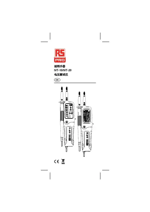
说明手册IVT-10/IVT-20 电压测试仪CN1. 安全安全信息为确保对测试仪进行安全操作和检修,请遵循以下说明。
如不遵守警告规定,可能会导致严重人身伤亡。
-避免独自一人作业,以便获得他人帮助。
若无法保证操作人员安全,必须将测试仪从检修区移出并防止使用测试仪。
- 使用前需确保仪器在测试前后均功能完好(如使用已知电压源)。
- 不得将仪器连接到高于 750V 的电压。
- 在断开电压源之前,不得打开电池盖。
- 当测试仪处于以下情况时,无法保证安全:- 存在明显损伤未采用所需的测量指标已在不当条件下存放太长时间已受到机械应力的影响(如在运输过程中)。
- 使用此仪器时必须遵守所有相关劳保法规。
- 如有一项或若干项功能出现故障、无法实现任何功能或测试仪看上去受到了损坏,则不可再使用测试仪。
- 使用该测试仪时,只可触碰探头手柄,不得触碰探针头(金属部分)。
- 如果测试仪不能正常工作或是湿的,则不可使用测试仪。
- 必须按照说明卡中的规定(包括环境条件)使用测试仪,必须遵守干燥环境使用说明,否则可能无法全面保护测试仪。
- 在裸导体或母线周围使用时,务必格外谨慎小心。
如果接触到导体,可能会导致电击。
- 在电压条件高于 50V 交流 rms 或 110V 直流电压时,须谨慎使用。
这些电压条件存在电击危险。
12. 符号与功能具体符号请参考测试仪上和说明手册中的标记 电击风险请参考说明手册+ or - + 直流或 –直流测量设备受到双绝缘或强化绝缘保护电池接地±交流测量遵守 EU 指令高压探测功能列表–交流电压–直流电压–连续性–电阻(仅在 IVT-20 上)–单极相位测试–三相电源相位旋转–频率测试(仅在 IVT-20 上)–自动测试–探头尖端焊炬–1 米防摔–IP 65 保护–电源自动打开/关闭–2/4 mm 可选探头尖端23. 交流/直流 V 测量交流 VV直流IVT-20:安全指示灯可报告高于 50 V 交流和 120 V 直流的危险电压。
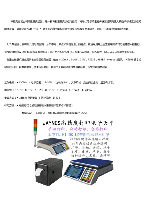
称重变送器也叫做重量变送器,是一种将物理量变换成电信号,将毫伏信号输出的传感器经隔离放大转换成标准直流信号的变送器。
通常采用SMT工艺,针对工业过程的电阻应变式信号传感器而设计制造,适用于于不同规格称重传感器。
A/D转换器,具有输入信号范围宽,分辨率高,零点和满载温漂小的特点。
模块采用螺丝固定安装方式可方便的嵌入控制柜。
该模块通信协议采用Modbus通信协议,可方便的连接各种PLC称重控制系统,组态软件,DCS,以及电脑集中监控系统。
称重变送器广泛应用于各类称重信号变送,输出4-20mA,0-10V,0-5V,RS232,RS485,modbus通讯。
JNS996数字式称重放大器,具有精度高,抗干扰性能好,解决了大量程称重传感器难标定,标定不准确的问题。
工作电源:◆DC24V (电源范围:18-36V),功率约8W ,文章较长,点击阅读全文,后面有惊喜。
额定输出:0~5v、0~10v、0~±5v、0~±10v、0~20mA 0~10mA、4~20mA安装方式:◆35mm导轨安装(防护等级:IP40)标定方法:◆砝码标定(通过按键输入重量值标定零点和量程)◆数字标定(无需砝码,直接输入称重传感器的参数进行标定)称重处理:◆AD采样方法:Delta-Sigma方法◆AD采样速率:100次/秒◆内部分辨率:1/260000◆显示分辨率:1/50000◆精度:0.005& F.S称重接口: ◆输入灵敏度:≥0.25uV/d◆输入信号范围:-30.5mV~+30.5mV◆零点信号范围:-30.5mV~+30.5mV◆传感器激励电压:10V◆传感器驱动能力:4只350Ω的传感器开关量接口:◆输入接口2个:置零、去皮、毛重/净重、打印等选其一◆输出接口2个:可设置两个高低位开关量输出信号输出:◆模拟量输出:4-20mA,0-10V,0-5V 任选其一◆数字量输出:RS232,RS485 (通讯协议:MODBUS RTU)其它参数:◆使用环境温度:-20℃~45℃◆相对湿度:10&~90& 无冷凝◆显示:6位高亮度红色数码管◆指示灯:6个◆按键数量:6个◆重量:0.4kg数据恢复:◆客户设置好参数后,将参数保存,以后万一将参数调乱,可以通过数据恢复功能,直接恢复。
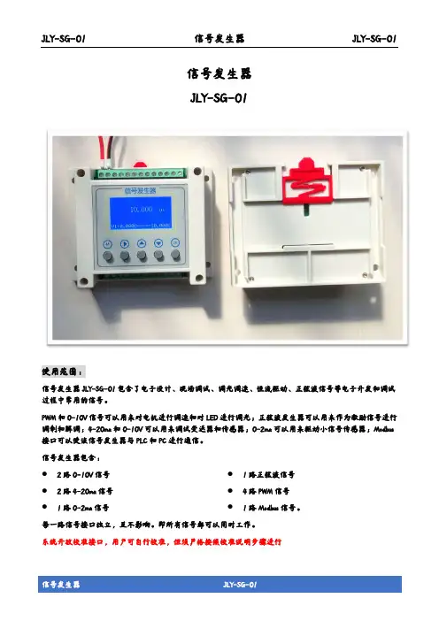
JLY-SG-01 信号发生器 JLY-SG-01信号发生器JLY-SG-01使用范围:信号发生器JLY-SG-01包含了电子设计、现场调试、调光调速、恒流驱动、正弦波信号等电子开发和调试过程中常用的信号。
PWM和0-10V信号可以用来对电机进行调速和对LED进行调光;正弦波发生器可以用来作为激励信号进行调制和解调;4-20ma和0-10V可以用来调试变送器和传感器;0-2ma可以用来驱动小信号传感器;Modbus 接口可以使该信号发生器与PLC和PC进行通信。
信号发生器包含:●2路0-10V信号 ●2路4-20ma信号 ●1路0-2ma信号 ●1路正弦波信号 ●4路PWM信号 ●1路Modbus信号。
每一路信号接口独立,互不影响。
即所有信号都可以同时工作。
系统开放校准接口,用户可自行校准,但须严格按照校准说明步骤进行JLY-SG-01信号发生器 JLY-SG-01JLY-SG-01主要特点:● 仪器小巧,告别笨重。
可手持、可桌面放置、可导轨安装亦可墙壁安装。
● 温度补偿,良好的稳定性,超高的精度 ● 工业化设计,响应速度快● 信号接口丰富且每路信号独立运行,互不干扰。
一机在手,调试无忧 ● 高亮度点阵屏,硅胶按键,手感颜值爆表 ● 模拟信号最低可以调整到0,使信号更完整技术指标:● 4-20ma:精度±0.5%,负载小于300Ω ● 0-2ma:精度±0.5%,负载小于3k Ω ● 0-10V: 精度±0.5%,负载大于5k Ω ● 正弦波信号:频率精度±0.5%,负载大于10K Ω,峰峰值:4.2V。
其频率可设置范围:50Hz ~ 999.999KHz ● PWM 信号:频率精度±0.5%,负载大于10K Ω,VH>2.4V,VL<0.6V,Vmax=5V。
其频率可设置范围:100Hz ~ 200KHz● 12~15VDC 供电,最大电流500ma ● 工作温度:0~50℃ ● 存储温度:-20~65℃ ● LCD12864显示屏,硅胶按键● 参数可通过MMI 按键设置亦可通过Modbus 设置 ● 预留用户校准接口,当仪表误差大时可自行校准(须严格按照校准操作章节进行操作)接线图:操作说明:●开机/关机操作关机状态下,短按“M”系统开机;开机状态下,长按“M”3s,待显示屏变暗后松开按键即可关机。

第一章简介警告使用仪器前,请仔细阅读使用说明书。
概述本仪器是一台智能型多功能接地电阻测试仪。
本仪器采用数字信号处理技术,直接提取接地测量信号,具有高分辨率、高精度、很好的抗干扰能力等特点,可准确测量接地电阻值。
本仪器能执行标准的三极和四极接地电阻测量以外,还具有两极接地电阻测量和计算土壤电阻率的功能。
●设计符合以下安全标准:IEC61010-1(CAT Ⅲ 600V、污染等级Ⅱ)IEC61557-1、5(交流1000V和直流1500V以下低压配电系统电气安全)●基本测量功能2极/3极/4极法接地电阻测量土壤电阻率(ρ)测量●接地电阻测量采用交流激励测试,4种测试频率(94Hz、105Hz、111Hz、128Hz),可手动选择,从而减低干扰源影响。
●辅助接地电阻测试功能测试并显示辅助接地电阻。
●辅助接地电阻上限警告显示功能由于辅助接地电阻高而可能无确测试时显示警告。
●电阻测量中自动量程,超量程显示OL。
●干扰电压过高指示功能。
●串联干扰电压测试功能。
●白色背光功能便于在阴暗光线下工作。
●可去除测试线的剩余电阻(Rk)的设定功能。
●可设定土壤电阻率测试时的辅助接地棒间隔,设置围:1m~30m。
●具有可设定时间的自动背光关闭和自动电源关闭功能。
●操作方便的数据记录功能、查询记录数据,部存储器可独立存储100个(组)测量数据。
小巧、坚固的结构设计,便于双手作业的颈带,简便的人机操作,适应现场运输和恶劣的环境。
开箱检查检查货物,查看它在运送途中是否受损。
检查货物是否齐全,并保存包装材料以供以后运送使用。
本仪器所提供的标配附件和选购附件列在下面。
选购附件可以根据需要购买。
标配附件• 测试导线6m(黑色)1条• 测试导线6m(绿色)1条• 测试导线15m(红色)1条• 测试导线30m(蓝色)1条• 辅助接地棒4个• 使用说明书1本• 碱性电池1.5V(LR6)8节• 软携带包:C安全警告本仪器的设计、制造和检测均达到IEC61010-1、IEC61557-1、IEC61557-5安全标准要求,本手册包括确保仪器的安全使用及保证仪器的安全状态,使用者所必须遵守的警告和安全条例。
二线制交流电流变送器的设计步骤作者信继华前言根据广大网友的要求,特别是刚走出学校门的大学生们,在进行电路设计时,面对新的项目,无法下手,不知道具体的设计思路从何处怎样开展,到处求人提供资料,而大部分都不能实用。
本人经常收到网友的求助,要求提供设计思路。
但本人的答复仅对某个项目提出一点建议,而针对广大网友来讲,起不到启发作用!原因是,很多网友不希望本人公开答复,一是担心提出的问题太低级,招来某些“闲人”的热潮冷讽。
二是存在人们固有的保守思想的影响,不想让别人知道他的“秘密项目”。
用现在比较时髦的话来讲,称“保护知识产权”。
知识产权是有时效性的!过分强调保护知识产权,对于整个社会的发展是有害而无益的!比如本人在网上转载多年前公开发行的专业书籍,就引来不少非议。
而提出非议的并不是作者本人!我想,作者写书的目的并非纯粹为了经济利益吧?在这里提醒大家一下,任何项目,从设计到实施完成,都是一个系统工程,并非是某一个专业能够独立完成的。
它需要不同专业的密切配合,齐心协力,共同攻关,最终的成功必定是一个集体智慧的结晶!为了向大家提供一个具体的设计思路,这里将本人十年前设计的一个小项目的具体步骤公开出来,希望能够给大家今后进行设计项目时起到一点引导作用。
同时也希望专家学者给本人提出批评指导意见。
二线制交流电流变送器的设计步骤已知大电流电流互感器均将不同的电流转换成0~5A的交流电流进行现场显示。
而进行远距离传送时,必须将该电流转换成标准直流电流信号4~20mA,才能进行传送。
市场上此类交流电流变送器大都采用“四线制”的方法:即交流电源线二根,直流电流信号线二根。
而我们设计的是“二线制交流电流变送器”则只采用二根电线:即在给变送器内的电路提供直流电源的同时,将根据0~5A交流电流变化的变送输出标准直流电流信号4~20mA远传至控制室显示或进入计算机内处理后在显示器画面上显示。
设计思路1,选择低功耗元器件,在满足功能要求的前提下,尽量简化电路,满足二线制仪表的要求。
信号发生器本人介绍一下信号发生器的使用和操作步骤.1、信号发生器参数性能频率范围:0.2Hz ~2MHz粗调、微调旋钮正弦波, 三角波, 方波, TTL 脉波0.5" 大型 LED 显示器可调 DC offset 电位输出过载保护信号发生器/信号源的技术指标:波形正弦波, 三角波, 方波, Ramp 与脉波输出振幅>20Vp-p (open circuit); >10Vp-p (加 50Ω负载) 阻抗50Ω+10%衰减器-20dB+1.0dB (at 1kHz)DC 飘移<-10V ~ >+10V, (<-5V ~ >+5V 加 50Ω负载)周期控制 1 : 1 to 10 : 1 continuously rating显示幕4位LED显示幕频率范围0.2Hz to2MHz(共 7 档)频率控制Separate coarse and fine tuning失真< 1% 0.2Hz ~ 20kHz , < 2% 20kHz ~ 200kHz频率响应< 0.2dB 0.2Hz ~100kHz; < 1dB100kHz~2MHz线性98% 0.2Hz ~100kHz; 95%100kHz~2MHz对称性<2% 0.2Hz ~100kHz上升/下降时间<120nS位准4Vp-p±1Vp-p ~ 14.5Vp-p±0.5Vp-p 可调上升/下降时间<120nS位准>3Vpp上升/下降时间<30nS输入电压约 0V~10V ±1V input for 10 : 1 frequency ratio输入阻抗10kΩ (±10%)交流 100V/120V/220V/230V ±10%, 50/60Hz电源线× 1, 操作手册× 1, 测试线 GTL-101 × 1230(宽) × 95(高) × 280(长) mm,约 2.1 公斤信号发生器是为进行电子测量提供满足一定技术要求电信号的仪器设备。
回路校准仪1引言回路校准仪(以下简称校准仪)是一个由电池供电,能测量和输出电参数和物理参数的手持便携式仪器。
可用于测量直流电压、直流电流;模拟输出直流电流。
2标准配置以下所列的项目均包含在您的校准仪内,如果您发现校准仪有损坏或缺少一些东西,应立即与购买单位联系。
欲订购更换零件或备件,请参见本手册15.3所列的用户可更换的备件清单。
•工业测试导线(H000001-00) 2副•VC05S说明书_中文(E1000272-00) 1本•保险管(D610027-00) 2只•锁扣钥匙(C110221-00) 1只• 5号碱性电池 3节3安全信息用户应按照本说明书的指示使用校准仪,否则校准仪所提供的保护措施可能会受到损坏。
对于没有按照所给的安全警示信息进行操”指出可能对用户构成危险的情况或行为;“小心”指出可能对校准仪或被测试设备造成损坏的情况或行为。
有关校准仪及本说明书所采用国际电气符号的解释,请参阅表1。
表 1. 国际电气符号为避免受到电击或人身伤害:•切勿在端子之间或任何端子和接地之间施加超过校准仪上标示的额定电压。
•使用前,先测量一已知电压以确认校准仪工作正常。
•请遵循所有设备的安全步骤。
•切勿使用已损坏的校准仪。
使用前应检查校准仪的外壳是否有断裂或缺少塑料件。
特别注意接头周围的绝缘。
•根据测量要求选择正确的功能和量程档。
•使用校准仪以前应确定电池门已关紧。
•打开电池门以前应先把校准仪的测试线拆下。
•检查测试线是否有损坏或暴露的金属。
检查测试线是否导通。
使用仪表前应把损坏的测试线更换。
•使用探头时,手指不要碰到探头的金属触点。
手指应保持在探头的护指装置后面。
•接线时,应先接公共线然后再接带电的测试线。
拆线时,应先拆除带电的测试线。
•若仪表工作失常,请勿使用。
保护措施可能已遭破坏。
若有疑问,应把仪表送去维修。
•切勿在爆炸性的气体、蒸汽或灰尘附近使用本仪表。
•校准仪应使用 3 节 AA LR6 的电池供电,电池应正确地安装在仪表壳内。
4-20mA电流信号转成0-5V或0-10V电压信号解决方法:1.采用专用的电流转电压芯片,或者隔离放大器(要求精度高,抗干扰时)如:MAXIM MAX472深圳顺源公司的ISO系列产品/2.自己搭建电路,节省成本,但不推荐直接串联精密电阻的方式用运放搭建电路就非常好给个地址: /html/zonghejishu/2007/0925/2621.html1、 0-5V/0-10mA的V/I变换电路图1是由运放和阻容等元件组成的V/I变换电路,能将0—5V的直流电压信号线性地转换成0-10mA的电流信号,A1是比较器.A3是电压跟随器,构成负反馈回路,输入电压Vi与反馈电压Vf比较,在比较器A1的输出端得到输出电压VL,V1控制运放A1的输出电压V2,从而改变晶体管T1的输出电流IL而输出电流IL又影响反馈电压Vf,达到跟踪输入电压Vi的目的。
输出电流IL 的大小可通过下式计算:IL=Vf/(Rw+R7),由于负反馈的作用使Vi=Vf,因此IL=Vi/(Rw+R7),当Rw+R7取值为500Ω时,可实现0-5V/0-10mA的V/I转换,如果所选用器件的性能参数比较稳定,运故A1、A2的放大倍数较大,那么这种电路的转换精度,一般能够达到较高的要求。
2、 0-10V/0-10mA的V/I变换电路图2中Vf是输出电流IL流过电阻Rf产生的反馈电压,即V1与V2两点之间的电压差,此信号经电阻R3、R4加到运放A1的两个输入端Vp与Vn,反馈电压Vf=V1-V2,对于运放A1,有VN=Vp;Vp=V1/(R2+R3)×R2,VN=V2+(Vi-V2)×R4/(R1+R4),所以V1/(R2+R3)×R2=V2+(Vi-V2)×R4/(R1+R4),依据Vf=V1-V2及上式可推导出:若式中R1=R2=100kΩ,R1=R4=20kΩ,则有:Vf×R1=Vi×R4,得出:Vf=R4/R1×Vi=1/5Vi,如果忽略流过反馈回路R3、R4的电流,则有:IL=Vf/Rf=Vi/5Rf,由此可以看出.当运放的开环增益足够大时,输出电流IL与输入电压Vi满足线性关系,而且关系式中只与反馈电阻Rf的阻值有关.显然,当Rf=200Ω时,此电路能实现0-10v/0-10mA的V/I变换。
0 10V转换为4 20mA电路分析0~10V转换为4~20mA电路分析信老师,您好~我是机械电子专业的学生,正在做“电流转换电路”的设计,0~10V转换为4~20mA,我遇到了很大的问题,就是不会推导输入电压和输出电流的关系式,我附上了题目和相关的图,您能就以下两个思考题帮我分析一下么,然后给我回复。
我在中华工控网也给您回帖了~万分感谢,有机会来北京我请您吃饭,呵呵~[附题]简要说明:为提高抗干扰能力,模拟信号经常采用4~20mA电流信号进行远距离传输。
本电路的功能是将0~10V的输入电压信号ui转换成4~20mA的电流信号Io供长距离传输用。
思考题:1(电路中电位器W1、W2和W3的作用各是什么,怎样相互配合调整才能使输出范围为4~20mA。
2(图中第2级放大器的增益应如何计算,(难点)回答:1,首先说明,按照你提供的参数是不能正常工作的~ 2, N1在输入10V时会反相饱和导通。
原因是你在抄袭电路时,将R2,W1的阻值搞错了。
3,第1级N1是反相衰减是放大器,应该将输入的0,10V电压信号变成负0,1.6V的信号。
增益A=-(RF/Rf)UiR F=R2+W1=1.5KΩ+200ΩRf=R1=10KΩ此时 A=-(1.6/10)Ui=0.16(0~10V)=0~1.64, 第2级N2是反相加法器,在接受前级输入的-0~1.6V同时与零点基准电压W2取来的-4V电压相加后,再与反馈电压VR11(0.4~2V)比较取得平衡,从而达到稳定输出电流的目的。
加法器电路是一个典型的反相加法放大器,输出电压Eo可以有以下公式表示: Eo=-[Vi1(RF/Rf1)+Vi2(RF/Rf2)]式中 Eo 输出电压Vi1 前级来的信号电压(-0,1.6V)Vi2 系统零点基准调节电压(-4V)RF 加法器反馈电阻(10KΩ+600Ω)Rf1 前级信号输入电阻(10KΩ)Rf2 基准调节电压信号的输入电阻(100KΩ) 由于后一级电路要求,反相加法放大器是一个1:1的加法电路。