麻省理工电化学教程系列1
- 格式:pdf
- 大小:317.95 KB
- 文档页数:7


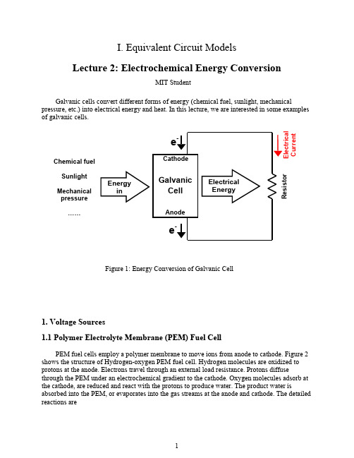
I. Equivalent Circuit ModelsLecture 2: Electrochemical Energy ConversionMIT StudentGalvanic cells convert different forms of energy (chemical fuel, sunlight, mechanical pressure, etc.) into electrical energy and heat. In this lecture, we are interested in some examples of galvanic cells.Current Chemical fuelSunlightMechanicalpressure……1. Voltage Sources1.1 Polymer Electrolyte Membrane (PEM) Fuel CellPEM fuel cells employ a polymer membrane to move ions from anode to cathode. Figure 2 shows the structure of Hydrogen-oxygen PEM fuel cell. Hydrogen molecules are oxidized to protons at the anode. Electrons travel through an external load resistance. Protons diffuse through the PEM under an electrochemical gradient to the cathode. Oxygen molecules adsorb at the cathode, are reduced and react with the protons to produce water. The product water is absorbed into the PEM, or evaporates into the gas streams at the anode and cathode. The detailed reactions areFigure 1: Energy Conversion of Galvanic CellH2 O2gas gas2OResistorAnode (oxidation reaction, produces electrons):Cathode (reduction reaction, consumes electrons):Net reaction:The equivalent circuit of PEM fuel cell is shown in Figure 3. The resistors and capacitors are related to different effects:R a D: gas diffusion at anodeR c D: gas diffusion at cathodeR a i: interfacial charge transfer at anodeR c i: interfacial charge transfer at cathodeR M: ion transfer in membraneC a i: interfacial charge storage at anodeC c i: interfacial charge storage at cathodeFigure 2: Hydrogen-oxygen PEM fuel cella c0 R ext1.2 Solid Oxide Fuel Cell (SOFC)Solid oxide fuel cells are a class of fuel cell characterized by the use of a solid oxidematerial as the electrolyte. In contrast to PEM fuel cells, which conduct positive hydrogen ions (protons) through a polymer electrolyte from the anode to the cathode, the SOFCs use a solid oxide electrolyte to conduct anions, e.g. negative oxygen ions, from the cathode to the anode, as shown in Figure 2. The electrochemical oxidation of the oxygen ions thus occurs on the anode side. The detailed reactions areAnode (oxidation reaction, produces electrons):Cathode (reduction reaction, consumes electrons):Net reaction:Figure 3: Equivalent circuit of PEM fuel cellH 2O 2gas gasH 2 Resistor2. Current Sources2.1 Silicon p-n Junction Solar CellBefore we learn silicon solar cell, we need to understand some basic concepts of semiconductor physics.A fundamental result of solid-state physics states that in semiconductor electrons with specific energies are allowed to stay in sharply define bands leaving bandgaps of forbidden energies in between. As shown in Figure 5, the two key bands around the fundamental bandgap are given special names. The band immediately below is called the valence band while the band immediately above is called the conduction band. In pure silicon, all states in valence band are occupied by electrons while all states in conduction band are empty at temperature of 0 K. At high temperatures a few states of the conduction band may actually be occupied by electrons. The electrons in the partially filled conduction band can move around in response to an applied voltage. In addition, there are empty states, called holes, in valence band which now allow electrons to move about.The band structures of silicon can be changed by doping. Doping brings foreign atoms which do not change the silicon lattice very much but can donate or accept electrons. The atom from Column V of the periodic table can “donate” one of its electrons to the conduction band and become positively charged, which is called donor. The semiconductor with doped donors is call n-type semiconductor. The atom from Column III of the periodic table can “accept” abonding electron and become negatively charged, which is called acceptor. The semiconductorFigure 4: Solid oxide fuel cellwith doped acceptors is call p-type semiconductor. Electron states associated with donor and acceptor atoms can be represented in the energy band diagram as shown in Figure 6. Donor states are inside the forbidden gap slightly below the conduction band edge at E D . The reason is that it only takes a small amount of energy to release the electron the conduction band. Similarly, acceptor states are represented slightly above the valence band at E A , as a little energy will result in the release of a hole to the valence band.Egg(E)Figure 5: Band structure of Intrinsic Si at 0KFigure 6: Band structure of doped Si. (a) n type. (b) p type.An ideal p-n junction is a semiconductor structure where the doping level abruptly changes from n-type with a uniform donor concentration to p-type with a uniform acceptor concentration,shown in Figure 7. Electrons on the n-side will tend to flow towards the p-side since they are presented with empty states at the same energy. At the same time, holes on the p-side will flow towards the n-side where there are lots of available states at the same energy. Once thermal equilibrium has been established and charge redistribution has stopped, a charge dipole has developed across the junction. This results in net positive charge on the n-side and net negation charge on the p-side. So there is a build-in electric field at the junction.When the p-n junction absorb a photon with hv>E g, a new electron-hole pair is produced. The build-in electric field drives the electron to the n-side and the hole to the p-side. If we connect the p-n junction to the external circuit, we will “harvest” the electron-hole pair current at electrodes.lightR extFigure 7: p-n junction solar cellThe equivalent circuit of p-n junction solar cell is shown in Figure 8(a). A p-n junction diode is in parallel with a current source where I p is the photocurrent. Figure 8(b) shows the I-V curve of the diode. In forward bias, large current is easy to pass. But in reverse bias, only a small saturation current I s is allowed. The I-V relation of diode can be calculate asAssuming R int=0, the I-V relation isp =0 (dark environment), the solar cell performs as a diode. When I p>0 (light environment), the open circuit voltage isI D V I Dsreverse biasforward bias (a) (b) VI p >0V 0I p =0I p +I s0 I s I p IFigure 8: Equivalent circuit of p-n junction solar cellFigure 9: Current-voltage relation of p-n junction solar cell2.2 Graetzel Cell (dye-sensitized solar cell)A dye-sensitized solar cell is based on a semiconductor formed between a photo-sensitized anode and an electrolyte, as shown in Figure 10. The cell has three primary parts. On the top is a transparent anode made of fluorine-doped tin dioxide (S n O2:F) deposited on the back of a (typically glass) plate. On the back of the conductive plate is a thin layer of titanium dioxide(T i O2), which forms into a highly porous structure with an extremely high surface area. T i O2 only absorbs a small fraction of the solar photons. The plate is then immersed in a mixture of a photosensitive ruthenium-polypyridine dye and a solvent. After soaking the film in the dye solution, a thin layer of the dye is left covalently bonded to the surface of the T i O2. A separate backing is made with a thin layer of the iodide electrolyte spread over a conductive sheet, typically platinum metal.Sunlight enters the cell through the transparent S n O2:F top contact, striking the dye on the surface of the T i O2. Photons striking the dye with enough energy to be absorbed will create an excited state of the dye, from which an electron can be "injected" directly into the conduction band of the T i O2, and from there it moves by diffusion (as a result of an electron concentration gradient) to the clear anode on top. Meanwhile, the dye molecule has lost an electron and the molecule will decompose if another electron is not provided. The dye strips one from iodide in electrolyte below the T i O2, oxidizing it into triiodide. This reaction occurs quite quickly compared to the time that it takes for the injected electron to recombine with the oxidized dye molecule, preventing this recombination reaction that would effectively short-circuit the solar cell. The triiodide then recovers its missing electron by mechanically diffusing to the bottom of the cell, where the counter electrode re-introduces the electrons after flowing through the external circuit.R extFigure 10: Dye-sensitized solar cellFigure 11 shows the equivalent circuit of dye-sensitized solar cell. The basic idea is still the same: “harvest” the electron-hole pairs from the absorbed photons.0 c 02.3 Electro Kinetic Energy ConversionA pressure-driven fluid flow through micro channels carries a net electrical charge with it, inducing both a current and a potential when the charge accumulates at the channel ends. These so-called streaming currents and streaming potentials can drive an external load and therefore represent a means of converting hydrostatic energy into electrical power, as shown in Figure 12. The notion of employing such electro kinetic effects in an energy conversion device is called electro kinetic energy conversion. Physical modeling of electro kinetic energy conversion is needed to guide the optimization of these properties. The relations of electro kinetic phenomena can be described by the following equations:where P is pressure, Q is flow rate, V is voltage and I is current. K H is hydrodynamicconductivity of the porous material, K E is electric conductivity and S is electro kinetic coupling.The detailed model of electro kinetic energy conversion will be discussed in Lecture 33.R extFigure 11: Equivalent circuit of dye-sensitized solar cellFigure 12: Electro Kinetic Energy ConversionMIT OpenCourseWare10.626 / 10.462 Electrochemical Energy SystemsSpring 2011For information about citing these materials or our Terms of Use, visit: /terms.。

电化学基础教程(第二版)版权页•内容提要•前言•第一版前言•第1章绪论•1.1 电化学简介•1.2 电化学的历史•1.3 电化学研究领域的发展•1.4 本书结构与学习方法•复习题•第2章导体和电化学体系•2.1 电学基础知识•2.2 两类导体的导电机理•2.3 电化学体系•2.4 法拉第定律•2.5 实际电化学装置的设计•复习题•第3章液态电解质与固态电解质•3.1 电解质溶液与离子水化•3.2 电解质溶液的活度•3.3 电解质溶液的电迁移•3.4 电解质溶液的扩散•3.5 电解质溶液的离子氛理论•3.6 无机固体电解质•3.7 聚合物电解质•3.8 熔盐电解质•复习题•第4章电化学热力学•4.1 相间电势与可逆电池•4.2 电极电势•4.3 液体接界电势•4.4 离子选择性电极•复习题•第5章双电层•5.1 双电层简介•5.2 双电层结构的研究方法•5.3 双电层结构模型的发展•5.4 有机活性物质在电极表面的吸附•复习题•第6章电化学动力学概论•6.1 电极的极化•6.2 不可逆电化学装置•6.3 电极过程与电极反应•6.4 电极过程的速率控制步骤•复习题•第7章电化学极化•7.1 电化学动力学理论基础•7.2 电极动力学的Butler-Volmer模型•7.3 单电子反应的电化学极化•7.4 多电子反应的电极动力学•7.5 电极反应机理的研究•7.6 分散层对电极反应速率的影响——ψ1效应•7.7 平衡电势与稳定电势•复习题•第8章浓度极化•8.1 液相传质•8.2 扩散与扩散层•8.3 稳态扩散传质规律•8.4 可逆电极反应的稳态浓度极化•8.5 电化学极化与浓度极化共存时的稳态动力学规律•8.6 流体动力学方法简介•8.7 电迁移对扩散层中液相传质的影响•8.8 表面转化步骤对电极过程的影响•复习题•第9章基本暂态测量方法与极谱法•9.1 电势阶跃法•9.2 电流阶跃法•9.3 循环伏安法•9.4 电化学阻抗谱•9.5 滴汞电极与极谱法•复习题•第10章实际电极过程•10.1 电催化概述•10.2 氢电极过程•10.3 氧电极过程•10.4 金属阴极过程•10.5 金属阳极过程•复习题•附录标准电极电势表(298.15K,101.325kPa)•习题答案•参考文献•符号表。
《理工电化学教案》PPT课件第一章:绪论1.1 课程介绍介绍课程的背景、目的和意义阐述电化学的基本概念和原理1.2 电化学的发展历程回顾电化学的发展历程和重要人物介绍电化学的重要发现和里程碑1.3 电化学的应用领域列举电化学在各个领域的应用实例强调电化学在现代科技和工业中的重要性第二章:电化学基础理论2.1 电解质溶液介绍电解质溶液的基本概念和性质阐述电解质溶液的导电机制2.2 电极反应介绍电极的分类和电极反应的类型解释氧化还原反应与电极反应的关系2.3 电化学电池介绍电池的基本结构和原理阐述电池的电动势和能量转换过程第三章:电化学测量技术3.1 电化学测量原理介绍电化学测量的基础知识和原理阐述电位、电流和电量等参数的测量方法3.2 电化学测量仪器介绍常见的电化学测量仪器及其工作原理强调仪器的使用方法和注意事项3.3 电化学测量实验设计一些典型的电化学测量实验引导学生进行实验操作和数据分析第四章:电化学应用案例分析4.1 电镀技术介绍电镀的基本原理和工艺流程分析电镀技术的应用实例和实际问题4.2 腐蚀与防护阐述金属腐蚀的机理和类型介绍腐蚀防护的方法和技术4.3 电化学传感器介绍电化学传感器的原理和结构分析电化学传感器在各个领域的应用案例第五章:综合案例分析与实践5.1 案例分析提供一个综合性的案例,分析电化学技术在该领域的应用引导学生思考和解决实际问题5.2 实践操作设计一个实验项目,让学生亲自动手操作强调实验安全注意事项和实验数据的准确性5.3 成果展示与讨论让学生展示实验结果和分析报告组织学生进行讨论和交流,促进知识的共享和深入学习第六章:电化学动力学6.1 电化学动力学基本方程介绍电化学动力学的基本方程,如Butler-Volmer 方程解释电化学动力学中的速率和平衡概念6.2 电化学动力学参数的测定介绍电化学动力学参数的测定方法分析实验数据,确定电化学动力学参数6.3 电化学动力学在工程中的应用阐述电化学动力学在工程中的应用实例强调电化学动力学在电池设计和优化中的重要性第七章:电化学腐蚀与防护7.1 电化学腐蚀的基本原理介绍电化学腐蚀的定义和机理解释电化学腐蚀与化学腐蚀的区别7.2 电化学腐蚀的影响因素分析影响电化学腐蚀的因素,如电解质、金属材料等探讨环境因素对电化学腐蚀的影响7.3 电化学腐蚀的防护方法介绍电化学腐蚀的防护方法,如阴极保护、涂料等强调电化学腐蚀防护方法的选择和应用第八章:电化学传感器8.1 电化学传感器的原理与结构介绍电化学传感器的原理和结构解释电化学传感器的工作原理和检测机制8.2 电化学传感器的应用领域阐述电化学传感器在各个领域的应用实例强调电化学传感器在环境监测和生物检测中的重要性8.3 电化学传感器的研发与挑战探讨电化学传感器的研发趋势和新技术分析电化学传感器面临的挑战和限制第九章:电化学应用案例分析9.1 电化学在能源领域的应用介绍电化学在能源领域的应用实例,如燃料电池、锂离子电池等分析电化学技术在能源领域的优势和挑战9.2 电化学在环境领域的应用阐述电化学在环境领域的应用实例,如废水处理、污染治理等强调电化学技术在环境保护中的作用和潜力9.3 电化学在生物医学领域的应用介绍电化学在生物医学领域的应用实例,如电化学发光、生物传感器等分析电化学技术在生物医学领域的优势和挑战第十章:综合案例分析与实践10.1 综合案例分析提供一个综合性的案例,分析电化学技术在该领域的应用引导学生思考和解决实际问题10.2 实践操作设计一个实验项目,让学生亲自动手操作强调实验安全注意事项和实验数据的准确性10.3 成果展示与讨论让学生展示实验结果和分析报告组织学生进行讨论和交流,促进知识的共享和深入学习重点和难点解析一、第二章的电极反应和第三章的电化学测量技术:这两章是电化学基础,理解电极反应的类型和电化学测量的原理对于后续章节的学习至关重要。
mit 多孔电极上的气泡形成过程多孔电极上的气泡形成过程多孔电极是一种电化学实验中常用的电极材料,其特点是表面有许多微小孔洞。
当多孔电极处于电解质溶液中时,会发生气体电化学反应,形成气泡。
气泡形成的过程可分为三个阶段:起始阶段、成长阶段和脱离阶段。
起始阶段:当多孔电极刚刚接触到电解质溶液时,电解质溶液中的阳离子和阴离子会向多孔电极表面迁移。
在多孔电极表面,由于孔洞的存在,电解质溶液形成了微小的溶液通道。
正离子会沿着溶液通道快速向多孔电极内部扩散,而负离子则会集中在电解质溶液与多孔电极表面接触的位置。
当正离子在多孔电极内部通过扩散到达孔洞的底部时,它们会与电极表面的电子发生还原反应,形成气体。
这是气泡形成的起始阶段。
成长阶段:在起始阶段,气泡形成后会在孔洞底部逐渐增大。
在成长阶段,电解质溶液中的正离子会继续向孔洞内部扩散,与电极表面的电子发生还原反应,进一步形成气体。
由于气体的体积增大,气泡在孔洞内部不断增长。
在成长阶段,气泡的增长速度和溶液中的离子浓度有关。
如果离子浓度较高,气泡会较快地增长。
同时,气泡表面的张力也会影响气泡的大小。
脱离阶段:当气泡在多孔电极表面逐渐增大到一定程度时,气泡会与电解质溶液中的其他离子发生碰撞,导致气泡从多孔电极表面脱离。
在这一阶段,气泡会逐渐上升,直至浮到溶液表面。
除了以上三个阶段,气泡形成的速度还与温度、电流密度、电解质浓度等因素有关。
例如,随着温度的升高,电解质溶液的动力学黏度会降低,电解质中离子的迁移速度会加快,从而提高气泡形成的速率。
多孔电极上的气泡形成过程是一个复杂而重要的现象。
通过研究气泡形成过程,可以更好地理解电化学反应机制,并在相关的领域中应用该知识,如电池、电解、电解制氢等。
同时,对气泡形成过程的深入研究还可以为相关领域的工程设计提供理论依据,帮助优化实验条件,提高反应效率。
I. Equivalent Circuit ModelsLecture 1: Basic Physics of Galvanic CellsMIT Student (and MZB)In this lecture, we give an overview of electrochemical cell operations, and define basic terminologies frequently used in a discussion of electrochemical cell operations.1. Electrochemical Cells and Their OperationsFaradaic Reaction : An electrochemical reaction that involves charge transfer Electrochemical Cell : Two half reactions involving charge transfer, connected via anelectrolyte (conducting ions) and an external circuit (conducting electrons)Figure 1. Galvanic Operation of an Electrochemical CellIn a galvanic cell, electrons and ions flow spontaneously, converting chemical energy into electrical energy (and heat). As shown in Figure 1, in galvanic cell operation, an oxidation reaction occurs at anode, producing electrons. On the other hand, at cathode, a reduction reaction occurs, consuming electrons on the electrode surface. Since the electrons are not able to move through the electrolyte, they flow via external circuits from anode to cathode, making a currentin a direction from cathode to anode. In electrolyte phase, oxidized species migrates from anode to cathode, and reduced species migrates from cathode to anode in net amount, respectively. Inan electrolytic cell , charges flow in the opposite direction, driven by an external voltage which inputs electrical energy to be stored as chemical energy. The sign convention of current is defined to have a positive sign for galvanic cells. Therefore, in an electrolytic cell operation, a current has a negative value.The followings are two examples of electrochemical cell construction: Example 1: PEM fuel cellAnodeCathode H2g→2H++2e−Net Reaction 12O2g+2H+ +2e− →H2O l H2g+12O2gElectrolytepolymer electrolyte membrane (PEM)→ H2O l Example 2: Li-ion batteryAnodeCathode LiC6→ Li++e−+C6Net ReactionLi++e−+CoO2→LiCo O2Electrolyte Li organic liquid containing LiPF C6+CoO2→LiCoO2+C6(“rocking chair battery”) 6 salt dissolved2.Equivalent CircuitIt is possible to represent an electrochemical cell using an equivalent circuit model. We will learn how to model physical components of an electrochemical cell with circuit element representations later on in this course. For now, we focus on operation behaviors of circuits, given an equivalent circuit model of an electrochemical cell.A galvanic cell can be represented by an equivalent circuit as following:Figure 2. An Equivalent Circuit Model of a Galvanic Cellwhere VaoVco : Standard Equilibrium Half-cell Potential of Anode : Standard Equilibrium Half-cell Potential of CathodeRa Rc : Interface Resistance at Anode : Interface Resistance at CathodeRel x Resistance through ElectrolyteRe t :: External Circuit ResistanceEquivalently, the above equivalent circuit may be simplified by lumping circuit elements into fewer representative elements.Figure 3. Lumped Equivalent Circuit Model of a Galvanic CellWhereVo=Vco−VaoRint =Ra+Rel+ Ra : Open Circuit Voltage (OCV) of a Cell : Internal ResistanceNote that standard equilibrium half-cell potentials (Vao , and Vco ) are sometimes denoted electrochemistry, but that notation is refrained since it may be confusing with an electric field. The standard equilibrium half-cell potentials may be either positive or negative, as long as Eo open circuit voltage, is positive (for a galvanic c Vo in , ell).According to the Kirchhoff’s law, (1) where V is the cell voltage . The cell voltage is a function of current, I, state of charge, Q, which will be defined in Lecture 3, and other electrochemical variables. The cell voltage, inthermodynamic terms, means the free energy difference of net cell reaction per chargetransferred. The thermodynamic interpretation of cell voltage will be discussed in Lecture 7.(2)When the external resistance is zero, we obtain short circuit current :(3)Given a current and a cell voltage, we can calculate a cell power, P, which is electrical work done by cell per unit time.(4) Assuming a constant internal resistance, the dependence of cell voltage and cell power to the current can be plotted as following:Electrolytic Galvanic Super GalvanicRegime Regime RegimeP < 0 P > 0 P < 0I < 0 I > 0 I > I SV > V o0 < V < V o V < 0Electrical Energy Chemical Energy Chemical + Electrical Energy→ Chemical Energy Storage → Electrical Energy + Heat Loss → Heat Losse.g. charging a Li-ion battery e.g. discharging a battery e.g. forcing the battery toby applying a reverse through an external load discharge faster than I S byvoltage applying a voltage externally Figure 4. Cell Voltage and Power Behavior as a Function of CurrentTable 1. Different Regimes of Cell Operation and FeaturesMore realistic fuel cells do not have constant internal resistance. Rather, they have nonlinear contributions from several overpotential components. Overpotential refers to the magnitude of potential drop caused by resistance to the passage of current. We will learn their behaviors and interpretations through this course.Cell voltages of typical fuel cells show the following dependence on current. With a small current, activation overpotential dominates and gives the concave curve in the beginning. Following that, the resistance from either electron or ion transport becomes the limiting factor, giving the linear curve in the middle. Lastly, when current is large enough, transport of fuel cannot sustain the current, and the cell voltage drops quickly.Figure 5. Cell Voltage of Typical Fuel Cells as a Function of CurrentMIT OpenCourseWare10.626 / 10.462 Electrochemical Energy SystemsSpring 2011For information about citing these materials or our Terms of Use, visit: /terms.。