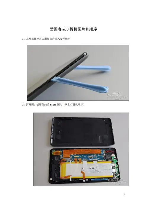
M4800 拆机图文解说讲课稿
- 格式:doc
- 大小:1.94 MB
- 文档页数:7

D e l l灵越I n s p i r o n M N官方拆机图解The latest revision on November 22, 2020戴尔Dell 灵越Inspiron M4040/14-N4050官方拆机图解取出电池1.按照开始之前中的说明进行操作。
2.关闭计算机并将其翻转。
3.将电池锁定闩锁滑至解除锁定位置,直至其卡入到位。
4.将电池释放闩锁滑至解除锁定位置,并按住电池释放闩锁。
5.滑动电池,并将其提离电池槽。
卸下键盘1.按照开始之前中的说明进行操作。
2.取出电池。
请参阅取出电池。
警告:键盘的键帽容易损坏和脱落,装回它们也比较费时。
卸下和处理键盘时,请小心操作。
3.翻转计算机并把显示屏打开到最大程度。
4.使用塑料划片,释放将键盘固定至掌垫的四个卡舌,然后轻轻地向上摇动键盘,直至其脱离掌垫。
警告:板。
7.将键盘提离计算机。
卸下内存模块1.按照开始之前中的说明进行操作。
2.取出电池。
请参阅取出电池。
3.卸下键盘。
请参阅卸下键盘。
警告:为避免损坏内存模块连接器,请勿使用工具来拨开内存模块固定夹。
4.请用指尖小心拨开内存模块连接器两端的固定夹,直至模块弹起。
5.从内存模块连接器中卸下内存模块。
卸下光盘驱动器1.按照开始之前中的说明进行操作。
2.取出电池。
请参阅取出电池。
3.卸下键盘。
请参阅卸下键盘。
4.拧下将光盘驱动器固定至计算机基座的螺钉。
5.使用塑料划片,推动光盘驱动器上的槽口,以将其从光盘驱动器卡盒中释放。
6.将光盘驱动器滑出光盘驱动器卡盒。
卸下掌垫部件1.按照开始之前中的说明进行操作。
2.取出电池。
请参阅取出电池。
3.拧下将掌垫部件固定至计算机基座的八颗螺钉。
4.卸下键盘。
请参阅卸下键盘。
5.拧下掌垫部件上的三颗螺钉。
警告:拉动连接器顶部的塑料卡舌,以避免损坏连接器。
锁,然后拔下电缆。
警告:中取出。
8.将掌垫部件提离计算机基座。
卸下电源按钮板1.按照开始之前中的说明进行操作。
2.取出电池。
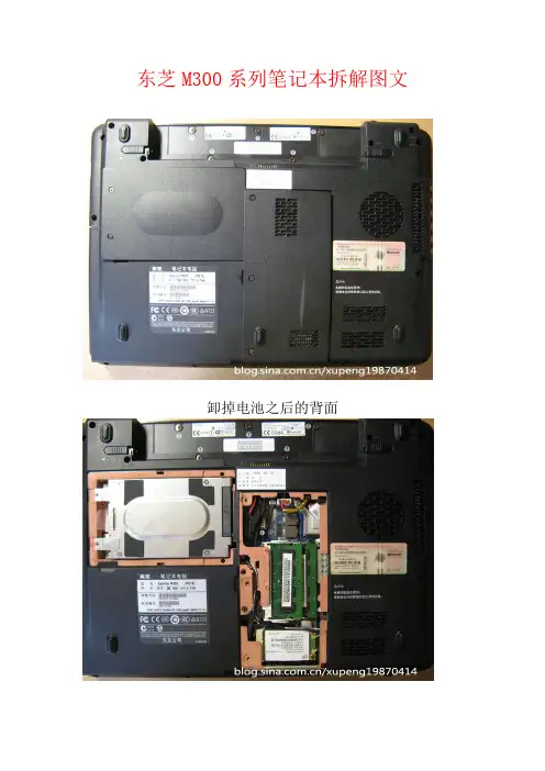
东芝M300系列笔记本拆解图文卸掉电池之后的背面第一步,卸掉硬盘保护盖的三颗螺丝和内存保护盖的三颗螺丝第二步,取下硬盘(向外侧平抽即能取下)东芝笔记本的硬盘第三步,取下底盖边框的螺丝,分别按照标号将螺丝分类放在一起,方便以后的安装.第四步,注意上方标号F4的螺丝,它是光驱的螺丝,将它拧下后,用螺丝刀向光驱一侧推一下,将光驱取出.东芝M319的光驱第五步,拔下下方图片中的红黑排线(注意:要轻轻地拔下)拔下无线网卡的两根天线(下方图片上另个金色的触控点)拔下下方图片光驱螺丝下方的黑色排线拔完排线的样子第五步,将笔记本电脑翻过来,准备拆卸键盘.注意那个键盘上方的黑色细条,取下的时候要轻轻翘,两边是有卡扣的,翘松之后将左边的部分向中间翘起,然后左边卡扣就取下了,再向左边抽动,右侧卡扣也即取下,整个装饰条就完好的取下了。
注意F1和INS按键上的两颗白色螺丝,这两颗螺丝是固定键盘的,将他们拧下。
拧下螺丝后将键盘向前拉动一下,翘起就可将键盘取下,注意不要直接将键盘拿起,因为背后有排线!!!上方图片最右边的螺丝也拧下。
键盘的排线注意下面那个黑色的夹子,将它向上提起之后,才能将键盘的排线取下之前卸下的几部分拆完键盘之后的面板部分第六步,准备拆下上面板拆下面板上所有标注箭头的螺丝,拆下来之后放在一起,拧下螺丝后,准备拆几处排线。
拆下上图中的四处排线,注意拆蓝色白线的时候要轻轻地弄(上面那个蓝色排线是触控板排线,下面那个是LED灯排线取下的上面板取下上面板之后剩下的部分第七步,取下主机板取下所有主机板上标有白色箭头的螺丝,主机板最左上角的一颗螺丝虽然没有标白色箭头,但也要取下注意下图的三颗螺丝,在取下主机板之前这三颗螺丝必须取下,接下来需要拆两处排线下图这根排线是USB及有线网卡的排线,只需将左侧一端取下即可下图这根排线是连接显示器的,需要取下HARMAN/KARDON音箱有线网卡,右侧USB部分取下主机板之后剩下的部分,这部分先拿到一边去了.拆下的主机板读卡器无线网卡内存条这是显卡,将显卡上的三颗螺丝取下将显卡取下ATI3470显卡将风扇右侧的三颗白色螺丝取下,取下散热器部分散热器部分P8400 CPU取下显卡和散热器部分的主机板,可以看到明显的灰尘.主板第八步,拆卸风扇将风扇上3颗黑色螺丝取下,将散热风扇取下来.清洗之后的风扇另外在GPU和CPU散热片上补填一些散热硅脂,散热效果会更好.注意拆卸的时候螺丝一定要标号分类摆放!!!(注:可编辑下载,若有不当之处,请指正,谢谢!)。
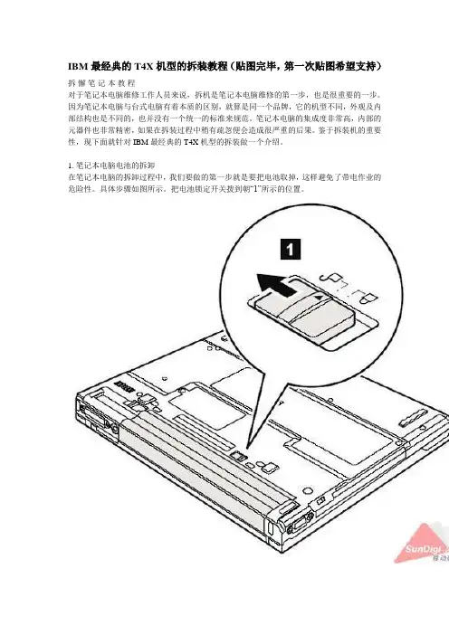
IBM最经典的T4X机型的拆装教程(贴图完毕,第一次贴图希望支持)拆懈笔记本教程对于笔记本电脑维修工作人员来说,拆机是笔记本电脑维修的第一步,也是很重要的一步。
因为笔记本电脑与台式电脑有着本质的区别,就算是同一个品牌,它的机型不同,外观及内部结构也是不同的,也并没有一个统一的标准来规范。
笔记本电脑的集成度非常高,内部的元器件也非常精密,如果在拆装过程中稍有疏忽便会造成很严重的后果。
鉴于拆装机的重要性,现下面就针对IBM最经典的T4X机型的拆装做一个介绍。
1. 笔记本电脑电池的拆卸在笔记本电脑的拆卸过程中,我们要做的第一步就是要把电池取掉,这样避免了带电作业的危险性。
具体步骤如图所示。
把电池锁定开关拨到朝“1”所示的位置。
按图所示把另一电池锁拨到“2”所示的方向,手握住电池朝“3”箭头所示方向拖出就可以了。
本文于2005-11-25 21:15:16.844被新好男孩修改过。
这是本帖的第2次修改。
2. 笔记本电脑光驱的拆卸如图所示,把小开关向“1”所示方向推去时光驱拖钩就会向“2”所示方向弹出,然后向弹出的方向拉伸即可。
本文于2005-11-25 21:19:15.757被新好男孩修改过。
这是本帖的第3次修改。
本文于2005-11-25 21:24:16.312被新好男孩修改过。
这是本帖的第4次修改。
如图所示,这时光驱已经出来一半了,拖住光驱的底部向“3”所示方向平行拖出即可本文于2005-11-25 21:27:25.568被新好男孩修改过。
这是本帖的第5次修改。
3. 笔记本电脑硬盘的拆卸如图所示,先取掉固定硬盘的螺丝如“1”所示。
如图所示,把笔记本电脑打开,成半开状态。
双手向“2”所示的方向拖出。
4. 笔记本电脑扩展内存的拆卸如图所示,打开内存盖螺丝“1”,拖起有螺丝的一端向“2”方向抬起即可。
如图所示,打开内存插槽盖后,把内存两边的卡子按照“3”所示方向分开。
按照“4”所示的方向取出内存。
5. 笔记本电脑键盘的拆卸如图所示,把图中“1”所示的4条螺丝拧掉。
IBM笔记本拆机图解仔细研究了一下R32、R40、T30的拆机手册,发现其结构与T23大同小异,只在细节部分有所不同,至于T20~22,与T23本是同根生,只有风扇主板CPU与T23不同,基本可完全借鉴本拆机过程。
对于R30、31,手头没有相应的拆机手册,不敢妄下结论,不过既然R32与T23结构相似,与R32同族的R30、31也应该差不多。
至于T40系列、R50系列与X系列,则在设计思路上与T23完全没有共同点。
A2x系列内置有软驱,A3x系列内置两个U2K,设计理念均与T23有较大差异,也不能借鉴。
首先搞定不需要工具就可以拆下的部分:电池和光驱:电池就不说了,T23的U2K光驱支持热插拔,不管你现在是开着机还是关着机,只要拨动光驱面板右下角的小开关就会跳出一个手柄,拉这个手柄,光驱就跟着出来了。
当然你要是想继续的话,还是把机器关了比较好T30、R3x、R40此步骤相同,对于R40e,由于没有弹出手柄,移除光驱需在卸下键盘之后进行然后把机器翻过来,拧下内存盖和网卡盖,分别由1颗螺丝固定。
拧下这两个盖子后,图片如下:为以后方便,将底部可见的螺丝全部编号如下。
注意,10、11、12三颗螺丝是藏在黑色塑料片底下的。
我是用缝衣针把塑料片挑起来然后粘到一卷两面胶上的。
R3x、R40、T30螺丝位置可能有不同,没拆过,对不起。
在此只能说可能不同,不能指出哪里不同,请原谅。
T20~22则只在CDC插槽部分有不同,在那里只有1颗螺丝固定键盘,而少了一颗螺丝固定掌托。
即只存在6号螺丝,不存在7号螺丝在以上步骤中,可以把两条内存先拿下来保存好。
至于miniPCI设备和CDC网卡暂且搁置不管。
键盘拧下5号、6号螺丝,注意6号螺丝是在CDC网卡上面的。
然后用手指顶电池接口下方的金属片(其实是鼠标键背面),从正面掀开键盘。
对于T30、R3x、R40,键盘是使用软线连接,与T2x不同。
先掀起键盘,再拔下软线。
硬盘用一枚1元硬币拧下8号螺丝,把上盖打开一个小角度,水平抽出硬盘2下一步是屏轴盖板拧下1号、2号螺丝,翻到正面,U2K盖板上方靠近屏轴处还有一颗螺丝固定屏轴盖板。
Dell Precision 移动工作站 M4800用户手册管制型号: P20E管制类型: P20E001版权所有© 2015 Dell Inc. 保留所有权利。
本产品受美国、国际版权和知识产权法律保护。
Dell™和 Dell 徽标是 Dell Inc. 在美国和/或其他司法管辖区的商标。
所有此处提及的其他商标和产品名称可能是其各自所属公司的商标。
2013 - 08Rev. A00目录1 拆装计算机 (6)拆装计算机内部组件之前 (6)建议工具 (7)关闭计算机电源 (7)拆装计算机内部组件之后 (8)2 卸下和安装组件 (9)系统概览 (9)内部视图—背面内部视图—正面 (9)卸下安全数字 (SD) 卡 (10)安装 SD 卡 (10)卸下 ExpressCard (11)安装 ExpressCard (11)取出电池 (11)安装电池 (12)卸下微型用户识别模块 (SIM) 卡 (12)安装微型用户识别模块 (SIM) 卡 (13)卸下键盘装饰条 (13)安装键盘装饰条 (13)卸下键盘 (14)安装键盘 (16)卸下基座盖 (17)安装基座盖 (19)卸下主内存 (19)安装主内存 (19)卸下次内存 (19)安装次内存 (20)卸下光盘驱动器 (20)安装光盘驱动器 (21)卸下硬盘驱动器 (22)安装硬盘驱动器 (23)卸下无线局域网 (WLAN) 卡 (23)安装无线局域网 (WLAN) 卡 (23)卸下无线广域网 (WWAN) 卡(可选) (23)安装无线广域网 (WWAN) 卡(可选) (24)卸下处理器风扇 (24)安装处理器风扇 (25)3卸下视频卡风扇 (25)安装视频卡风扇 (26)取出币形电池 (26)安装币形电池 (27)卸下掌垫 (27)安装掌垫 (29)卸下 ExpressCard 模块 (30)安装 ExpressCard 模块 (31)卸下处理器散热器 (32)安装处理器散热器 (32)卸下处理器 (33)安装处理器 (33)卸下视频卡散热器 (34)安装视频卡散热器 (35)卸下视频卡 (36)安装视频卡 (36)卸下输入/输出 (I/O) 板 (37)安装 I/O 板 (38)卸下开关板 (38)安装开关板 (39)卸下统一安全集线器 (USH) 板 (39)安装 USH 板 (40)卸下显示屏部件 (40)安装显示屏部件 (43)卸下铰接护盖 (43)安装铰接护盖 (44)卸下系统板 (44)安装系统板 (47)卸下电源连接器端口 (48)安装电源连接器端口 (49)卸下显示屏挡板 (49)安装显示屏挡板 (50)卸下显示屏面板 (51)安装显示屏面板 (54)卸下摄像头 (54)安装摄像头 (54)3 系统设置程序 (56)引导顺序 (56)导航键 (56)系统设置程序选项 (57)更新 BIOS (66)4系统密码和设置密码 (67)设定系统密码和设置密码 (67)删除或更改现有系统密码和/或设置密码 (68)4 Diagnostics(诊断程序) (69)增强型预引导系统评估 (ePSA) 诊断程序 (69)5 排除计算机故障 (70)设备状态指示灯 (70)电池状态指示灯 (70)技术规格 (71)6 联系 Dell (78)联系 Dell (78)51拆装计算机拆装计算机内部组件之前遵循以下安全原则有助于防止您的计算机受到潜在损坏,并有助于确保您的人身安全。
联想y485拆机图解联想y485拆机图解从市面的测试中可以看出,联想Y485-ATE在性能和易用性方面有让人满意的表现,但这远远是不够的,一款全面出色产品不但应该只有外在,在内部设计和做工也要让人满意。
那么对于联想Y485-ATE来说,其光鲜的外表背后其内部做工究竟如何呢?相信这是很多用户关心的话题。
下面我们就通过全面拆解,让大家看到联想Y485-ATE内部真实情况。
1.整体产品比较易于拆卸联想Y485-ATE在底盖的处理器区域虽然没有预留小盖板,但是整机的拆解并不显得复杂。
用户只需要拆掉底盖和电池仓内的所有螺丝(包括硬盘的固定螺丝),就能轻易取掉键盘和光驱。
接下来取掉光驱位的螺丝、键盘螺丝及键盘下方的连接线和一颗固定螺丝,就能轻易的分离C壳并看到内部主板和全部电路,整体步骤看似复杂,但是不需要太多的笔记本拆机经验,所以对于喜欢玩机的用户来说还是显得较为难得。
拆掉C壳后,Y485-ATE的内部做工规范,没有看到乱七八糟的景象。
内部做工规范工整,没有看到胶布等低劣的做工细节2.机身坚固度设计细节多通过拆机看到,Y485-ATE机身坚固度的相关设计不仅仅体现在顶盖和C 壳的金属材质上,其实还体现包括底盖以及机身内部的其他细节上。
Y485-ATE的光驱进行了加固设计,光驱位对应上下位置对应的C壳和底壳均用金属板进行了加固,这样可以确保光驱位的机身强度。
机身底部的大盖板下还带有一层较为完整的塑料框架进行加固,而不是直接裸露出主板,这样的设计看似多余,其实可以为整体带来更高的安全性,这种设计在目前主流中变得越来越少见了,而这也是这款机型相对偏重的.主要原因。
底壳的大盖板下方带有塑料骨架,可以为主板提供更好的保护光驱位对应的底壳和C壳区域均有金属加固板设计,可以确保整机的机身强度3.扬声器个头大Y485-ATE的扬声器效果出色,这和这款产品引入的JBL高端扬声器有着主要的关系。
但是这只是表现,通过拆解看到,Y485-ATE的扬声器单元体积很大,扬声器厚度几乎占据了机身尾部边角的大部分空间,扬声器的腔体大,这是这款机型输出功率大且音质出色的重要保证。
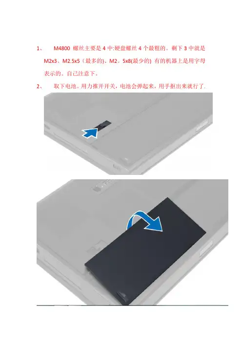
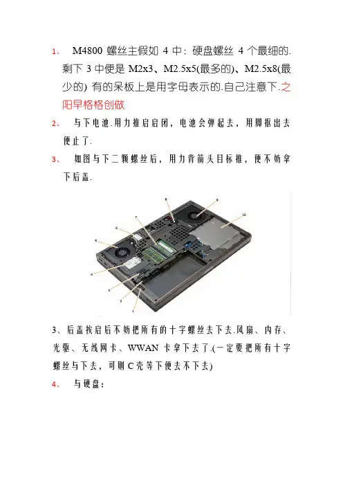
1、M4800 螺丝主要是4中:硬盘螺丝4个最粗的。
剩下3中就是
M2x3、M2.5x5(最多的)、M2。
5x8(最少的) 有的机器上是用字母表示的。
自己注意下。
2、取下电池。
用力推开开关,电池会弹起来,用手抠出来就行了.
3、如图取下两颗螺丝后,用力向箭头方向推,就可以拿下后盖。
3、后盖打开后可以把所有的十字螺丝去下来。
风扇、内存、光驱、无线网卡、WWAN卡拿下来了。
(一定要把所有十字螺丝取下来,不
然C壳等下就去不下来)
4、取硬盘:
5、取键盘框和键盘;
先把靠屏那边抬起来,再左右两边抬起来.(都是卡扣,没有螺丝的)
键盘框拿下来后,螺丝取掉。
从螺丝这边抬起来,键盘就只有左右两边卡扣了,下面有一条键盘连接线.(如下图)先把白色的卡扣轻轻打开,再拿出线.
6、取C壳(如图螺丝和连接线都取掉)注:带指纹的有两条线在电
池旁边要拿掉。
我取C壳是从两个圆孔的地方往上提的,大拇指伸进圆孔,剩下4指靠左右两边按着,大拇指往上抬。
装回去的时候要先把有两个缺口的外边装好对齐,再往下盖;
7、取CPU 和显卡:这两个都好取,打开螺丝就行了。
螺丝在散
热片上取不下来的,最好对角松开,锁的时候也是对角锁的。
锁CPU的时候一定要锁紧,转到底。
最后装机要注意的几个点:
1、CPU要锁紧;
2、插显卡和内存的时候,注意插好;
3、装好CPU和显卡散热片,插好内存,先点亮机器,再装其他
的壳。
(也可以先不装C壳,装好风扇,硬盘进系统用鲁大师测好温度,再装其他壳)。
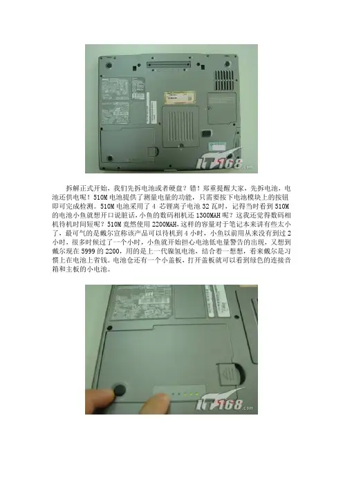
拆解正式开始,我们先拆电池或者硬盘?错!郑重提醒大家,先拆电池,电池还供电呢!510M电池提供了测量电量的功能,只需要按下电池模块上的按钮即可完成检测。
510M电池采用了4 芯锂离子电池32瓦时,记得当时看到510M 的电池小鱼就想开口说脏话,小鱼的数码相机还1300MAH呢?这我还觉得数码相机待机时间短呢?510M竟然使用2200MAH,这样的容量对于笔记本来讲有些太小了,最可气的是戴尔宣称该产品可以待机到4小时,小鱼以前用从来没有到过2小时,很多时候过了一个小时,小鱼就开始担心电池低电量警告的出现,又想到戴尔现在5999的2200,用的是上一代镍氢电池,结合着一想想,看来戴尔是习惯上在电池上省钱。
电池仓还有一个小盖板,打开盖板就可以看到绿色的连接音箱和主板的小电池。
DELL 510m的大部分模块都位于机器底部,其中包括了内存模块和硬盘,510M 配置韩国HYNIX PC2700 333MHZ 256MB DDR内存,分A、B内存插槽便于扩展。
硬盘是4200rpm 30GB的普通产品,与音频接口模块一体设计。
按压光驱旁边的按键,抓住按键,用力抽出光驱。
DELL 510m提供了无线模块,无线网卡带有黑白两条天线,直接通过穿行主板内部,上达液晶屏,起到更好的信号接收传送作用。
另外510M底部还有一个接口,是连接端口复制器或者扩展坞站使用的。
大家注意,小鱼在这里要插入对戴尔外壳的评价,大家还记得不久前小鱼拆解长城4999笔记本吗?小鱼认为长城4999外壳很差,又韧又薄。
小鱼对比着来,戴尔510MM的外壳也比较一般,但是比长城4999要强不少,外壳强度有一定提高,不过LCD外壳也有轻按出现凹陷的问题,电池拿出后,下面的隔离模具塑料也比较韧。
接下来小鱼开始深入拆解戴尔510M,我们先拆除键盘上的挡板,再此之前要做一件很简单但是很重要的事情,将510M背面,大大小小的不下20颗螺丝全部拆下。
有很多朋友抱怨拆机很难,尤其是螺丝的问题,经常拆卸安装完成后会多余几个螺丝,超级郁闷!对此小鱼提醒大家,一定要注意螺丝的规格和厂商给出的位置提示信息,例如戴尔510M整个电脑只有3种螺丝,直径2.5MM*长度8MM、直径2.5MM*长度5MM,直径2.5MM*长度3MM的3种螺丝,其中3MM螺丝用量很少重要是主板某些配件内固定,例如MODEM;5MM螺丝使用最多重要是内部配件固定,8MM螺丝主要是机器外围背面,一部分机器内部导热片固定。
1、M4800 螺丝主假如4中:硬盘螺丝4个最细的.
剩下3中便是M2x3、M2.5x5(最多的)、M2.5x8(最少的) 有的呆板上是用字母表示的.自己注意下.之阳早格格创做
2、与下电池.用力推启启闭,电池会弹起去,用脚抠出去便止了.
3、如图与下二颗螺丝后,用力背箭头目标推,便不妨拿下后盖.
3、后盖挨启后不妨把所有的十字螺丝去下去.风扇、内存、光驱、无线网卡、WWAN卡拿下去了.(一定要把所有十字螺丝与下去,可则C壳等下便去不下去)
4、与硬盘:
5、与键盘框战键盘;
先把靠屏那边抬起去,再安排二边抬起去.(皆是卡扣,不螺丝的)
键盘框拿下去后,螺丝与掉.从螺丝那边抬起去,键盘
便惟有安排二边卡扣了,底下有一条键盘连交线.(如下图)先把红色的卡扣沉沉挨启,再拿出线.
末尾拆秘密注意的几个面:
1、CPU要锁紧;
2、插隐卡战内存的时间,注意插佳;
3、拆佳CPU战隐卡集热片,插佳内存,先面明呆
板,再拆其余的壳.(也不妨先不拆C壳,拆佳风
扇,硬盘进系统用鲁大家测佳温度,再拆其余壳)。
Aspire 4810 Series Disassembly InstructionMachine Disassembly and ReplacementThis chapter contains step-by-step procedures on how to disassemble the notebook computer formaintenance and troubleshooting.Disassembly RequirementsTo disassemble the computer, you need the following tools:•Wrist grounding strap and conductive mat for preventing electrostatic discharge•Flat screwdriver•Philips screwdriver•Hex screwdriver•Plastic flat screwdriver•Plastic tweezersNOTE: The screws for the different components vary in size. During the disassembly process, group the screws with the corresponding components to avoid mismatch when putting back the components.23General InformationPre-disassembly InstructionsBefore proceeding with the disassembly procedure, make sure that you do the following:1.Turn off the power to the system and all peripherals.2.Unplug the AC adapter and all power and signal cables from the system.3.Place the system on a flat, stable surface.4.Remove any dummy card that might still be inside the card slot.Disassembly ProcessThe disassembly process is divided into the following stages:•External module disassembly •Main unit disassembly •LCD module disassemblyThe flowcharts provided in the succeeding disassembly sections illustrate the entire disassembly sequence. Observe the order of the sequence to avoid damage to any of the hardware components. For example, if you want to remove the main board, you must first remove the keyboard, then disassemble the inside assembly frame in that order. Main Screw ListItem ScrewColor Part No.A M2 x L4Black 86.00E13.524B M2 x L3Silver 86.9A522.3R0C M2.5 X L3.5Silver 86.9A563.3R5D M3 x L3Black 86.00E90.743E M2.5 x L6Black 86.00E12.536F M2.5 x L11Black 86.1A353.110G M2 x L2.5Silver 86.9A562.2R5H M2.5 x L5Black 86.00F87.735I M2 x L6Black 86.00K64.524JM2 x L3Black86.00K60.630External Module Disassembly ProcessItem Screw ColorB M2 x L3SilverD M3 x L3BlackF M2.5 x L11Black451.Turn base unit over.2.Slide the battery lock/unlock latch to the unlock position.3.Slide and hold the battery release latch to the release position.4.Then slide out the battery from the battery bay.Note: Battery has been highlighted with the red rectangle as above image shows. Please detach the61.See “Removing the Battery Pack” on page 5.2.Remove the two screws (F) and five captive screws securing the lower cover.e a plastic screw driver to carefully pry open the lower cover.4.Remove the lower cover from the lower case.StepSize (Quantity)Color Torque1~2M2.5 x L11 (2)Black3.0 kgf-cm7Removing the Optical Drive Module1.See “Removing the Battery Pack” on page 5.2.See “Removing the Lower Cover” on page 6.3.Use a screw driver and carefully push out and slide out the optical drive module out of the bay.4.Remove the one screw (B) securing the locker bracket and remove the locker bracket from the optical disk drive module.Removing the DIMM1.See “Removing the Battery Pack” on page 5.2.See “Removing the Lower Cover” on page 6.StepSize (Quantity)Color Torque1M2 x L3 (1)Silver1.6 kgf-cm83.Push out the latches on both sides of the DIMM socket to release the DIMM and remove it from the socket.4.Do the same to the other socket if there is any DIMM present.Removing the Hard Disk Drive Module1.See “Removing the Battery Pack” on page 5.2.See “Removing the Lower Cover” on page 6.3.Using the plastic tab, lift up the the hard disk drive module and remove it from the bay.NOTE:To prevent damage to device, avoid pressing down on it or placing heavy objects on top of it.94.Remove the two screws (D) securing the hard disk to the bracket and remove the hard disk from the bracket.Removing the SSD Module1.See “Removing the Battery Pack” on page 5.2.See “Removing the Lower Cover” on page 6.3.Using the plastic tab, slide the SSD module away from the connector and lift to remove it from the system.Removing the RTC Battery1.See “Removing the Battery Pack” on page 5.2.See “Removing the Lower Cover” on page 6.StepSize (Quantity)Color Torque1~2M3 x L3 (2)Black3.0 kgf-cm3.Disconnect the RTC battery cable from the system board and lift to remove it.NOTE: Be careful when removing the RTC battery. It is glued to the system board.Note: Battery has been highlighted with the red rectangle as above image shows. Please detach the10Main Unit Disassembly ProcessItem Screw ColorA M2 x L4BlackE M2.5 x L6BlackH M2.5 x L5BlackI M2 x L6BlackRemoving the Keyboard1.See “Removing the Battery Pack” on page 5.2.Release the keyboard from the latches securing it.3.Carefully pry loose the keyboard.4.Place the keyboard below the LCD screen to gain access to the keyboard cable.5.Disconnect the keyboard cable from the main board to remove the keyboard.Removing the WLAN Board Module1.See “Removing the Battery Pack” on page 5.2.See “Removing the Keyboard” on page 12.3.Disconnect the antenna cables from the WLAN board.NOTE: There are 2 antenna cables connected to the WLAN board. The Black antenna cable is connected to connector 1and the White antenna cable is connected to connector 2.4.Remove the one screw (A) on the WLAN board to release the WLAN board.5.Detach the WLAN board from the WLAN socket.NOTE: When attaching the antenna back to the WLAN board, make sure the cable are arranged properly.Separating the Upper Case from the Lower Case1.See “Removing the Battery Pack” on page 5.2.See “Removing the Lower Cover” on page 6.3.See “Removing the Lower Cover” on page 6.4.See “Removing the Optical Drive Module” on page 7.5.See “Removing the DIMM” on page 7.6.See “Removing the Hard Disk Drive Module” on page 8.7.See “Removing the SSD Module” on page 9.8.See “Removing the RTC Battery” on page9.9.See “Removing the Keyboard” on page 12.10.See “Removing the WLAN Board Module” on page 13.StepSize (Quantity)Color Torque1M2 x L4 (1)Black1.6 kgf-cm11.Remove the twelve screws (I, E, H) from the bottom panel.12.Disconnect the touchpad cable from the TPAD1 connector on the main board.13.Disconnect the function key board cable from the MMB1 connector on the system board.StepSize (Quantity)Color Torque1~2M2.5 x L6 (2)Black 3.0 kgf-cm 3~4M2 x L4 (2)Black 3.0 kgf-cm 5~12M2.5 x L5 (8)Black3.0 kgf-cm14.Disconnect the power button cable from the BTB2 connector on the system board.15.Disconnect the speaker cable from the SPK1 connector on the system board.16.Gently separate the upper case from the lower case.Removing the Power Button Board1.See “Removing the Battery Pack” on page 5.2.See “Removing the Lower Cover” on page 6.3.See “Removing the Lower Cover” on page 6.4.See “Removing the Optical Drive Module” on page 7.5.See “Removing the DIMM” on page 7.6.See “Removing the Hard Disk Drive Module” on page 8.7.See “Removing the SSD Module” on page 9.8.See “Removing the RTC Battery” on page 9.9.See “Removing the Keyboard” on page 12.10.See “Removing the WLAN Board Module” on page 13.11.See “Separating the Upper Case from the Lower Case” on page 14.12.Release the power button board from that latches and remove from the upper case.Removing the Touchpad Module1.See “Removing the Battery Pack” on page 5.2.See “Removing the Lower Cover” on page 6.3.See “Removing the Lower Cover” on page 6.4.See “Removing the Optical Drive Module” on page 7.5.See “Removing the DIMM” on page 7.6.See “Removing the Hard Disk Drive Module” on page 8.7.See “Removing the SSD Module” on page 9.8.See “Removing the RTC Battery” on page 9.9.See “Removing the Keyboard” on page 12.10.See “Removing the WLAN Board Module” on page 13.11.See “Separating the Upper Case from the Lower Case” on page 14.12.Disconnect the touchpad cable from the touchpad board; then carefully pry loose and remove the touchpad boardWARNING:The touchpad board is glued to the upper case, only remove the touchpad board if it is defective.Circuit board > 10cm2 has been highlighted with the red rectangle as shown in the figureRemoving the Speaker Module1.See “Removing the Battery Pack” on page 5.2.See “Removing the Lower Cover” on page 6.3.See “Removing the Lower Cover” on page 6.4.See “Removing the Optical Drive Module” on page 7.5.See “Removing the DIMM” on page 7.6.See “Removing the Hard Disk Drive Module” on page 8.7.See “Removing the SSD Module” on page 9.8.See “Removing the RTC Battery” on page 9.9.See “Removing the Keyboard” on page 12.10.See “Removing the WLAN Board Module” on page 13.11.See “Separating the Upper Case from the Lower Case” on page 14.12.Remove the two screws (A) securing the left and right speaker modules, peel off the stickers securing thespeaker cables, and remove them from the upper case.Removing the LED Board1.See “Removing the Battery Pack” on page 5.2.See “Removing the Lower Cover” on page 6.3.See “Removing the Lower Cover” on page 6.4.See “Removing the Optical Drive Module” on page 7.5.See “Removing the DIMM” on page 7.6.See “Removing the Hard Disk Drive Module” on page 8.7.See “Removing the SSD Module” on page 9.8.See “Removing the RTC Battery” on page9.9.See “Removing the Keyboard” on page 12.10.See “Removing the WLAN Board Module” on page 13.11.See “Separating the Upper Case from the Lower Case” on page 14.12.Peel off the covering of the LED board.StepSize (Quantity)Color Torque1~2M2 x L4 (2)Black1.6 kgf-cm13.Carefully pry loose and remove the LED board from the upper case.WARNING:The LED board is glued to the upper case, only remove the LED board if it is defective. Removing the LCD Module1.See “Removing the Battery Pack” on page 5.2.See “Removing the Lower Cover” on page 6.3.See “Removing the Lower Cover” on page 6.4.See “Removing the Optical Drive Module” on page 7.5.See “Removing the DIMM” on page 7.6.See “Removing the Hard Disk Drive Module” on page 8.7.See “Removing the SSD Module” on page 9.8.See “Removing the RTC Battery” on page 9.9.See “Removing the Keyboard” on page 12.10.See “Removing the WLAN Board Module” on page 13.11.See “Separating the Upper Case from the Lower Case” on page 14.12.Release the wireless antenna cables from the latches.13.Disconnect the LCD cable.14.Pell off the LCD cable from the fan.15.Remove the two screws (E) from the left and right hinge of the LCD module.Step Size (Quantity)Color Torque 1~2M2.5 x L6 (2)Black 3.0 kgf-cm16.Carefully remove the LCD module from the base unit.NOTE: When connecting the cables back to the unit, please note that the cables should be routed well. Removing the System Board1.See “Removing the Battery Pack” on page 5.2.See “Removing the Lower Cover” on page 6.3.See “Removing the Lower Cover” on page 6.4.See “Removing the Optical Drive Module” on page 7.5.See “Removing the DIMM” on page 7.6.See “Removing the Hard Disk Drive Module” on page 8.7.See “Removing the SSD Module” on page 9.8.See “Removing the RTC Battery” on page 9.9.See “Removing the Keyboard” on page 12.10.See “Removing the WLAN Board Module” on page 13.11.See “Separating the Upper Case from the Lower Case” on page 14.12.See “Removing the LCD Module” on page 20.13.Disconnect the card reader board cable from the system board.14.Disconnect the top daughter board cable from the system board.15.Disconnect the bottom system board cable from the daughter board.16.Remove the one screw (A) securing the system board and the mini board..Step Size (Quantity)Color Torque 1M2 x L4 (1)Black 1.6 kgf-cm17.Carefully remove the main board.Removing the Thermal Module1.See “Removing the Battery Pack” on page 5.2.See “Removing the Lower Cover” on page 6.3.See “Removing the Lower Cover” on page 6.4.See “Removing the Optical Drive Module” on page 7.5.See “Removing the DIMM” on page 7.6.See “Removing the Hard Disk Drive Module” on page 8.7.See “Removing the SSD Module” on page 9.8.See “Removing the RTC Battery” on page 9.9.See “Removing the Keyboard” on page 12.10.See “Removing the WLAN Board Module” on page 13.11.See “Separating the Upper Case from the Lower Case” on page 14.12.See “Removing the System Board” on page 22.13.Disconnect the thermal module cable from the system board.14.Turn over the system board and loosen the four captive screws securing the thermal module.15.Carefully remove the heatsink module from the system.Removing the Mini Board Module1.See “Removing the Battery Pack” on page 5.2.See “Removing the Lower Cover” on page 6.3.See “Removing the Lower Cover” on page 6.4.See “Removing the Optical Drive Module” on page 7.5.See “Removing the DIMM” on page 7.6.See “Removing the Hard Disk Drive Module” on page 8.7.See “Removing the SSD Module” on page 9.8.See “Removing the RTC Battery” on page 9.9.See “Removing the Keyboard” on page 12.10.See “Removing the WLAN Board Module” on page 13.11.See “Separating the Upper Case from the Lower Case” on page 14.12.See “Removing the System Board” on page 22.13.Remove the one screw (A) securing the mini board to the system board.14.Detach the system board from the mini board.Circuit boards > 10cm 2 has been highlighted with the red rectangle as shown in the figureRemoving the Daughter Board Module1.See “Removing the Battery Pack” on page 5.2.See “Removing the Lower Cover” on page 6.3.See “Removing the Lower Cover” on page 6.4.See “Removing the Optical Drive Module” on page 7.5.See “Removing the DIMM” on page 7.6.See “Removing the Hard Disk Drive Module” on page 8.7.See “Removing the SSD Module” on page 9.8.See “Removing the RTC Battery” on page 9.9.See “Removing the Keyboard” on page 12.10.See “Removing the WLAN Board Module” on page 13.11.See “Separating the Upper Case from the Lower Case” on page 14.StepSize (Quantity)Color Torque 1M2 x L4 (1)Black 1.6 kgf-cm12.See “Removing the System Board” on page 22.13.Release the daughter board from the latch.14.Carefully lift the daughter board and remove it from the lower case.Circuit board > 10cm2 has been highlighted with the red rectangle as shown in the figureRemoving the Card Reader Board1.See “Removing the Battery Pack” on page 5.2.See “Removing the Lower Cover” on page 6.3.See “Removing the Lower Cover” on page 6.4.See “Removing the Optical Drive Module” on page 7.5.See “Removing the DIMM” on page 7.6.See “Removing the Hard Disk Drive Module” on page 8.7.See “Removing the SSD Module” on page 9.8.See “Removing the RTC Battery” on page 9.9.See “Removing the Keyboard” on page 12.10.See “Removing the WLAN Board Module” on page 13.11.See “Separating the Upper Case from the Lower Case” on page 14.12.See “Removing the System Board” on page 22.13.Remove the one screw (A) securing the card reader board to the lower case.14.Remove the card reader board from the lower case.Circuit board > 10cm 2 has been highlighted with the red rectangle as shown in the figureRemoving the Bluetooth Module1.See “Removing the Battery Pack” on page 5.2.See “Removing the Lower Cover” on page 6.3.See “Removing the Lower Cover” on page 6.4.See “Removing the Optical Drive Module” on page 7.5.See “Removing the DIMM” on page 7.6.See “Removing the Hard Disk Drive Module” on page 8.7.See “Removing the SSD Module” on page 9.8.See “Removing the RTC Battery” on page 9.9.See “Removing the Keyboard” on page 12.10.See “Removing the WLAN Board Module” on page 13.11.See “Separating the Upper Case from the Lower Case” on page 14.StepSize (Quantity)Color Torque 1M2 x L4 (1)Black 1.6 kgf-cm12.See “Removing the Card Reader Board” on page 27.13.Disconnect the Bluetooth module cable from the bottom of the card reader board.14.Carefully pry loose and remove the Bluetooth module from the card reader board.WARNING:The Bluetooth module is glued to the card reader board, only remove the Bluetooth module if it is defective.Removing the Touchpad Lock Board1.See “Removing the Battery Pack” on page 5.2.See “Removing the Lower Cover” on page 6.3.See “Removing the Lower Cover” on page 6.4.See “Removing the Optical Drive Module” on page 7.5.See “Removing the DIMM” on page 7.6.See “Removing the Hard Disk Drive Module” on page 8.7.See “Removing the SSD Module” on page 9.8.See “Removing the RTC Battery” on page 9.9.See “Removing the Keyboard” on page 12.10.See “Removing the WLAN Board Module” on page 13.11.See “Separating the Upper Case from the Lower Case” on page 14.12.Carefully pry loose and remove the touchpad lock board from the lower case.WARNING:The touchpad lock board is glued to the lower case, only remove the touchpad lock board if it is defective.LCD Module Disassembly ProcessItem Screw ColorC M2.5 X L3.5SilverG M2 x L2.5SilverJ M2 x L3BlackRemoving the LCD Bezel1.See “Removing the Battery Pack” on page 5.2.See “Removing the Lower Cover” on page 6.3.See “Removing the Lower Cover” on page 6.4.See “Removing the Optical Drive Module” on page 7.5.See “Removing the DIMM” on page 7.6.See “Removing the Hard Disk Drive Module” on page 8.7.See “Removing the SSD Module” on page 9.8.See “Removing the RTC Battery” on page 9.9.See “Removing the Keyboard” on page 12.10.See “Removing the WLAN Board Module” on page 13.11.See “Separating the Upper Case from the Lower Case” on page 14.12.See “Removing the LCD Module” on page 20.13.Remove the four rubber screw covers from the LCD bezel.14.Remove the four screws (C) on the LCD module as shown.Step Size (Quantity)Color Torque 1~4M2.5 x L3.5 (4)Silver 3.0 kgf-cm15. Carefully pry open the LCD bezel and and remove the bezel from the LCD panel.Removing the LCD Panel1.See “Removing the Battery Pack” on page 5.2.See “Removing the Lower Cover” on page 6.3.See “Removing the Lower Cover” on page 6.4.See “Removing the Optical Drive Module” on page 7.5.See “Removing the DIMM” on page 7.6.See “Removing the Hard Disk Drive Module” on page 8.7.See “Removing the SSD Module” on page 9.8.See “Removing the RTC Battery” on page 9.9.See “Removing the Keyboard” on page 12.10.See “Removing the WLAN Board Module” on page 13.11.See “Separating the Upper Case from the Lower Case” on page 14.12.See “Removing the LCD Module” on page 20.13.See “Removing the LCD Bezel” on page 32.14.See “Removing the LCD Panel Hinges” on page 35.15.Remove the four screws (G) securing the LCD panel to the back cover.16.Carefully lift up the LCD panel and turn it over to gain access to the LCD cable.17.Detach the acetic tape on the LCD cable.Step Size (Quantity)Color Torque 1~4M2 x L2.5 (4)Silver1.6 kgf-cm18.Detach the LCD cable from the LCD panel.19.Remove the LCD panel from the back cover.Removing the LCD Panel Hinges1.See “Removing the Battery Pack” on page 5.2.See “Removing the Lower Cover” on page 6.3.See “Removing the Lower Cover” on page 6.4.See “Removing the Optical Drive Module” on page 7.5.See “Removing the DIMM” on page 7.6.See “Removing the Hard Disk Drive Module” on page 8.7.See “Removing the SSD Module” on page 9.8.See “Removing the RTC Battery” on page 9.9.See “Removing the Keyboard” on page 12.10.See “Removing the WLAN Board Module” on page 13.11.See “Separating the Upper Case from the Lower Case” on page 14.12.See “Removing the LCD Module” on page 20.13.See “Removing the LCD Bezel” on page 32.14.Remove the hinge caps on both side of the hinges.15.Remove the four screws (J) securing the left and right hinges, and remove the hingesRemoving the Webcam1.See “Removing the Battery Pack” on page 5.2.See “Removing the Lower Cover” on page 6.3.See “Removing the Lower Cover” on page 6.4.See “Removing the Optical Drive Module” on page 7.5.See “Removing the DIMM” on page 7.6.See “Removing the Hard Disk Drive Module” on page 8.7.See “Removing the SSD Module” on page 9.8.See “Removing the RTC Battery” on page 9.9.See “Removing the Keyboard” on page 12.10.See “Removing the WLAN Board Module” on page 13.11.See “Separating the Upper Case from the Lower Case” on page 14.12.See “Removing the LCD Module” on page 20.13.See “Removing the LCD Bezel” on page 32.Step Size (Quantity)Color Torque 1~4M2.5 x L2.5 (4)Black1.6 kgf-cm14.Disconnect the cable from the webcam.15.Carefully pry loose the webcam.CAUTION: Only remove the webcam if it is defective as it is glued to the back cover. Removing the Microphone1.See “Removing the Battery Pack” on page 5.2.See “Removing the Lower Cover” on page 6.3.See “Removing the Lower Cover” on page 6.4.See “Removing the Optical Drive Module” on page 7.5.See “Removing the DIMM” on page 7.6.See “Removing the Hard Disk Drive Module” on page 8.7.See “Removing the SSD Module” on page 9.8.See “Removing the RTC Battery” on page 9.9.See “Removing the Keyboard” on page 12.10.See “Removing the WLAN Board Module” on page 13.11.See “Separating the Upper Case from the Lower Case” on page 14.12.See “Removing the LCD Module” on page 20.13.See “Removing the LCD Bezel” on page 32.14.Disconnect the cable from the microphone, then remove the microphone.。
DELLM拆机图解教程————————————————————————————————作者:————————————————————————————————日期:拆机前准备:切断电源取下电池必要的工具步骤一:取下电池步骤二:取出内存条取出内存示范取出散热器示范分段一:拆解键盘步骤一:先卸下背部电池处固定键盘螺丝步骤二:卸下XPS LOGO附近的固定金属框步骤三:轻轻拗起触摸键条框蓝牙模块位置步骤四:卸下键盘上方的两颗固定螺丝4、keyboard cable 键盘排线5、plastic securing bar 塑料材质的安全条1、cable release tabs2、center control cover cable 分段二:无线网卡拆卸步骤一:卸下固定螺丝步骤二:拔去连线文章笔记本笔记本型号搜 索• 首页 • 行情 • 导购 • 新品 • 新闻 • 应用 • 评测 •周边•壁纸•驱动•产品库•本本论坛本本网> 评测> 欧美品牌> 正文戴尔M1330官方拆解教程图文演示本本网日期:2008/05/26 作者:taotao 来源:本本网进入论坛[团购]瑞士军刀威戈双肩笔记本背包快来抢哦!分段三:拆解显示屏拆解前最好取下无线网卡、内存、硬盘等步骤一:取下背部电池两侧的固定螺丝步骤二:拆解键盘,详见上页键盘拆解步骤三:取下键盘两侧固定螺丝笔记本型号搜 索•首页•行情•导购•新品•新闻•应用•评测•周边•壁纸•驱动•产品库•本本论坛本本网> 评测> 欧美品牌> 正文戴尔M1330官方拆解教程图文演示本本网日期:2008/05/26 作者:taotao 来源:本本网进入论坛[团购]瑞士军刀威戈双肩笔记本背包快来抢哦!摄像头笔记本型号搜 索•首页•行情•导购•新品•新闻•应用•评测•周边•壁纸•驱动•产品库•本本论坛本本网> 评测> 欧美品牌> 正文戴尔M1330官方拆解教程图文演示本本网日期:2008/05/26 作者:taotao 来源:本本网进入论坛[团购]瑞士军刀威戈双肩笔记本背包快来抢哦!分段四:零件拆解光驱拆卸读卡器拆卸1、喇叭连接器2、按键连接器3、松开按键的排线。
本文由gsyl0888贡献doc文档可能在WAP端浏览体验不佳。
建议您优先选择TXT,或下载源文件到本机查看。
拆解 IBM 笔记本操作手册对于笔记本电脑维修工作人员来说,拆机是笔记本电脑维修的第一步,也是很重要的一步。
因为笔记本电脑与台式电脑有着本质的区别,就算是同一个品牌,它的机型不同,外观及内部结构也是不同的,也并没有一个统一的标准来规范。
笔记本电脑的集成度非常高,内部的元器件也非常精密,如果在拆装过程中稍有疏忽便会造成很严重的后果。
鉴于拆装机的重要性,我们下面就针对 IBM 最经典的 T40 系列机型的拆装做一个介绍。
1. 笔记本电脑电池的拆卸在笔记本电脑的拆卸过程中,我们要做的第一步就是要把电池取掉,这样避免了带电作业的危险性。
具体步骤如图所示。
把电池锁定开关拨到朝“1”所示的位置。
按图所示把另一电池锁拨到“2”所示的方向,手握住电池朝“3”箭头所示方向拖出就可以了2.笔记本电脑光驱的拆卸如图所示,把小开关向“1”所示方向推去时光驱拖钩就会向“2”所示方向弹出,然后向弹出的方向拉伸即可。
如图所示,这时光驱已经出来一半了,拖住光驱的底部向“3”所示方向平行拖出即可 3.笔记本电脑硬盘的拆卸如图所示,先取掉固定硬盘的螺丝如“1”所示如图所示,把笔记本电脑打开,成半开状态。
双手向“2”所示的方向拖出4.笔记本电脑扩展内存的拆卸如图所示,打开内存盖螺丝“1”,拖起有螺丝的一端向“2”方向抬起即可。
如图所示,打开内存插槽盖后,把内存两边的卡子按照“3”所示方向分开。
按照“4”所示的方向取出内存 5. 笔记本电脑键盘的拆卸如图所示,把图中“1”所示的 4 条螺丝拧掉如图所示,按照“2”所示的方向向前推键盘即可,使键盘松落。
如图所示,键盘这时可以取下,但要注意键盘与主板的连线。
用力不要过大以免损坏键盘线,按照“1”所示的方向拔出接口即可。
6.笔记本内置内存的拆卸如图所示,取下键盘后你会看到键盘下有一条内存,这时按照“1”、“2”所示的方向取下内存即可。
联想B480拆机教程
时间:2021.03.05 创作:欧阳理
1、准备螺丝刀、刷子等工具。
2、笔记本背面,把电池卸了,把如下图红圈位置的两颗螺丝卸掉。
3、卸掉螺丝以后,滑动后盖,可以轻松取下来,然后把如下图红圈位置的螺丝卸掉。
4、卸掉硬盘的螺丝,然后抽动硬盘尾部的黑色胶带,轻轻把硬盘拉出来。
5、卸掉光驱的螺丝,拔出光驱。
6、拔出光驱后,光驱挡住的三颗小螺丝也露出来,一一拆下。
7、把连接无线网卡的两根线抠出来。
8、接下来转到正面,键盘部分,键盘上部分共有 4个卡口,用一字螺丝刀反方向,轻轻的将键盘卡口逐一翘起。
9、轻轻翘起键盘,注意键盘排线,把排线接头那个黑色的卡子轻轻拉开(不是拔出,而是往上拉成90°),取出键盘排线。
10、把如下红圆圈排线接头那个黑色的卡子轻轻拉开(不是拔出,而是往上拉成90°),取出排线。
11、把如下图红圈位置的螺丝卸掉。
12、接下来就拆C面的面板了。
拆的时候注意,按下图画红线的缝用一字螺丝刀轻轻顶出来,使其翘起,然后用指甲或卡片从正前方向屏幕依次把C面翘起,然后把C面往正前方拉出。
13、按下图操作(拔出三组电源线,拉开三个卡子)。
14、把如下图红圈位置的螺丝卸掉,卸掉后就可以取出主板。
15、把如下图红圈位置的螺丝松开,就可以卸下散热模组。
16、卸下散热模组,就看到了处理器和显卡,小的是处理器,大的是显卡。
17、好了,联系B480笔记本的拆机教程到此结束,大家可以清灰或者改造了,之后按照步骤重新再安装就可以了。
M4800拆机图文解说
1、M4800 螺丝主要是4中:硬盘螺丝4个最粗的。
剩下3中就
是M2x3、M2.5x5(最多的)、M2.5x8(最少的) 有的机器上是用字母表示的。
自己注意下。
2、取下电池。
用力推开开关,电池会弹起来,用手抠出来就行
了。
3、如图取下两颗螺丝后,用力向箭头方向推,就可以拿下后盖。
3、后盖打开后可以把所有的十字螺丝去下来。
风扇、内存、光驱、
无线网卡、WWAN卡拿下来了。
(一定要把所有十字螺丝取下来,不然C壳等下就去不下来)
4、取硬盘:
5、取键盘框和键盘;
先把靠屏那边抬起来,再左右两边抬起来。
(都是卡扣,没有螺丝的)
键盘框拿下来后,螺丝取掉。
从螺丝这边抬起来,键盘就只有左右两边卡扣了,下面有一条键盘连接线。
(如下图)先把白色的卡扣轻轻打开,再拿出线。
6、取C壳(如图螺丝和连接线都取掉) 注:带指纹的有两条线在电
池旁边要拿掉。
我取C壳是从两个圆孔的地方往上提的,大拇指伸进圆孔,剩下4指靠左右两边按着,大拇指往上抬。
装回去的时候要先把有两个缺口的外边装好对齐,再往下盖;
7、取CPU 和显卡:这两个都好取,打开螺丝就行了。
螺丝在散
热片上取不下来的,最好对角松开,锁的时候也是对角锁的。
锁CPU的时候一定要锁紧,转到底。
最后装机要注意的几个点:
1、CPU要锁紧;
2、插显卡和内存的时候,注意插好;
3、装好CPU和显卡散热片,插好内存,先点亮机器,再装
其他的壳。
(也可以先不装C壳,装好风扇,硬盘进系统用鲁大师测好温度,再装其他壳)。