CPM1300安装手册
- 格式:pdf
- 大小:1.19 MB
- 文档页数:10

迅达A P M M R现场安装手册SANY标准化小组 #QS8QHH-HHGX8Q8-GNHHJ8-HHMHGN#安装缩略图摘要本手册提供了在亚太区范围内使用脚手架安装300P MMR主要安装步骤的详细说明。
本手册为保密文件,并仅供授权的培训人员使用。
目录1 安全建议 (4)概要 (4)使用符号 (4)2 先决条件 (5)产品概述 (5)安装步骤 (7)专用工具 (9)3 施工现场准备工作 (10)4 导轨安装 (15)准备工作 (15)导轨支架安装 (15)导轨安装 (21)导轨基座 (21)导轨安装 (22)连接板校正 (24)5 Varidor 30AP C2 厅门入口安装 (25)门框预安装 (27)地坎支架 (30)门框和机械横梁 (31)地坎和护脚板 (35)门板 (36)C2井道互锁装置 (40)门解锁装置 (41)安装门重锤 (42)防护罩 (44)6 PMS420无齿轮机组安装 (45)机组支架 (47)安装PMS420无齿轮机组 (48)*手动应急操作选配装置 (51)制动器调整和制动力测试 (57)*曳引钢丝绳悬挂装置安装 (58)*安装限速器 (62)7 *安装GGM2-AP对重 (71)先决条件 (71)*机械安装 (72)*缓冲器支撑 (72)*对重校正 (73)*安全钳(选配) (74)*导靴 (76)油杯(选配) (79)*对重块 (79)*补偿链悬挂装置 (80)地震传感器(选配) (81)*调整和最后检查 (82)对重防护屏 (83)*对重防护屏后置 (83)*对重防护屏侧置 (84)8 安装轿厢架FRS9-AP/FRM9-AP (87)安装轿厢架FRS9-AP (87)FRS9-AP安全钳和导靴选配件 (98)FRM9-AP安全钳和导靴选配件 (99)9 安装曳引绳 (100)处理钢丝绳 (100)安装钢丝绳 (101)钢丝绳绳头安装 (105)检查钢丝绳张紧度和绳的润滑 (109)限速器钢丝绳 (110)10 轿厢P9KD-AP(CM)安装 (117)轿厢安装步骤 (118)*安装轿厢装璜 (134)安装满载、超载开关 (143)轿厢平衡装置 (144)11 V30 AP轿门安装 (145)11.1 C2轿门 (145)11.1.1 轿门机驱动 (146)11.1.2 轿门板 (147)11.1.3 轿门刀 (149)安装光幕(MiniMax光幕LVH) (151)12 安装缓冲器 (157)13 安装补偿链 (159)补偿链导向装置 (159)4-滚轮导靴 (159)2-滚轮导靴 (162)补偿链 (165)14 安装MX-GC (170)先决条件 (170)材料范围 (171)控制柜 (172)井道信息 (174)井道信息IGSI (174)绝对值线型井道信息系统 (190)控制柜内模块 (210)机房电缆 (211)井道电缆 (215)准备 (220)安装 (223)调整和最后检查 (229)OKR (231)随行电缆 (236)带IGSI和LONCIB的MX-GC,HQ<=70m (237)带IGSI和LONCIB的MX-GC,HQ>70m (238)带IGSI和LONIC/LONICK的MX-GC,HQ<=70m (239)带IGSI和LONIC/LONICK的MX-GC,HQ>70m (240)控制柜内的概述与名称 (241)15 VARIODYN VF44BR和VF88BR安装 (243)VARIODYN VF44BR安装 (243)VARIODYN VF88BR安装 (249)1 安全建议概要安全要求所有参与的安装人员必须熟悉并遵守公司以及当地的安全规范,特别要注意以下几点:照明必须充足,以保证安全生产。
Ordering GuideCisco Aironet 1300 Series Outdoor Access Point or BridgeThe Cisco® Aironet® 1300 Series Outdoor Access Point or Bridge is available with the following choices:●Operating autonomously or with a Cisco wireless LAN controller as part of a unified architecture●With a 13-dBi integrated antenna or with RP-TNC connectors for an externally attached antenna●For the FCC, ETSI, or TELEC regulatory domainsTwelve versions are available for different combinations of these options:●Cisco Aironet 1310 Outdoor Access Point/Bridge with 13-dBi integrated antenna, FCC config●Cisco Aironet 1310 Outdoor Access Point/Bridge with 13-dBi integrated antenna, ETSI config●Cisco Aironet 1310 Outdoor Access Point/Bridge with 13-dBi integrated antenna, TELEC config●Cisco Aironet 1310 Outdoor Access Point/Bridge with RP-TNC type Connectors, FCC config●Cisco Aironet 1310 Outdoor Access Point/Bridge with RP-TNC type Connectors, ETSI config●Cisco Aironet 1310 Outdoor Access Point/Bridge with RP-TNC type Connectors, TELEC config●Cisco Aironet 1310 LWAPP Outdoor Access Point with 13-dBi integrated antenna, FCC config●Cisco Aironet 1310 LWAPP Outdoor Access Point with 13-dBi integrated antenna, ETSI config●Cisco Aironet 1310 LWAPP Outdoor Access Point with 13-dBi integrated antenna, TELEC config●Cisco Aironet 1310 LWAPP Outdoor Access Point with RP-TNC type connectors, FCC config●Cisco Aironet 1310 LWAPP Outdoor Access Point with RP-TNC type connectors, ETSI config●Cisco Aironet 1310 LWAPP Outdoor Access Point with RP-TNC type connectors, TELEC configA Cisco Aironet 1300 Series device operating autonomously is an intelligent access point or bridge, capable of functioning as a standalone device. As an LWAPP access point, the Cisco Aironet 1300 Series works along with the Cisco wireless LAN controller to enable centralized configuration and management, application of security policies, and seamless mobility. When operating with wireless LAN controllers, Cisco Aironet 1300 Series Outdoor Access Points/Bridges function only as access points and are not capable of bridging.The integrated antenna versions feature a radio and high-gain patch antenna for user installations of either point-to-point links or non-root nodes of point-to-multipoint networks. The connectorized versions provide professional installers with RP-TNC type connectors that allow the deployment of nodes with omnidirectional, sector, or high-gain dish antennas for longer links. In all cases, the mounting kit must be ordered separately.All parts, along with accessories such as the Roof Mount Kit, Wall Mount Kit, cable, antennas, and power supplies, are available on the Cisco Systems® global and wholesale price lists.Cisco Aironet 1300 Series Outdoor Access Point or Bridge with 13-dBi Integrated AntennaThe Cisco Aironet 1300 Series Outdoor Access Point or Bridge features an 802.11g 2.4-GHz radio, which supports data rates up to 54 Mbps. With this option, a 13-dBi patch antenna is integrated into the ruggedized enclosure (Table 1).Table 1. Cisco Aironet 1300 Series Outdoor Access Point or Bridge with Integrated Antenna Product Number Product DescriptionAIR-BR1310G-A-K9 (FCC regulatory domain) AIR-BR1310G-E-K9 (EMEA regulatory domain) AIR-BR1310G-J-K9 (TELEC regulatory domain) ●Cisco Aironet 1300 Series Outdoor Access Point or Bridge with integrated patch antenna ●Cisco IOS® Software●Ships with:◦Power cord (configurable)◦100 to 240 VAC power supply (AIR-PWR-A=) providing 48 VDC to the power injector ◦48 VDC power injector (AIR-PWRINJ-BLR2=)◦1-ft dual RG-6 cable assembly (Ethernet uplink from power injector)●Roof Mount Kit available separately (AIR-ACCRMK1300=)●12 to 40 VDC power injector (AIR-PWRINJ-BLR2T=) for use with DC power supply installations available separatelyAIR-LAP1310G-A-K9 (FCC regulatory domain) AIR-LAP1310G-E-K9 (EMEA regulatory domain) AIR-LAP1310G-J-K9 (TELEC regulatory domain) ●Cisco Aironet 1300 Series Outdoor Access Point with integrated patch antenna●Cisco Lightweight Access Point Protocol●Ships with:◦Power cord (configurable)◦100 to 240 VAC power supply (AIR-PWR-A=) providing 48 VDC to the power injector ◦48 VDC power injector (AIR-PWRINJ-BLR2=)◦1-ft dual RG-6 cable assembly (Ethernet uplink from power injector)●Roof Mount Kit available separately (AIR-ACCRMK1300=)●12 to 40 VDC power Injector (AIR-PWRINJ-BLR2T=) for use with DC power supply installations available separatelyCisco Aironet 1300 Series Outdoor Access Point/Bridge with RP-TNC Type ConnectorsA connectorized version of the Cisco Aironet 1300 Series Outdoor Access Point or Bridge provides professional installers with RP-TNC type connectors that allow the deployment of nodes with omnidirectional, sector, or high-gain dish antennas for custom installations (Table 2).Table 2. Cisco Aironet 1300 Series Outdoor Access Point/Bridge with RP-TNC Type ConnectorsProduct Number Product DescriptionAIR-BR1310G-A-K9-R (FCC regulatory domain) AIR-BR1310G-E-K9-R (EMEA regulatory domain) AIR-BR1310G-J-K9-R (TELEC regulatory domain) ●Cisco Aironet 1300 Series Outdoor Access Point or Bridge with RP-TNC type connector ●Cisco IOS Software●Ships with:◦Power cord (configurable)◦100 to 240 VAC power supply (AIR-PWR-A=) providing 48 VDC to the power injector ◦48 VDC power injector (AIR-PWRINJ-BLR2=)◦1-ft dual RG-6 cable assembly (Ethernet uplink from power injector)●Roof Mount Kit (AIR-ACCRMK1300=) and Wall Mount Kit (AIR-ACCWAMK1300=) available separately●Optional 5-ft, 2.4-GHz RF jumper cable available separately●Antennas available separatelyAIR-LAP1310G-A-K9R (FCC regulatory domain) AIR-LAP1310G-E-K9R (EMEA regulatory domain) AIR-LAP1310G-J-K9R (TELEC regulatory domain) ●Cisco Aironet 1300 Series Outdoor Access Point with RP-TNC type connector●Cisco Lightweight Access Point Protocol●Ships with:◦Power cord (configurable)◦100 to 240 VAC power supply (AIR-PWR-A=) providing 48 VDC to the power injector ◦48 VDC power injector (AIR-PWRINJ-BLR2=)◦1-ft dual RG-6 cable assembly (Ethernet uplink from power injector)●Roof Mount Kit (AIR-ACCRMK1300=) and Wall Mount Kit (AIR-ACCWAMK1300=) available separately●Optional 5-ft, 2.4-GHz RF jumper cable available separately●Antennas available separatelyAIR_BR1310G-A-K9-T(FCC regulatory domain for Transportation) ●Ships with:◦12 to 40 VDC power injector (AIR-PWRINJ-BLR2T=) for use with DC power supply installations◦1-ft dual RG-6 cable assembly (Ethernet uplink from power injector)◦Threaded power connectorSoftware OptionsCisco Aironet 1300 Series devices can be ordered as an autonomous access point or bridge (AIR-BR1310G-x-K9 or AIR-BR1310G-x-K9 R). Alternatively, you can order an LWAPP-based version that works along with Cisco wireless LAN controllers (AIR-LAP1310G-x-K9 orAIR-LAP1310AG-x-K9R). When you order an autonomous Cisco Aironet 1300 Series device, you must select the software image as part of the configuration. When you order an LWAPP-based Cisco Aironet 1300 Series device, no software need be specified because this is managed by the controller.Mounting Kits for Cisco Aironet 1300 Series Outdoor Access Point/BridgesA Roof Mount Kit is available for use with the Cisco Aironet 1300 Series Outdoor Access Point or Bridge (integrated antenna and connectorized versions). A Wall Mount Kit is available for use with the Cisco Aironet 1300 Series Outdoor Access Point or Bridge with the RP-TNC type connector. The Wall Mount Kit is for indoor use only. These kits must be ordered separately (Table 3).Table 3. Mounting Kits for Cisco Aironet 1300 Series Outdoor Access Point or BridgeProduct Number Product DescriptionAIR-ACCWAMK1300= ●Cisco Aironet 1300 Series Wall Mount Kit for use with AIR-BR1310G-x-K9-R or AIR-LAP1310G-x-K9R●Kit includes:◦Wall-mount bracket◦Mounting hardware◦1-ft, dual RG-59 cable assembly (Ethernet uplink from power injector)AIR-ACCRMK1300= ●Cisco Aironet 1300 Series Roof Mount Kit for use with AIR-BR1310G-x-K9, AIR-BR1310G-x-K9-R, AIR-LAP1310G-x-K9, or AIR-LAP1310G-x-K9R●Kit includes:◦Roof-mount mast (pole and mounting base)◦Multifunction mount (allows mounting to roof-mount mast, or directly to a wall)◦Mounting hardware◦20-ft dual RG-6 cable assembly with F-Type connectors◦50-ft dual RG-6 cable assembly with F-Type connectors◦Coaxial sealant◦One Cisco Aironet grounding block◦Grounding lug◦Anticorrosion gel◦U-bolts◦Optional 100-ft dual RG-6 cable available separatelyAntennas for Cisco Aironet 1300 Series Outdoor Access Point or Bridge with RP-TNC Type ConnectorsThe Cisco Aironet 1300 Series Outdoor Access Point or Bridge with RP-TNC type connectors is certified to operate with the complete range of Cisco 2.4-GHz antennas listed in Table 4. Note that some high-gain antennas are applicable only for the Cisco Aironet 1300 Series operating as a bridge. Because of this, and because the LWAPP-based Cisco Aironet 1300 Series operates only as an access point, these antennas are not supported by Cisco wireless LAN controllers or in the Cisco Wireless Control Software (WCS). The antennas that are not supported by wireless LAN controllers or WCS are marked by an asterisk in Table 4.Antennas must be ordered separately.Table 4. Antennas for the Cisco Aironet 1300 Series Outdoor Access Point or Bridge with RP-TNC Type ConnectorProduct Number Product DescriptionAIR-ANT2414S-R* Cisco Aironet 2.4-GHz, 14-dBi sector antennaAIR-ANT2506 Cisco Aironet 2.4-GHz, 5.2-dBi omnidirectional mast-mount antennaAIR-ANT24120* Cisco Aironet 2.4-GHz, 12-dBi omnidirectional mast-mount antennaProduct Number Product DescriptionAIR-ANT1949* Cisco Aironet 2.4-GHz, 13.5-dBi Yagi antennaAIR-ANT2410Y-R Cisco Aironet 2.4-GHz , 10-dBi Yagi antennaAIR-ANT3338* Cisco Aironet 2.4-GHz, 21-dBi dish antennaAIR-ANT3549 Cisco Aironet 2.4-GHz, 9-dBi patch antenna* This antenna is not supported by the wireless LAN controllers or by WCSOptional Cables for Cisco Aironet 1300 Series Outdoor Access Point or Bridge Additional cables are available for use with 2.4-GHz antennas (Table 5).Table 5. Optional Cables for Cisco Aironet 1300 Series Outdoor Access Point or BridgeProduct Number Product DescriptionAIR-CAB005LL-R Cisco Aironet 5-ft, low-loss, 2.4-GHz RF cable with RP-TNC connectorsAIR-CAB020LL-R 20-ft low loss cable assembly with RP-TNC connectorsAIR-CAB050LL-R 50 ft low loss cable assembly with RP-TNC connectorsAIR-CAB100ULL-R 100 ft ultra low loss cable assembly with RP-TNC connectors。

输入登陆系统的用户名和密码。
我们现在对于一般操作员配置的登陆用户和密码为这时候窗口中有三个图标“Normal Desktop”, “Alcatel TMN OSs” and “X-网管系统管理点击桌面右下角的“Alcatel TMN OSs”图标打开网管系统管理窗口。
在窗口中的面板里显示有一个名为“CMC_1”的CMC1.0显示CMC系统的相关信息。
“Topology Manager”显示所有CMC管理的网元及其逻辑拓扑图,并用不同的颜色表示其告警状态。
1.0CMC的告警主面板,接收所有网元上传的即时告警,并能利用不同的过滤条件创建不同的子列表,方便告警的归类。
双击子列表名称可以进入告警子列表窗口。
1.0这时候,可以根据想要获取的历史告警信息创建相应的子列表,方法同告警子列表的创建。
选择窗口上菜单Archive -> Retrieve from Public Archive… -> CMC_1来获取历史告警。
在获取进度条消失后,可以到相应的子列表中查找需要的历史告警。
1.0操作员管理,可以在这里删创网管系统登陆用户,给用户配置对应的用户profile “Backup Management”对CMC网管系统已备份的数据进行恢复。
1.0NE Administration -> NE Attributes,显示所有已连接到网管的网元信息。
Network Operation -> Call Connection Trace,跟踪一个电话使用时所占用资源的所有信息。
1.01.01.0选择并填写好参数后,先点击TOF窗口中右上第二个按钮[Validate TOF Data]确认参数的正确性。
验证成功后,右上第一个按钮[Submission to NE]可用状态,点击就可将命令下发到网元,网元返回的报告会返回到程序MML Task Monitor中。
所以在执行“MML Menu Hierarchy”请确认程序“Monitor”已经打开。
科隆质量流量计手册(简易版)一、安装通常,对于OPTIMASS系列无需特殊的安装要求。
但是,还是应该遵守有关流量计安装的良好常规工程实践经验。
a 质量流量计通常不需要任何前后直管段。
b 由于仪表有重量,所以我们推荐使用支架,允许支撑仪表主体。
c 仪表可以水平安装,可以安装在向上倾斜的管道内或垂直安装。
为了获得最佳效果,推荐垂直安装,介质流动方向向上。
请注意:流经仪表后的长距离下降可能导致虹吸从而出现测量误差。
避免将仪表安装在管线中的最高点。
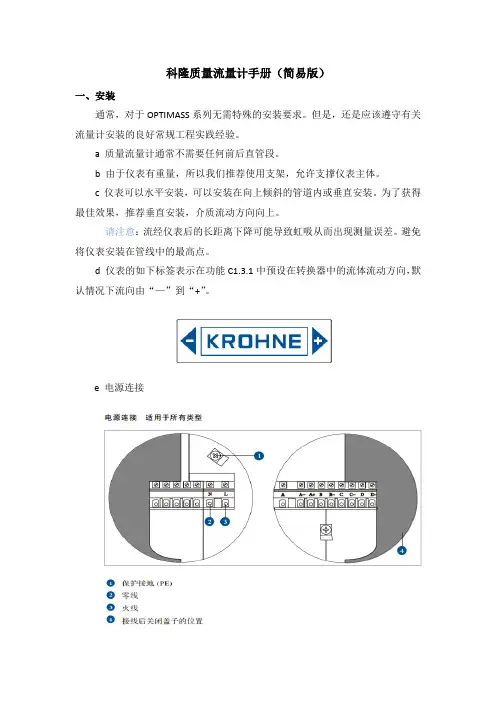
d 仪表的如下标签表示在功能C1.3.1中预设在转换器中的流体流动方向,默认情况下流向由“—”到“+”。
e 电源连接请注意:通电前,请确认仪表铭牌上的数据、电源电压和频率范围f 输出连接若仪表为电流输出时,请连接接线端子A+和A,其中端子A+为“+”端子A 为“—”,如下图:二、参数设置a 科隆质量流量计OPTIMASS1300系列流量见下表,可在菜单A4.3中设置输出范围。
为避免输出错误,量程最小值最好设置为0。
b 仪表有流量累积的功能,若第一个测量页面无累积流量显示可在菜C6.3.1选择两行显示,其单位可在C6.7.13中更改。
三、零点校准(菜单C1.1.1)装置完好性检查后,使用前必须在仪表上设置零点。
在零点设置前,必须先完成装置的所有改装/调节。
零点设置后对装置的任何改装或更改都将导致仪表性能不可靠,如发生这种情况,则需要重新设置零点。
如要完成正确无误的零点校准,必须注意以下几点:1、传感器中必须充满具有正常工作压力和工作温度的工艺流体;2、必须将流体中的空气全部除去,尤其对于水平安装。
建议在调节前先使用高流率(大于50%)的工艺流体冲洗传感器5分钟以上;3、冲洗后,必须完全关闭相应的阀门使传感器中的流量恢复为0(传感器中充满工艺流体但处于静止状态)。
阀门开关顺序:开启仪表旁路阀门→完全关闭仪表下游阀→完全关闭仪表上游阀门→菜单零点校准(见下表)→开启仪表上游阀门→开启仪表下游阀门→关闭仪表旁路阀门。

XMC1300 Boot KitPart Number: KIT_XMC13_BOOT_001Features∙XMC1300 Microcontroller with 200KB Flash∙Detachable SEGGER J-Link∙Motor control timer∙MATH co-processor∙Motor position interface∙Digital power conversionPLEASE SEE THE FOLLOWING PAGES FOR USERS MANUALXMC1300 CPU Card For XMC1000 FamilyCPU-13A-V1XMC1300 CPU CardBoard User's Manual Revision 2.0, 2013-12-18Edition 2013-12-18Published byInfineon Technologies AG81726 Munich, Germany© 2013 Infineon Technologies AGAll Rights Reserved.Legal DisclaimerThe information given in this document shall in no event be regarded as a guarantee of conditions or characteristics. With respect to any examples or hints given herein, any typical values stated herein and/or any information regarding the application of the device, Infineon Technologies hereby disclaims any and all warranties and liabilities of any kind, including without limitation, warranties of non-infringement of intellectual property rights of any third party.InformationFor further information on technology, delivery terms and conditions and prices, please contact the nearest Infineon Technologies Office ().WarningsDue to technical requirements, components may contain dangerous substances. For information on the types in question, please contact the nearest Infineon Technologies Office.Infineon Technologies components may be used in life-support devices or systems only with the express written approval of Infineon Technologies, if a failure of such components can reasonably be expected to cause the failure of that life-support device or system or to affect the safety or effectiveness of that device or system. Life support devices or systems are intended to be implanted in the human body or to support and/or maintain and sustain and/or protect human life. If they fail, it is reasonable to assume that the health of the user or otherTrademarks of Infineon Technologies AGAURIX™, C166™, CanPAK™, CIPOS™, CIPURSE™, EconoPACK™, CoolMOS™, CoolSET™, CORECONTROL™, CROSSAVE™, DAVE™, DI-POL™, EasyPIM™, EconoBRIDGE™, EconoDUAL™, EconoPIM™,EconoPACK™,EiceDRIVER™, eupec™, FCOS™, HITFET™, HybridPACK™, I²RF™, ISOFACE™, IsoPACK™, MIPAQ™, ModSTACK™,my-d™, NovalithIC™, OptiMOS™, ORIGA™, POWERCODE™, PRIMARION™, PrimePACK™, PrimeSTACK™, PRO-SIL™, PROFET™, RASIC™, ReverSave™, SatRIC™, SIEGET™, SINDRION™, SIPMOS™, SmartLEWIS™, SOLID FLASH™, TEMPFET™, thinQ!™, TRENCHSTOP™, TriCore™.Other TrademarksAdvance Design System™ (ADS) of Agilent Technologies, AMBA™, ARM™, MULTI-ICE™, KEIL™, PRIMECELL™, REALVIEW™, THUMB™, µVision™ of ARM Limited, UK. AUTOSAR™ is licensed by AUTOSAR development partnership. Bluetooth™ of Bluetooth SIG Inc. CAT-iq™ of D ECT Forum. COLOSSUS™, FirstGPS™ of Trimble Navigation Ltd. EMV™ of EMVCo, LLC (Visa Holdings Inc.). EPCOS™ of Epcos AG. FLEXGO™ of Microsoft Corporation. FlexRay™ is licensed by FlexRay Consortium. HYPERTERMINAL™ of Hilgraeve Incorporated. IEC™ of Commission Electrotechnique Internationale. IrDA™ of Infrared Data Association Corporation. ISO™ of INTERNATIONAL ORGANIZATION FOR STANDARDIZATION. MATLAB™ of MathWorks, Inc. MAXIM™ of Maxim Integrated Products, Inc. MICROTEC™, NUCLEUS™ of Mentor Graphics Corporation. MIPI™ of MIPI Alliance, Inc. MIPS™ of MIPS Technologies, Inc., USA. muRata™ of MURATA MANUFACTURING CO., MICROWAVE OFFICE™ (MWO) of Applied Wave Research Inc., OmniVision™ of OmniVision Technologies, Inc. Openwave™ Openwave Systems Inc. RED HAT™ Red Hat, Inc. RFMD™ RF Micro Devices, Inc. SIRIUS™ of Sirius Satellite Radio Inc. SOLARIS™ of Sun Microsystems, Inc. SPANSION™ of Spansion LLC Ltd. Symbian™ of Symbian Software Limited. TAIYO YUDEN™ of Taiyo Yuden Co. TEAKLITE™ of CEVA, Inc. TEKTRONIX™ of Tektr onix Inc. TOKO™ of TOKO KABUSHIKI KAISHA TA. UNIX™ of X/Open Company Limited. VERILOG™, PALLADIUM™ of Cadence Design Systems, Inc. VLYNQ™ of Texas Instruments Incorporated. VXWORKS™, WIND RIVER™ of WIND RIVER SYSTEMS, INC. ZETEX™ of Diodes Zetex Limited.Last Trademarks Update 2011-11-11Table of Contents1Overview (7)1.1Key Features (7)1.2Block Diagram (7)2Hardware Description (8)2.1Power Supply (8)2.2Reset (9)2.3Clock Generation (9)2.4Boot Option (9)2.5Debug Interface and virtual com port (9)2.6LED (9)2.7Potentiometer (10)2.8Application Card connector (10)3Production Data (12)3.1Schematics (12)3.2Layout and Geometry (15)3.3Bill of Material (15)List of FiguresFigure 1Block Diagram of XMC1300 CPU Card (7)Figure 2XMC1300 CPU Card (8)Figure 3Power Supply circuit (8)Figure 4LEDs circuit (10)Figure 5Potentiometer Circuit (10)Figure 6Pinout of the 2x30 pin edge connector (11)Figure 7Schematic 1 of 2 XMC1300 CPU Card (13)Figure 8Schematic 2 of 2 XMC1300 CPU Card (14)Figure 9XMC1300 CPU Card layout and geometry (15)List of TablesTable 1Debug connector X201 (9)Table 2LEDs Pinout (10)Table 3XMC1300 CPU Card (15)IntroductionThis document describes the features and hardware details of the XMC1300 CPU Card. This board is mounted with ARM® Cortex TM-M0 based XMC1300 Microcontroller from Infineon Technologies AG. This board is part of Infineon’s XMC1000 Application Kits1 OverviewThe XMC1300 CPU board (CPU-13A-V1) houses the XMC1300 Microcontroller and a 2x30 pin edge for application expansion. The board along with application cards (e.g. Colour LED Card, White LED Card) demonstrates the capabilities of XMC1300. The main use case for this board is to demonstrate the generic features of XMC1300 device including tool chain. The focus is safe operation under evaluation conditions. The board is neither cost nor size optimized and does not serve as a reference design.1.1 Key FeaturesThe XMC1300 CPU Card is equipped with the following features∙XMC1300 (ARM®Cortex TM-M0 based) Microcontroller, TSSOP38∙Connection to XMC1300 application cards via card edge connector∙Detachable J-Link debugger and UART virtual COM port, with micro USB connector∙Six user LEDs∙Potentiometer, connected to analog input P2.5∙Power supply via Micro-USB connector1.2 Block DiagramFigure 1 shows the functional block diagram of the XMC1300 CPU Card.Features include:−On board Debugger, for downloading and debugging of application code−Virtual com port for uart communication with terminal program e.g. Hyperterminal.−2x30 card edge connector, for extension to application card e.g. Colour LED Card and White LED Card.− 6 User LEDs connected to GPIO P0.0, P0.1, P0.6, P0.7, P0.8 and P0.9−Variable resistor R110 connected to Analog input P2.5−All the pins of XMC1300 are accessible via the connector JP101, JP102, JP103 and JP104Figure 1 Block Diagram of XMC1300 CPU Card2 Hardware DescriptionThe following sections give a detailed description of the hardware and how it can be used.Figure 2 XMC1300 CPU Card2.1 Power SupplyXMC1300 CPU Card is powered from the micro USB connector (5V); however, there is a current limit that can be drawn from the host PC through USB. If the CPU-13A-V1 board is used to drive other application board (e.g. Colour LED Card, White LED Card) and the total current required exceeds 500mA, then the board needs to be powered by external power supply connected to VDD and GND connection on board.The XMC1300 device can operate by power supply of 1.8V till 5.5Vdc. On this board, 5Vdc is used to power the XMC1300 device. However, if user wants to power the XMC1300 device with 3.3Vdc, then, set Jumper at JP201 to 3.3V side.Figure 3 Power Supply circuit2.2 ResetXMC1300 does not have a reset pin, hence, user can unplug and replug the USB cable to achieve power-on master reset.2.3 Clock GenerationNo external clock source is required. XMC1300 has two internal oscillators DCO1 and DCO2. DCO1 has a clock output of 64MHz. DCO2 is used to generate the standby clock running at 32.768KHz which used for Real Time Clock too. The main clock, MCLK and fast peripherial clock, PCLK, are generated from DCO1’s output.2.4 Boot OptionAfter power-on reset with master reset, XMC1300 device will enter different boot mode depend on the BMI (Boot Mode Index) value stored in XMC1300’s f lash configuration sector 0 (CS0). The BMI value pre-programmed on the XMC1300 device on CPU Card is User mode with debug enabled, hence, the XMC1300 device will start to run the application code in its embedded Flash after power on reset.2.5 Debug Interface and virtual com portXMC1300 CPU Card has on-board debugger which supports Serial Wire Debug (SWD) and Single Pin Debug (SPD) as debug interface. SPD is a proprietary debugging protocol from Infineon Technologies and it requires only 1 pin for debug communication. The debugger also provides a virtual COM port which support UART communication via P1.3 (rx-in) and P1.2 (tx-out) of XMC1300. There is a 2x5 pins Header Debug connector X201.Table 1 Debug connector X2012.6 LEDThe port pins P0.0, P0.1, P0.6, P0.7, P0.8 and P0.9 are connected to LED101, LED102, LED103, LED104, LED105 and LED106 respectively. The LED is turn on by output ‘L ow’ at the port pin.Figure 4 LEDs circuit2.7 PotentiometerXMC1300 CPU Card provides a potentiometer R110 for ease of use and testing of the on-chip analog to digital converter. The potentiometer is connected to the analog input P2.5. The analog output of the potentiometer is the same the VDDP voltage supplied to the XMC1300 device.Figure 5 Potentiometer Circuit2.8 Application Card connectorXMC1300 CPU Card has a 2x30 pins card edge connector. The mating connector is SAMTEC HSEC8-130-01-L-RA-XX.Figure 6 Pinout of the 2x30 pin edge connector3 Production Data3.1 SchematicsThis chapter contains the schematics for the XMC1300 CPU Card:∙Figure 7: CPU, Pin Headers, Potentiometer and LED and 60pin Edge connector ∙Figure 8: On-board Debugger, Power Supply3.2 Layout and GeometryFigure 9 XMC1300 CPU Card layout and geometry 3.3 Bill of Materialw w w.i n f i n e o n.c o m。

光端机说明书数字式视.音频及控制数据光端机目录1、概要 (2)2、一般安全要求 (2)3、应用场合 (2)4、数字光端机产品分类及产品说明 (3)5、数字光端机技术参数 (11)6、产品技术特点 (12)7、系统连接图 (13)8、安装步骤 (13)9、控制数据、音频信号端口及接口线定义 (15)10、简单故障检查分析与排除2111、 ..................................................................................................................... 附件22一、概要非常感谢您选用我公司生产的高可靠数字视音频及控制数据光传输系统!持续为用户提供优质产品和优质服务是我们的目标。
为确保您正确、安全地使用我们的产品,敬请您在使用前仔细阅读本手册,以减少或避免在安装和使用过程中可能遇到的问题。
视音频光端机因视频路数、音频路数、控制数据路数及其信号传输方向的不同,使光端机的型号繁多。
本手册中将同一基本配置衍生的系列产品归为一个产品组,同一产品组产品的使用及连接方法类同。
对每一产品组就其主要代表性型号的配置及使用连接方法都进行了详细说明。
实际购买的产品在型号、配置上不一定会与说明书列出的严格一致,但都在说明书的范围以内。
请根据产品的基本配置,查找归类的产品组,再进一步详细了解使用及连接方法。
本手册为3500、4500 两大系列产品线所有型号数字视音频及控制数据光端机的通用说明书。
请阅读下列安全注意事项,以避免人身伤害,并防止本产品或与其相连的任何其他产品受到损坏。
为了避免可能发生的危险,本产品只可在规定范围内使用。
只有我公司授权的技术人员方可执行维修。
□使用适当的电源。
仔细核对产品的电源类型以及正负极性。
□正确的连接和断开。
当设备正处于上电状态时,请勿随意连接和断开数据线。
□正确的信号线连接。

Knowledge BaseArticle Type: InstructionsInstalling Stripper andCompression beam bushings onCPM machines, models, 30, 40 50and 60 machinesWARNINGNever work on, clean or service this unit, control panel or any machine or open or remove any protective cover, guard, grate, door, or maintenance panel until the power or energy sources has been turned off, locked out / tagged out, and all moving parts have come to a complete stop and or blocked to prevent movement. Machinery is dangerous –avoid personal injury and or death by following manufacture, Local, and OHSA safety procedures. Contact Columbia Machine for safety decals, guards, horns and beacons.Description:Instructions on “How to” properly install CPM Stripper and Compression beam bushings, and product comparison on fiber, plastic and steel bushings.Installing CPM Stripper and Compression beambushings, plastic (run dry) or steel (greased)∙All CPM series machines from 30, 40, 50, 60∙See part details below for part #s and other details.When installing the new beam bushings here are some guide lines:∙Make sure columns are smooth.∙Make sure the bushings are kept as matched pairs.∙Before installing, fill a clean bucket or bowl with about 5 inches of clean hydraulic oil.∙Drop the pairs in oil, and then install.∙This oil SHOULD NOT be used continuously, or on a regular bases.∙Do not sand bushing before installing, install bushings as received. Plastic bushings:∙Regular heating of columns and the need for oiling means you have other problems going on.1. First, the oil will help when removing the old bushings andhelp on installation of the new replacements.2. The oil film on the face (against the column) will help stopheating during start up and brake in.3. If columns ever heat up, a lightweight oil like WD-40 can beapplied to columns.Steel bushings:∙The steel bushing are greased once a shift or as needed based on the grease film left on the column surface.Typical CPM Bushing LayoutWhen replacing bushings, it isadvisable the replace the sealsProduct ComparisonCPM Column Bushings for Stripper and Compression BeamsPart Number: 675.200.19.000 (used from 1994 to 2005)Simple Description: Fiber bushingMaterial Description: Fabric reinforced resin with incorporatedsolid lubricant.Expected Life:Heavy production (multiple shifts, 5+ days/week): 3 mos.Moderate production (single shift, 5 days/week): 6 mos.+Number needed for machine: 8 (4 on each beam)Advantages: no greasing, only initial oil lubrication, lower costDisadvantages: replaced more often/wear out quicker comparedto cast iron, flange occasionally breaks off requiring raising of column to remove bushingPart Number: 675.200.19V (used 2005 to present)Simple Description: Plastic bushingMaterial Description: Low friction polymer bearing material.Expected Life:Heavy production (multiple shifts, 5+ days/week): 3 mos.Moderate production (single shift, 5 days/week): 6 mos.+Number needed for machine: 8 (4 on each beam)Advantages: no greasing, only initial oil lubrication, lower cost,flange does not break off, possible longer life over fabric bushingDisadvantages: replaced more often/wear out quicker comparedto cast ironPart Number: 485.2.16S (used 1980 to present)Simple Description: Metal bushingMaterial Description: Cast iron.Expected Life:Heavy production (multiple shifts, 5+ days/week): 3 yearsModerate production (single shift, 5 days/week): 5 yearsNumber needed for machine: 8 (4 on each beam)Advantages: long lifeDisadvantages: requires periodic greasing, grease build-up onmachine, more expensive than plastic or fiber。

WINDOWS MACORScanSnap ConnectTablet/ iPad SmartPhonesOne button scanning to PDF or JPEG▪Fast double-sided scanning at 24 images▪per minuteOrganize and search documents▪and business cardsScan to email and scan to print functions▪Scan directly to Microsoft Word or Excel▪Supports Windows and Mac▪AC or USB powered for increased portability▪Organize your business Organize your life.Seamlessly Sync to iPad/ iPhone & Android devices over Wi fiDocs Dropbox EVERNOTE SharePointScan to CloudMicrosoft& many more!Specifi cations OverviewTechnical Specifi cationsScanner type:ADF (Automatic Document Feeder), Duplex scanningScanning modes Colour / Greyscale / B&W / Automatic detectionScanning speed 1Up to 12 ppm / 24 ipm (AC powered),Up to 4 ppm / 8 ipm (USB powered),fo details please visit: http://www.fujitsu.ca/products/scansnap/s1300i Paper Size Business Cards to Legal sizePaper Weight17 to 28 lbFeeder Capacity Maximum 10 sheets at Letter size, 20 lbDriver 2ScanSnap Manager / (does not support TWAIN/ISIS™)Output formats PDF, searchable PDF or JPEGDimensions (WxDxH)328.4x 9.9 x 7.7 c mWeight 3.0kgEnvironmental compliance EnergyStar® and RoHSSystem RequirmentsOperating System Windows®74(32/64 bit), Vista (32/64 bit), XP, 2000 Professional5 TechnologyMac OS X v10.7, v10.6, v10.5, v10.4Minimum System Requirements For details please visit http://www.fujitsu.ca/products/scansnap/s1300iIn The BoxHardware One USB cable and one USB power cableACadapter“Getting Started Guide”Bundled Software ScanSnap Manager (Windows® and Macintosh)ABBYY FineReader for ScanSnap (Windows®and Macintosh)ScanSnap Organizer (Windows® only)PFU CardMinder™ (Windows® only)Scan to Microsoft SharePoint (Windows® only)Cardiris (Macintosh only)Rack2–Filer v5.0 (for Windows®) only with ScanSnap Deluxe1) Scanning speeds may vary due to the system environment used2) TWAIN or ISIS™ applications cannot be used directly These applications can be launched by ScanSnap if they support PDF or JPEG fi le types3) Stacker external attachments excluded4) With Service Pack 4 or higher5) With Service Pack 2 or higherDeluxe version availableThe ScanSnap S1300i Deluxe comesbundled with Rack2-Filer softwarewhich providesthe look and feel of paperin an electronic environment.Warranty Plus1 year Advance exchange warranty anywhere in Canada.For more details visit: http://www.fujitsu.ca/warranty/scanner/Supports Windows & Mac OSI ncludes drivers and applications for both Windows and Mac OSUser Friendly & ConvenientScan to PDF or JPEG with one touchAuto detects paper size: business card to legalAuto corrects skewed imagesAuto deletes blank pagesAuto page orientationAuto detects B&W, greyscale or colour documentsEasy to use “Quick Menu”Quick Menu for Windows usersQuick Menu for MAC OS UsersOrganize Documents & Business CardsManage your scanned documents and conduct quick searching with ScanSnap Organizer(Windows® only)Automatically convert scanned images to text searchable PDF Automatically extracts contact information from business cards.Export card data to popular contact management softwareScan to email with PDF or JPEG attachmentsNew Feature:Scan to ScanSnap FolderInstantly Add or Insert scanned PDF Files/ Images to existing documents or cloud applicationsContactFujitsu Canada Inc.,155 University Avenue, Suite 1600, Toronto, Ontario M5H 3B7Website (English):1000 Sherbrooke St. West, Suite 1400, Montréal, Québec H3A 3R22Website (French):/frFujitsu and the Fujitsu logo are registered trademarks of Fujitsu Limited. Adobe, Acrobat, Adobe PDF logo are either registered trademarks or trademarks of Adobe Systems Incorporated in the United States and/or other countries. All the other trademarks mentioned herein are the property of their respectiveowners. Specifi cations are subject to change without notice.© 2012 Fujitsu Canada, Inc. All rights reserved.FCI-09.12.2012-EDocs Dropbox EVERNOTE SharePointScan to Cloud& many more!。
技术细节1.要件速览 42.尺寸图 6 2.1DFK 33GP1300 带脚架适配器的C型接口 (6)2.2DFK 33GP1300 不带脚架适配器的C型接口 (7)2.3DFK 33GP1300 带脚架适配器的CS型接口 (8)2.4DFK 33GP1300 不带脚架适配器的CS型接口 (9)3.I/O 连接器 10 3.16-pin I/O 连接器 (10)3.1.1TRIGGER_IN (10)3.1.2STROBE_OUT (11)4.光谱特征 12 4.1红外截止滤波器 (12)4.2光谱灵敏度 - P1300 (12)5.相机控制 13 5.1传感器读出控制 (13)5.1.1像素格式 (13)8-Bit Bayer Raw (13)5.1.1.15.1.1.212-Bit Packed Bayer Raw (14)16-Bit Bayer Raw (14)5.1.1.35.1.1.4YUV 4:2:2 (14)5.1.1.5YUV 4:1:1 (14)5.1.2分辨率 (14)5.1.3读出模式 (15)5.1.4帧速率 (15)5.1.5局部扫描偏移 (17)5.2图像传感器控制 (18)5.2.1曝光时间 (18)5.2.2增益 (18)5.3自动曝光及增益控制 (18)5.3.1自动曝光 (19)5.3.2自动增益 (19)自动参考值 (19)5.3.35.3.4强光缩减 (19)5.3.5自动曝光限制 (20)5.3.6自动增益限制 (20)5.4触发 (21)5.4.1触发模式 (21)5.4.2触发极性 (21)5.4.3软件触发 (22)5.4.4触发脉冲计数 (22)5.4.5触发源 (22)5.4.6触发重叠 (23)5.5触发定时参数 (23)5.5.1触发延迟 (23)5.5.2触发去抖时间 (23)5.5.3触发遮罩时间 (24)5.5.4触发噪声抑制时间 (24)5.6数字I/O (24)5.6.1通用输入 (24)5.6.2通用输出 (25)5.7频闪 (25)5.7.1频闪启用 (25)5.7.2频闪极性 (26)5.7.3频闪操作 (26)5.8白平衡 (26)5.8.1自动白平衡 (26)5.8.2白平衡模式 (27)手动白平衡 (28)5.8.35.9图像处理 (29)5.9.1伽玛 (29)5.9.2查找表 (29)5.10色彩处理 (30)5.10.1色调 (31)5.10.2饱和 (31)5.10.3色彩校正矩阵 (31)5.11自动功能感兴趣的区域 (33)5.11.1自动功能ROI启用 (33)自动功能ROI预设 (34)5.11.25.11.3自动功能ROI自定义矩形 (34)5.12用户设置 (35)5.12.1用户设置选择器 (35)5.12.2加载用户设置 (35)5.12.3保存用户设置 (36)默认用户配置 (36)5.12.46.Rev i s i o n H i story 371要件速览2尺寸图2.1DFK 33GP1300 带脚架适配器的C型接口2.4DFK 33GP1300 不带脚架适配器的CS型接口3I/O 连接器3.16-pin I/O 连接器相机后视图1开极闸M OS F E T最大限制0.2A(ID)!2启动电流最低条件3.5mA!3 G:地O:输出I:输入3.1.1TR IGG ER_I NTRIGGER_IN线可用于将曝光时间的开始与外部事件同步。
OAP1300Powerful Outdoor Solution with High Speed AC1300 for Modern BusinessKEY FEATURES•802.11ac High Speed Dual-Band: IEEE 802.11ac concurrent dual-band with 1300Mbps wireless speed.•Multi-Device (MU-MIMO): Efficient MU-MIMO (Multiple User - Multiple Input Multiple Output) technology serves multiple devices simultaneously.•Easy Installation: Wall-mount or pole-mounted design with easy installation kit.•Rugged Construction: IP56 weatherproof housing can perform normally under rigorous weather.•Designed for High Density Usage: Supports up to twohundred users simultaneously (one hundred users per band), ideal for crowded environments and BYOE (Bring Your Own Everything) workplace Wi-Fi connection.•Multiple SSIDs for Security Management: Supports up to 32 SSIDs (16 x 2.4GHz & 16 x 5GHz) ideal for multiple departments, user groups, customers or guests.•Fast Roaming: Roams smoothly between APs without lag or interruption, ensuring top performance for video and voice streaming applications.•Wide Coverage & High Sensitivity: Adjustable RF output power and high receiver sensitivity for wide coverage across large spaces.•Seamless Mobility: 1.5x greater coverage than typical APs for blanket coverage to ensure seamless connectivity for Wi-Fi devices across enterprise environments.•Power over Ethernet In/Out: Supports IEEE 802.3at PoE and IEEE 802.3af PSE, PoE out (802.3af) to power another PoE device such as IP camera or outdoor AP.•Built -in Lighting Arrester: Built-in withstands up to 10 kAcurrent provides lightning protection for your wireless equipment. •Built -In RADIUS Server: With management for up to 256 user accounts.•Central Management: Edimax Pro Network Management Suite (NMS) for easy and intuitive web-based central management. AP built –in with NMS supports AP array architecture.•Works with Office 1-2-3 Wi-Fi System/Master AP : The Office 1-2-3 system is a simple, secure, complete and expandable office Wi-Fi solution. OAP1300 with upgradeable firmware (OAP1300 Office +1) for full Office 1-2-3 system compatibility, the integration supports guest, employee and device networks to offer a perfect solution for office with outdoor area or warehouse.The OAP1300 features an IP56 rated weatherproof housing and provides a premium wireless solution designed for SMBs which demand elite network performance. Theproduct features the latest 2 x 2 IEEE 802.11ac technology for wireless speeds up to 1300Mbps. A wall or pole-mounted design and industrial-grade build quality combined with user-friendly operation and extensive feature set, make an ideal high-performance solution for demanding day-to-day enterprise outdoor long range Wi-Fi and Point-to-Point applications such as WISP clients, Internet sharing, wireless surveillance in multi-tenant units (MTUs) and multi-dwelling units (MDUs) with PoE and easy installation mounting kits.For businesses that demand security, flexibility and speed – the Edimax Pro series has a wide range of potentialapplications from office environments to schools, campuses, hotels and hospitals. Multiple SSIDs can be configured for different departments or user groups and a built-in RADIUS server provides additional verification with a scalable AP array architecture for central management of multiple access points. High-density capacity for up to 200simultaneous clients (100 clients per band), ideal for BYOE workplaces or other environments with a high volume of clients and wireless devices, and fast roaming allows for seamless transitions between multiple access points. Power over Ethernet (PoE) support and an intuitive web-based management interface provide deployment flexibility and extensive management options for company MIS departments and network administrators.When performance and security are critical for yourbusiness, you need products that are engineered for your industry. The Edimax Pro series is designed to help your business and provide the connectivity that you rely on every day, with safety and effectiveness guaranteed, and the OAP1300 offers the highest level of wireless performance on the market today.2 x 2 AC Dual-Band Outdoor PoE Access PointOAP1750 Outdoor Dual-Band PoE Access PointOAP1300Outdoor Dual-BandPoE Access PointOAP1300Outdoor Dual-BandPoE Access PointANT-2412D1 / ANT-2412D2ANT-5815D1 / ANT-5815D2Outdoor Antenna2.4GHz 5GHzLong-rangeRF Communication Less than 3KMOUTDOOR APPLICATION2.4GHz2D Radiation Pattern@ Vertical5GHz2D Radiation Pattern@ Vertical2.4GHz2D Radiation Pattern@ Horizontal5GHz2D Radiation Pattern@ HorizontalIP56 RatedWeatherproof& DustproofAC1300 Dual-BandPoE IP Camera802.3afPoE SwitchPoE OUT PoE IN802.3afCentral Network Management: NMSWork with Edimax Pro NMS (Network Management Suite)* web-based wireless network management software. Company MIS administrators can plan and manage Edimax Pro access points’ powerful functionality according to their office space using an easy, remote web-based interface which includes a dashboard, map view, traffic statistics and wireless client list for network-wide remote administration. RADIUS settings, WLAN group settings, access control, guest network settings and firmware upgrades can all be managed centrally from a single location to reduce network downtime, aid troubleshooting and optimize network performance. Graphical zone plans with Google Maps integration and setup wizards are also available for expanding and managing large networks with multiple access points, with custom floor plans, visual overviews and easy drag-and-drop icons for quick access to key performance and monitoring information.*NMS is built-in with Edimax Pro CAP, WAP series & OAP1750 access point.RF SpecificationsFrequency Band •Radio Ⅰ: 802.11b/g/n 2.412~2.484(GHz) •Radio Ⅱ: 802.11a/n/ac 5.18~5.24(GHz),5.26~5.32(GHz), 5.5~5.7(GHz), 5.745~5.825(GHz) (The supported frequency band is restricted by local regulations.)Operation Channels •2.4GHz : US/Canada 1-11; 2.412~2.462GHz Europe 1-13; 2.412~2.472GHz Japan 1-14; 2.412~2.484GHz•5GHz : Country dependent for the following ranges: US/Canada:Band 1:36, 40, 44, 48; 5.180~5.240(GHz) Band 2: 52、56、60、64;5.260~5.320(GHz)Band 3: 100、104、108、112、116、120、124、128、132、136、140;5.500~5700(GHz)Band 4:149, 153, 157, 161, 165; 5.745~5.825(GHz) Europe:Band 3: 100、104、108、112、116、120、124、128、132、136、140; 5.500~5700(GHz) Transmit Power (CE: 20dBm or lower, FCC:23dBm or lower)802.11b 20dBm@1Mbps 20dBm@2Mbps ************* 20dBm@11Mbps 802.11g 20dBm@6Mbps 20dBm@9Mbps 20dBm@12Mbps 19dBm@18Mbps 19dBm@24Mbps 18dBm@36Mbps 17dBm@48Mbps 17dBm@54Mbps 802.11gn (2.4G) 20dBm@MCS0/8 20dBm@MCS1/9 20dBm@MCS2/10 19dBm@MCS3/11 19dBm@MCS4/12 18dBm@MCS5/13 17dBm@MCS6/14 17dBm@MCS7/15 802.11a 20dBm@6Mbps 20dBm@9Mbps 20dBm@12Mbps 19dBm@18Mbps 19dBm@24Mbps 18dBm@36Mbps 17dBm@48Mbps 16dBm@54Mbps 802.11an(5G) 20dBm@MCS0/8 20dBm@MCS1/9 19dBm@MCS2/10 19dBm@MCS3/11 18dBm@MCS4/12 17dBm@MCS5/13 16dBm@MCS6/14 15dBm@MCS7/15 802.11ac 20dBm@MCS0 20dBm@MCS1 20dBm@MCS2 19dBm@MCS319dBm@MCS4 18dBm@MCS5 17dBm@MCS6 17dBm@MCS7 17dBm@MCS8 15dBm@MCS9Receiver Sensitivity802.11b ≤-93dBm@1Mbps ≤-85dBm@11Mbps 802.11g ≤-86dBm@6Mbps ≤-70dBm@54Mbps 802.11gn (2.4G) ≤-86dBm@MCS0 ≤-62dBm@MCS8 ≤-57dBm@MCS9 802.11a ≤-85dBm@6Mbp ≤-68dBm@54Mbps 802.11an(5G) ≤-85dBm@MCS0 ≤-64dBm@MCS7 802.11ac ≤ -85dBm@MCS0 ≤ -61dBm@MCS8 ≤ -54dBm@MCS9ManagementDeployment Standalone (AP mode)Managed AP mode :1) Managed by AP Controller (APC500), Edimax Pro Master AP with NMS software2) Managed by Office 1-2-3 Master AP (with dedicated firmware of OAP1300 Office +1)Configuration HTTP/HTTPS SNMP v1, v2c, v3 CLI (Telnet, SSH)RADIUS Server Built-In Auto-Channel Y Private MIB YPackage Contents Access Point AC1300 Outdoor PoE Access PointAntenna2.4GHz /5GHz Omni x 2 Mounting Bracket Wall-Mount & Pole-Mount Bracket KitCableEthernet CableCD / QuickInstallation Guide CD (User Manual & Multi-Language Quick Installation Guide) / Printed English Quick Installation GuideAccessories OptionalGP-101IT IEEE802.3at PoE InjectorSPECIFICATIONS2 x 2 AC Dual-Band Outdoor PoE Access PointHardware LAN Interface Giga x 2PoE LAN1: PoE IN (802.3af/at) LAN2: PoE OUT (802.3af) Antenna Type: 2 x ExternalGain: 3.9dBi (2.4GHz), 4.4dBi (5GHz)Power 802.3at (PoE Injector Optional)Dimensions (L x W x H) 27.18 x 12.09 x 3.5 cmWeight592g PowerConsumption (Full Loading) 15W Mounting Pole/Wall Reset ResetLED Indicator Power, Status, LAN(PD) , LAN(PSE), 2.4G, 5G Environmental Conditions Operating Temperature: -40°C (-40°F) to 60°C (140°F)Operating Humidity: 90% or LessPower Saving 802.3az Internal Buzzer YHousing Outdoor IP56 Weatherproof RatedWireless Standard 802.11 a/b/g/n/ac Concurrent Dual-BandNo. of Radios 2 Receiver Sensitivity ≤ -93Bm Certification CE/FCCFast Roaming YNumber of SSIDs 16 (2.4GHz) + 16 (5GHz)Performance Maximum Data Speed400 + 866Mbps Concurrent Clients Up to 100 Per RadioSecurity Encryption WEP / WPA / WPA2Wireless L2 Isolation Y Station Isolation Y IEEE 802.1x Authenticator Y EAP Authentication PEAP Hidden SSID Y MAC Address Filter Y Wireless STA Y Rogue APDetection (w/ NMS) YSoftware Wireless Mode AP / WDS AP / WDS Bridge / Client802.1q VLAN Y (VID = 1-4095)Spanning Tree RSTP QoSWMM (802.11e) Max Associated Station No. Pass-Through IPv6 and VPN (PPTP, L2TP/IPsec)DSCP (802.1p) Y Multicast Rate up to 54MbpsYCopyright © 2018 Edimax Technology Co. Ltd. All rights reserved.Maximum performance, actual data rates, and coverage will vary depending on network conditions and environmental factors. Product specifications and design are subject to change without notice.。
P/N: 1802000060014 *1802000060014*VPort P06-1MP-M12 Series Quick Installation GuideMoxa IP CameraVersion 5.1, January 2021Technical Support Contact Information/support2021 Moxa Inc. All rights reserved.OverviewThe compact VPort P06-1MP-M12 cameras provide an HD (720P, 1280 x 720) video image, and feature an H.264/MJPEG IP dome, giving them the versatility and ruggedness to excel in many different installations and environments for mobile IP video surveillance applications. In addition, the cameras are compliant with mandatory sections of EN 50155, covering operating temperature, power input voltage, surge, ESD, and vibration, as well as conformal coating and power insulation, making them suitable for a variety of industrial applications. The cameras feature vandal-proofing (EN 62262 IK10), a -25 to 55°C or -40 to 70°C (T models) operating temperature range, a rugged M12 Ethernet port, 1 audio input, PoE power inputs, IP66 rain and dust protection, a dehumidifying membrane, and a selectable lens.Ordering InformationMoxa’s VPort P06-1MP-M12 is shipped with the following item:•VPort P06-1MP-M12 (lens included)If this item is missing or damaged, please contact your customer service representative for assistance.The following models are available:EN 50155, T1 EN 50155, TX LensFocal-length Line-in/ Microphone-25 to 55°C -40 to 70°CVPort P06-1MP -M12-CAM25 VPort P06-1MP-M12-CAM25-T2.5 mm Line-inVPort P06-1MP -M12-MIC-CAM25 VPort P06-1MP-M12-MIC-CAM25-T2.5 mm Microphone-inVPort P06-1MP -M12-CAM36 VPort P06-1MP-M12-CAM36-T3.6 mm Line-inVPort P06-1MP-M12-MIC-CAM36 VPort P06-1MP-M12-MIC-CAM36-T3.6 mm Microphone-inVPort P06-1MP -M12-CAM42 VPort P06-1MP-M12-CAM42-T4.2 mm Line-inVPort P06-1MP-M12-MIC-CAM42 VPort P06-1MP-M12-MIC-CAM42-T4.2 mm Microphone-inVPort P06-1MP -M12-CAM60 VPort P06-1MP-M12-CAM60-T6.0 mm Line-inVPort P06-1MP-M12-MIC-CAM60 VPort P06-1MP-M12-MIC-CAM60-T6.0 mm Microphone-inVPort P06-1MP -M12-CAM80 VPort P06-1MP-M12-CAM80-T 8.0mm Line-inVPort P06-1MP -M12-MIC-CAM80 VPort P06-1MP-M12-MIC-CAM80-T8.0mm Microphone-inVPort P06-1MP -M12-CAM25-CT VPort P06-1MP-M12-CAM25-CT-T 2.5mm Line-inVPort P06-1MP-M12-MIC-CAM25-CT VPort P06-1MP-M12-MIC-CAM25-CT-T 2.5mm Microphone-inVPort P06-1MP -M12-CAM36-CT VPort P06-1MP-M12-CAM36-CT-T3.6 mm Line-inVPort P06-1MP-M12-MIC-CAM36-CT VPort P06-1MP-M12-MIC-CAM36-CT-T3.6 mm Microphone-inVPort P06-1MP -M12-CAM42-CT VPort P06-1MP-M12-CAM42-CT-T4.2 mm Line-inVPort P06-1MP-M12-MIC-CAM42-CT VPort P06-1MP-M12-MIC-CAM42-CT-T4.2 mm Microphone-inVPort P06-1MP -M12-CAM60-CT VPort P06-1MP-M12-CAM60-CT-T6.0 mm Line-inVPort P06-1MP-M12-MIC-CAM60-CT VPort P06-1MP-M12-MIC-CAM60-CT-T6.0 mm Microphone-inVPort P06-1MP- M12-CAM80-CT VPort P06-1MP-M12-CAM80-CT-T8.0mm Line-inVPort P06-1MP-M12-MIC-CAM80-CT VPort P06-1MP-M12-MIC-CAM80-CT-T8.0mm Microphone-inScrew handle accessory packageTorx screw driver for attaching/detaching the upper case. 4 sets of nut, gasket,and spring washer formounting the camera.4 indented hexagonalhead tapping screws formounting the cameraon the ceiling.Sticker for camera mounting positions•Quick installation guide•Documentation andSoftware CD (includesUser’s Manual, QuickInstallation Guide, andVPort Utility)•Warranty cardNOTE Check the model name on the VPort’s side label to determine if the model name is correct for your order.NOTE This product must be installed in compliance with your local laws and regulations.Features•1/2.7” HD progressive CMOS image sensor•High image quality with WDR (wide dynamic range) and DNR (Digital Noise Reduction) supported•Minimum illumination up to 0.2 lux (color)•Supports MJPEG and H.264 Dual Codecs•Provides 3 video streams for H.264 and MJPEG simultaneously •Video stream up to 30 frames/sec at WXGA (1280 x 800) resolution •Supports video quality configuration with fixed bit rate (CBR) and fixed quality (VBR)•Video latency under 200 ms•DynaStream™ for network efficiency with dynamic frame rate change •CBR Pro™ supported for high image quality with limited bandwidth transmissions•WXGA, 720P, SVGA, Full D1, 4CIF, VGA, CIF, QCIF resolution •TCP, UDP, and HTTP network transmission modes•Supports DHCP OPT66/67 for automatic configuration from TFTP server, making it easy to batch configure several units •Supports RTSP streaming•Supports multicast (IGMP) video streaming•Supports SNMP (V1/V2C/V3) for network system integration and management•Supports QoS (ToS) for transmission priority•Built-in web server for easy configuration•Accessible IP filtering•UPnP supported•Complies with all EN 50155 mandatory test items**This product is suitable for rolling stock railway applications, as defined by the EN 50155 standard. For a more detailed statement, click here: /doc/specs/EN_50155_Compliance.pdf• 1 10/100BaseT(X) port with M12 D-code connector• 1 audio input with water-proof RCA-type connector•IP66 rain and dust protection, with dehumidifying membrane •PoE (Power-over-Ethernet, IEEE 802.3af) supported•EN 62262 IK9 level vandal resistance•-25 to 55°C (EN 50155, Class T1), or -40 to 70°C (EN 50155. Class TX) operating temperature for rolling stock environments•CE, FCC, UL 60950-1•Built-in tamper alarm and Video Motion Detection (VMD)•Pre, Trigger, and post snapshot images supported•Sequential snapshot images supported•Supports SMTP and FTP for alarm message transmission •Supports HTTP event server•5-year warrantyProduct DescriptionAppearance•4-pin D-code M12 Ethernet connector: Can be used for both the PoE power supply (Mode A) and Auto MDI/MDI-X Ethernet connectionNOTETo connect the VPort P06-1MP-M12 to a network, use anEthernet cable with D-code M12 connector and an M12 PoE switch or RJ45 PoE switchM12 D-code to M12 D-code cableM12 PoE switch (e.g., TN-5508-4PoE)M12 D-code and RJ45 cableRJ45 PoE switch (e.g., EDS-P510)Transparent Dome cover 4-pin D-code M12 Ethernet connectorRCA female Connector(only available in models with line-in audio)Solid plastic top coverAluminum bottom plateTorx screw for top coverBuilt-in Microphone (-MIC model)NOTE The power input rating of the VPort P06-1MP-M12 is 48 VDC,0.12 A, with maximum power consumption approximately 6 W. NOTE The equipment is designed for in building installation only and is not intended to be connected to exposed (outside the plant)networks•RCA female connector: The VPort P06-1MP-M12 supports one audio input with RCA female connector. The audio will be digitized and compressed as an audio stream for network transmission with the video stream.NOTE RCA audio connectors are popular and easily found in the market.If you require any other kind of audio connector, please contactyour Moxa sales representative for customization service. •Solid plastic top cover: This top cover can be removed for tuning the camera lens position.•Transparent dome cover: The VPort P06-1MP-M12 is designed witha transparent PC dome cover, which is vandal-proof and satisfies EN62262 (IEC 62262) Class IK9 requirements.• 2 Torx screws for top cover: These 2 torx screws are designed with anti-shedding to make installation more convenient. Use the L-type torx screwdriver to remove or attach the top cover.•Built-in microphone: VPort P06-1MP-M12-MIC series products have a built-in microphone, and can simultaneously display or record live video and audio.NOTE The color of the form factor can be customized based on your installation environment. Please contact your Moxa salesrepresentative for customization service.Inside the Camera• Mounting screw holes: There are 4 mounting screw holes for mounting the VPort P06-1MP-M12 on the ceiling or the accessory. •Thumb screw for fixing the lens’s position: To tune the lens’s position, loosen the thumb screw, and then retighten it after the position tuning is done.•Lens with fixed focal length: The VPort P06-1MP-M12 seriesincludes models with 3 different focal lengths. Choose the appropriate focal-length lens based on the viewing angle and object distance. •Hardware reset button: Use a pointed object to depress the reset button to reboot or restore factory defaults. Reboot: press the button one time.Factory default: press the button and hold in for at least 90 sec. •Calibration for rotating lens (0 to 360°): Rotate the lens to get the optimal image. When done, mark the position of this calibration for future placement or mass installation.•Calibration for tuning lens’s vertical position (0 to 90°): After tuning the lens’s vertical position, mark the position of this calibration for future placement or mass installation.•Calibration for tuning lens’s horizontal position (±30°): After tuning the lens’s horizontal position, mark the position of this calibration for future placement or mass installation.Hardware InstallationStep 1: Open and remove the top cover. Use the torx screwdriver to loosen the top cover screws.Step 2: Use the installation sticker for drilling the holes. There are 3 types of installation.Microphone line (-MIC model)a. Mounting with 4 mounting screws To mount the camera on the ceiling, drill a hole through the grayportion of the sticker and then mount the camera with the 4 nut/gasket/spring-washer sets and 4 indented hexagonal head tapping screws.b. Mounting with the side-cable-out adapter Use the side-cable-out adapter (VP-SCO1) if your installation requires the cable–out on the side. Drill a hole through the blue portion of the sticker for mounting the adaptor on the surface with 3 nut/gasket/ spring-washer sets and indented hexagonal head tapping screws. Then, mount the VPort P06-1MP-M12 on the adapter with 4 M4 screws, which are provided in the VP-SCO1’s package. VP-SCO1c. Mounting with the fixed plate If you cannot use the nut/gasket/spring-washer set to mount the camera on yourVP-FP1ceiling, use the VP-FP1 fixed plate. Drill holes through the green dotted-line holes and 4 camera mounting screw holes on the sticker, and then put the VP-FP1 inside the hole. Use the 2 countersink screws to mount the VP-SP1. Finally, mount the VPort P06-1MP-M12 on the fixed plate with the 4 indented hexagonal head tapping screws.NOTE The screw hole for mounting the VP-FP1 fixed plate is a countersunk hole with 5 mm diameter, and 90° 2 x 2 mmchamfer. Take this into consideration when drilling these 2 screw holes.Step 3: Connect the camera with the 4-pin M12 D-code Ethernet connector and RCA male connector.Step 4: Loosen the thumb screw for tuning the horizontal, vertical, and rotating lens position. Once the lens position is correct, fix the thumb screw.Step 5: Fix the top cover. The installation is now complete. Software InstallationStep 1: Configure the VPort P06-1MP-M12’s IP addressWhen the VPort P06-1MP-M12 is first powered on, the POST (Power On Self Test) will run for a few moments (about 30 seconds). The network environment determines how the IP address is assigned.Network Environment with DHCP ServerFor this network environment, the unit’s IP address will be assigned by the network’s DHCP server. Refer to the DHCP server’s IP address table to determine the unit’s assigned IP address. You may also use the Moxa VPort and EtherDevice Configurator Utility (edscfgui.exe), as described below:Using the Moxa VPort and EtherDevice Configurator Utility (edscfgui.exe)1.Run the edscfgui.exe program to search for the VPort. After theutility’s window opens, you may also click on the Search buttonto initiate a search.2.When the search has concluded, the Model Name, MAC address, IPaddress, serial port, and HTTP port of the VPort will be listed in the utility’s window.You can double click the selected VPort, or use the IE web browser to access the VPort’s web-based manager (web server).Non DHCP Server Network EnvironmentIf your VPort 16-M12 is connected to a network that does not have a DHCP server, then you will need to configure the IP address manually. The default IP address of the VPort 16-M12 is 192.168.127.100 and the default subnet mask is 255.255.255.0. Note that you may need to change your computer’s IP address and subnet mask so that the computer is on the same subnet as the VPort.To change the IP address of the VPort manually, access the VPort’s web server, and then navigate to the System Configuration →Network →General page to configure the IP address and other network settings. Check Use fixed IP address to ensure that the IP address you assign is not deleted each time the VPort is restarted.Step 2: Access the VPort P06-1MP-M12’s web-based manager.Type the IP address in the web browser’s address input box and then press enter.Step 3: Install the ActiveX Control Plug-in.A security warning message will appear the first time you access the VPort’s web-based manager. The message is related to installing the VPort AcitveX Control component on your PC or notebook. Click Yes to install this plug-in to enable the IE web browser for viewing video images.NOTE For Windows XP SP2 or above operating systems, the ActiveX Control component will be blocked for system security reasons. In this case, the VPort’s security warning message window may not appear. You should unlock the ActiveX control blockedfunction or disable the security configuration to enable theinstallation of the VPort’s ActiveX Control component.Step 4: Access the homepage of VPort P06-1MP-M12's web-based manager.After installing the ActiveX Control component, the homepage of the VPort P06-1MP-M12’s web-based manager will appear. Check the following items to make sure the system was installed properly:1.Video Images2. Video InformationStep 5: Access the VPort’s system configuration.Click on System Configuration to access the overview of the system configuration to change the configuration. Model Name , Server Name , IP Address , MAC Address , and Firmware Version appear on the green bar near the top of the page. Use this information to check the system information and installation.For details of each configuration, check the user’s manual on the software CD.Wiring RequirementsYou should also pay attention to the following:•Use separate paths to route wiring for power and devices. If power wiring and device wiring paths must cross, make sure the wires are perpendicular at the intersection point.•You can use the type of signal transmitted through a wire to determine which wires should be kept separate. The rule of thumb is that wiring that shares similar electrical characteristics can bebundled together.•Keep input wiring and output wiring separate.•We strongly advise labeling wiring to all devices in the system.Dimensions (mm)Front View Bottom ViewTop View Camera with SCO1 adaptor SpecificationsInput Current 0.12 A @ 48 VDCOperating Temperature Standard Models: -25 to 55°C (-13 to 131°F)Wide Temp. Models: -40 to 70°C (-40 to158°F)Storage Temperature -40 to 85°C (-40 to 185°F)。
家庭ごみと区別して処分してくとができます。
とができます。
当社は、電子機器法に従って環境にやさ将使用过的电气和电子设备,包括电缆、配件和电池,与家庭垃圾分开处理。
2006 年 3 月 23 日后从我公司购买的电子设备可以退还给我们。
我们将根据相应的欧盟指令 WEEE(报废电子电气设备指令)和德国国家 - 电子电气设备法案 ElektroG 以环境友好的方式处
関連製品のページの/products からダウンロードできます。
に指定されている標準規格と技術デー当製品の確認に使用した測定機器が、国の基準に基づ我们声明该产品是符合标准和我们的销售文件(操作说明书,传单,目录等)上提供的技术数据。
我们保证对该产品用测量设备进行了检验,并得到我们品质部门的保证,此件产品是符合国际标准
特に技術的改善その他の開発を予告なしに実施する権利を保有しています。
(cN) 700 600。
Godex EZPi1200/EZPi1300操作手册1、Godex EZPi1200/EZPi1300条码打印机各部位介绍1.1 上盖开启钮/上盖/纸卷轴心/碳带回收轮/LCD模组/打印机心/底座遮盖1.2 碳带回收轴/按键卡楯/CF卡槽遮盖/印表头压力调整旋钮1.3 碳带供应轴/标签调整杆/橡胶滚轮/打印线调整钮/纸张侦测器1.4 LCD控制面板/折叠纸进纸口/PS2连接口或者WirelessLan天线孔/电源开关/网络连接口/USB接头/并口/串口/电源插座2、Godex EZPi1200/EZPi1300条码打印机标配安装说明2.1 碳带安装①面对机器正面,按住上盖开启钮掀起上盖;②将碳带回收轴装上机心上方(包含纸管),按住按键卡勾机心向上掀开,使打印头向上抬起;③将新的碳带装入碳带供应轴,并将碳带拉开;④将碳带由下往上拉至碳带供应轴心固定;⑤将碳带固定好后,往机体方向卷入碳带;⑥将机心压下固定后即完成碳带安装。
2.2 标签纸安装①面对机器正面,按住按键掀起上盖;②将标签放入纸卷轴心,并在两端装上纸卷挡板;③将标签纸卷置入机器里;④按住卡勾按键使机心向上掀起,使打印头向上抬起;⑤将标签由标签调整杆下方穿过,用标签调整杆依标签宽度大小固定标签两侧;⑥将机心压下固定后即完成标签安装。
2.3 吊牌安装安装吊牌卡纸时,卡纸上之孔位须对齐SENSOR箭头指示位置,并用标签调整杆将吊牌卡纸固定。
2.4 电脑连接①确认条码机电源开关是位于关闭位置;②将随机所附之电源线一端接于一般家用电源,另一端接于条码机之电源插座;③传输线一端接于条码机之接口上,另一端接于电脑,传输线的类型视所购买的设备而有所不同,请依实际的配件安装;④在纸张(碳带)装妥的情形下打开条码机电源开关,等待条码机之电源指示灯亮即可。
2.5 驱动程序安装方式①将产品光碟置入光碟机,开启“Windows Driver”文件夹;②点击条码机驱动程式安装;③依照安装视窗的指示进行安装;④选取“安装打印机驱动方式”;⑤选取安装的条码机型号;⑥指定打印机连接接口;⑦指定打印机名称并完成;⑧在打印机设定页确认所有安装设定皆正确后按下“完成”键盘,即可开始复制驱动程序文件;⑨当驱动程序文件复制结束之后即可完成驱动程序安装,在windows的控制面板的“打印机和传真”选项里即会新增刚完成安装的条码机图示3、Godex EZPi1200/EZPi1300条码打印机面板操作3.1 控制面板介绍3.2 面板操作● FEED键按下FEED键时,条码机会依所使用纸张的类型将纸送出到指定的吐纸位置。