高压直流电机7712说明书
- 格式:rtf
- 大小:2.09 MB
- 文档页数:1

Eaton 199122Eaton Moeller® series Rapid Link - Reversing starter, 6.6 A,Sensor input 4, Actuator output 2, 180/207 V DC, Ethernet IP, HANQ4/2, with manual override switchGeneral specificationsEaton Moeller® series Rapid LinkReversing starter199122120 mm270 mm220 mm1.83 kg UL approvalUL 60947-4-2RoHSIEC/EN 60947-4-2CECCCAssigned motor rating: for normal internally and externally ventilated 4 pole, three-phase asynchronous motors with 1500 rpm at 50 Hz or 1800 min at 60 Hz RAMO5-W421EIP-412RS1Product Name Catalog NumberProduct Length/Depth Product Height Product Width Product Weight CertificationsCatalog Notes Model CodeIs the panel builder's responsibility. The specifications for the switchgear must be observed.3 kW6.6 A (at 150 % Overload)480 V AC, 3-phase400 V AC, 3-phase10000 A0 VMeets the product standard's requirements.Is the panel builder's responsibility. The specifications for the switchgear must be observed.Does not apply, since the entire switchgear needs to be evaluated.0 kW2.238 kWMeets the product standard's requirements.0 V-40 °CTwo sensor inputs through M12 sockets (max. 150 mA) for quick stop and interlocked manual operation2 Actuator outputsKey switch position OFF/RESET Generation Change RASP4 to RASP5Generation change from RA-SP to RASP 4.0Generation Change RA-SP to RASP5Generation change from RA-MO to RAMO 4.0Configuration to Rockwell PLC for Rapid LinkGeneration change RAMO4 to RAMO5Rapid Link 5 - brochureDA-SW-drivesConnect - installation helpDA-SW-Driver DX-CBL-PC-3M0DA-SW-drivesConnectDA-SW-USB Driver DX-COM-STICK3-KITDA-SW-USB Driver PC Cable DX-CBL-PC-1M5DA-SW-drivesConnect - InstallationshilfeMaterial handling applications - airports, warehouses and intra-logistics ETN.RAMO5-W421EIP-412RS1.edzIL034092ZUramo5_v14.dwgramo5_v14.stpDA-DC-00004525.pdfDA-DC-00003964.pdfDA-DC-00004184.pdfDA-DC-00004523.pdfeaton-bus-adapter-rapidlink-speed-controller-dimensions-002.eps eaton-bus-adapter-rapidlink-speed-controller-dimensions-003.eps eaton-bus-adapter-rapidlink-reversing-starter-dimensions-003.eps eaton-bus-adapter-rapidlink-reversing-starter-dimensions-002.eps10.11 Short-circuit ratingRated operational power at AC-3, 380/400 V, 50 HzInput currentRated operational voltageRated conditional short-circuit current, type 1, 480 Y/277 V Rated control supply voltage (Us) at AC, 50 Hz - min10.4 Clearances and creepage distances10.12 Electromagnetic compatibility10.2.5 LiftingRated power at 575 V, 60 Hz, 3-phaseRated power at 460 V, 60 Hz, 3-phase10.2.3.1 Verification of thermal stability of enclosures Rated control supply voltage (Us) at DC - minAmbient storage temperature - minFitted with:Applikasjonsmerknader BrosjyrereCAD model Installeringsinstruksjoner mCAD model SertifiseringsrapporterTegningerManual override switchKey switch position AUTOThermistor monitoring PTCKey switch position HANDThermo-clickElectronic motor protectionShort-circuit releaseOverload cycleAC-53aNumber of pilot lightsRated control supply voltage (Us) at AC, 50 Hz - max0 VSystem configuration typePhase-earthed AC supply systems are not permitted.AC voltageCenter-point earthed star network (TN-S network)10.8 Connections for external conductorsIs the panel builder's responsibility.Coordination class (IEC 60947-4-3)Class 1Rated conditional short-circuit current, type 1, 600 Y/347 V0 ARated conditional short-circuit current (Iq)10 kABraking voltage180/215 V DC -15 % / +10 %, Actuator for external motor brakeAmbient operating temperature - max55 °CRated operational power at AC-3, 220/230 V, 50 Hz0 kWClimatic proofing< 95 %, no condensationIn accordance with IEC/EN 50178FeaturesParameterization: drivesConnectParameterization: drivesConnect mobile (App) Parameterization: KeypadParameterization: FieldbusLifespan, electrical10,000,000 Operations (at AC-3)Number of command positions2Electrical connection type of main circuitPlug-in connectionElectrical connection type for auxiliary- and control-current circuit Plug-in connectionRated control supply voltage (Us) at DC - max0 V10.9.3 Impulse withstand voltageIs the panel builder's responsibility.Braking current≤ 0.6 A (max. 6 A for 120 ms), Actuator for external motor brakeAmbient operating temperature - min-10 °C10.6 Incorporation of switching devices and componentsDoes not apply, since the entire switchgear needs to be evaluated.Current limitation0.3 - 6.6 A, motor, main circuitAdjustable, motor, main circuitCable length10 m, Radio interference level, maximum motor cable length10.5 Protection against electric shockDoes not apply, since the entire switchgear needs to be evaluated.Mounting positionVerticalMains switch-on frequencyMaximum of one time every 60 secondsClassCLASS 10 A10.13 Mechanical functionThe device meets the requirements, provided the information in the instruction leaflet (IL) is observed.10.2.6 Mechanical impactDoes not apply, since the entire switchgear needs to beevaluated.10.9.4 Testing of enclosures made of insulating materialIs the panel builder's responsibility.10.3 Degree of protection of assembliesDoes not apply, since the entire switchgear needs to be evaluated.Electromagnetic compatibilityClass AVoltage typeDCProduct categoryMotor starterOverload release current setting - min0.3 ARated control voltage (Uc)24 V DC (-15 %/+20 %, external via AS-Interface® plug)180/207 V DC (external brake 50/60 Hz)Rated operational current (Ie)6.6 AAssigned motor power at 460/480 V, 60 Hz, 3-phase3 HPRated frequency - min47 HzNumber of auxiliary contacts (normally closed contacts)Rated conditional short-circuit current (Iq), type 2, 380 V, 400 V, 415 V0 APower consumption8 W10.2.3.2 Verification of resistance of insulating materials to normal heatMeets the product standard's requirements.10.2.3.3 Resist. of insul. mat. to abnormal heat/fire by internal elect. effectsMeets the product standard's requirements.On-delay20 - 35 msLifespan, mechanical10,000,000 Operations (at AC-3)Rated operational current (Ie) at 150% overload6.6 AProtocolEtherNet/IPOverload release current setting - max6.6 A10.9.2 Power-frequency electric strengthIs the panel builder's responsibility.Overvoltage categoryIIIDegree of protectionNEMA 12IP65Rated frequency - max63 HzVibrationResistance: 10 - 150 Hz, Oscillation frequency Resistance: 57 Hz, Amplitude transition frequency on accelerationResistance: 6 Hz, Amplitude 0.15 mmResistance: According to IEC/EN 60068-2-6Rated operational power at 380/400 V, 50 Hz - max3 kWAmbient storage temperature - max70 °CShort-circuit protection (external output circuits)Type 1 coordination via the power bus' feeder unit, Main circuitRated control supply voltage (Us) at AC, 60 Hz - min0 V10.7 Internal electrical circuits and connectionsIs the panel builder's responsibility.Rated impulse withstand voltage (Uimp)4000 VConnectionConnections pluggable in power sectionOff-delay20 - 35 ms10.10 Temperature riseThe panel builder is responsible for the temperature rise calculation. Eaton will provide heat dissipation data for the devices.FunctionsFor actuation of motors with mechanical brakeExternal reset possibleTemperature compensated overload protectionOutput frequency50/60 HzMains voltage tolerance380 - 480 V (-15 %/+10 %, at 50/60 Hz)Rated conditional short-circuit current (Iq), type 2, 230 V0 ATypeReversing starter10.2.2 Corrosion resistanceMeets the product standard's requirements.Supply frequency50/60 Hz, fLN, Main circuit10.2.4 Resistance to ultra-violet (UV) radiationMeets the product standard's requirements.10.2.7 InscriptionsMeets the product standard's requirements.Rated control supply voltage (Us) at AC, 60 Hz - max0 VRated operational current (Ie) at AC-3, 380 V, 400 V, 415 V6.6 ARated operational power at 380/400 V, 50 Hz - min0.09 kWModelReversing starterNumber of auxiliary contacts (normally open contacts)2Shock resistance15 g, Mechanical, According to IEC/EN 60068-2-27, 11 ms, Half-sinusoidal shock 11 ms, 1000 shocks per shaftAltitudeEaton Corporation plc Eaton House30 Pembroke Road Dublin 4, Ireland © 2023 Eaton. Med enerett. Eaton is a registered trademark.All other trademarks areproperty of their respectiveowners./socialmediaMax. 2000 mMax. 1000 mAbove 1000 m with 1 % performance reduction per 100 m。
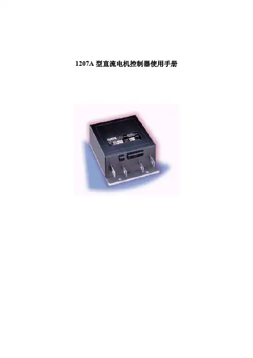
1207A型直流电机控制器使用手册1概述CURTIS PMC 1207A可编程电机速度控制器为各种小型电动车辆提供了高效和易于安装的的控制系统,典型的应用对象为行走式叉车/堆垛车,小型载客车和清洁车等,以微控制器为核心的逻辑部分,配以可靠的MOSFET功率单元,为封装简洁紧凑的1207A控制器提供了大功率输出和先进的性能,可选用手持式编程器使用户能进行快捷、方便地完成参数设定,指导调试及获取故障诊断信息。
同所有CURTIS PMC 电机速度控制器一样,1207A型控制器为车辆的电机驱动速度提供了优异的运动控制,1207A控制器的主要性能包括:◆无级变速和反相制动控制◆大功率MOSFET设计提供高效(减少电机和电池损耗)和无噪声操作◆纯铜功率母线,配以经极化处理接线器传输能量◆采用铝制安装板和注模外壳,具有坚固而保护良好的结构◆过电压和欠电压保护可有效。
◆温度保护和补偿电路提供了低温消减,恒定电流限幅及高温线性回落功能一因而在任何温度条件下都不会发生突然性功率输出中断。
◆智能型手持编程器(选用件)提供了一套完整的参数设定和功能设定◆控制器及其它系统部件的诊断与测试信息,既能够通过车辆上的控制器获得,也可通过编程器获得◆硬件电路和软件对调速器电路, MOSFET驱动电路,MOSFET晶体管,接触器驱动器和接触器进行故障检测---确保控制器满足欧洲经济共同体(EEC)所规定的故障检测要求。
◆输入顺序选择包括空档起动和SRO◆微处理器控制的接触器动作顺序提供了真正的无电弧接触器开闭◆平滑的, 可控的反相制动—可变方式(与调速器位置相关)或固定的反相电流限幅方式◆空挡制动功能。
◆双模式运行可使车辆在不同环境下有不同的运行特性。
◆单信号输入方式的紧急反向功能(凸键开关)◆防后滑功能提供了满功率斜坡起动◆简洁的接触器和开关接线,带有短路和开路监测的线圈驱动器确保了安全操作。
◆灵活的调速器电路能够适应各种类型的调速器:5000-0欧姆,0-5000欧姆,0-5伏,3线电位器和各种电子调速器熟悉CURTIS PMC控制器会帮助您正确地安装和使用它。

双电机调速技术说明书小组成员:XXX XXX XXX XXX随着现代化步伐的加快,人们生活水平的不断提高,对自动化的需求也越来越高,直流电机和步进电机的应用领域也不断扩大。
本设计的功能比直流电机强大,我们既可以把此设计用于教学也可作为需要同步的两个物体的底层设计。
工作原理:本设计主要是实现直流电机和步进电机同步调速,就是将步进电机的速度设为参照,然后执行利用直流电机调速,通过PID控制算法使得直流电机跟着步进电机同步随动。
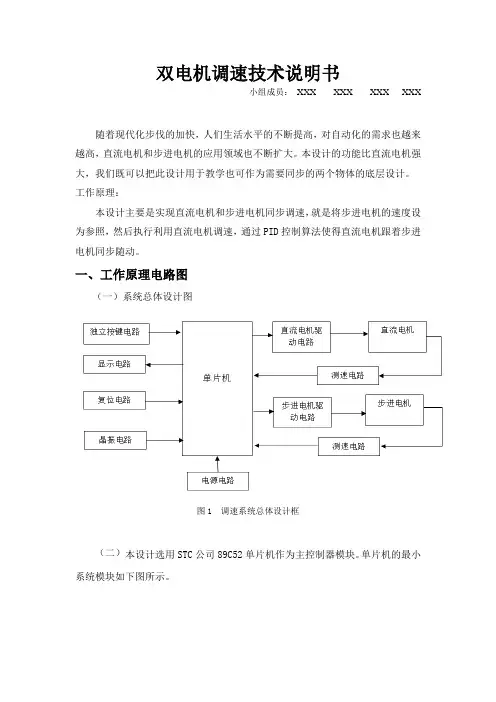
一、工作原理电路图(一)系统总体设计图图1 调速系统总体设计框(二)本设计选用STC公司89C52单片机作为主控制器模块。
单片机的最小系统模块如下图所示。
图2 单片机的最小系统(三)本设计采用目前市场上较容易买到的L298直流或步进电机驱动芯片,它采用单片集成塑装,是一个高电压、大电流全双桥驱动器,由标准的TTL电平控制。
直流驱动模块电路如图所示。
图3 直流驱动模块电路表1 L298对直流电机控制的逻辑真值表输入输出Ven=H Ven=H Ven=H C=H;D=L 正转C=L;D=H 反转C=D 制动Ven=L C,D不确定没有输出,电机不工作(四)本设计中步进电机驱动部分采用专用电机驱动芯片TB6560对电机进行驱动。
步进电机的驱动模块如下图所示:图4 步进电机的驱动模块表2 转矩设定输入TQ1和转矩设定输入TQ2工作电流选择TQ2 TQ2 电流值L L 100%L H 75%H L 50%H H 20%表3 细分方式的选择M2 M10 0 整步0 1 二分之一细分1 0 十六分之一细分1 1 八分之一细分表4 衰减方式PFD2 PFD10 0 快衰减0 1 百分之二十快衰减1 0 百分一五十快衰减1 1 慢衰减(五)1602显示电路设计中显示模块采用LCD1602液晶同时显示步进电机和直流电机的速度,以及步进电机的脉冲光和直流电机的PWM。
其硬件电路实现如图所示:图5 1602显示电路(五)设计中的键盘模块有四个弹性按键,采用高电平输入方式进行信号的输入,按键控制电路如图所示:图6 按键控制电路(六)转速检测电路如图所示:图7 转速检测电路二、电路板的制作工艺(一)电路板的制作过程1.根据电路功能需要设计原理图。
Z771.08/01 版本2C135-8.83/1.3单抽汽双缸双排汽凝汽式汽轮机调节系统说明书南京汽轮电机(集团)有限责任公司编制张琦2008.4 校对汤继星2008.4 审核张静2008.4 会签标准审查郝思军2008.4 审定马艳增2008.4 批准目次1 引言 .................................................. 错误!未定义书签。
2 调节保安系统的主要技术规范 ............................ 错误!未定义书签。
3 供油系统 .............................................. 错误!未定义书签。
4 保安系统 .............................................. 错误!未定义书签。
5 保安系统的调整与试验 .................................. 错误!未定义书签。
1 引言本说明书为C135-8.83/1.3型100MW单抽汽双缸双排汽凝汽式汽轮机调节保安系统的安装,调试以及日后的使用维护和检修提供必要的依据。
本说明书分别列出了调节(控制)、保安、供油及热工系统的主要技术规范。
在使用说明书时,还需要随时参考本机组的其它有关文件和图纸,特别是与调节系统有关的系统总图及相关部套图纸。
2 调节保安系统的主要技术规范3 供油系统润滑油系统的作用是向机组各轴承提供润滑油和向保安系统提供压力油,同时还向盘车装置和顶轴装置供油。
油系统采用的工质为L-TSA46或L-TSA32透平油,透平油质量必须符合GB/T7596-2000《电厂用运行中汽轮机油质量标准》的要求。
本系统采用传统的汽轮机转子直接驱动的主油泵------注油器供油线,主油泵出口的压力油驱动注油器投入工作,润滑油系统主要用于向汽轮发电机组各轴承提供润滑油,向调节保安部套提供压力油,向顶轴装置中的油泵提供充足的油源。
RoboClaw 2x7A, 34VDC Dual Channel Brushed DC Motor ControllerData Sheet Version 2.3Feature Overview:• 7.5 Amps Continuous Per Channel• 15 Amps Peak Per Channel• Channel Bridging Supported• Dual Quadrature Decoding• 9.8 million PPS Decoding• Multimode Interface• TTL Serial• USB Port• Analog Interface• R/C Input Control• Limit, Home and E-Stops• Up to 34VDC Operation• Air Cooled• 3.3v Compliant Control Outputs• 5v Tolerant Control Inputs• Programmable Current Limiting• Programmable Voltage Clamping• Closed and Open Loop Operation• Auto Tuning PID Feature• Mixed Control Modes• Data Logging• Diagnostic LEDs• Field Firmware Updates• Regulated 5VDC, 1A User Available Output• Over Voltage and Under Voltage Protection• Easy Tuning, Monitor and Setup with PC utilityDevice OverviewThe RoboClaw is an intelligent, high performance motor controller designed to control dual brushed DC motors. It can be controlled from USB, RC radio, PWM, TTL serial, analog and microcontrollers such as an Arduino or Raspberry Pi.RoboClaw automatically supports 3.3V or 5V logic levels, travel limit switches, home switches, emergency stop switches, power supplies, braking systems and contactors. A built-in switching mode BEC supplies 5VDC at up to 1 Amp for powering user devices. In addition power supplies can be utilized by enabling the built in voltage clamping control feature.A wide variety of feedback sensors are supported. This includes quadrature encoders, potentiometers and absoluteencoders which can be easily configured using the available auto tune function. With sensors, two brushed DCmotors can be controlled in closed loop mode allowing precise control over position and speed. With the ability to use potentiometers, servo systems can be created and controlled from any of RoboClaw’s interface modes.For greater control, built-in commands are available for controlling acceleration, deceleration, distance, speed, current sense, voltage limits and more. In addition, RC and analog modes can be configured by user defined settings to control acceleration and deceleration rates.RoboClaw incorporates multiple protection features including temperature, current, over voltage and under voltage limits.The protection features are self monitoring and protect RoboClaw from damage in any operating condition. User definable settings such as maximum current limit, maximum and minimum battery voltages are provided for more refined control.RoboClaw’s regenerative capabilities will charge a supply battery during slow down or breaking. It’s advance circuitry can change direction during full throttle without damage! RoboClaw also incorporates a LiPo cutoff mode to prevent battery damage.Multimode InterfaceRoboClaw’s I/O are voltage protected and can handle up to 5VDC. The I/O only output a high of 3.3V. This allows RoboClaw to be interfaced to 5V or 3V logic easily with no translation circuits required. RoboClaw can be connected directly to a Raspberry Pi or Arduino. All of RoboClaw’s inputs are internally pulled-up to prevent false triggers. Inputs can also be configured using the Motion Studio application.User Regulated Power OutputRoboClaw provides regulated power (BEC) for user devices. A high efficiency switching regulator supplies 5VDC at up to1 Amp. This voltage can be used to power external sensors, encoders, MCUs and other electronics. The regulated userpower is automatically current limited and thermally protected.Main BatteryThe peak operational input voltage depending on the model can be up to 34VDC, 60VDC or 80VDC. The modelsmaximum input voltage can not be exceeded. If the maximum voltage is exceed the motors will be disabled. Fully charged batteries maximum voltage must be taken into account when in use. RoboClaw is a regenerative motor controller. During regeneration, voltages can peak over the maximum rated voltage in which RoboClaw is designed to handle these over voltage spikes by braking the motors.Logic BatteryRoboClaw accepts a logic battery. The logic battery is also known as a backup battery. The user regulated power output (BEC) is by default powered from the main battery, unless a logic battery is detected. The logic battery source is coupled to the main battery through an on board automatic switch. If the main battery voltage drops below the logic battery input level, the logic circuit and user regulated power output will be drawn from the logic battery.SoftwareRoboClaw can be easily configured using the Motion Studio software tool. The Windows based application enables users to quickly configure RoboClaw. The software can be used during run time to monitor and control several operational parameters. Motion studio is available from the website. It can also be found in the Downloads section of the Basicmicro website or listed under the Download tabs on the production page.User ManualThis data sheet only covers model specific information and basic wiring. To properly setup and use RoboClaw refer to the RoboClaw User Manual available for download from .CoolingRoboClaw will generate heat. The maximum current ratings can only be achieved and maintained with adequate heat dissipation. The motor controller should be mounted so that sufficient airflow is provided. Which will dissipate the heat away from the motor controller during operation. Some models of RoboClaw include a built-in automatic cooling fan controller, which can be used to help maintain continuous currents under extreme conditions.Emergency StopThe motor controller should be wired using an external contactor, relay or high amperage mechanical switch to control the main power input. A second power source should be used to power the logic section in situations where the main power will be under heavy load. Voltage drops can occur from constant full load or high speed direction changes. Voltage drop can cause logic brown outs if only a main battery is used without a logic battery.USBThe motor controllers USB port should be used for configuration and debugging. The USB protocol is not designed for electrically noisy environments. The USB port will likely disconnect and not automatically recover during operation in electrically noisy environments. To recover from a dropped USB port, the motor controllers USB cable may require being unplugged and re-plugged in. The TTL serial control should be the preferred method of control in electrically noisy environments.Firmware UpdatesFirmware updates will be made available to add new features or resolve any technical issue. Before using RoboClaw for the first time it is recommended to update to the latest firmware. Download and install Motion Studio. Refer to the RoboClaw User Manual or Application Notes for additional information on updating the RoboClaw firmware.Hardware Overview:Control InterfaceThe RoboClaw uses standard male pin headers with 0.100” (2.54mm) spacing. The pin headers are ideal for use withstandard servo cables and other popular interface connectors. The table below list the pins and their respective functions. All pins are 5V tolerant and output 3.3V for compatibility with processor such as Raspberry Pi and Arduino. R/C pulse input, Analog and TTL can be generated from any microcontroller such as a Arduino or Raspberry Pi. The R/C Pulse input pins can also be driven by any standard R/C radio receiver . There are several user configurable options available. Toconfigure RoboClaw, install Motion Studio and connect it to an available USB port.Logic Battery (LB IN)The logic circuit of RoboClaw can be powered from a secondary battery wired to LB IN. A logic battery will prevent brownouts when the main battery is low or under heavy load. The positive (+) terminal is located at the board edge and ground (-) is the inside pin closest to the heatsink.Encoder Power (+ / -)The pins labeled + and - are the source power pins for encoders. The positive (+) is located at the board edge and supplies +5VDC. The ground (-) pin is near the heatsink. On RoboClaws with screw terminals, power for the encoders can be supplied by the 5VDC and GND on the main screw terminal.Encoder Inputs (1A / 1B / 2A / 2B)The encoders inputs are labeled EN1 and EN2. EN1 is for encoder 1 and EN2 is for encoder 2 which also correspond to motor channel 1 and motor channel 2. Quadrature encoder inputs are typically labeled 1A, 1B, 2A and 2B. ChannelA of both EN1 and EN2 are located at the board edge on the pin header. ChannelB pins are located near the heatsinkon the pin header. Quadrature encoders are directional. When connecting encoders make sure the leading channel for the direction of rotation is connected to A. If one encoder is backwards to the other you will have one internal counter counting up and the other counting down. Use Motion Studio to determine the encoders direction relative to the motors rotation. Encoder channels A and B can be swapped in software using Motion Studio to avoid re-wiring the encoder or motor.Control Inputs (S1 / S2 / S3 / S4 /S5)S1, S2, S3, S4 and S5 are configured for standard servo style headers I/O (except on ST models), +5V and GND. S1 and S2 are the control inputs for serial, analog and RC modes. S3 can be used as a flip switch input, when in RC or Analog modes. In serial mode S3, S4 and S5 can be used as emergency stops inputs or as voltage clamping control outputs.When configured as E-Stop inputs, they are active when pulled low. All I/O have internal pull-ups to prevent accidental triggers when left floating. S4 and S5 can be configured as home switch and limit switch inputs. The pins closest to the board edge are the I/0s, center pin is the +5V and the inside pins are ground. Some RC receivers have their own supply and will conflict with the RoboClaw’s 5v logic supply. It may be necessary to remove the +5V pin from the RC receivers cable in those situations.Cooling Fan ControlThe cooling fan control will automatically turn on and off a fan based on RoboClaws temperature. The fan will turn on when the board temperature reaches 45°C and will automatically turn off when the board temperature falls below 35°C.The fan control circuit can power a 5VDC fan at up to 230mA. A wide range of fans can be used. The CFM rating of the fan will determine how effective the fan is at cooling. A tested fan is available from DigiKey under part number:259-1577-ND. However any fan can be used provided it meets the electrical specifications outlined above.Main Battery Screw TerminalsThe main power input can be from 6VDC to 34VDC on a standard RoboClaw and 10.5VDC to 60VDC or 80VDC on an HV (High Voltage) RoboClaw. The connections are marked + and - on the main screw terminal. The plus (+) symbol marks the positive terminal and the negative (-) marks the negative terminal. The main battery wires should be as short as possible.Do not reverse main battery wires or damage will occur.DisconnectThe main battery should include a quick disconnect in case of a run away situation and power needs to be cut. The switch must be rated to handle the maximum current and voltage from the battery. Total current will vary depending on the type of motors used. A common solution would be an inexpensive contactor which can be sourced from sites like Ebay.A power diode rated for approximately 2 to 10 Amps should be placed across the switch/contactor to provide a return tothe battery when power is disconnected. The diode will provide the regenerative power a place to go even if the switch is open.Motor Screw TerminalsThe motor screw terminals are marked with M1A / M1B for channel 1 and M2A / M2B for channel 2. For a typical differential drive robot the wiring of one motor should be reversed from the other. The motor and battery wires should be as short as possible. Long wires can increase the inductance and therefore increase potentially harmful voltage spikes.Control ModesRoboClaw has 4 main functional control modes explained below. Each mode has several configuration options. The modes can be configured using Motion Studio or the built-in buttons. Refer to the RoboClaw User Manual for installation and setup instructions.RCUsing RC mode RoboClaw can be controlled from any hobby RC radio system. RC input mode also allows low powered microcontrollers such as a Basic Stamp to control RoboClaw. Servo pulse inputs are used to control the direction and speed. Very similar to how a regular servo is controlled. Encoders are supported in RC mode, refer to the RoboClaw user manual for setup instructions.AnalogAnalog mode uses an analog signal from 0V to 2V to control the speed and direction of each motor. RoboClaw can be controlled using a potentiometer or filtered PWM from a microcontroller. Analog mode is ideal for interfacing RoboClaw with joystick positioning systems or other non microcontroller interfacing hardware. Encoders are supported in Analog mode, refer to the RoboClaw user manual for setup instructions.Simple SerialIn simple serial mode RoboClaw expects TTL level RS-232 serial data to control direction and speed of each motor.Simple serial is typically used to control RoboClaw from a microcontroller or PC. If using a PC, a MAX232 or an equivalent level converter circuit must be used since RoboClaw only works with TTL level inputs. Simple serial includes a slave select mode which allows multiple RoboClaws to be controlled from a signal RS-232 port (PC or microcontroller). Simple serial is a one way format, RoboClaw can only receive data. Encoders are not supported in Simple Serial mode.Packet SerialIn packet serial mode RoboClaw expects TTL level RS-232 serial data to control direction and speed of each motor. Packet serial is typically used to control RoboClaw from a microcontroller or PC. If using a PC a MAX232 or an equivalent level converter circuit must be used since RoboClaw only works with TTL level input. In packet serial mode each RoboClaw is assigned a unique address. There are 8 addresses available. This means up to 8 RoboClaws can be on the same serial port. Encoders are supported in Packet Serial mode, refer to the RoboClaw user manual for setup instructions.USB ControlUSB can be used in any mode. When RoboClaw is in packet serial mode and another device, such as an Arduino, is connected commands from the USB and Arduino will be executed and can potentially override one another. However if RoboClaw is not in packet serial mode, motor movement commands will be overiden by Analog or RC pulse input. USB packet serial commands can then only be used to read status information and set configuration settings.There are several wiring configurations for RoboClaw. Each configuration will have unique wiring requirements to ensure safe and reliable operation. The diagram below illustrates a very basic wiring configuration used in a small motor system where safety concerns are minimal. This is the most basic wiring configuration possible. All uses of RoboClaw should include some kind of main battery shut off switch, even when safety concerns are minimal. Never underestimate a system with movement when an uncontrolled situation arises.In addition, RoboClaw is a regenerative motor controller. If the motors are moved when the system is off, it could cause potential erratic behavior due to the regenerative voltages powering the system. The regenerative voltages can cause problems if a power supply is used for main power. A voltage clamping circuit is recommended to dump the excessive voltages. See the RoboClaw user manual or Application Notes for voltage clamping setup and wiring diagrams.R/C ModeThe below wiring diagram is very basic and for use with R/C mode. R/C mode can be used when pairing RoboClaw with a standard R/C receiver. R/C mode can also be used with a microcontroller and using servo pulses to control RoboClaw. The RoboClaw supplies power to the R/C system. If the R/C receiver used, has its own power the 5V pin on the 3 pin header must be remove otherwise it will interfere with RoboClaw’s BEC.In all system with movement, safety is a concern. This concern is amplified when dealing with higher voltages. The wiring diagram below illustrates a properly wired system. An external main power cut off is required (SW1). The external cut off can consist of a high amperage mechanical switch or a contactor.When the RoboClaw is switched off or a fuse is blown, a high current diode (D1) is required to create a return path to the battery for potential regenerative voltages. In addition a pre-charge resistor (R1) is required to reduce the high inrush currents to charge the on board capacitors. A pre-charge resistor (R1) should be around 1K, 1/2Watt for a 60VDC motor controller which will give a pre-charge time of about 15 seconds. A lower resistances can be used with lower voltages to decrease the pre-charge time.Closed Loop ModeA wide range of sensors are supported for closed loop operation. RoboClaw supports dual quadrature encoders (up to9.8 million PPS), absolute encoders, potentiometers and hall effect sensors. The wiring diagram below is an exampleof closed loop mode using quadrature encoders. Quadrature encoders are directional. RoboClaw’s internal counters will increment for clockwise rotation (CW) and decrement for counter clockwise rotation (CCW). When wiring encoders A andB channels it is important they are wired to match the direction of the motor. If the encoder is wired in reverse it cancause a run away condition. All motor and encoder combinations will need to be tuned (see the RoboClaw user manual).Logic BatteryAn optional logic battery is supported. Under heavy loads the main power can suffer voltage drops, causing potential logic brown outs which may result in uncontrolled behavior . A separate power source for the motor controllers logic circuit, will remedy potential problems from main power voltage drops. The logic battery maximum input voltage is34VDC with a minimum input voltage of 6VDC. The 5V regulated user output is supplied by the secondary logic battery if supplied. The mAh of the logic battery should be determined based on the load of attached devices powered by the regulated 5V user output.Logic Battery JumperThe configuration below utilizes a logic battery. Older models of RoboClaw have a logic battery jumper . On models where the LB-MB header is present the jumper must be removed when using a separate logic battery. If the header for LB-MB is not present, then the RoboClaw will automatically set the logic battery power source.R1D1Bridging ChannelsRoboClaws dual channels can be bridge to run as one channel, effectively doubling its current capability for one motor.Damage will result if RoboClaw is not set to bridged channel mode before wiring. Download and install Motion Studio.Connect the motor controller to the computer using an available USB port. Run Motion Studio and in general settings check the option to combine channels. Then click “Write Settings” in the device menu. When operating in bridged mode the total peak current output is combined from both channels. Each channel will indicate the amount of current being drawn for that channel. The peak current run time is dependant on heat build up. Adequate cooling must be maintained.For more information see the RoboClaw user manual.Bridged Channel WiringWhen bridged channel mode is active the internal driver scheme for the output stage is modified. The output leads must be wired correctly or damage will result. One side of the motor is connected to M1A and M2B. The other side of the motor is then connected to M1B and to M2A.DimensionsNotes:1. Peak current is automatically reduced to the typical current limit as temperature approaches 85°C.2. Current is limited by maximum temperature. Starting at 85°C, the current limit is reduced on a slope with a maximumtemperature of 100°C, which will reduce the current to 0 amps. Current ratings are based on ambient temperature of 25°C.3. RS232 format is 8Bit, No Parity and 1 Stop bit.4. Condensing humidity will damage the motor controller.WarrantyBasicmicro warranties its products against defects in material and workmanship for a period of 1 year. If a defect is discovered, Basicmicro will, at our sole discretion, repair, replace, or refund the purchase price of the product in question.*******************************.Noreturnswillbeacceptedwithouttheproperauthorization.Copyrights and TrademarksCopyright© 2015 by Basicmicro, Inc. All rights reserved. All referenced trademarks mentioned are registered trademarks of their respective holders.DisclaimerBasicmicro cannot be held responsible for any incidental or consequential damages resulting from use of products manufactured or sold by Basicmicro or its distributors. No products from Basicmicro should be used in any medical devices and/or medical situations. No product should be used in any life support situations.ContactsEmail:********************Techsupport:**********************Web: Discussion ListA web based discussion board is maintained at Technical Support*******************************************************************,byopeningasupportticketontheIon Motion Control website or by calling 800-535-9161 during normal operating hours. All email will be answered within 48 hours.。
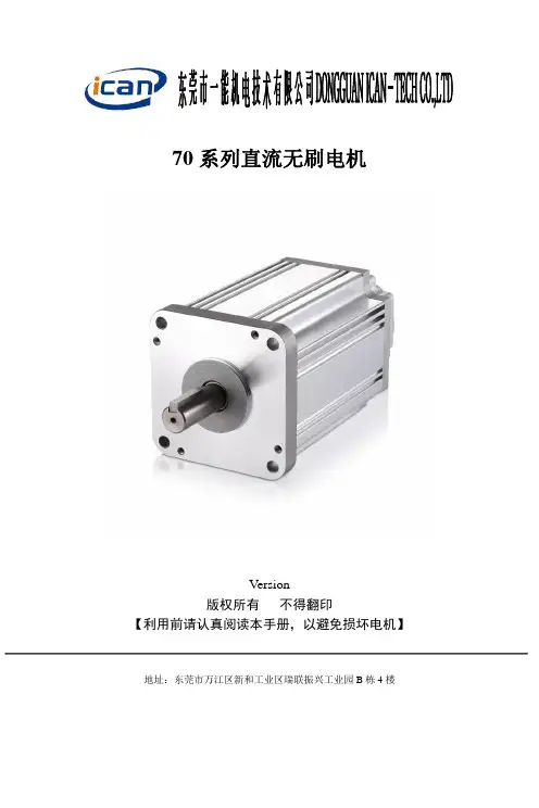
70系列直流无刷电机Version版权所有不得翻印【利用前请认真阅读本手册,以避免损坏电机】地址:东莞市万江区新和工业区瑞联振兴工业园B栋4楼70系列直流无刷电机利用手册70系列直流无刷电机一、产品简介概述70系列直流无刷电机,相较于市场中现有的产品,因东莞市一能机电技术设计革新使70无刷电机具有噪音更低,振动更小和工作寿命更长的优势。
产品能够普遍应用与工业自动化、泵阀、太阳能设备等。
产品特点驱动电压:DC48V基座号:70方形功率:320W调速范围:≤3500rpm适配驱动器:BLD300B参数规格型号输出功率(W)电机电压(VDC)转速(RPM)额定扭矩(Nm)机身长度(mm)重量(kg)70BLF-3230LBB 320 48 3000 120机械尺寸驱动器连接方式网址:70系列直流无刷电机利用手册力矩曲线图注意事项一不可拎着电机引线去拿70系列直流无刷电机二在70系列直流无刷电机通电的状态下不可插拨插头三请不要使70无刷电机落地,和碰撞电机,有此类情形发生的话,即便那时能够利用但70无刷电机的质量将不能取得保证四请顾客方对70直流无刷电机在实际装配的状态进行确认,验证明际利历时的适用性五 70直流无刷电机对过电压、过热、逆转、外部噪音等没有爱惜装置利历时请注意六70直流无刷电机分解后不可在组装利用七本公司对70直流无刷电机在实际利用中、关于利用方式所涉及的专利问题不负任何责任配套产品网址:70系列直流无刷电机利用手册产品保修条款一、一年保修期本公司对该产品的元器件和生产进程进行严格治理,从发货日起为客户提供一年的质保。
在保修期内本公司为有缺点的产品提供免费维修效劳。
二、不属保修之列1、不适当的接线,如电源正负极接反和带电拨插2、未经许可擅自更改内部器件,或撕掉易碎QC凭条的;3、超电器参数要求利用;4、极为特殊的应用环境,如极高温度或极度潮湿的环境等。
三、维修流程如需维修产品,将按下述流程处置:1、发货前请致电本公司窗口效劳人员获取返修许可号码2、随货周围寄书面说明,说明返修驱动器的故障现象;故障发生时所利用的电压、电流和利用环境等情形,联系人姓名、号及邮寄地址信息。
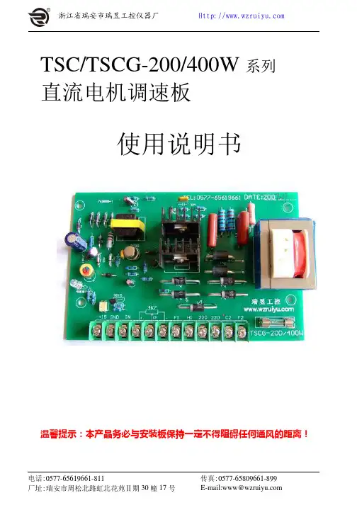
TSC/TSCG-200/400W系列直流电机调速板使用说明书温馨提示:本产品务必与安装板保持一定不得阻碍任何通风的距离!一、简介TSC/TSCG-200/400W系列可控硅控制直流电机调速板具有体积小、安装方便、调速精度高、价格低等优点,广泛使用于电线、电缆、轻工、纺织、造纸、化工、印染、冶金、橡塑、拉丝、挤出机械、医疗器械、食品生产、印刷包装等各种行业,并可与永磁、他激、并激、串激直流电机配套使用。
对小型直流电机电枢供电,使直流电机实现恒转矩无级调速。
本装置主电路采用单相桥式半控电路,并带有电压负反馈等环节,提高了调速精度,控制电路采用单结晶体管触发,电路线路简单,工作稳定可靠,并且温度补偿性能稳定。
可外接控制包括:位移控制器、光电开关和位移传感器。
二、参数1、长期连续工作制2、正常工作电压:220V(±10%)3、输出电流:2.5A4、调速范围:1:105、静态精度:5%6、适配电机功率:200W—400W7、电枢输出电压:DC0—220V8、励磁输出电压:DC200V/1A9、外形尺寸(长×宽×高):162×100×55mm10、接线方式:端子式三、安装须知1、用户在使用本产品之前,应仔细阅读说明书。
2、请不要安装在高温、高湿度的环境中。
3、请不要安装在木材等易燃性的材料上。
4、请不要安装在高振动的机器设备上。
5、请不要安装在有油雾、灰尘、有易燃气体的环境中。
6、控制板安装时务必与导电体间保持适当空间,以免控制板短路等原因损毁。
7、在上电以后以及断电后十分钟内,请勿接触控制仪/板上导体部分,以免触电。
(注1:)只有合格的专业人员才可以实施安装、配线、拆卸及保养。
(注2:)请遵守安装须知,若未依上述规定安装,而导致控制板损毁或发生危险事件,本厂不负任何责任。
在安装过程中有任何问题,欢迎来电咨询。
四、特点1、用可控硅触发实现无级调速。
2、引入电压负反馈技术使速度更平稳。

Lab-bench use is enhanced by the fan-speed control, which minimizes acoustic noise. The extremely low ripple and noise helps the built-in measurement system make extreme-ly accurate current and voltage measurements.Power Products Catalog 2002-2003 For more detailed specifications see the product manual at /find/power39Increase test throughput with fast up and down programming 6671A - 6675A6671A 6672A 6673A 6674A 6675A1111Yes Yes Yes Yes 0 to 8 V 0 to 20 V 0 to 35 V 0 to 60 V 0 to 120 V 0 to 220 A 0 to 100 A 0 to 60 A 0 to 35 A 0 to 18 A change in load from 100% to 50% or 50% to 100% of the output current rating of the supplyAverage resolution Voltage 2 mV 5 mV 10 mV 15 mV 30 mV Current 55 mA 25 mA 15 mA 8.75 mA 4.5 mA OVP15 mV35 mV65 mV100 mV215 mVOutput Voltage programming response time*(excluding command 30 ms 60 ms 130 ms 130 ms 195 msprocessing time)*Full load programming rise/fall time (10% to 90% or 90% to 10%) with full resistive load equal to rated outputvoltage/rated output current.See page 102 for more details Weight:Net, 28.2 kg (62 lbs); shipping, 31.8 kg (70 lbs) Warranty Period:Three years Full load programming rise/fall time (10% to 90% or 90% to 10%) with full resistive load equal to rated output voltage/rated output current.Power Products Catalog 2002-2003 For more detailed specifications see the product manual at /find/power40voltage/rated output current.Power Products Catalog 2002-2003 For more detailed specifications see the product manual at /find/power41Power Products Catalog 2002-2003 For more detailed specifications see the product manual at /find/power42To see a copy of the user’s guide, please visit our Web site at/find/manualsBy internet, phone, or fax, get assistance with all your test & measurement needs Online assistance:/find/assistPhone or FaxUnited States:(tel)180****4844Canada:(tel)187****4414(fax) (905) 282-6495China:(tel) 800-810-0189(fax) 1-0800-650-0121Europe:(tel) (31 20) 547 2323(fax) (31 20) 547 2390Japan:(tel) (81) 426 56 7832(fax) (81) 426 56 7840Korea:(tel) (82-2) 2004-5004 (fax) (82-2) 2004-5115Latin America:(tel) (305) 269 7500(fax) (305) 269 7599Taiwan:(tel) 080-004-7866 (fax) (886-2) 2545-6723Other Asia Pacific Countries:(tel) (65) 375-8100 (fax) (65) 836-0252Email:*******************Product specifications and descriptions in this document subject to change without notice.Your Requested Excerpt from the Agilent Power Products CatalogThe preceding page(s) are an excerpt from the 2002-2003 Power Products Catalog .We hope that these pages supply the information that you currently need. If you would like to have further information about the extensive selection of Agilent dc power supplies, ac sources, and dc electronic loads, please visit /find/power to print a copy of the complete Power Products catalog, or to request that a copy be sent to you. You will also find a lot of other useful information on this web site.In the full Power Products Catalog, you will find that Agilent offers much more than basic power generation. If you need basic, clean, power for your lab bench,it’s there. But in each product category, we’ve also integrated the capabilities that you need for a complete power solution, including extensive measurement and analysis capabilities.Please give us a call at your local Agilent Technologies sales office, or call a regional office listed below, for assistance in choosing or using Agilent power products.Keep up to date with Agilent’s Test and Measurement Email UpdatesAs an Email Update subscriber, you will receive periodic customized email updates that match the areas of interest that you have specified. Your update will include products and services, applications and support information, events,and promotions. Sign up today at /find/emailupdates . Check off dc power supplies, ac power sources or electronic loads on your registration form, and we will promptly let you know what’s new in power products! Our Privacy Statement at /go/privacy describes our commitment to you regarding your privacy.Agilent Technologies。
重庆赛力盟电机有限责任公司直流电机使用维护说明书1概述直流电机是将直流电能与机械能相互转换的旋转电机,它具有优良的调速特性,调速平滑、方便、范围宽广;它具有过载能力大,能承受频繁的冲击负载;它具有能实现频繁的无级快速起动、制动和反转,能满足各种生产过程自动化系统、不同的特殊运行特点的要求;它广泛用于冶金、矿山、交通运输、纺织、印染、造纸、印刷、水泥、化工、机床、风机等行业。
Z2系列适用于恒速或调速范围不大于2:1的电力拖动系统中,为自扇冷结构。
ZO2系列适用于多尘埃及金属切削等场合,为全封闭结构。
ZT2系列适用于削弱磁场向上恒功率调速,调速范围为1:3及1:4的电力拖动中。
Z2C系列适用于船舶恒速电力拖动系统中,也可作为海洋或内河船舶各种辅机电力拖动和供电电源之用。
Z3系列适用于恒速或转速调节范围不大于3:1的电力拖动系统小,有自扇冷结构和强迫通风两种。
Z4系列采用全迭片结构,适用于静止整流电源供电,具有转动惯量小,有较好的动态性能,为强迫通风结构,也可以用作管道通风或空水冷结构。
ZBL4系列采用全封闭结构,机座带散热片。
适用于多尘埃的场合。
ZSL4系列为自扇冷结构,可弱磁恒功率向上调速,达额定转速的1-2倍。
已生产电机的机座号132——200,共3个机座号。
ZLZ4系列采用全封闭结构,可用于连铸机的传动系统中。
ZZJ-800系列能承受频繁的起动、制动、正反转,过载能力大,用于金属轧机的辅传动机械及冶金起重,有全封闭结构,有强迫通风结构和空水冷结构。
过载能力为3倍左右。
ZZJ-900系列具有ZZJ-800系列的特点,且转动惯量为ZZJ-800系列的60%。
Z系列中型直流电动机可用于普通工业和传动金属轧机及其辅助机械,有强迫通风结构和空水冷结构。
ZSN4系列为水泥回转窖主传动专用直流电机,有强迫通风结构和管道通风结构。
2电机的起运、安装及校正2.1电机的起运2.1.1运输及拆箱时应遵守“小心轻放”、“切勿倒置”等说明。
直流电机使用维护说明书1.安全注意事项任何时候都必须遵守一般的安全规章及本说明书所述的安全预防措施。
在开始前(在开始储存、安装、运行、维护和检查等之前)必须仔细阅读本说明书及其他随机文件,以确保人员及设备安全。
通过对安全使用知识和预防措施的了解,增加对电机安装、运行、维护等方面的认识。
用户应对照合同确认交付的产品是否为订购的产品。
注意不要使用有故障的设备。
有资质的人员才可以从事搬运、安装、管线的连接、设备运行、设备维护保养和常规检查工作。
忽视这一点可能会引起伤害、触电、损坏或火灾等事故。
1.1 运输及储存·确认包装的方式。
拆开包装时,注意钉子等。
否则将导致伤害。
·运输期间,要特别小心,设备摔落或过度倾斜均可能导致危险。
·起吊电机时,请使用起吊电机本体的吊环螺栓或吊攀进行吊运。
·对于整体装箱的电机,须按照标识的起吊位置进行起吊。
·当电机的重量超过用户起吊工具允许起吊的重量时,决不可用来起吊电机。
在起吊前,必须从铭牌、包装或外形图上查看电机的重量。
否则将导致起吊工具的断裂、电机倾斜摔落、人员伤害和设备损坏等事故。
1.2 安装·管路和线路连接中,在电缆连接时,必须严格按所供资料进行操作。
·进行布线时,不得有短路或端子在盒内接地的危险存在。
忽视这一点会引起触电或火灾,或将引起接线盒的损坏。
·安装和调整时,不要用力弯曲、拉引电力电缆或电机引线,这样将会产生隐患。
·要保持接地端子始终接地,否则会引起触电。
·接线盒盖打开后不可运行。
工作完毕后,接线盒盖装于原处。
疏忽这一操作会引起触电。
·不要在电机周围堆放易燃物品,否则会引起火灾事故。
·装好盖板等,使旋转的部件不至于被触及。
否则将导致伤害。
·当电机单独运行时,应将装在轴上的键临时拆去。
否则会引起伤害。
·电机接线前,确认其旋转方向,忽视这一过程会导致电机损坏。
M97系列可编程直流电子负载用户使用手册适用型号M9711/M9712/M9712B/M9712C/M9712B30Maynuo Electronics 2009II版本号:V1.1南京美尔诺电子有限公司版权所有目录第一章简介 (1)第二章技术规格 (2)2.1主要技术规格 (2)2.2电子负载尺寸图 (6)第三章快速入门 (7)3.1开机自检 (7)3.2如果负载不能启动 (8)3.3前面板和后面板介绍 (9)3.4键盘说明 (10)3.5菜单操作 (11)第四章面板操作 (16)4.1基本操作模式 (16)4.1.1定电流操作模式(CC) (16)4.1.1.1标准定电流模式 (16)4.1.1.2加载卸载定电流模式 (17)4.1.1.3软启动定电流模式 (18)4.1.1.4定电流转定电压模式 (19)4.1.2定电阻操作模式(CR) (19)4.1.2.1 标准定电阻模式 (20)4.1.2.2 加载卸载定电阻模式 (20)4.1.2.3定电阻转定电压模式 (21)4.1.3定电压操作模式(CV) (21)4.1.3.1标准定电压模式 (22)4.1.3.2加载卸载定电压模式 (22)4.1.3.3软启动定电压模式 (23)4.1.4定功率操作模式(CW) (24)4.1.4.1标准定功率模式 (24)4.1.4.2加载卸载定功率模式 (25)4.2动态测试操作 (26)4.2.1连续模式(CONTINUOUS ) (26)4.2.2脉冲模式(PULSE) (26)4.2.3触发模式(TRIGGER) (27)4.2.4 动态测试参数设置 (27)4.2.5波形控制 (28)4.2.5.1方波 (28)4.2.5.2三角波 (28)4.2.5.3梯形波 (28)I4.2.6 触发控制 (28)4.2.7 LIST功能 (29)4.2.7.1.编辑LIST列表 (29)4.2.7.2执行LIST功能 (30)4.2.8 自动测试功能 (30)4.2.8.1编辑自动测试列表 (31)4.2.8.2设置自动测试触发输出方式 (32)4.2.8.3执行自动测试功能 (33)4.3输入控制 (33)4.3.1 短路操作(SHORT) (33)4.3.2 输入开关操作 (33)4.4电子负载可操作范围 (34)4.5保护功能 (34)4.5.1 过电压保护(OV) (34)4.5.2 过电流保护(OC) (35)4.5.3 过功率保护(OW) (35)4.5.4 输入极性反接 (36)4.5.5 过温度保护(OH) (36)4.6远端测试功能 (36)4.7蓄电池放电测试操作 (36)4.8快捷方式功能说明 (38)4.9通讯协议 (39)4.9.1 概述 (39)4.9.2 通讯口DB9的定义 (40)4.9.3 选择通讯波特率 (41)4.9.4 数据 (41)4.9.5功能码 (41)4.9.6 差错校验 (41)4.9.7 完整命令帧解析 (42)4.9.8 线圈与寄存器地址分配 (46)4.9.9 命令寄存器CMD定义 (49)4.9.10常用操作功能说明 (50)4.9.11 通讯线的选择 (56)II第一章简介M97系列产品是美尔诺电子公司设计制造的新一代直流电子负载,采用高性能芯片,高速,高精度设计,提供0.1mV,0.01mA的解析度(基本精度为0.03%,基本电流上升速度2.5A/us), 外观新颖,生产工艺科学严谨,相比同类产品,更具性价比。