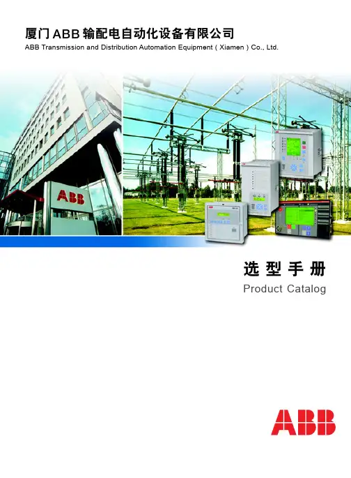
ABB中间继电器
- 格式:pdf
- 大小:1.33 MB
- 文档页数:10
环境条件
型号 环境温度范围
抗震性
标准
型号 产品标准 低压指令
CR-MX...2 300 V AC F 触点与线圈之间 5.8 mm 触点与线圈之间 3.5 mm III 2
1SVR405631R4100
CR-MX024DC2L
24 V DC
1SVR405631R1100
CR-MX048DC2L
48 V DC
1SVR405631R6100
CR-MX110DC2L
110 V DC
1SVR405631R8100
CR-MX024AC2L
24 V AC
1SVR405631R0100
48 V DC
1SVR405631R6000
CR-MX110DC2
110 V DC
1SVR405631R8000
CR-MX024AC2
24 V AC
1SVR405631R0000
CR-MX110AC2
110 V AC
1SVR405631R7000
CR-MX230AC2
230 V AC
1SVR405631R3000
CR-P/M 42B 24-60 V DC
CR-P/M 42BV 24-60 V DC
CR-P/M 42C 110 V DC
CR-P/M 42CV 110 V DC
RC回路 - 滤波和灭弧
CR-P/M 52B 6-24 V AC/DC CR-P/M 52D 24-60 V AC/DC CR-P/M 52C 110-230 V AC/DC
线圈电阻 (20℃时) 160 Ω 650 Ω 2600 Ω 11000 Ω 184 Ω 4550 Ω 14400 Ω
线圈电阻误差
± 10 % ± 10 % ± 15 % ± 15 % ± 10 % ± 15 % ± 15 %
CR-MX...4
11-12/14 21-22/24 31-32/34 41-42/44 继电器, 4 c/o (SPDT)触点
红色, 用于 DC: A1+, A2- 1SVR405654R0000 10 绿色, 用于 DC: A1+, A2- 1SVR405654R1000 10 红色, 用于 DC: A1+, A2- 1SVR405654R4000 10 绿色, 用于 DC: A1+, A2- 1SVR405654R4100 10 红色, 用于 DC: A1+, A2- 1SVR405654R0100 10 绿色, 用于 DC: A1+, A2- 1SVR405654R1100 10
24 V DC
1SVR405633R1100
CR-MX048DC4L
48 V DC
1SVR405633R6100
CR-MX110DC4L
110 V DC
1SVR405633R8100
CR-MX024AC4L
24 V AC
1SVR405633R0100
CR-MX110AC4L
110 V AC
1SVR405633R7100
释放电压
1.2 V DC 2.4 V DC 4.8 V DC 11 V DC 7.2 V AC 36 V AC 72 V AC
CR-MX...2 11-12/14 41-42/44
额定功率
0.9 W 0.9 W 0.9 W 0.9 W 1.2 VA 1.4 VA 1.8 VA
触点数量
触点材料 额定工作电压Ue(IEC/EN 60947 - 1) 最小开关电压 最大开关电压 最小开关电流 额定自由空气发热电流Ith 额定工作电流(IEC/EN 60947-5-1) AC等级(UL508;NEMA ICS-5) DC等级(UL508;NEMA ICS-5) 最小开关功率 最大开关(释放)功率 接触电阻 最大工作频率
产品简介 I 03 2014
控制产品 - 插拔式中间接口继电器 • CR-MX 系列
插拔式中间接口继电器 - CR-MX 系列 产品概述
在电气控制中,可插拔中间接口继电器一 般用于电气隔离驱动、放大和信号匹配, 例如用于PLC、PC或现场总线系统与现场 的传感器/执行器层之间。
ABB新型CR-MX系列中间接口继电器更贴 合通用工业控制实际需求,其安装调试简 便,工作稳定可靠,使用寿命更长。
认证 H UL508
TUV CQC
标记 a CE
2 1SXF110006L2001 | ABB | 插拔式中间接口继电器
2CDC 291 006 S0014
插拔式中间接口继电器 - CR-MX 系列 产品概述
结构
1 底座 2 中间接口继电器 3 金属固定器 4 标识
应用 该接口继电器是电磁式的,主要用于控制单元和现场设备之间,起到电气隔离、电压匹配、噪音抑制和信号放大等作用。 工作模式 当控制电压加在继电器线圈时,继电器的输出触点(NO)吸合;当控制电压失去,输出触点回到初始位置。
CR-MX230AC4L
230 V AC
1SVR405633R3100
中间接口继电器, 不带LED, 2 c/o (SPDT)触点:250 V AC 7A
CR-MX012DC2
12 V DC
1SVR405631R4000
CR-MX024DC2
24 V DC
1SVR405631R1000
CR-MX048DC2
机械寿命 电气寿命
吸合时间 释放时间
继电器, 2 c/o (SPDT)触点 银合金 250 V 6V 250 V AC / 30 V DC 1A 7A 根据需求提供 根据需求提供 根据需求提供 6W AC1(阻性) 1750 VA / 210 W 100 mΩ (1A / 6 V DC) 额定负载 AC1 1200 周次/h 空载 9000 周次/h > 107 周次 电气 AC1(阻性) > 105 周次 cos φ 0.95 25 ms 25 ms
110 V DC
1SVR405633R8000
CR-MX024AC4
24 V AC
1SVR405633R0000
CR-MX110AC4
110 V AC
1SVR405633R7000
CR-MX230AC4
230 V AC
1SVR405633R3000
包装数
10 10 10 10 10 10 10
10 10 10 10 10 10 10
ABB | 插拔式中间接口继电器 | 1SXF110006L2001 3
插拔式中间接口继电器 - CR-MX 系列 订货资料
2CDC 291 008 S0014
型号
额定控制电压 Us
工厂编号
中间接口继电器, 带LED, 2 c/o (SPDT)触点:250 V AC 7A
CR-MX012DC2L
12 V DC
CR-MX110AC2L
110 V AC
1SVR405631R7100
CR-MX230AC2L
230 V AC
1SVR405631R3100
中间接口继电器, 带LED, 4 c/o (SPDT)触点:250 V AC 5A
CR-MX012DC4L
12 V DC
1SVR405633R4100
CR-MX024DC4L
直流线圈
额定控制电压 Us
12 V DC
吸合电压 (23℃时)
9.6 V DC
24 V DC
19.2 V DC
48 V DC
38.4 V DC
110 V DC
88 V DC
交流线圈
24 V AC
19.2 V AC
110 V AC
96 V AC
230 V AC
176 V AC
输出回路
型号 输出回路
最大电压 (55℃时) 13.2 V DC 26.4 V DC 52.8 V DC 121 V DC 26.4 V AC 132 V AC 264 V AC
形式 金属固定器
工厂编号
包装数
1SVR405651R1400 10
1SVR405651R3400 10
工厂编号
包装数
1SVR405659R1100 10
ABB | 插拔式中间接口继电器 | 1SXF110006L2001 5
插拔式中间接口继电器 - CR-MX 系列 技术参数
输入回路 - 线圈侧参数 A1 - A2
2CDC 291 006 S0014
特点 - 标准微型继电器 - 7种不同的额定线圈电压:
DC: 12 V, 24 V, 48 V, 110 V AC: 24 V, 110 V, 230 V - 输出:2 c/o(SPDT)触点(7 A)或4 c/o(SPDT)触点(5 A) - 带或不带LED - 触点材料不含镉 - 在底座上的宽度:27 mm (1.063 in) - 可选配可插拔功能模块
1SVR405656R0000 10 1SVR405656R1000 10 1SVR405656R2000 10
附件 - 底座
型号 CR-M2SFB CR-M4SFB
形式 用于2 c/o (SPDT) 继电器,黑色 用于2或4 c/o (SPDT) 继电器,黑色
连接 叉式螺钉 叉式螺钉
固定器
型号 CR-MH1
1SVR405652R0000 10 1SVR405652R1000 10 1SVR405652R4000 10 1SVR405652R4100 10 1SVR405652R9000 10 1SVR405652R9100 10
1SVR405653R0000 10 1SVR405653R4000 10 1SVR405653R1000 10
2CDC 291 005 S0011
型号 环境温度范围
抗震性
标准
型号 产品标准 低压指令
CR-MX...2 300 V AC F 触点与线圈之间 5.8 mm 触点与线圈之间 3.5 mm III 2
1SVR405631R4100
CR-MX024DC2L
24 V DC
1SVR405631R1100
CR-MX048DC2L
48 V DC
1SVR405631R6100
CR-MX110DC2L
110 V DC
1SVR405631R8100
CR-MX024AC2L
24 V AC
1SVR405631R0100
48 V DC
1SVR405631R6000
CR-MX110DC2
110 V DC
1SVR405631R8000
CR-MX024AC2
24 V AC
1SVR405631R0000
CR-MX110AC2
110 V AC
1SVR405631R7000
CR-MX230AC2
230 V AC
1SVR405631R3000
CR-P/M 42B 24-60 V DC
CR-P/M 42BV 24-60 V DC
CR-P/M 42C 110 V DC
CR-P/M 42CV 110 V DC
RC回路 - 滤波和灭弧
CR-P/M 52B 6-24 V AC/DC CR-P/M 52D 24-60 V AC/DC CR-P/M 52C 110-230 V AC/DC
线圈电阻 (20℃时) 160 Ω 650 Ω 2600 Ω 11000 Ω 184 Ω 4550 Ω 14400 Ω
线圈电阻误差
± 10 % ± 10 % ± 15 % ± 15 % ± 10 % ± 15 % ± 15 %
CR-MX...4
11-12/14 21-22/24 31-32/34 41-42/44 继电器, 4 c/o (SPDT)触点
红色, 用于 DC: A1+, A2- 1SVR405654R0000 10 绿色, 用于 DC: A1+, A2- 1SVR405654R1000 10 红色, 用于 DC: A1+, A2- 1SVR405654R4000 10 绿色, 用于 DC: A1+, A2- 1SVR405654R4100 10 红色, 用于 DC: A1+, A2- 1SVR405654R0100 10 绿色, 用于 DC: A1+, A2- 1SVR405654R1100 10
24 V DC
1SVR405633R1100
CR-MX048DC4L
48 V DC
1SVR405633R6100
CR-MX110DC4L
110 V DC
1SVR405633R8100
CR-MX024AC4L
24 V AC
1SVR405633R0100
CR-MX110AC4L
110 V AC
1SVR405633R7100
释放电压
1.2 V DC 2.4 V DC 4.8 V DC 11 V DC 7.2 V AC 36 V AC 72 V AC
CR-MX...2 11-12/14 41-42/44
额定功率
0.9 W 0.9 W 0.9 W 0.9 W 1.2 VA 1.4 VA 1.8 VA
触点数量
触点材料 额定工作电压Ue(IEC/EN 60947 - 1) 最小开关电压 最大开关电压 最小开关电流 额定自由空气发热电流Ith 额定工作电流(IEC/EN 60947-5-1) AC等级(UL508;NEMA ICS-5) DC等级(UL508;NEMA ICS-5) 最小开关功率 最大开关(释放)功率 接触电阻 最大工作频率
产品简介 I 03 2014
控制产品 - 插拔式中间接口继电器 • CR-MX 系列
插拔式中间接口继电器 - CR-MX 系列 产品概述
在电气控制中,可插拔中间接口继电器一 般用于电气隔离驱动、放大和信号匹配, 例如用于PLC、PC或现场总线系统与现场 的传感器/执行器层之间。
ABB新型CR-MX系列中间接口继电器更贴 合通用工业控制实际需求,其安装调试简 便,工作稳定可靠,使用寿命更长。
认证 H UL508
TUV CQC
标记 a CE
2 1SXF110006L2001 | ABB | 插拔式中间接口继电器
2CDC 291 006 S0014
插拔式中间接口继电器 - CR-MX 系列 产品概述
结构
1 底座 2 中间接口继电器 3 金属固定器 4 标识
应用 该接口继电器是电磁式的,主要用于控制单元和现场设备之间,起到电气隔离、电压匹配、噪音抑制和信号放大等作用。 工作模式 当控制电压加在继电器线圈时,继电器的输出触点(NO)吸合;当控制电压失去,输出触点回到初始位置。
CR-MX230AC4L
230 V AC
1SVR405633R3100
中间接口继电器, 不带LED, 2 c/o (SPDT)触点:250 V AC 7A
CR-MX012DC2
12 V DC
1SVR405631R4000
CR-MX024DC2
24 V DC
1SVR405631R1000
CR-MX048DC2
机械寿命 电气寿命
吸合时间 释放时间
继电器, 2 c/o (SPDT)触点 银合金 250 V 6V 250 V AC / 30 V DC 1A 7A 根据需求提供 根据需求提供 根据需求提供 6W AC1(阻性) 1750 VA / 210 W 100 mΩ (1A / 6 V DC) 额定负载 AC1 1200 周次/h 空载 9000 周次/h > 107 周次 电气 AC1(阻性) > 105 周次 cos φ 0.95 25 ms 25 ms
110 V DC
1SVR405633R8000
CR-MX024AC4
24 V AC
1SVR405633R0000
CR-MX110AC4
110 V AC
1SVR405633R7000
CR-MX230AC4
230 V AC
1SVR405633R3000
包装数
10 10 10 10 10 10 10
10 10 10 10 10 10 10
ABB | 插拔式中间接口继电器 | 1SXF110006L2001 3
插拔式中间接口继电器 - CR-MX 系列 订货资料
2CDC 291 008 S0014
型号
额定控制电压 Us
工厂编号
中间接口继电器, 带LED, 2 c/o (SPDT)触点:250 V AC 7A
CR-MX012DC2L
12 V DC
CR-MX110AC2L
110 V AC
1SVR405631R7100
CR-MX230AC2L
230 V AC
1SVR405631R3100
中间接口继电器, 带LED, 4 c/o (SPDT)触点:250 V AC 5A
CR-MX012DC4L
12 V DC
1SVR405633R4100
CR-MX024DC4L
直流线圈
额定控制电压 Us
12 V DC
吸合电压 (23℃时)
9.6 V DC
24 V DC
19.2 V DC
48 V DC
38.4 V DC
110 V DC
88 V DC
交流线圈
24 V AC
19.2 V AC
110 V AC
96 V AC
230 V AC
176 V AC
输出回路
型号 输出回路
最大电压 (55℃时) 13.2 V DC 26.4 V DC 52.8 V DC 121 V DC 26.4 V AC 132 V AC 264 V AC
形式 金属固定器
工厂编号
包装数
1SVR405651R1400 10
1SVR405651R3400 10
工厂编号
包装数
1SVR405659R1100 10
ABB | 插拔式中间接口继电器 | 1SXF110006L2001 5
插拔式中间接口继电器 - CR-MX 系列 技术参数
输入回路 - 线圈侧参数 A1 - A2
2CDC 291 006 S0014
特点 - 标准微型继电器 - 7种不同的额定线圈电压:
DC: 12 V, 24 V, 48 V, 110 V AC: 24 V, 110 V, 230 V - 输出:2 c/o(SPDT)触点(7 A)或4 c/o(SPDT)触点(5 A) - 带或不带LED - 触点材料不含镉 - 在底座上的宽度:27 mm (1.063 in) - 可选配可插拔功能模块
1SVR405656R0000 10 1SVR405656R1000 10 1SVR405656R2000 10
附件 - 底座
型号 CR-M2SFB CR-M4SFB
形式 用于2 c/o (SPDT) 继电器,黑色 用于2或4 c/o (SPDT) 继电器,黑色
连接 叉式螺钉 叉式螺钉
固定器
型号 CR-MH1
1SVR405652R0000 10 1SVR405652R1000 10 1SVR405652R4000 10 1SVR405652R4100 10 1SVR405652R9000 10 1SVR405652R9100 10
1SVR405653R0000 10 1SVR405653R4000 10 1SVR405653R1000 10
2CDC 291 005 S0011