BPE手册
- 格式:pdf
- 大小:4.11 MB
- 文档页数:8
目标分解在管理中,关键绩效指标将根据管理层级层层分解在东风小康,我们将指标体系分为一级、二级、三级。
其中:一级指标:是指公司确定下达到各单位(工厂)的指标二级指标:是指各单位(工厂)确定下达到各部门的指标三级指标:是指各部门内部分解指标目标分解(范例)不要陷入指标的泥潭小朋友打酱油妈妈叫儿子去买瓶酱油回来结果小朋友贪玩,半个小时才将酱油买回来妈妈很生气,于是要求儿子下次买酱油不能超过10分钟第二次,小朋友图省事,在楼下小卖部花了十块钱买酱油妈妈又很生气,说太贵了,于是要求儿子下次买酱油不能超过5元钱第三次,小朋友兴冲冲按照妈妈的要求买到了酱油,一不小心,摔了一跤,结果摔坏了手臂,酱油也撒了一地妈妈知道后又很生气,教训儿子下次买酱油一定要注意安全小朋友认识到,妈妈要他安全、快捷、便宜地买回酱油下次妈妈再叫他打酱油时,他开始注意妈妈的嘱咐,结果小朋友过于注重价格,买了一瓶劣质酱油回来妈妈一看,这种酱油炒菜味道不好,对儿子说,下次买酱油要挑牌子小朋友迷糊了,便宜没好货,牌子货又太贵,怎么办?小朋友于是决定,下次买的时候打电话问妈妈,这样就不会犯错误了。
―――― ? 关键绩效指标是对业务目标成败具有决定意义的衡量指标内容提纲背景介绍 BPE总论推进BPE 的流程、职责&方法 BPE的关键绩效指标 BPE 运行管理 BPE项目的绩效管理:BPE评估考核 BPE运行业务计划编制业务计划报告关键绩效指标公司一级指标工厂关键绩效指标现场绩效管理工具方法现场应用效果现场改善成果问题清单改进问题清单 BPE评估是对业务管理的过程指导和改进,目的是识别差距,不断改进。
确保业务活动满足公司目标要求目视管理目视化管理的指导方针:不同层次目视不同信息。
只公布能给班组/工段/部门直接施加影响或让他们有特殊兴趣的信息。
保持并更新BPE板的信息对目视结果负责的经理应更新信息使用PDCA循环来目视信息更新要求及方法定期检查BPE目视墙(各级BPE的更新频次如下) 各单位(工厂)BPE:每月一次部门BPE:每周一次在计划上对延期、附加或改变均加以注释。
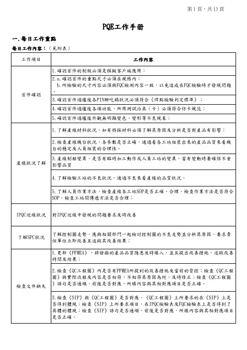
PQE工作手册一.每日工作重點每日工作內容:(見附表)二.試產與量產品質管控辦法1.試產品的品質管控验证合格后,供应商生产分模穴标识,Taisol0制程依会议决定,组装搭配,外箱标识;1.PIN不導通分析:e.客户(纬创)特殊要求,多模穴组合均需提供FAI ,每组合2PCS ,PQE 需先准备样品,FQC 执行;注:考虑BASE ,Plate 多模穴,搭配组合过多,验证时间过长,PQE 可召开会议,指定组合验证;d.pin 必须与BASE/PLATE 各穴组装确认其过炉前后多阶段插卡PIN 高的变化,耐久以及PIN 与卡的接触阻抗;3.多模具多模穴必须作以下验证:a.BASE 须验证过炉前后的变异(core9030),插拔力,耐久,若PLATE/COVER 也有多模穴,必须各种组合搭配验证;b.plate 分穴组装成品做耐久及过炉前后多阶段插卡PIN 高的变化,若PIN 与BASE 也有多模穴,必须各种组合搭配验证;c.cover 必须与BASE 各穴组装成成品确认其组合间隙,耐久及过炉吃锡状况;以上試產量產品的重點工站的管控要在QC-PLAN和IPQC巡檢文件中嚴格管控2.3.空焊分析4.PUSH 功能不良分析1、制程穩定性隱患的管控第 10 頁,共 12 頁管控表格見附件3對當日所發現的品質隱患填入品質隱患追蹤表內進行追蹤(如附件4)六.PQE文件制訂規范1.文件內容的制訂:PFMEA的制訂:1)制訂PFMEA前首先應熟悉,懂得其涵義及明白表單內容.(見附件PFMEA表單1).2) 懂得和熟悉PFMEA內容後根據產品的工程圖,試產量產問題點和相關客訴問題對應PFMEA表單來制訂具體內容3)根據隱患追蹤表裡面的內容隨時更新PFMEA,針對PFMEA每月與PEE/PE檢討一次改善。
4)PFMEA制訂時的注意事項:A.產品的失效模式和失效影響都必須真實,且對制程的管控和採取的措施都對其失效模式有針對性.B.當產品失效模式的風險指數超過100時,須有相關的改善措施並對措施進行跟進.C.失效模式改善前後其失效模式的嚴重度必須一致,不可有改善後失效模式嚴重度有變化的現象.D.PFMEA中必須有重點管控點的SPEC及說明QC PLAN的制訂:1)制訂QC PLAN前首先也必須熟悉明白其表單內容.(見附件2 QC PLAN表單).2)根據PFMEA中制程管制計劃和改善措施與產線各工站對應制訂產品的管控方法,並簡明描述管控重點.3)QC-PLAN要根據產線和客戶的狀況隨時更新管控辦法4)QC PLAN制訂時的注意事項:A.PFMEA中對制程的管控在QC PLAN中必須得到體現.B.QC PLAN管控方法須正確且前後一致.C.QC PLAN中必須有重點管控點的SPEC及說明制程SIP的制訂:1)熟悉,明白制程SIP表單及其內容.2)根據QC PLAN中管控方法和管控點,參照《制程檢驗規范》詳細描述產品各加工工站對人機物料的管控與檢驗.3) 制程SIP的制訂時的注意事項:A.制程SIP制訂時須根據公司實際情況與客戶要求相結合.B.制程SIP中的各作業流程工站須與QC PLAN中的流程工站相對應.C.制程SIP須對QC PLAN中的管制點進行詳細的描述,且重點管制點有明確SPEC及說明.第 11 頁,共 12 頁六.報告、報表的管理與歸檔1.報告、報表管理與歸檔的順序和原則:成品SIP的制訂:.1)熟悉,明白成品SIP表單及其內容.2)按QC PLAN中管控方法和管控點及《成品檢驗規范》制訂詳細具體的檢測方法與成品檢驗標準.3)成品SIP的制訂時的注意事項:A. 制程SIP制訂時須根據公司實際情況與客戶要求相結合.B.成品檢驗中檢測標準須符合檢驗標準.4)要制定成品檢驗SOP,讓FQC的檢驗次序和方法一致,防止漏檢顯目。
BPE(Byte Pair Encoding)算法是一种用于处理NLP任务的算法,主要用于解决NMT任务中的OOV(out-of-vocabulary)问题。
以下是BPE算法的调用过程:
1. 准备数据:首先需要准备要进行分词的数据,通常是一段文本。
2. 构建词汇表:将文本中的单词统计出来,并按照单词出现的频率制作成词汇表。
3. 初始化解码器:初始化一个解码器,用于将分词结果解码成原始文本。
4. 训练模型:使用BPE算法对分词模型进行训练,通过不断地优化模型参数,提高分词的准确率。
5. 进行分词:将待分词的文本输入到训练好的分词模型中,得到分词结果。
6. 结果处理:对分词结果进行进一步的处理,例如去除停用词、词性标注等。
7. 评估效果:对分词结果进行评估,可以通过准确率、召回率等指标来衡量分词效果的好坏。
8. 优化模型:根据评估结果对分词模型进行优化,以提高分词的准确率。
以上是BPE算法的基本调用过程,具体实现可能会因不同的任务和数据集而有所不同。
需要注意的是,BPE算法需要对数据进行预处理和后处理,例如去除标点符号、大小写转换等,以确保分词
结果的准确性。
Contents1SCOPE (2)2INSTALLATION (2)3VALVE OPERATION (3)4DISASSEMBLY (4)5ASSEMBLY (4)6REPAIR KITS (5)7BILL OF MATERIALS (6)1SCOPE1.1CAUTION1.1.1For your safety, read this manual before installation or servicing.1.1.2Before installing or servicing, please ensure the line pressure has been relieved and any hazardous fluids havebeen drained or purged from the system.1.1.3Ensure that all Lockout and Tagout procedures for the system have been properly implemented.1.2USE1.2.1A-T Controls HP-Series Ball Valve are available in Hygienic Ferrule Ends (½” & ¾” Type A, 1”-4” Type B) orExtended Tube Butt Weld Ends.1.2.2Maximum results and optimum valve life can be maintained under normal service conditions and in accordancewith pressure/temperature ratings and corrosion data charts.2INSTALLATION2.2A-T Controls HP-Series Ball Valves are bi-directional and can be installed with the flow in either direction. Thevalve can be mounted in any position so that the handle, gear, or actuator has proper clearance, allows foroptimal drainage, can be easily accessed, and the open/close indicator can be viewed. If the gear is equipped witha chain wheel, the valve shall be mounted in a way so that the chain does not come in contact with the valve orpipeline.2.3Before installation of the valves, the pipe must be flushed clean of dirt, burrs, and welding residues. Failure to doso can cause the seats, sealing surfaces, and internal polish to be damaged.2.4The pipe must be free from tension and in proper alignment.2.5Before installation of the valves, check to ensure that all connections are free from defects.2.6Be sure to consult with supplier of your clamps and gaskets to be used on the hygienic ends for the propermaterial, pressure rating, and clamp torque for your process. Over torqueing clamps may result in damage to the ferrule end.2.7Disassembly of the valve is not necessary for tube end valves. However, caution should be taken to ensure thatthe heat source does not come in contact with the sealing components of the valve in excess of the sealingcomponent temperature limitation.3VALVE OPERATION3.1MANUAL3.1.1HandleTo open the valve, turn the handle counter-clockwise until the handle is parallel with the pipeline andthe handle has contacted the handle stop.To close the valve, turn the handle clockwise until the handle is perpendicular with the pipeline and thehandle has contact the handle stop.An optional locking device can be provided to lock out the valve in the open or closed position. Once thevalve is in the desired position, place an appropriate size lock or hasp through the holes in the lockingarm and locking plate. If it can be performed safely, try to turn to ensure that the valve has been lockedproperly.3.1.2GearTo OPEN the valve; turn the hand wheel counter-clockwise. The indicator will be pointing to the openposition and stop rotating when fully opened. The flow can be adjusted by stopping the indicatoranywhere between open and close.To CLOSE the valve; turn the hand wheel clockwise. The indicator will be pointing to the close positionand the hand wheel will stop rotating when fully closed. The flow can be adjusted by stopping theindicator anywhere between open and close.3.2AUTOMATEDA-T Controls HP-Series High Purity Ball Valves can be mounted with quarter turn actuators. Valves withactuators shall be checked for proper valve stem alignment. Angular or linear misalignments may resultin high operational torque and unnecessary wear on the valve stem. See the actuator IOM forinformation on operating the actuator.4DISASSEMBLYWARNINGCAUTION, FLUIDS CAN BE TRAPPED IN THE BODY OF THE VALVE, POSSIBILY UNDER HIGH PRESSURE. FOR YOUR SAFETY, IT IS IMPORTANT THAT PRECAUTIONS ARE TAKEN BEFORE REMOVAL OF THE VALVE FROM THE LINE OR ANY DISASSEMBLY.4.1Remove actuator or gear if equipped.4.2Care should be taken to not damage the surface finish of the valve components.4.3Remove the ends (2/3) from the body by removing the body bolts (7) and body nuts (8).4.4Remove the seat/body gasket (5) from both sides of the body (1). Once removed, with the valve in the fully closedposition, the ball (4) should slide freely out of the body (1).4.5If equipped, remove the handle nut (13), handle (15), handle stop (16), and locking device (17/18). Once removed,the locking saddle (14) should be free to remove.4.6While holding the stem (6) stationary, remove the packing nut (13). Once removed, the conical spring washers(12) and packing gland (11) should be free to remove.4.7While holding the bottom of the stem (6), push the stem (6) through the inside of the valve body (1).4.8Remove the packing set (10) and thrust bearing (9).4.9Inspect all components for damage and if necessary clean or replace.5ASSEMBLY5.1Care should be taken to not damage the surface finish of the valve components.5.2Place thrust bearing (9) on the stem (6) and install it by going through the body (1). Insert V-Style packing set (10)over stem (6) with the V pointing away from the valve (see Bill of Materials for correct orientation).5.3Install the packing gland (11), the conical spring washers (12), and packing nut (13). While holding the stem (6),tighten the packing nut (13) to the torque listed in the Fastener Torque Chart. Place the locking saddle (14) over the nut (13). Tighten further if needed in order to be able to place the locking saddle (14) over the packing nut(13).5.4Ensure that the stem (6) is in the closed position with the bottom tang parallel with the flow of the valve. Insert aseat/body gasket (5) in one side of the body (1). Carefully slide the ball (4) into body (1) and insert the otherseat/body gasket (5).5.5Assemble ends (2/3) onto body (1). Insert all body bolts (7) and nuts (8) into valve and tighten to finger tight,making sure that the ends (2/3) are flat against the body (1). Tighten all bolts (7) (on both sides for valves 2-1/2”- 4”) from the nut (8) side (if equipped) in a star pattern to 50% of the final torque shown in the Fastener Torque Chart. Using the handle (15) or an adjustable wrench, cycle the valve 3 times. Tighten all of the body bolts (7) to the final torque in a star pattern. Cycle the valve 3 times again. Check each body bolt torque (7) and tighten if needed a final time. It is acceptable for the torque to relax slightly over time due to relaxation of the polymer components, but the valve will still seal properly. If leakage is detected, repeat the steps for tightening the body bolts.5.6If required, assemble the locking device (14), handle stop (16), handle (15), and handle nut (13).Fastener Torque ChartValve SizeBody Bolt Torque (in *lbs) Packing NutTorque (in*lbs) 50% of Final Torque Final Torque1/2" 125 250 503/4" 125 250 501" 138 275 1001-1/2" 150 300 1002" 275 550 2002-1/2" 138 275 2003" 138 275 3504" 138 275 3506REPAIR KITSRepair kits are available to replace all soft goods. See Bill of Materials for components that are included in the repair kits.7BILL OF MATERIALSITEM NO. PART NAME REPAIR KIT QTY MATERIAL1 BODY 1 ASTM A182-F316L2 END CONNECTION 2 ASTM A182-F316L3 END CONNECTION 2 ASTM A182-F316L4 BALL 1 ASTM A479-316L5 SEAT/BODY GASKET X 2 TFM-1600 FDA6 STEM 1 ASTM A182-F316L7 BODY BOLT # ASTM A193 GR B88 BODY NUT & ASTM A194 GR 89 THRUST BEARING X 1 TFM-1600 FDA10 PACKING SET X 1 TFM-1600 FDA11 PACKING GLAND 1 ASTM A276-31612 CONICAL SPRING WASHER 2 ASTM A167-30213 PACKING/HANDLE NUT 2 ASTM A276-31614 LOCKING SADDLE 1 ASTM A167-30215 HANDLE 1 ASTM A240-30416 HANDLE STOP 1 ASTM A276-31617 LOCKING ARM 1 AISI 304SS18 LOCKING PLATE 1 AISI 304SS# FOR 1/2"-2" - 4 PCS; FOR 2-1/2" - 20 PCS; FOR 3" - 16 PCS, FOR 4" -24 PCS& FOR 1/2"-2" - 4 PCS; FOR 2-1/2"-4" - 0 PCSA-T Controls product, when properly selected, is designed to perform its intended function safely during its useful life. However, the purchaser or user of A-T Controls products should be aware that A-T Controls products might be used in numerous applications under a wide variety of industrial service conditions. Although A-T Controls can provide general guidelines, it cannot provide specific data and warnings for all possible applications. The purchaser / user must therefore assume the ultimate responsibility for the proper sizing and selection, installation, operation, and maintenance of A-T Controls products. The user should read and understand the installation operation maintenance (IOM) instructions included with the product and train its employees and contractors in the safe use of A-T Controls products in connection with the specific application.While the information and specifications contained in this literature are believed to be accurate, they are supplied for informative purposes only. Because A-T Controls is continually improving and upgrading its product design, the specifications, dimensions and information contained in this literature are subject to change without notice. Should any question arise concerning these specifications, the purchaser/user should contact A-T Controls.For product specifications go to https:///Downloads/A-T Controls, Inc. • 9955 International Boulevard, Cincinnati, OH 45246 • Phone: (513) 530-5175 • Fax: (513) 247-5462 • 。


bpe编码词汇表-概述说明以及解释1.引言1.1 概述概述:BPE(Byte Pair Encoding)是一种流行的无损数据压缩技术,常用于自然语言处理领域中的词分割和子词分割任务。
本文将深入探讨BPE编码的原理、优势以及应用,希望能够为读者提供关于BPE编码的全面理解和实际应用指导。
我们将首先介绍BPE编码的基本概念,接着讨论BPE编码相对于其他编码方式的优势,最后探讨BPE编码在自然语言处理中的具体应用场景。
通过本文的阐述,读者将能够更深入地理解BPE编码的重要性,以及对未来BPE编码技术发展进行展望。
我们相信,BPE编码将在自然语言处理领域持续发挥重要作用,推动技术的不断进步。
1.2 文章结构文章结构部分的内容如下:在本文中,我们将首先介绍BPE编码是什么,其优势和应用。
随后,我们将总结BPE编码在自然语言处理领域的重要性,并展望未来的发展方向。
最后,我们将得出结论,强调BPE编码的重要性和潜力。
通过这样的结构,我们希望读者能够全面了解BPE编码,并对其在实际应用中的价值有更深入的认识。
1.3 目的本文的目的是介绍BPE编码词汇表的概念、优势以及应用。
通过深入探讨这些内容,我们希望读者能够全面了解BPE编码在自然语言处理中的重要性和实用性。
我们将详细解释BPE编码是如何帮助提高文本处理和机器翻译等任务的效率,以及它在语言模型训练和词向量表示方面的作用。
最终,我们希望读者能够认识到BPE编码在当前自然语言处理领域所扮演的关键角色,以及对未来发展的启示和指导。
2.正文2.1 什么是BPE编码:BPE编码(Byte Pair Encoding)是一种基于数据压缩算法的词汇处理技术,最初由斯坦福大学的几位研究人员提出并应用于自然语言处理领域。
BPE编码的基本思想是将原始的词汇表根据频率和规则进行合并,从而生成一个更加紧凑且高效的词汇表。
具体来说,BPE编码首先将所有的词汇按照字符划分成最小的单元,比如字母或者汉字。
ASME BPE 生物加工设备GR部分一般要求GR—1 简介此标准所规定的要求,在生物处理﹑制药和私人保健品行业设备的设计非常实用.所涉及的方面包括灭菌﹑清洁﹑材质﹑尺寸﹑公差﹑表面抛光﹑原料连接和密封等。
这些应用于:(a)在制造﹑改进和提高过程中与产品﹑原料﹑产品介质直接接触的元件;(b)产品制造中主要部件系统(如WFI,清洁蒸汽,过滤和半成品贮存等)此标准不能应用于以下部分:不与成品或制造阶段介质部分直接接触的系统(如计算机系统,电气导管以及外部系统支撑结构)。
蒸汽消毒系统通常要满足压力容器设计编码.其他的设备或系统在经过厂家和用户同意下,不需要遵循这些编码。
在压力条件下操作时,系统的设计结构应分别符合ASME锅炉和压力容器编码,第VIII章节,第1部分和ASME B31.3管道处理编码,用户能对说明和要求另行规定。
当法律或强制机构(如市级,省级,州级或联邦)对此应用程序有明文规定时,最终的设计要求应符合这些法律规定。
然而,一些标准虽然不符合现在BPE标准,以前所提到的构造编码也是满足的(如焊接接受标准,检察要求,压力测试等).GR-2 范围生物处理﹑制药﹑私人保健品行业的要求标准和其它相关的卫生高等级要求一样,覆盖物直接或间接的影响原料﹑设计﹑构造﹑压力系统(容器和管路)﹑检查﹑审核﹑测试和证明。
此标准中没有明确规定的条款和要求并不意味着禁用,工程判断一定要符合此标准的基本原理准则,不能忽略强制规定规则或此标准明确的禁用条款。
GR-3 检查此标准的每一部分都有详细的检查要求。
如果需要一个检查程序,在经过用户﹑订约人﹑检查订约人和工程师同意后要保证系统和部件满足此标准.GR—5 责任检查人员的职责包括以下部分:GR-5。
1 压力容器用户检查员职责按照ASME BPVC, VIII 章节,第1部分,UG-91规定。
GR-5.2 管路,管道系统和无编码容器用户检查员职责按照ASME B31.3 340。

AMSE BPE Bioprocessing Equipment生物加工设备生物加工设备GR部分一般要求GR-1简介INTRODUCTION此标准所规定的要求,在生物处理﹑制药和个人保健品行业设备的设计非常实用,所涉及方面包括灭菌﹑清洁﹑材质﹑尺寸﹑公差﹑表面抛光﹑材料接合和密封等。
主要应用于:This Standard provides the requirements applicable to the design of equipment used in the bioprocessing,pharmaceutical,and personal care product industries,including aspects related to sterility and cleanability,materials,dimensions and tolerances, surface finish,material joining,and seals.These apply to:(a)在制造﹑改进和提高过程中与产品﹑原料﹑产品介质直接接触的关键部件;(b)产品制造中主要部件系统(如WFI,清洁蒸汽,过滤和半成品贮存等)(a)components that are in contact with the product,raw materials,or productintermediates during manufacturing,development,or scale-up;(b)systems that are a critical part of product manufacture[e.g.,water-for-injection(WFI),clean steam,filtration,and intermediate product storage].此标准不能应用于以下部分:不与成品或制造阶段介质部分直接接触的系统(如计算机系统,电气导管以及外部系统支撑结构)。
behr S 5 fully automatic steam distillation apparatusOperating ManualPlease read this operating manual carefully before starting use of your new behr S 5 steam distillation apparatus! The operating manual provides clear and simple instructions in the use of the apparatus. Additional information, which is useful and important for an understanding of the operating principles of the apparatus, is denoted by a gray stripe in the margin.We wish you success in the use of thebehrS 5 Steam Distillation ApparatusSafety WarningsIn order to avoid electrical shock injury, please insure that no liquids get into the apparatus housingor come in contact with the electrical wires and connections!To avoid electrical shock injury, always remove the electrical power (mains plug before opening the apparatus housing!Repair of electrical, electronic and mechanical components is only to be performed by suitably quali-fied and authorized personnel!Please rigorously observe all pertinent safety measures to avoid injury in working with glass!Observe carefully safety procedures in working with acids and bases, which can cause burns and other injuries!During the distillation and for a short time thereafter, do not touch any parts of the distillation system behind the Plexiglas door! These components may be hot and can cause burn injury!Do not operate the S 5 steam distillation apparatus in damp or explosive atmospheres!The maximum allowable humidity is 80%The maximum allowable room temperature iS 50 °CBefore shutting the S 5 down22 Inserting the vessels22 Switching the steam distillation apparatuson22Rinsing 22 Purging program23Adapting the behr S 5 to your personal requirements24 Choosing the language24 Configur ng the level sensor24 Setting the time24 Download Software-Updates24 selecting titration unit24 Cooling Water Source Setting24 What to do if (25Problems which you can solve yourself25 Sample vessel not inserted25 Insuffi cient cooling water pressure25 Reagent level sensors25 In the event that you are not using thebehr KAS 50 canister set:25In the event that you are using the behrKAS 50 canister set:25 Titration vessel is full26 Problems requiring the attention of the behr repair service27 Technical Specifications28Overwiew: Menus and displays of the behr S 529Table of ContentsContents of Delivery5 Use of the behr S 5 in Chemical Analyses5 Operating Conditions5 Installing the behr S 57 Emplacing the steam distillation apparatus7 Connecting the hoses and tubing8 Connecting to the electrical power line8 Front view of the behr S 511 Turning the steam distillation apparatus on12 Preparations12 Switching the S 5 on12 Distilling with the behr S 513 The operating control unit13 Programming the S 513 Distilling16 (Refi lling the reagent lin es16Inserting the glass components16Switching the steam distillationapparatus on16 Performing the (refill ng17 Test run17Inserting the glass vessels17Switching the steam distillationapparatus on17 Starting the test run18Ending the test run18 Automatic Distillation with the behr S 519Inserting the vessels19Switching the steam distillationapparatus on19 Starting the automatic distillation19Interrupting or terminating thedistillationprogram19 Ending the automatic distillation19 Manual distillation with the behr S 520Inserting the sample vessel20Switching the steam distillationapparatus on20 Performing a manual distillation20Ending the manual distillation21Contents of DeliveryPlease check immediately upon receipt to see that the contents of delivery are complete and undamaged.In the event of damage in shipment, contact the ship-ping agent (mail, freight carrier, railway immediately and request an inspection of actual condition of contents and packaging.The components, which should be present, are itemized in the following list.List of Componentsbehr S 5 distillation apparatus, completely assembled Hose set:1 Water inlet hose, 10/17, with ½“ and ¾“ standard fi t-tings, 2 m1 Verprene tubing, 8/12,2 m3 PVC tubing, 4/7, 2 m2 PVC tubing, 8/12, 2 m3 PVC tube, 6 x 1, 420 mm1 PVC tube, 10 x 1, 420 mm1 Electrical (mains cable1 Cable for titrator connection1 Cable for pHelectrode1 Crucible tongs Use of the behr S 5in Chemical AnalysesThe behr S 5 is an effective automatic distillation appa-ratus for use in various applications. Principally, it fi nds application in the steam distillation of Kjeldahl ammonia solutions. In this application, the automatic addition of NaOH, H2O and H3BO3, as well as the automatic drain-ing of spent sample waste, provide for a high degree of safety and convenience in use.Be certain to carefully implement the following guidance for the sake of safety in operation and the greatest pos-sible working life of the behr S 5:— Operate the apparatus always in accordance with the instructions and warnings in this operatingmanual!Modifi cation or changes to the apparatus areunauthorized and lead to termination of the guar-antee. Modifi cations may result in serious opera-tional safety hazards and /or reduced reliability of the S 5.— Do not expose the steam distillation unit to cor-rosive vapors, such as acids, bases or organicsolvents!Operating ConditionsOperate the behr S 5 steam distillation apparatus un-der normal laboratory conditions.The S 5 steam distillation apparatus may be con-nected to a cold water tap having a standard ½“ pipe thread.Contents of Delivery– 5 –© behr Labor-Technik 20061.11.21.31.41.51.61.71.81.91.111.141.151.161.101.131.12Figure. 1: behr S 5 – rear viewRear view of the behr S 5Figure 1: Diagram Legend1.1Overpressure steam release 1.9Diaphragm pump for delivery of boric acid;Connection nipple for 4/7 PVC tubing1.2.Cooling water inlet connection with filtersieve; ¾“ connection for 10/17 PVC hose1.10Socket for electrical (Mains power cable 1.3Water outlet, 8/12 PVC tubing 1.11Socket for level monitoring1.4Peristaltic pump for sample waste disposal;-Connection nipple for 8/12 Verprene tubing1.12Printer port1.5Diaphragm pump for H2O for steam genera-tion; Connection nipple for 4/7 PVC-tubing1.13RS 232 port for titrator1.6Diaphragm pump for NaOH; Connection nip-ple for 8/12 PVC-tubing1.1425-pin port for titrator1.7Excessive temperature circuit breaker 1.15RS 232 port for software updates1.8Diaphragm pump for delivery of sample dilutionwater; Connection nipple for 4/7 PVC tubing1.16Socket for air ventInstalling the behr S 5— In installing the S 5, be certain to adhere to all building codes pertaining to plumbing and towaste water disposal regulations.— In selecting the location for installation, keep in mind that the hoses and tubing provided have a length of 2 meters.Place the behr S 5 steam distillation apparatus on a sturdy horizontal fl at laboratory bench top, with access to both water tap and drain and suffi cient space for the reagent containers below the bench top.Select a cold water tap to which you can permanently attach the hose for the cooling water supply.— Faucets providing a mixture of hot and/or cold water should not be used.— The water pressure must be at least 0.5 bar for the proper functioning of the water pressuresafety monitor.The steam distillation unit is completely assembled by the manufacturer. Please unpack it carefully.Emplacing the steam distillation apparatusPlace the apparatus on the bench top.Unpack the accessory parts.First, put the reagent containers in place:Container for distilled waterContainer for sodium hydroxide (NaOHContainer for boric acid (H3BO3Container for sample wasteThe optimal location for these containers is directly be-neath the laboratory bench top.— In no case should the reagent containers be placed at a level higher than the steam distillation apparatus.Connecting the hoses and tubing— Pay careful attention to the labels of the hose and tube connections found on the back of the S 5.Insert the ends of the three 6 x 1 PVC tubes into the three 4/7 PVC tubing segments.Next insert the end of the 10 x 1 PVC tube into an 8/12 PVC tubing segment.— Make certain that the tubes are securely inserted in the PVC tubing segments.Insert two 6x1 PVC tubes into the container for distilled water. Connect the free ends of the PVC tubing seg-ments to the following connection nipples on the rear of the S 5:H2O for steam generator (1.5,H2O sample (1.8.Insert the third 6x1 PVC tube into the container for the boric acid and connect the free end of the PVC tubingsegment to the connection nipple labelled H3BO3(1.9on the back of the S 5.After inserting the 10x1 PVC tube into the container for NaOH, connect the free end of the PVC tubing segment to the connection nipple labelled NaOH (1.6 on the rear of the S 5.Using the pressure-resistant fabric-reinforced hose, con-nect the cold water tap½“ pipe thread to the ¾“ fi tting labelled cooling water inlet with fi lter (1.2 on the rear of the S 5.Finally, connect the two discharge tubing segments:Connect the Verprene 8/12 sample waste discharge tubing segment to the connection nipple labelled pump for suction sample (1.4 and insert into the container for sample waste discharge.Connect the 8/12 PVC tube segment to the connection nipple labelled water outlet (1.3 and lead the other end to a drain.File the tubing of the titration device and the electrode cable through the opening (2.9, cf. page 10.Screw the tubing to the titration device. Connect the other side to the tirator (see user’s manual of the tirator.Electrical connectionsConnect the titrator connection cable to the appropriate port of the S 5: Depending on the type of your titrator, it will fi t into the RS 232 socket (1.13 or the 25-pin socket (1.14.Screw the pHelectrode to the electrode cable.Connect the other sides of the electrode cable and of the connection cable to the titrator.Fill some KCl solution (KCl 3 mol/l into the electrode protection vessel (2.8, page 10.Gently pull the protection cap off the electrode and put the electrode into the electrode protection vessel (2.8.When you are not doing analyses, always keepthe electrode in the protection vessel (2.8. Makesure there is enough KCl solution in the vessel soas to keep the electrode membrane wet. Do notleave the electrode dry; it would dry out andbecome useless.In case you are using the container set KAS 50:• Connect the individual sensor cables from the vari-ous reagent containers to the central junction box.Then connect the cable from the central junction box to the socket labelled LEVEL DETECTORS (1.11 on the rear of the S 5.Connecting to the electrical power lineFirst, insure that the voltage specifi cation stated on the model identifi cation sticker of your S 5 corresponds to the electrical line voltage.Insure that the electrical power MAIN SWITCH (2.11 on the front of the S 5 is set to “0“.Connect the electrical power cable to the socket on the rear of the S 5 identifi ed as MAINS (1.10..Insert the plug of the power cable into an electrical power socket.Calibrating the pHelectrodeSee user’s manual of your titrator.2.12.42.22.32.52.62.102.112.132.142.152.30 2.312.322.122.72.82.9Figure 2: behr S 5 – Front viewFront view of the behr S 5 Figure 2: Diagram legend2.1Operating control unit: Chemical-resistantplastic foil 2.17Distillate level sensors (the 2nd is hiddenbehind the stirrer2.2.Liquid crystal display (LCD 2.18Protection vessel for pH electrode 2.3Control knob 2.19Drip tray2.4Cooling water outlet 2.20PTFE steam delivery tube2.5Screw-on connectors GL 14 2.21Notch for positioning the steam delivery tubebetween distillations2.6Cooling water inlet 2.22Quick release fastener for holding the samplevessels during distillation2.7Distillate suction tube, silicone 2.23Plexiglass protective door (not shown2.8Silicone delivery tube for H3BO32.24Fastening screws for glassware mounting2.9Opening for electrode cable and titration tube 2.25Glassware mounting2.10Distillate delivery tube, silicone 8/12 2.26Viton stopper for sealing vessel mouth2.11Air release valve 2.27GL 18 screw-on connectors with silicone gaskets2.12Titration device 2.28PTFE delivery tube for NaOH2.13Stirrer 2.29Distillation head, glass2.14Titration vessel 2.30Polypropylene steam/water inlet junction withpolypropylene nut2.15Electrical power switch 2.31GL 32 screw-on connector with silicone gasket 2.16Lid opening for pHelectrode 2.32Condenserbehr S 5Turning the steam distillation apparatus onPreparationsAcids and bases can cause burns and otherinjuries!Sample vessel will become hot; it can causeburns!In working with acids and bases, observe thesafety precautions prescribed for these sub-stances in the Material Safety Data Sheets!Before switching the steam distillation appara-tus on, close the plexiglass door!Fill the reagent containers with the appropriate chemi-cals.Verify by checking the tubing connections which rea-gents are to be fi lled into which containers. The n fi ll the containers accordingly:• Distilled or deionized water (e.g. from a behropur®water deionizer• NaOH, 32%• H3BO3, 2 - 4%Provide the cooling water supplyOpen the water tap.Switching the S 5 onTurn the power on by switching the MAIN SWITCH (2.11 on the front of the S 5 to the position …I“.The electrical power switch of the S 5 fulfi lls twofunctions. It serves to turn the apparatus on andoff and also has an electrical circuit-breaker builtin.This circuit breaker operates on a similar principalto those used in homes. If too much current isdrawn, it shuts off.The operation of this circuit breaker requires thata spring within it be cocked. For this reason, asomewhat greater pressure is required on theswitch to turn it on than is required in a similarswitch without circuit breaker.After turning the apparatus on, the display (2.3 on the front will briefl y show an initialization notifi cation. Im-mediately thereafter, the pump begins fi lling the steam generator and you see the following notifi cation on the display:steam generator fi llingAn hourglass symbolizes the ongoing process. Next, the following notifi cation appears:steam generator heatingAgain, the hour glass is seen on the display.These two procedures can take a bit of time, especially when the apparatus is switched on for the fi rst time. These procedures have been completed when thedisplay switches to the …Start“ modeThe S 5 steam distillation apparatus is now ready foroperation.Figure 3: Operating control unitDistilling with the behr S 5The operating control unitProgramming the S 5After fi ll ng and heating of the steam generator you willsee the following display:This is the main menu . From here you come to all other menus and displays. The option START is pre-programmed as a default set-ting.Distilling with the behr S 5Your behr S 5 steam distillation apparatus is program-med and operated easily with a single knob.The principle remains in all cases the same:Turning the knob enables you to choose an option. The currently addressable option is recognized by being highlighted with green text on a black background.The knob may be turned in both directions. In doing this, you will pass all possible options in the display shown and will always again fi nd the de sired option on continu-ed turning. Try this for yourself.The desired option is implemented by pressing on the knob.The complete procedure of choosing by turning and im-plementing by pressing will henceforth simply be called …selecting“.The following pages will show you how to program and operate you steam distillation apparatus.behr S 5Modifying a distillation programWith the S5, you can defi ne 99 different distillation programs. This allows you to defi ne the appropriate conditions and the appropr iate quantities of reagents for different analyses and different sample concentration ranges.The 100th programm, program no. 00, is a cleaning program which purges the distillation head with steam.When defi nng a program, make a note of its purpose and the settings you made.Turn the operating control knob clockwise orcounterclockwise until the menu item Program is highlighted. Then press the knob once.You will now see the following display:You can now select which of the 99 programs of the S 5 you wish to enter or modify. Simply turn the operating control knob until Prog.Number appears in green on a black background. If you now press the knob once, you will be able to dial to another number. Turning the knob clockwise advances the display to the higher numbers, while turning counterclockwise brings you to the lowernumbers. At both ends of the number range, continued turning of the knob will bring you to the other end of the range, specifi cally turning clockwise beyond 99 will bring you back to 00turning counterclockwise from 00 will bring you to 99.By pressing on the operating control knob you will then enter the programming options of the selected program number.If you are working with the S 5 for the fi rst time, then leave the program number selection on 01.By turning the operating control knob and pressing, select the option further==>.You will now see the following menu displayed:Read the menu items as follows:Prog.Number 01You can modify the settings of program no. 01DIL.H 2ODelivery time for dilution water in seconds. Possible entry values range from 0.0 sec to 99.9 sec. The factory default setting is 3.0 sec.Delivery of the pump approx.16 ml/sec.80 ml/5 sec 965 ml/minNaOHDelivery time for sodium hydro-xide in seconds. Possible entry values range from 0.0 sec to 99.9 sec. The factory default setting is 3.0 sec.Delivery of the pump approx.10 ml/sec.51 ml/5 sec 610 ml/minDist.TimeDistillation time in seconds. Possible entry values range from 0 sec to 999 sec. The factory default setting is 300 sec.<==back ==>furtherIf you wish to change an entry, simply turn the operating control knob to highlight the value of interest and press the knob to access the entry value. Then dial the desi-redvalue by turning the operating control knob and en-ter it in memory storage by pressing the knob again.Once all entry values have been entered according to your wishes, select further ==> and press the operatingcontrol knob to bring up the following program menu.Explanation:Prog.Number 01You can modify the settings ofprogram no. 01REAC.TIME Delay time in seconds betweenthe end of NaOH addition and thestart of distillation. Possible entryvalues range from 0 sec to 999sec. The factory default settingis 0 sec. For the distillation in theKjeldahl nitrogen determination,do not change the preset defaultof 000.POWER Steam generator power. Possibleentry values range from 30% to100%. The factory preset defaultvalue is 80%. You can change theelectrical power for steam gene-ration and thereby the intensity ofsteam generation.The steam generator is switchedon and off on by a pressure sen-sor. The on/off set points of thepressure sensor cannot be adjus-ted by the user. It is only possiblefor the user to adjust the steamgeneration power. DRAINSAMPLE Run-time in seconds for the pump draining the sample waste afterdistillation. Possible entry valuesrange from 0 sec to 999 sec. Thefactory default setting is 30 sec.<==back==>furtherIf you wish to change any of the values, select the desi-red parameter by turning the operating control knob. Press on the control knob to access the numerical entry value. Then dial the desired value by turning the ope-rating control knob and enter it in memory storage by pressing the knob again.Once all entry values have been entered according to your wishes, select further ==> and press the operatingcontrol knob to bring up the following program menu:Explanation:AutoEndPt Automatic endpoint determination.Before destillation, the S 5 deter-mines the pH of the boric acid;afterwards it titrates back to thispH. If AutoEndPt is Off, titrationgoes to a fi xed endpoint. Not alltitrators allow automatic endpointdetermination!DrainTitr Run-time in seconds for the pumpdraining the distillate after titration.Possible entry values range from0 sec to 999 sec. The factorydefault setting is 30 sec.H3BO3Delivery time for boric acid into thetitration vessel in seconds.Possible entry values range from0.0 sec to 99.9 sec. The factorydefault setting is 3.0 sec.Delivery of the pump approx.1.4 ml/sec.14 ml/5 sec84 ml/min<==back==>furtherIf you wish to change any of the values, select the desi-red parameter by turning the operating control knob. Press on the control knob to access the numerical entry value.Then dial the desired value by turning the ope-rating control knob and enter it in memory storage by pressing the knob again.Distilling with the behr S 5behr S 5Once all entry values have been entered according to your wishes, select further ==> and press the operatingcontrol knob to bring up the following program menu:Explanation:SetPoint Endpoint preset for the titrati-on. Titration will go to this pH ifAutoEndPt is off.Not all titrators allow endpointsetting from the S5. With sometitrators the endpoint must be seton the titrator itself.Meas.Time Time in seconds for the endpointdetermination if AutoEndPt is onand the titrator allows automaticendpoint determination. The facto-ry default setting is 10 sec.Stirring Stirring power in % of maximum.The factory default setting is 30%. <==back==>furtherIf you wish to change any of the values, select the desi-red parameter by turning the operating control knob. Press on the control knob to access the numerical entry value. Then dial the desired value by turning the ope-rating control knob and enter it in memory storage by pressing the knob again.You have now completed program no. 01.Select <== back. By repeatedly pressing <== back you will return to the main menu.DistillingIn order to avoid electrical shock injury, pleaseinsure that no liquids get into the apparatushousing or come in contact with the electricalwires and connections!Please rigorously observe all pertinent safe-ty measures to avoid injury in working withglass!Observe carefully safety procedures in wor-king with acids and bases, which can causeburns and other injuries!During the distillation and for a short time the-reafter, do not touch any parts of the distillati-on system behind the plexiglass door. Thesecomponents may be hot and can cause burninjury!Do not operate the S 5 steam distillation ap-paratus in damp or explosive atmospheres!The maximum allowable humidity is 80%.The maximum allowable room temperature iS50 °C.(Refi lling the reagent linesBefore you use your S 5 for the fi rst time or after longer periods of disuse, the delivery pumps and tubing should be filled with the respective reagent, replacing any air or distilled water in the lines. By this you make sure all rea-gents will be delivered in the correct amounts.— Inspect the reagent containers and the tubing connections.— Open the water tap.Inserting the sample vesselGuide the PTFE steam delivery tube (2.20 into the mouth of an empty sample vessel. Seat the mouth of the vessel properly against the Viton stopper above (2.26 and secure the vessel in place from below by seating it in the recess of the quick-release fastener (2.22. Check for fi rm and complete seal of the vessel mouth against the Viton stopper.Insert the distillate delivery tube into an empty Erlen-meyer fl ask placed on the shelf beneath the condenser. Switching the steam distillation apparatus onClose the protective door and turn the apparatus on using the MAIN SWITCH(2.15.In the main menu, select Options.Performing th e (refi llingThe following menu appears:Select MANUAL ENTRY. The display will then appearas follows:Select DIL.H2O and hold the operating control knob(2.3 depressed until water fl ows into the sample vessel.Select NaOH and hold the operating control knob de-pressed until sodium hydroxide fl ows into the sample vessel.Now select further ==> to proceed to the next menu.Select H3BO3and hold the operating control knob (2.3depressed until boric acid fl ows into the titration vessel.Select DrainSample and hold the operating control knob (2.3 depressed until the liquid in the sample ves-sel has been drained.Select DrainTitr and hold the operating control knob (2.3 depressed until the liquid in the titratiopn vessel has been drained.Press the quick-release fastener (2.22 down and remove the sample vessel.Push the PTFE steam delivery tube (2.20 into its retai-ning notch (2.21.By repeatedly pressing <== back you will return to the main menu.Test runEspecially reliable and reproducible results will be obtai-ned if you performa …warm-up“ distillation without samp-le before starting your daily analyses.—In the course of this fi rst …warm-up“ distillation, the steam will come in contact with cold glasscomponents, leading to a higher degree of con-densate formation. This could lead to excessive dilution of an actual sample and to an excessive volume of liquid in the sample vessel.The introduction of steam at a temperture of ap-prox. 106°C results in noises, which can be loud.These noises are no cause for concern. With uti-lization of our high-quality behrotest® sample di-gestion vessels, models SR 3i, KJ 500 or KJ 750,the risk of glass breakage is minimal.Open the water tap.Inserting the glass vesselObserve carefully all pertinent safety measu-res to avoid injury in working with glass!Observe carefully safety procedures in wor-king with acids and bases, which can causeburns and other injuries!Insert the steam delivery tube (2.20 into an empty sample vessel. Press the quick release fastener (2.22 down and insert the sample vessel.Check to insure that the sample vessel is fi rmly seated against the Viton stopper (2.26.Switching the steam distillation apparatus on Close the protective door (2.23 and turn the apparatus on using the MAIN SWITCH (2.15.Following the initialization, the main menu appears:The menu selection Startis highlighted.Distilling with the behr S 5behr S 5Starting the test runDuring the distillation and for a short time the-reafter, do not touch any parts of the distillati-on system behind the plexiglass door. Thesecomponents may be hot and can cause burninjury!Select Options in the main menu.The following menu appears:Select MANUAL ENTRY. The display will then appearas follows:Select Steam. In this function the operating control knob (2.3 acts as an on/off switch.The introduction of steam is started by a short。
<WiseKernel Info Inc.><BPEL 简明开发手册>版本 <0.1>目录1.前言 (3)1.1关于BPEL简明开发手册 (3)1.2名词解释 (3)2.BPEL背景知识 (4)3.与WSDL的关系 (4)4.定义业务流程 (5)4.1BPEL实例教程 (5)5.业务流程的结构 (18)5.1<基元活动---B ASIC A CTIVITY> (21)5.1.1<Activity –invoke> (21)5.1.2<Activity –receive〉 (22)5.1.3<Activity –reply〉 (23)5.1.4<Activity –assign〉 (24)5.1.5<Activity –throw〉 (25)5.1.6<Activity –wait〉 (25)5.1.7<Activity –empty〉 (25)5.1.8<Activity –terminate〉 (26)5.1.9<Activity –compensate〉 (26)5.2<结构活动---S TRUCTURE A CTIVITY> (27)5.2.1<Activity –sequence〉 (27)5.2.2<Activity –switch〉 (27)5.2.3<Activity –while〉 (28)5.2.4<Activity –flow〉 (28)5.2.5<Activity –pick〉 (29)5.3<特殊活动---S COPE> (31)6.合作伙伴链接类型、合作伙伴、服务引用 (33)6.1合作伙伴链接 (33)6.2伙伴链接 (34)6.3服务引用 (34)7.参考手册 (36)1.1 1.2BPEL简明开发手册1.前言关于BPEL简明开发手册本手册是针对SIKA用户编写的BPEL简明开发手册,对其它开发人员学习BPEL也提供了一个相对容易的入门的学习手册。
目标分解在管理中,关键绩效指标将根据管理层级层层分解在东风小康,我们将指标体系分为一级、二级、三级。
其中:一级指标:是指公司确定下达到各单位(工厂)的指标二级指标:是指各单位(工厂)确定下达到各部门的指标三级指标:是指各部门内部分解指标目标分解(范例)不要陷入指标的泥潭小朋友打酱油妈妈叫儿子去买瓶酱油回来结果小朋友贪玩,半个小时才将酱油买回来妈妈很生气,于是要求儿子下次买酱油不能超过10分钟第二次,小朋友图省事,在楼下小卖部花了十块钱买酱油妈妈又很生气,说太贵了,于是要求儿子下次买酱油不能超过5元钱第三次,小朋友兴冲冲按照妈妈的要求买到了酱油,一不小心,摔了一跤,结果摔坏了手臂,酱油也撒了一地妈妈知道后又很生气,教训儿子下次买酱油一定要注意安全小朋友认识到,妈妈要他安全、快捷、便宜地买回酱油下次妈妈再叫他打酱油时,他开始注意妈妈的嘱咐,结果小朋友过于注重价格,买了一瓶劣质酱油回来妈妈一看,这种酱油炒菜味道不好,对儿子说,下次买酱油要挑牌子小朋友迷糊了,便宜没好货,牌子货又太贵,怎么办?小朋友于是决定,下次买的时候打电话问妈妈,这样就不会犯错误了。
――――? 关键绩效指标是对业务目标成败具有决定意义的衡量指标内容提纲背景介绍 BPE总论推进BPE 的流程、职责&方法BPE的关键绩效指标BPE 运行管理BPE项目的绩效管理:BPE评估考核BPE运行业务计划编制业务计划报告关键绩效指标公司一级指标工厂关键绩效指标现场绩效管理工具方法现场应用效果现场改善成果问题清单改进问题清单BPE评估是对业务管理的过程指导和改进,目的是识别差距,不断改进。
确保业务活动满足公司目标要求目视管理目视化管理的指导方针:不同层次目视不同信息。
只公布能给班组/工段/部门直接施加影响或让他们有特殊兴趣的信息。
保持并更新BPE板的信息对目视结果负责的经理应更新信息使用PDCA循环来目视信息更新要求及方法定期检查BPE目视墙(各级BPE的更新频次如下) 各单位(工厂)BPE:每月一次部门BPE:每周一次在计划上对延期、附加或改变均加以注释。
bpe流程BPE流程简介及应用领域BPE(Byte Pair Encoding)是一种基于统计的无监督分词算法,用于将文本进行分词处理。
在自然语言处理领域,分词是一项重要的预处理任务,对于机器翻译、文本分类、命名实体识别等任务具有重要意义。
本文将介绍BPE的流程以及其在各个领域的应用。
一、BPE流程1. 初始化:将原始语料库进行字符切分,得到所有字符的集合作为初始词表。
2. 构建词频统计表:遍历语料库中的所有句子,统计词频,得到每个字符或字符序列的出现次数。
3. 合并词频最高的字符对:从词频统计表中选取出现次数最多的字符对,将其合并为一个新的字符。
4. 更新词频统计表:更新词频统计表中合并后字符对的出现次数。
5. 重复步骤3和4,直到达到指定的词表大小或者满足其他停止条件。
6. 分词:按照合并后的字符构建词表,将句子进行分词处理。
二、BPE的应用领域1. 机器翻译:BPE可以将源语言和目标语言的句子进行分词处理,提高机器翻译的准确性和翻译质量。
2. 文本分类:BPE可以将文本进行分词处理,并将分词结果作为文本特征进行分类任务,提高分类的准确性和泛化能力。
3. 命名实体识别:BPE可以将文本进行分词处理,将命名实体从文本中提取出来,为命名实体识别任务提供更准确的输入。
4. 文本生成:BPE可以将文本进行分词处理,生成更加准确和流畅的文本,提高文本生成任务的效果。
5. 信息检索:BPE可以将查询文本进行分词处理,将查询词进行扩展,提高信息检索的准确性和召回率。
6. 语音识别:BPE可以将语音转换为文本时,对文本进行分词处理,提高语音识别的准确性和鲁棒性。
7. 语言模型:BPE可以将文本进行分词处理,用于语言模型的训练,提高语言模型的预测准确性和泛化能力。
8. 情感分析:BPE可以将文本进行分词处理,提取情感词汇,用于情感分析任务,提高情感分析的准确性和情感分类效果。
总结:BPE作为一种基于统计的无监督分词算法,在自然语言处理领域具有广泛的应用。